EP1698380B9 - Determination of spin parameters of a sports ball - Google Patents
Determination of spin parameters of a sports ball Download PDFInfo
- Publication number
- EP1698380B9 EP1698380B9 EP06004069A EP06004069A EP1698380B9 EP 1698380 B9 EP1698380 B9 EP 1698380B9 EP 06004069 A EP06004069 A EP 06004069A EP 06004069 A EP06004069 A EP 06004069A EP 1698380 B9 EP1698380 B9 EP 1698380B9
- Authority
- EP
- European Patent Office
- Prior art keywords
- frequency
- spin
- estimating
- ball
- sports ball
- Prior art date
- Legal status (The legal status is an assumption and is not a legal conclusion. Google has not performed a legal analysis and makes no representation as to the accuracy of the status listed.)
- Active
Links
- 238000001228 spectrum Methods 0.000 claims abstract description 41
- 238000000034 method Methods 0.000 claims abstract description 14
- 230000001133 acceleration Effects 0.000 claims description 21
- 230000005484 gravity Effects 0.000 claims description 4
- 230000005855 radiation Effects 0.000 description 4
- 238000009987 spinning Methods 0.000 description 4
- 238000005259 measurement Methods 0.000 description 3
- 238000001514 detection method Methods 0.000 description 2
- 239000011159 matrix material Substances 0.000 description 2
- 230000000737 periodic effect Effects 0.000 description 2
- 241000288673 Chiroptera Species 0.000 description 1
- 230000008901 benefit Effects 0.000 description 1
- 230000008859 change Effects 0.000 description 1
- 239000004020 conductor Substances 0.000 description 1
- 230000004069 differentiation Effects 0.000 description 1
- 230000000694 effects Effects 0.000 description 1
- 238000005516 engineering process Methods 0.000 description 1
- 235000000396 iron Nutrition 0.000 description 1
- 239000000463 material Substances 0.000 description 1
- 238000012067 mathematical method Methods 0.000 description 1
- 238000012986 modification Methods 0.000 description 1
- 230000004048 modification Effects 0.000 description 1
- 238000012144 step-by-step procedure Methods 0.000 description 1
- 238000012360 testing method Methods 0.000 description 1
- 230000036962 time dependent Effects 0.000 description 1
- 230000009466 transformation Effects 0.000 description 1
- 238000002604 ultrasonography Methods 0.000 description 1
Images


Classifications
-
- A—HUMAN NECESSITIES
- A63—SPORTS; GAMES; AMUSEMENTS
- A63B—APPARATUS FOR PHYSICAL TRAINING, GYMNASTICS, SWIMMING, CLIMBING, OR FENCING; BALL GAMES; TRAINING EQUIPMENT
- A63B24/00—Electric or electronic controls for exercising apparatus of preceding groups; Controlling or monitoring of exercises, sportive games, training or athletic performances
- A63B24/0021—Tracking a path or terminating locations
-
- A—HUMAN NECESSITIES
- A63—SPORTS; GAMES; AMUSEMENTS
- A63B—APPARATUS FOR PHYSICAL TRAINING, GYMNASTICS, SWIMMING, CLIMBING, OR FENCING; BALL GAMES; TRAINING EQUIPMENT
- A63B69/00—Training appliances or apparatus for special sports
- A63B69/36—Training appliances or apparatus for special sports for golf
- A63B69/3658—Means associated with the ball for indicating or measuring, e.g. speed, direction
-
- A—HUMAN NECESSITIES
- A63—SPORTS; GAMES; AMUSEMENTS
- A63B—APPARATUS FOR PHYSICAL TRAINING, GYMNASTICS, SWIMMING, CLIMBING, OR FENCING; BALL GAMES; TRAINING EQUIPMENT
- A63B24/00—Electric or electronic controls for exercising apparatus of preceding groups; Controlling or monitoring of exercises, sportive games, training or athletic performances
- A63B24/0021—Tracking a path or terminating locations
- A63B2024/0028—Tracking the path of an object, e.g. a ball inside a soccer pitch
- A63B2024/0034—Tracking the path of an object, e.g. a ball inside a soccer pitch during flight
-
- A—HUMAN NECESSITIES
- A63—SPORTS; GAMES; AMUSEMENTS
- A63B—APPARATUS FOR PHYSICAL TRAINING, GYMNASTICS, SWIMMING, CLIMBING, OR FENCING; BALL GAMES; TRAINING EQUIPMENT
- A63B2220/00—Measuring of physical parameters relating to sporting activity
- A63B2220/30—Speed
- A63B2220/34—Angular speed
- A63B2220/35—Spin
Definitions
- the present invention relates to the determination of spin parameters of a sports ball while in flight, and in particular to the determination of the spin axis and/or a rotational velocity of the sports ball.
- Such parameters are highly interesting both for using and developing sports balls and other sports equipment, such as golf clubs, irons, rackets, bats or the like used for launching sports balls.
- the present invention aims at being able to perform these determinations without altering the sports balls.
- a first aspect of the invention relates to a method of estimating a rotational velocity or spin frequency of a rotating sports ball in flight, the method comprising:
- any type of electromagnetic wave may be used, such as visible radiation, infrared radiation, ultrasound, radio waves, etc.
- any number of points in time may be used. It may be preferred to receive the radiation as long as a meaningful detection is possible or as long as the spectrum traces may be determined in the signal. Normally, the reception and subsequent signal analysis is performed at equidistant points in time.
- the frequency analysis may result in a spectrum of the signal. This, however, is not required in that only the equidistant spectrum traces are required.
- a spectrum trace is a sequence of frequencies which is at least substantially continuous in time but which may vary over time.
- a trace normally is a slowly decaying function, but any shape is in principle acceptable and determinable.
- step 1. comprises receiving the reflected electromagnetic waves using a receiver, and wherein step 2. comprises identifying, subsequent to the frequency analysis, a first frequency corresponding to a velocity of the ball in a direction toward or away from the receiver and wherein identification of the spectrum traces comprises identifying spectrum traces positioned symmetrically around the first frequency.
- step 2. comprises, for each point in time and sequentially in time:
- the predetermined amount or uncertainty within which a candidate should be may be a fixed amount, a fixed percentage or a measure depending on e.g. an overall signal-to-noise ratio determined.
- a second aspect of the invention relates to a system for estimating a rotational velocity or spin frequency of a rotating sports ball in flight, the system comprising:
- the means 2. may be adapted to identify, subsequent to the frequency analysis, a first frequency corresponding to a velocity of the ball in a direction toward or away from the receiver and to identify, as the spectrum traces, spectrum traces positioned symmetrically around the first frequency.
- a preferred manner of determining the velocity/frequency is one, wherein the means 2. are adapted to, for each point in time and sequentially in time:
- the orientation of the spin axis of a rotating ball has been measured by using cameras placed close to the launching area. These systems only provide the orientation of the spin axis in one point in space, right after launch.
- the present invention uses a 3 dimensional trajectory measuring equipment to measure the spin axis orientation during flight.
- the present invention makes it possible to have a continuous measurement of the spin frequency and spin axis orientation during the entire flight of the ball.
- the Doppler radar comprises a transmitter 4 and a receiver 5.
- the transmitting wave 6 at frequency Ftx is reflected on the ball 1, the reflected wave 7 from the ball 1 has a different frequency Frx.
- the difference between the reflected frequency and the transmitted frequency, is called the Doppler shift F dopp .
- F dopp is proportional to the relative speed Vrad of the reflecting point A on the ball 1 relative to the radar 3.
- F dopp , A 2 / ⁇ ⁇ V ⁇ rad , where ⁇ is the wavelength of the transmitting frequency.
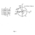
- a coordinate system 2 is defined as having origin in the center of the ball and X-axis always pointing directly away from the radar, the Z-axis is in the horizontal plane.
- the strongest reflection from the ball 1 will always be the point A which is perpendicular to the line-of-sight from the radar.
- the point A with the strongest reflection will in fact be different physical locations on the ball over time.
- the output signal from point B consist of the signal from point A modulated by a signal X modB (t):
- x mod ⁇ B t d t ⁇ exp j ⁇ 2 / ⁇ ⁇ r ⁇ ⁇ ⁇ sin ⁇ ⁇ t ⁇ t
- the exponential term of the modulating signal is recognized as a frequency modulation (FM) signal, with a modulation frequency of ⁇ /2 ⁇ and a frequency deviation of 2/ ⁇ *r* ⁇ .
- FM frequency modulation
- d(t) of the modulating signal in [6] will also have a time dependent variation.
- the relative strength of the individual harmonics of d(t) will depend on the reflection characteristics for the different aspect angles.
- the received signal will have equally spaced sidebands symmetrical around the Doppler shift F dopp,A , caused by the velocity of the ball.
- the sidebands will have multiple harmonics and will be spaced exactly the spin frequency of the ball ⁇ /2 ⁇ . Only in the case of a perfect spherical ball, there will be no modulation sidebands.
- FIG 2 the received signal spectrum of a golf ball in flight is shown.
- the spectrum contains a strong frequency line that corresponds to the velocity of the ball, as well as symmetric sidebands around this velocity that are equally spaced with the spin frequency.
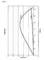
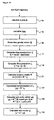
- the ball velocity is tracked 8 using standard tracking methods. Then symmetrical frequency peaks around the ball velocity is detected 9. In figure 3 the frequency offset of the symmetrical sidebands are shown relative to the ball velocity.
- the different harmonics of the spin sidebands are tracked over time using standard tracking methods 10.
- the different tracks are qualified 11, requiring the different harmonic tracks to be equally spaced in frequency.
- the different tracks are solved for their corresponding harmonic number 12. After this, the spin frequency can be determined from any of the qualified harmonic tracks 13, provided that the frequency is divided by the respective harmonic number.
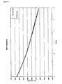
- the final spin frequency chart over time is shown in figure 5 , which contains all of the harmonic tracks.
- the step-by-step procedure for measuring the spin frequency is described in figure 7 .
- the 3 dimensional trajectory of the ball flight is obtained by appropriate instruments.
- the radar used for measuring the spin frequency is also used to provide a 3 dimensional trajectory of the ball flight, see figure 4 .
- balls that satisfy the rotational symmetry criteria are: golf balls, tennis balls, base balls, cricket balls, soccer balls etc.
- the drag is always 180 deg relative to the airspeed vector Vair.
- the lift acceleration L is caused by the spinning of the ball and is always in the direction given by ⁇ x Vair (x means vector cross product), i.e. 90 deg relative to the spin vector ⁇ and 90 deg relative to the airspeed vector Vair.
- the spin vector ⁇ describes the orientation of the spin axis, identified with the spin unity vector ⁇ e , and the magnitude of the spin vector ⁇ is the spin frequency ⁇ found through the algorithm described in figure 7 .
- trajectory velocity V and acceleration A are calculated by differentiation 14.
- the airspeed velocity is calculated 15 using equation [9], using a priori knowledge about the wind speed vector W.
- the gravity acceleration G is calculated 16 from a priori knowledge about latitude and attitude.
- D ⁇ A ⁇ ⁇ G ⁇ ⁇ V ⁇ air ⁇ / V ⁇ air ⁇ 2 ⁇ V ⁇ air ⁇ , where • means vector dot product.
- the spin unity vector ⁇ e is normally assumed to be constant over time for rotational symmetrical objects due to the gyroscopic effect. If the spin unity vector ⁇ e can be assumed to be constant over a time interval [t1;tn], then equation [12] constructs a set of linear equations [13].
- a rotation matrix R that converts the coordinates for the normal unity vector n in the base coordinate system to the x-axis unity vector [1,0,0], see equation [17].
Abstract
Description
- The present invention relates to the determination of spin parameters of a sports ball while in flight, and in particular to the determination of the spin axis and/or a rotational velocity of the sports ball.
- Such parameters are highly interesting both for using and developing sports balls and other sports equipment, such as golf clubs, irons, rackets, bats or the like used for launching sports balls.
- For golf balls, such determinations normally have been made by adding to the golf balls strips or patterns of a radar reflecting material. This, however, can only be made for test purposes in that this type of ball is highly standardized. Technologies of this type may be seen in
US-A-6,244,971 ,GB 2, 380 682US 6 292 130 ,US 5 401 026 ,US 5 700 204 ,US 5 138 322 , andUS 2002/0107078 . - The present invention aims at being able to perform these determinations without altering the sports balls.
- A first aspect of the invention relates to a method of estimating a rotational velocity or spin frequency of a rotating sports ball in flight, the method comprising:
- 1. a number of points in time during the flight, receiving electromagnetic waves reflected from the rotating sports ball and providing a corresponding signal,
- 2. performing a frequency analysis of the signal, and identifying two or more discrete spectrum traces positioned at least substantially equidistantly in frequency and being continuous over time, and
- 3. estimating the velocity/frequency from a frequency distance between the discrete spectrum lines.
- In the present context, any type of electromagnetic wave may be used, such as visible radiation, infrared radiation, ultrasound, radio waves, etc.
- In addition, any number of points in time may be used. It may be preferred to receive the radiation as long as a meaningful detection is possible or as long as the spectrum traces may be determined in the signal. Normally, the reception and subsequent signal analysis is performed at equidistant points in time.
- In order to ensure that the distance between the spectrum traces is correctly determined, preferably more than 2 equidistant spectrum traces are identified.
- Naturally, the frequency analysis may result in a spectrum of the signal. This, however, is not required in that only the equidistant spectrum traces are required.
- In this context, a spectrum trace is a sequence of frequencies which is at least substantially continuous in time but which may vary over time. In the present context, a trace normally is a slowly decaying function, but any shape is in principle acceptable and determinable.
- Preferably,
step 1. comprises receiving the reflected electromagnetic waves using a receiver, and whereinstep 2. comprises identifying, subsequent to the frequency analysis, a first frequency corresponding to a velocity of the ball in a direction toward or away from the receiver and wherein identification of the spectrum traces comprises identifying spectrum traces positioned symmetrically around the first frequency. - In this manner, another frequency is determined which may aid in ensuring that the equidistant spectrum lines are correctly determined. In addition, requiring also the symmetry around this frequency further adds to ensuring a stable determination.
- In a preferred embodiment,
step 2. comprises, for each point in time and sequentially in time: - performing the frequency analysis and an identification of equidistant candidate frequencies for a point in time,
- subsequently identifying those candidates which each has a frequency deviating at the most a predetermined amount from a frequency of a candidate of one or more previous points in time,
- then identifying, as the frequency traces, traces of identified candidates,
- This has the advantage that the determination may be made sequentially, such as in parallel with the receipt of the reflected radiation. Also, a noise cancellation is performed in that what might resemble valid equidistant spectrum lines in one measurement may not have any counterparts in other, such as neighbouring measurement(s), whereby it may be deleted as a candidate.
- In this context, the predetermined amount or uncertainty within which a candidate should be may be a fixed amount, a fixed percentage or a measure depending on e.g. an overall signal-to-noise ratio determined.
- A second aspect of the invention relates to a system for estimating a rotational velocity or spin frequency of a rotating sports ball in flight, the system comprising:
- 1. a receiver adapted to, a number of points in time during the flight, receive electromagnetic waves reflected from the rotating sports ball and provide a corresponding signal,
- 2. means for performing a frequency analysis of the signal, and identifying two or more discrete spectrum traces positioned at least substantially equidistantly in frequency and being continuous over time, and
- 3. means for estimating the velocity/frequency from a frequency distance between the discrete spectrum traces.
- Naturally, the comments relating to the first aspect again are relevant.
- Thus, the
means 2. may be adapted to identify, subsequent to the frequency analysis, a first frequency corresponding to a velocity of the ball in a direction toward or away from the receiver and to identify, as the spectrum traces, spectrum traces positioned symmetrically around the first frequency. - A preferred manner of determining the velocity/frequency is one, wherein the
means 2. are adapted to, for each point in time and sequentially in time: - perform the frequency analysis and the identification of equidistant candidate frequencies for a point in time,
- subsequently identify those candidates which have a frequency deviating at the most a predetermined amount from a frequency of a candidate of one or more previous points in time,
- In the following, a preferred embodiment of the invention will be described with reference to the drawing, wherein:
-
Figure 1 is a schematic illustration of a rotating ball and a Doppler radar, -
Figure 2 illustrates a spectrum having equidistant spectrum lines, -
Figure 3 illustrates the determination of equidistant spectrum lines, -
Figure 4 illustrates a measured 3D trajectory of a golf ball, -
Figure 5 illustrates the final spin frequency chart over time, -
Figure 6 illustrates a spin vector relating to the trajectory offigure 4 , -
Figure 7 is a flow chart over the detection of spin frequency, -
Figure 8 illustrates the determination of the orientation of the spin vector, and -
Figure 9 is a flow chart of the determination of the orientation of the spin vector. -
Figure 10 is a flow chart of the determination of the orientation of the spin vector when it can be assumed that the spin axis lays in a known plane. - Using a Doppler radar to measure the spin frequency of sports balls has been known for years; see
US 6,244,971 andUS 2002/0107078 A1 . However, all these inventions are based on modifying the reflection off some area of the ball, typically by adding conducting material either under or on the cover of the ball. The present embodiment also uses a Doppler radar, but does not require any modifications to the ball in order to extract the spin frequency. This aspect increases the commercial value of the present invention significantly. - In the past, the orientation of the spin axis of a rotating ball has been measured by using cameras placed close to the launching area. These systems only provide the orientation of the spin axis in one point in space, right after launch. The present invention uses a 3 dimensional trajectory measuring equipment to measure the spin axis orientation during flight.
- The present invention makes it possible to have a continuous measurement of the spin frequency and spin axis orientation during the entire flight of the ball.
- Consider a
Doppler radar 3 infigure 1 . The Doppler radar comprises atransmitter 4 and areceiver 5. The transmittingwave 6 at frequency Ftx is reflected on theball 1, the reflected wave 7 from theball 1 has a different frequency Frx. The difference between the reflected frequency and the transmitted frequency, is called the Doppler shift Fdopp. Fdopp is proportional to the relative speed Vrad of the reflecting point A on theball 1 relative to theradar 3.
, where λ is the wavelength of the transmitting frequency. - A coordinate
system 2 is defined as having origin in the center of the ball and X-axis always pointing directly away from the radar, the Z-axis is in the horizontal plane. - Vrad is the change in range from the
Doppler radar 3 relative to time (Vrad = dR/dt). With the coordinatesystem 2 infigure 1 , Vrad equals the X component of the velocity of theball 1. - The strongest reflection from the
ball 1 will always be the point A which is perpendicular to the line-of-sight from the radar. When theball 1 is spinning, the point A with the strongest reflection will in fact be different physical locations on the ball over time. - The output signal of the
Doppler receiver 5 from the reflection of point A on the ball can be written as:
, where a(t) is the amplitude of the received signal. - Consider now the situation of a
spinning ball 1 with an angular velocity of ω of the ball around the Z-axis. The reflection from a fixed point B on theball 1, with a radius of r, will have a Doppler shift relative to theradar 1 of:
- The output signal of the
receiver 5 from the reflection of point B on the ball can be written as:
, where d(t) is the relative amplitude of the received signal from point B relative to point A on theball 1. - By substituting [2] and [3] in [4], one gets:

- It is seen that the output signal from point B consist of the signal from point A modulated by a signal XmodB(t):

- The exponential term of the modulating signal, is recognized as a frequency modulation (FM) signal, with a modulation frequency of ω/2π and a frequency deviation of 2/λ*r*ω.
- From modulation theory it is well known that the spectrum of a sinusoid frequency modulation gives a spectrum with discrete frequency lines at the modulation frequency ω/2π and harmonics of this, the power of the spectrum lines of the m'th harmonic are equal to Jm(4π*r/λ), where Jm() is the Bessel function of first kind of m'th order.
- The amplitude signal d(t) of the modulating signal in [6], will also have a time dependent variation. d(t) will like the exponential term in [6] also be periodic with the period T = 2π/ω. Consequently will the spectrum from d(t) also have discrete spectrum lines equally spaced ω/2π. The relative strength of the individual harmonics of d(t) will depend on the reflection characteristics for the different aspect angles.
- In summary, because of reflection from a physical point B on a spinning ball from other positions than when this point is closest to the radar (at point A), the received signal will have equally spaced sidebands symmetrical around the Doppler shift Fdopp,A , caused by the velocity of the ball. The sidebands will have multiple harmonics and will be spaced exactly the spin frequency of the ball ω/2π. Only in the case of a perfect spherical ball, there will be no modulation sidebands.
- On a normal sports ball there will be several areas on the ball that is not perfectly spherical. Each of these points will give discrete sidebands spaced the spin frequency. The total spectrum for all the scatters on the ball will then add up to the resulting received signal, that of course also has discrete sidebands spaced the spin frequency.
- In the above the spin axis was assumed to be constant during time and parallel with the Z-axis. If the spin axis is rotated α around the Y-axis and then rotated β around the X-axis, it can easily be shown that the x-component of the velocity of point B equals:

- Note that Vx,B is independent of the rotation β around the X-axis. Since Vx,B also is periodic with the period T = 2π/ω, except for the special case of spin axis along the X-axis (α = 90deg), the corresponding Doppler shift from point B with rotated spin axis will also have discrete sidebands spaced exactly the spin frequency of the ball ω/2π. This means as long as the spin axis orientation changes slowly compared to the spin frequency, the spectrum of the received signal will contain discrete frequency sidebands spaced the spin frequency of the ball ω/2π.
- In
figure 2 the received signal spectrum of a golf ball in flight is shown. Infigure 2 It is clearly seen that the spectrum contains a strong frequency line that corresponds to the velocity of the ball, as well as symmetric sidebands around this velocity that are equally spaced with the spin frequency. - First the ball velocity is tracked 8 using standard tracking methods. Then symmetrical frequency peaks around the ball velocity is detected 9. In
figure 3 the frequency offset of the symmetrical sidebands are shown relative to the ball velocity. The different harmonics of the spin sidebands are tracked over time usingstandard tracking methods 10. The different tracks are qualified 11, requiring the different harmonic tracks to be equally spaced in frequency. The different tracks are solved for their correspondingharmonic number 12. After this, the spin frequency can be determined from any of the qualifiedharmonic tracks 13, provided that the frequency is divided by the respective harmonic number. - The final spin frequency chart over time is shown in
figure 5 , which contains all of the harmonic tracks. - The step-by-step procedure for measuring the spin frequency is described in
figure 7 . - The 3 dimensional trajectory of the ball flight is obtained by appropriate instruments. In the preferred embodiment of the present invention, the radar used for measuring the spin frequency is also used to provide a 3 dimensional trajectory of the ball flight, see
figure 4 . - Assuming that the ball is spherical rotational symmetric to a high degree, their will be three and only three forces acting on the ball. Referring to
figure 8 , the accelerations will be: - gravity acceleration, G
- air resistance / drag acceleration, D
- and lift acceleration, L
- The total acceleration acting on a flying ball is consequently:

- Examples of balls that satisfy the rotational symmetry criteria are: golf balls, tennis balls, base balls, cricket balls, soccer balls etc.
- The drag is always 180 deg relative to the airspeed vector Vair. The lift acceleration L is caused by the spinning of the ball and is always in the direction given by ωxVair (x means vector cross product), i.e. 90 deg relative to the spin vector ω and 90 deg relative to the airspeed vector Vair. The spin vector ω describes the orientation of the spin axis, identified with the spin unity vector ωe, and the magnitude of the spin vector ω is the spin frequency ω found through the algorithm described in
figure 7 . - The airspeed vector is related to the trajectory velocity vector V by:

- The procedure for calculating the orientation of the spin vector ω is described in
figure 9 . - From the measured 3 dimensional trajectory, the trajectory velocity V and acceleration A are calculated by
differentiation 14. - The airspeed velocity is calculated 15 using equation [9], using a priori knowledge about the wind speed vector W.
- The gravity acceleration G is calculated 16 from a priori knowledge about latitude and attitude.
- Since drag and lift acceleration are perpendicular to each other, the magnitude and orientation of the drag acceleration D can be calculated 17 using equation [10].

, where • means vector dot product. - Hereafter the magnitude and orientation of the lift acceleration L can be easily found 18 from [11].

- As mentioned earlier, by definition the lift vector L is perpendicular to the spin vector ω meaning that:

- The spin unity vector ωe is normally assumed to be constant over time for rotational symmetrical objects due to the gyroscopic effect. If the spin unity vector ωe can be assumed to be constant over a time interval [t1;tn], then equation [12] constructs a set of linear equations [13].

, where L(t) = [Lx(t), Ly(t) , Lz(t)] and ωe = [ωex, ωey, ωez] - The linear equations In [13] can be solved for [ωex, ωey, ωez] by many standard mathematical methods. Hereby the 3 dimensional orientation of the spin axis in the time interval [t1,tn] can be determined. The only assumption is that the spin axis is quasi constant compared to the variation of the direction of the lift vector L.
- By combining the spin frequency ω found from the algorithm described in
figure 7 with the spin unity vector ωe found from equation [13], the spin vector ω can be found 20 by using equation [14].
- In many cases it is known a priori that the spin axis lies in a known plane at a certain point in time. Let this plane be characterized by a normal unity vector n. This means:

- An example of such a case is the spin axis orientation right after launch of ball. When a ball is put into movement by means of a collision, like a golf ball struck by a golf club or a soccer ball hit by a foot, the spin vector ω will right after launch to a very high degree be perpendicular to the initial ball velocity vector V. The normal unity vector n in [15] will in this case be given by equation [16].

- The procedure for calculating the orientation of the spin vector ω in the point in time t0 where the spin vector lays in a known plane characterized by the normal unity vector n is described in
figure 10 . - First following the exact same steps 14-18 as described in
Figure 9 to obtain the lift acceleration at the time t0. - Now determine 21 a rotation matrix R that converts the coordinates for the normal unity vector n in the base coordinate system to the x-axis unity vector [1,0,0], see equation [17]. The rotation matrix R can be found by standard algebraic methods from n.

- The coordinates for the lift acceleration L from equation [11] is now rotated 22 through R represented by the Lm vector, see equation [18].

- Similar coordinate transformation for the spin unity vector ωe, see equation [19].

- Since it known from equation [15] that ωexm equals 0, then equation [13] simplifies to equation [20].

- By using that the length of ωem equals 1, the spin unity vector ωe can be found 23 from either equation [21] or [22].


- By combining the spin frequency ω found from the algorithm described in
figure 7 with the spin unity vector ωe found from equation [21]-[22], the spin vector ω can be found 20 by using equation [14].
and where the
Claims (8)
- A method of estimating a rotational velocity or spin frequency of a rotating sports ball in flight, the method comprising:1. a number of points in time during the flight, receiving electromagnetic waves reflected from the rotating sports ball and providing a corresponding signal,2. performing a frequency analysis of the signal, and identifying two or more discrete spectrum traces positioned at least substantially equidistantly in frequency and being continuous over time, and3. estimating the rotational velocity/spin frequency from a frequency distance between the discrete spectrum traces.
- A method according to claim 1, wherein step 1. comprises receiving the reflected electromagnetic waves using a receiver, and wherein step 2. comprises identifying, subsequent to the frequency analysis, a first frequency corresponding to a velocity of the ball in a direction toward or away from the receiver and wherein identification of the spectrum traces comprises identifying spectrum traces positioned symmetrically around the first frequency.
- A method according to claim 1 or 2, wherein step 2. comprises, for each point in time and sequentially in time:- performing the frequency analysis and an identification of equidistant candidate frequencies for a point in time,- subsequently identifying those candidates which each has a frequency deviating at the most a predetermined amount from a frequency of a candidate of one or more previous points in time,- then identifying, as the frequency traces, traces of identified candidates,and where step 3 comprises estimating the velocity/frequency on the basis of the identified spectrum traces.
- A system for estimating a rotational velocity or spin frequency of a rotating sports ball in flight, the system comprising:1. a receiver adapted to, a number of points in time during the flight, receive electromagnetic waves reflected from the rotating sports ball and provide a corresponding signal,2. means for performing a frequency analysis of the signal, and identifying two or more discrete spectrum traces positioned at least substantially equidistantly in frequency and being continuous over time, and3. means for estimating the velocity/frequency from a frequency distance between the discrete spectrum traces.
- A system according to claim 4, wherein the means 2. are adapted to identify, subsequent to the frequency analysis, a first frequency corresponding to a velocity of the ball in a direction toward or away from the receiver and to identify, as the spectrum traces, spectrum traces positioned symmetrically around the first frequency.
- A system according to claim 4 or 5, wherein the means 2. are adapted to, for each point in time and sequentially in time:- perform the frequency analysis and the identification of equidistant candidate frequencies for a point in time,- subsequently identify those candidates which have a frequency deviating at the most a predetermined amount from a frequency of a candidate of one or more previous points In time,- then identify, as the frequency traces, traces of identified candidates,and where the means 3 are adapted to estimate the velocity/frequency on the basis of the identified spectrum traces.
- A method of estimating a spin, comprising a spin axis and a spin frequency, of a sports ball while in flight, the method comprising estimating the spin frequency according to claim 1 and the steps of:1. determining at least part of a 3D-trajectory of the flying sports ball,2. estimating, from the trajectory, an acceleration of the sports ball at a predetermined position along the trajectory,3. estimating an acceleration of the sports ball caused by gravity at the predetermined position,4. estimating an acceleration of the sports ball caused by air resistance/drag at the predetermined position, and5. estimating the spin axis, at the predetermined position, on the basis of the estimated accelerations.
- A system for estimating a spin, comprising a spin axis and a spin frequency, of a sports ball while in flight, the system comprising the system according to claim 4, the system further comprising:1. means for determining at least part of a 3D-trajectory of the flying sports ball,2. means for estimating, from the trajectory, an acceleration of the sports ball at a predetermined position along the trajectory,3. means for estimating an acceleration of the sports ball caused by gravity at the predetermined position,4. means for estimating an acceleration of the sports ball caused by air resistance/drag at the predetermined position, and5. means for estimating the spin axis, at the predetermined position, on the basis of the estimated accelerations.
Applications Claiming Priority (1)
| Application Number | Priority Date | Filing Date | Title |
|---|---|---|---|
| US65770405P | 2005-03-03 | 2005-03-03 |
Publications (4)
| Publication Number | Publication Date |
|---|---|
| EP1698380A2 EP1698380A2 (en) | 2006-09-06 |
| EP1698380A3 EP1698380A3 (en) | 2007-03-14 |
| EP1698380B1 EP1698380B1 (en) | 2009-10-14 |
| EP1698380B9 true EP1698380B9 (en) | 2010-07-21 |
Family
ID=36295384
Family Applications (3)
| Application Number | Title | Priority Date | Filing Date |
|---|---|---|---|
| EP10163617.3A Active EP2218483B1 (en) | 2005-03-03 | 2006-02-28 | Determination of spin parameters of a sports ball |
| EP06004069A Active EP1698380B9 (en) | 2005-03-03 | 2006-02-28 | Determination of spin parameters of a sports ball |
| EP06706088A Active EP1853362B8 (en) | 2005-03-03 | 2006-02-28 | Determination of spin parameters of a sports ball |
Family Applications Before (1)
| Application Number | Title | Priority Date | Filing Date |
|---|---|---|---|
| EP10163617.3A Active EP2218483B1 (en) | 2005-03-03 | 2006-02-28 | Determination of spin parameters of a sports ball |
Family Applications After (1)
| Application Number | Title | Priority Date | Filing Date |
|---|---|---|---|
| EP06706088A Active EP1853362B8 (en) | 2005-03-03 | 2006-02-28 | Determination of spin parameters of a sports ball |
Country Status (8)
| Country | Link |
|---|---|
| US (1) | US8845442B2 (en) |
| EP (3) | EP2218483B1 (en) |
| JP (1) | JP4865735B2 (en) |
| KR (1) | KR100947898B1 (en) |
| CN (1) | CN101384308B (en) |
| AT (2) | ATE445443T1 (en) |
| DE (3) | DE602006009719C5 (en) |
| WO (1) | WO2006092141A2 (en) |
Families Citing this family (38)
| Publication number | Priority date | Publication date | Assignee | Title |
|---|---|---|---|---|
| JP5032312B2 (en) | 2004-07-02 | 2012-09-26 | トラックマン・アクティーゼルスカブ | Method and apparatus for measuring a deviation between an actual direction of a projectile and a predetermined direction |
| US10393870B2 (en) | 2005-03-03 | 2019-08-27 | Trackman A/S | Determination of spin parameters of a sports ball |
| US9645235B2 (en) * | 2005-03-03 | 2017-05-09 | Trackman A/S | Determination of spin parameters of a sports ball |
| US8758103B2 (en) * | 2009-01-19 | 2014-06-24 | Full Swing Golf | Methods and systems for sports simulation |
| KR102267575B1 (en) | 2009-01-29 | 2021-06-22 | 트랙맨 에이/에스 | An assembly comprising a radar and an imaging element |
| US20110159977A1 (en) * | 2009-12-31 | 2011-06-30 | Pelz David T | System for measuring the roll quality of a putting green |
| US8535169B2 (en) * | 2010-03-12 | 2013-09-17 | Nike, Inc. | Golf ball with indicia to indicate imparted shear force |
| IES86097B2 (en) * | 2010-11-22 | 2012-12-05 | Brian Francis Mooney | Determining and analysing movement and spin characteristics in a golf shot |
| DE102012002423B4 (en) | 2011-02-09 | 2016-05-12 | Hgm Gmbh - Haag Golf Messtechnik | Simulator and method for visualizing the departure parameters of a ball or golf ball |
| KR101231046B1 (en) | 2011-06-24 | 2013-02-06 | (주)티디지 | Multi web service apparatus and method therefor |
| US10118078B2 (en) | 2011-11-02 | 2018-11-06 | Toca Football, Inc. | System, apparatus and method for ball throwing machine and intelligent goal |
| EP2605036B1 (en) | 2011-12-16 | 2019-10-23 | Trackman A/S | A method and a sensor for determining a direction-of-arrival of impingent radiation |
| US9592427B2 (en) | 2012-05-16 | 2017-03-14 | The Yokohama Rubber Co., Ltd. | Ball for ball game |
| CN102830243B (en) * | 2012-08-31 | 2015-05-06 | 成都定为电子技术有限公司 | Method and device for measuring rotation speed of moving ball |
| JP6048120B2 (en) * | 2012-09-03 | 2016-12-21 | 横浜ゴム株式会社 | Rotational speed measurement device for moving objects |
| KR20150139494A (en) * | 2013-01-10 | 2015-12-11 | 이디에이치 유에스 엘엘씨 | Ball spin rate measurement |
| US10379213B2 (en) * | 2013-11-13 | 2019-08-13 | The Yokohama Rubber Co., Ltd. | Moving body rotation speed measurement device |
| US9955126B2 (en) | 2015-08-19 | 2018-04-24 | Rapsodo Pte. Ltd. | Systems and methods of analyzing moving objects |
| US10379214B2 (en) | 2016-07-11 | 2019-08-13 | Trackman A/S | Device, system and method for tracking multiple projectiles |
| US10444339B2 (en) | 2016-10-31 | 2019-10-15 | Trackman A/S | Skid and roll tracking system |
| US10989791B2 (en) | 2016-12-05 | 2021-04-27 | Trackman A/S | Device, system, and method for tracking an object using radar data and imager data |
| US10528026B2 (en) * | 2017-03-01 | 2020-01-07 | Delphi Technologies Ip Limited | Apparatus and method for orientation of a partially coated sphere |
| JP6350733B1 (en) * | 2017-03-30 | 2018-07-04 | 愛知製鋼株式会社 | Ball rotation measurement system |
| US10751569B2 (en) | 2017-06-27 | 2020-08-25 | Information Systems Laboratories, Inc. | System and method for 3D optical tracking of multiple in-flight golf balls |
| KR101931592B1 (en) | 2017-12-12 | 2019-03-13 | 주식회사 골프존 | Device for sensing a moving ball and method for computing parameters of moving ball using the same |
| KR102404751B1 (en) * | 2018-03-13 | 2022-06-02 | 트랙맨 에이/에스 | Systems and methods for determining the spin axis of a sports ball |
| US20200023235A1 (en) | 2018-07-17 | 2020-01-23 | Trackman A/S | System and method for optimizing a sports ball launch |
| JP2020041878A (en) * | 2018-09-10 | 2020-03-19 | ミツミ電機株式会社 | Moving body detection device |
| WO2020097494A1 (en) | 2018-11-08 | 2020-05-14 | Full-Swing Golf, Inc. | Launch monitor |
| KR102292353B1 (en) | 2018-12-28 | 2021-08-23 | 주식회사 골프존 | Radar sensing device, method for computing golf club swing path using radar sensing data and recording medium readable by computing device for recording the method |
| WO2021005577A1 (en) | 2019-07-11 | 2021-01-14 | Trackman A/S | System and method for determining spin measurements using ball marking |
| US11207582B2 (en) | 2019-11-15 | 2021-12-28 | Toca Football, Inc. | System and method for a user adaptive training and gaming platform |
| CN110941795B (en) * | 2019-12-16 | 2023-05-12 | 上海创屹科技有限公司 | Table tennis ball rotation angle acquisition method, acquisition device and storage medium |
| SE544234C2 (en) | 2020-06-03 | 2022-03-08 | Topgolf Sweden Ab | Method for determing spin of a projectile |
| US11710316B2 (en) | 2020-08-13 | 2023-07-25 | Toca Football, Inc. | System and method for object tracking and metric generation |
| US11514590B2 (en) | 2020-08-13 | 2022-11-29 | Toca Football, Inc. | System and method for object tracking |
| US11352079B1 (en) | 2020-12-22 | 2022-06-07 | Tc Global Holdings Llc | Mobile golf simulation system |
| WO2024088778A1 (en) * | 2022-10-28 | 2024-05-02 | Topgolf Sweden Ab | Ball spin axis determination |
Family Cites Families (96)
| Publication number | Priority date | Publication date | Assignee | Title |
|---|---|---|---|---|
| DE1428724A1 (en) | 1964-08-27 | 1969-03-06 | Dornier System Gmbh | Method for the detection of hits or missiles flying past by means of electromagnetic radiation |
| US3856237A (en) | 1964-10-06 | 1974-12-24 | Fairchild Hiller Corp | Guidance system |
| US3264643A (en) | 1964-12-01 | 1966-08-02 | Ford Motor Co | Continuous wave radar system |
| US3777665A (en) | 1969-07-22 | 1973-12-11 | Gen Electric | Fuze actuating system |
| ZA72674B (en) | 1971-02-17 | 1972-10-25 | Thomson Csf | System for aiming projectiles at close range |
| US4015258A (en) | 1971-04-07 | 1977-03-29 | Northrop Corporation | Weapon aiming system |
| US3981010A (en) | 1972-07-03 | 1976-09-14 | Rmc Research Corporation | Object locating system |
| US3798795A (en) | 1972-07-03 | 1974-03-26 | Rmc Res Corp | Weapon aim evaluation system |
| US3798644A (en) | 1972-08-07 | 1974-03-19 | J Constant | Vector velocity system |
| US3992708A (en) | 1975-07-18 | 1976-11-16 | The United States Of America As Represented By The Secretary Of The Navy | Optical tracking analog flywheel |
| CH589303A5 (en) | 1975-09-22 | 1977-06-30 | Siemens Ag Albis | |
| US4545576A (en) | 1982-01-15 | 1985-10-08 | Harris Thomas M | Baseball-strike indicator and trajectory analyzer and method of using same |
| NL8300178A (en) | 1983-01-18 | 1984-08-16 | Hollandse Signaalapparaten Bv | PULSE RADAR DEVICE. |
| US4509052A (en) | 1983-04-27 | 1985-04-02 | Georgia Tech Research Institute | RF Interferometer/Doppler target location system |
| US4563005A (en) | 1984-01-10 | 1986-01-07 | Fortune 100, Inc. | Apparatus for evaluating baseball pitching performance |
| JPS60249074A (en) | 1984-05-24 | 1985-12-09 | Fujitsu Ltd | Method for estimating track of flying body |
| US4713686A (en) | 1985-07-02 | 1987-12-15 | Bridgestone Corporation | High speed instantaneous multi-image recorder |
| CA2023659A1 (en) | 1989-01-24 | 1990-07-25 | Heinz Piccolruaz | Method and apparatus for improving the accuracy of fire |
| US5138222A (en) | 1989-06-27 | 1992-08-11 | Mitsubishi Denki Kabushiki Kaisha | Projection cathode ray tube having an interference filter |
| US5062641A (en) | 1989-09-28 | 1991-11-05 | Nannette Poillon | Projectile trajectory determination system |
| US5056783A (en) | 1989-10-18 | 1991-10-15 | Batronics, Inc. | Sports implement swing analyzer |
| US5150895A (en) | 1990-11-06 | 1992-09-29 | Richard Berger | Method of and system for determining a position of ball relative to a playing field, and ball provided therefor |
| US5486002A (en) | 1990-11-26 | 1996-01-23 | Plus4 Engineering, Inc. | Golfing apparatus |
| US5092602A (en) | 1990-11-26 | 1992-03-03 | Witler James L | Golfing apparatus |
| US5375832A (en) | 1990-11-26 | 1994-12-27 | Witler; James L. | Golfing apparatus |
| EP0529489B1 (en) | 1991-08-20 | 1996-10-30 | Günter Löwe | A firing miss-measuring method and installation for firing at a movable airborne target with a gun comprising at leat two barrels |
| US5138322A (en) * | 1991-08-20 | 1992-08-11 | Matrix Engineering, Inc. | Method and apparatus for radar measurement of ball in play |
| JPH06126015A (en) | 1992-01-04 | 1994-05-10 | Hiroshi Imanishi | Golf ball position searching system |
| US5246232A (en) | 1992-01-22 | 1993-09-21 | Colorado Time Systems | Method and apparatus for determining parameters of the motion of an object |
| US5241317A (en) | 1992-05-29 | 1993-08-31 | The United States Of America As Represented By The Secretary Of The Navy | Method and apparatus for determining target elevation angle, altitude and range and the like in a monopulse radar system with reduced multipath errors |
| FR2692678B1 (en) | 1992-06-18 | 1994-09-02 | Sofretec | System for remote viewing of output information from at least one radar. |
| US5342051A (en) | 1992-10-30 | 1994-08-30 | Accu-Sport International, Inc. | Apparatus and method for tracking the flight of a golf ball |
| US5319373A (en) | 1992-11-13 | 1994-06-07 | Maxwell Robert M | Method and apparatus for determining ship position in a television image |
| US5575719A (en) | 1994-02-24 | 1996-11-19 | Acushnet Company | Method and apparatus to determine object striking instrument movement conditions |
| US6241622B1 (en) | 1998-09-18 | 2001-06-05 | Acushnet Company | Method and apparatus to determine golf ball trajectory and flight |
| US5413345A (en) | 1993-02-19 | 1995-05-09 | Nauck; George S. | Golf shot tracking and analysis system |
| FR2706624B1 (en) | 1993-06-14 | 1995-09-29 | Dassault Electronique | Ground surveillance radar device, especially for airports. |
| GB2283144B (en) | 1993-10-12 | 1997-10-01 | William Alexander Courtney | Simulated projectile vision |
| US5406290A (en) | 1994-05-02 | 1995-04-11 | Mcdonnell Douglas Corporation | Hit verification technique |
| GB2294403B (en) | 1994-08-06 | 1998-10-14 | Alan Leather | Target golf |
| US5609534A (en) | 1994-10-20 | 1997-03-11 | The Distancecaddy Company, L.L.C. | Informational/training video system |
| JPH08266701A (en) | 1995-03-30 | 1996-10-15 | Hino Motors Ltd | Shot ball tracking display device |
| JP3227384B2 (en) | 1995-06-19 | 2001-11-12 | 住友ゴム工業株式会社 | Flight sphere rotation speed measurement device |
| US5868578A (en) | 1995-09-21 | 1999-02-09 | Baum; Charles S. | Sports analysis and testing system |
| US6042492A (en) | 1995-09-21 | 2000-03-28 | Baum; Charles S. | Sports analysis and testing system |
| US5631654A (en) | 1996-02-05 | 1997-05-20 | The Regents Of The University Of California | Ballistic projectile trajectory determining system |
| US6093923A (en) | 1996-09-11 | 2000-07-25 | Golf Age Technologies, Inc. | Golf driving range distancing apparatus and methods |
| US5999210A (en) | 1996-05-30 | 1999-12-07 | Proteus Corporation | Military range scoring system |
| US5700204A (en) * | 1996-06-17 | 1997-12-23 | Teder; Rein S. | Projectile motion parameter determination device using successive approximation and high measurement angle speed sensor |
| US5796474A (en) | 1996-06-21 | 1998-08-18 | Thermotrex Corporation | Projectile tracking system |
| US6057915A (en) | 1996-06-21 | 2000-05-02 | Thermotrex Corporation | Projectile tracking system |
| US5873040A (en) | 1996-08-13 | 1999-02-16 | International Business Machines Corporation | Wireless 911 emergency location |
| US5846139A (en) * | 1996-11-13 | 1998-12-08 | Carl J. Bair | Golf simulator |
| US6179720B1 (en) | 1997-05-21 | 2001-01-30 | Accu-Sport International, Inc. | Correlation method and apparatus for target-oriented sports activities |
| US6450442B1 (en) | 1997-09-30 | 2002-09-17 | Raytheon Company | Impulse radar guidance apparatus and method for use with guided projectiles |
| US5781505A (en) | 1997-10-14 | 1998-07-14 | The United States Of America As Represented By The Secretary Of The Navy | System and method for locating a trajectory and a source of a projectile |
| SE511061C2 (en) | 1997-11-21 | 1999-07-26 | Celsiustech Electronics Ab | Procedure for classifying raised objects |
| US6133946A (en) | 1998-01-06 | 2000-10-17 | Sportvision, Inc. | System for determining the position of an object |
| DE19801617A1 (en) | 1998-01-17 | 1999-07-22 | Daimler Chrysler Ag | Motor vehicle radar signal processing method for estimating height of object on reflecting surface |
| US6304665B1 (en) | 1998-04-03 | 2001-10-16 | Sportvision, Inc. | System for determining the end of a path for a moving object |
| US5952957A (en) | 1998-05-01 | 1999-09-14 | The United States Of America As Represented By The Secretary Of The Navy | Wavelet transform of super-resolutions based on radar and infrared sensor fusion |
| US6067039A (en) | 1998-11-30 | 2000-05-23 | Pacific Design Engineering (1996 ( Ltd. | Systems and methods for determining the distance between two locations |
| US6244971B1 (en) * | 1999-01-28 | 2001-06-12 | The Distancecaddy Company, Llc | Spin determination for a rotating object |
| US6547671B1 (en) | 1999-01-28 | 2003-04-15 | The Distancecaddy Company, Llc | Launch and aim angle determination for an object |
| JP2000284752A (en) | 1999-01-29 | 2000-10-13 | Seiko Epson Corp | Display device |
| US6292130B1 (en) | 1999-04-09 | 2001-09-18 | Sportvision, Inc. | System for determining the speed and/or timing of an object |
| US6520864B1 (en) | 1999-07-07 | 2003-02-18 | Peter J. Wilk | Method for tracking golf ball |
| JP4388639B2 (en) * | 1999-09-03 | 2009-12-24 | リコーマイクロエレクトロニクス株式会社 | Method and apparatus for measuring linear velocity of substantially circular moving body |
| JP4750990B2 (en) * | 1999-09-16 | 2011-08-17 | ジーエム・グローバル・テクノロジー・オペレーションズ・インコーポレーテッド | Tachometer device and method for measuring motor speed |
| US6371862B1 (en) | 1999-10-15 | 2002-04-16 | Kenneth Reda | Game apparatus and method |
| US6456232B1 (en) | 1999-11-22 | 2002-09-24 | Sportvision, Inc. | System for determining information about a golf club and/or a golf ball |
| US6400306B1 (en) | 1999-12-17 | 2002-06-04 | Sicom Systems, Ltd | Multi-channel moving target radar detection and imaging apparatus and method |
| EP1158270A1 (en) | 2000-05-24 | 2001-11-28 | Seiko Epson Corporation | Mesuring system for sports events |
| US6621561B2 (en) | 2000-09-22 | 2003-09-16 | Virginia Tech Intellectual Properties | Doppler rotational velocity sensor |
| US20020107078A1 (en) | 2000-12-11 | 2002-08-08 | Collins Robert J. | Detecting movement characteristics of an object |
| US6567536B2 (en) | 2001-02-16 | 2003-05-20 | Golftec Enterprises Llc | Method and system for physical motion analysis |
| JP4698048B2 (en) | 2001-03-19 | 2011-06-08 | 富士通テン株式会社 | FM-CW radar on-road stationary object detection method |
| JP2004534583A (en) | 2001-07-02 | 2004-11-18 | テイラー メイド ゴルフ カンパニー インコーポレイテッド | Automated method and system for golf club selection based on swing type |
| US6592465B2 (en) | 2001-08-02 | 2003-07-15 | Acushnet Company | Method and apparatus for monitoring objects in flight |
| JP4096539B2 (en) | 2001-09-26 | 2008-06-04 | 三菱電機株式会社 | Compound tracking sensor device |
| GB2380682A (en) | 2001-10-08 | 2003-04-16 | Edh | Golf ball tracking device and method |
| JP3870233B2 (en) | 2002-03-29 | 2007-01-17 | 国立大学法人 香川大学 | Rotational speed detection apparatus, object measurement system, and rotational speed detection method |
| US7324663B2 (en) * | 2002-06-06 | 2008-01-29 | Wintriss Engineering Corporation | Flight parameter measurement system |
| US7031873B2 (en) * | 2002-06-07 | 2006-04-18 | Exxonmobil Research And Engineering Company | Virtual RPM sensor |
| US7133801B2 (en) * | 2002-06-07 | 2006-11-07 | Exxon Mobil Research And Engineering Company | System and methodology for vibration analysis and condition monitoring |
| GB0223437D0 (en) | 2002-10-03 | 2003-02-26 | Alenia Marconi Systems Ltd | Improvements in or relating to targeting systems |
| US20040156035A1 (en) * | 2002-12-20 | 2004-08-12 | Rogers Philip L. | Doppler rotational velocity sensor |
| US6956523B2 (en) | 2003-06-16 | 2005-10-18 | Veridian Systems | Method and apparatus for remotely deriving the velocity vector of an in-flight ballistic projectile |
| US7046190B2 (en) | 2003-07-25 | 2006-05-16 | Raytheon Company | Process for phase-derived range measurements |
| JP4280581B2 (en) | 2003-08-08 | 2009-06-17 | キヤノン株式会社 | Inkjet recording apparatus, inkjet recording method, image data generation method, inkjet recording system, image data generation apparatus, and program |
| WO2005081014A1 (en) | 2004-02-18 | 2005-09-01 | Norman Matheson Lindsay | Methods and systems using prediction of outcome for launched objects |
| EP1733248A4 (en) | 2004-03-15 | 2008-11-05 | Syracuse Res Corp | Man-portable counter mortar radar system |
| US20070293331A1 (en) | 2004-05-26 | 2007-12-20 | Fredrik Tuxen | Method of and an Apparatus for Determining Information Relating to a Projectile, Such as a Golf Ball |
| WO2006002640A1 (en) | 2004-07-02 | 2006-01-12 | Interactive Sports Games A/S | A method and an apparatus for determining a parameter of a path of a sports ball on the basis of a launch position thereof |
| JP5032312B2 (en) | 2004-07-02 | 2012-09-26 | トラックマン・アクティーゼルスカブ | Method and apparatus for measuring a deviation between an actual direction of a projectile and a predetermined direction |
| JP4580720B2 (en) * | 2004-09-09 | 2010-11-17 | 株式会社東芝 | Remote sensing device |
-
2006
- 2006-02-28 DE DE602006009719.0T patent/DE602006009719C5/en active Active
- 2006-02-28 US US11/885,280 patent/US8845442B2/en active Active
- 2006-02-28 EP EP10163617.3A patent/EP2218483B1/en active Active
- 2006-02-28 EP EP06004069A patent/EP1698380B9/en active Active
- 2006-02-28 WO PCT/DK2006/000117 patent/WO2006092141A2/en active Application Filing
- 2006-02-28 CN CN2006800068690A patent/CN101384308B/en active Active
- 2006-02-28 DE DE602006015036T patent/DE602006015036D1/en active Active
- 2006-02-28 JP JP2007557328A patent/JP4865735B2/en active Active
- 2006-02-28 AT AT06004069T patent/ATE445443T1/en not_active IP Right Cessation
- 2006-02-28 DE DE202006021074U patent/DE202006021074U1/en not_active Expired - Lifetime
- 2006-02-28 KR KR1020077022604A patent/KR100947898B1/en active IP Right Grant
- 2006-02-28 EP EP06706088A patent/EP1853362B8/en active Active
- 2006-02-28 AT AT06706088T patent/ATE471746T1/en not_active IP Right Cessation
Also Published As
| Publication number | Publication date |
|---|---|
| KR20070110117A (en) | 2007-11-15 |
| DE602006015036D1 (en) | 2010-08-05 |
| EP2218483B1 (en) | 2017-03-01 |
| US20090075744A1 (en) | 2009-03-19 |
| CN101384308A (en) | 2009-03-11 |
| WO2006092141A2 (en) | 2006-09-08 |
| ATE471746T1 (en) | 2010-07-15 |
| JP2008538085A (en) | 2008-10-09 |
| JP4865735B2 (en) | 2012-02-01 |
| DE602006009719C5 (en) | 2018-07-12 |
| ATE445443T1 (en) | 2009-10-15 |
| EP1698380A2 (en) | 2006-09-06 |
| EP1698380B1 (en) | 2009-10-14 |
| KR100947898B1 (en) | 2010-03-17 |
| CN101384308B (en) | 2011-07-27 |
| WO2006092141A3 (en) | 2008-04-10 |
| EP1698380A3 (en) | 2007-03-14 |
| DE202006021074U1 (en) | 2012-05-18 |
| DE602006009719D1 (en) | 2009-11-26 |
| EP2218483A2 (en) | 2010-08-18 |
| EP1853362B1 (en) | 2010-06-23 |
| EP2218483A3 (en) | 2012-02-01 |
| EP1853362B8 (en) | 2010-07-28 |
| EP1853362A2 (en) | 2007-11-14 |
| US8845442B2 (en) | 2014-09-30 |
Similar Documents
| Publication | Publication Date | Title |
|---|---|---|
| EP1698380B9 (en) | Determination of spin parameters of a sports ball | |
| US9645235B2 (en) | Determination of spin parameters of a sports ball | |
| US10962635B2 (en) | Determination of spin parameters of a sports ball | |
| US11938375B2 (en) | System and method for determining a spin axis of a sports ball | |
| US9868044B2 (en) | Ball spin rate measurement | |
| US20020107078A1 (en) | Detecting movement characteristics of an object | |
| JP5617480B2 (en) | Ball measuring device and ball measuring method | |
| KR101772521B1 (en) | Ball for ball games | |
| EP3757592B1 (en) | Method for determining a direction of a spin axis of a rotating apparatus |
Legal Events
| Date | Code | Title | Description |
|---|---|---|---|
| PUAI | Public reference made under article 153(3) epc to a published international application that has entered the european phase |
Free format text: ORIGINAL CODE: 0009012 |
|
| AK | Designated contracting states |
Kind code of ref document: A2 Designated state(s): AT BE BG CH CY CZ DE DK EE ES FI FR GB GR HU IE IS IT LI LT LU LV MC NL PL PT RO SE SI SK TR |
|
| AX | Request for extension of the european patent |
Extension state: AL BA HR MK YU |
|
| PUAL | Search report despatched |
Free format text: ORIGINAL CODE: 0009013 |
|
| AK | Designated contracting states |
Kind code of ref document: A3 Designated state(s): AT BE BG CH CY CZ DE DK EE ES FI FR GB GR HU IE IS IT LI LT LU LV MC NL PL PT RO SE SI SK TR |
|
| AX | Request for extension of the european patent |
Extension state: AL BA HR MK YU |
|
| 17P | Request for examination filed |
Effective date: 20060228 |
|
| 17Q | First examination report despatched |
Effective date: 20070903 |
|
| AKX | Designation fees paid |
Designated state(s): AT BE BG CH CY CZ DE DK EE ES FI FR GB GR HU IE IS IT LI LT LU LV MC NL PL PT RO SE SI SK TR |
|
| GRAP | Despatch of communication of intention to grant a patent |
Free format text: ORIGINAL CODE: EPIDOSNIGR1 |
|
| GRAS | Grant fee paid |
Free format text: ORIGINAL CODE: EPIDOSNIGR3 |
|
| GRAA | (expected) grant |
Free format text: ORIGINAL CODE: 0009210 |
|
| AK | Designated contracting states |
Kind code of ref document: B1 Designated state(s): AT BE BG CH CY CZ DE DK EE ES FI FR GB GR HU IE IS IT LI LT LU LV MC NL PL PT RO SE SI SK TR |
|
| REG | Reference to a national code |
Ref country code: GB Ref legal event code: FG4D |
|
| REG | Reference to a national code |
Ref country code: CH Ref legal event code: EP |
|
| REG | Reference to a national code |
Ref country code: IE Ref legal event code: FG4D |
|
| REF | Corresponds to: |
Ref document number: 602006009719 Country of ref document: DE Date of ref document: 20091126 Kind code of ref document: P |
|
| LTIE | Lt: invalidation of european patent or patent extension |
Effective date: 20091014 |
|
| NLV1 | Nl: lapsed or annulled due to failure to fulfill the requirements of art. 29p and 29m of the patents act | ||
| PG25 | Lapsed in a contracting state [announced via postgrant information from national office to epo] |
Ref country code: SE Free format text: LAPSE BECAUSE OF FAILURE TO SUBMIT A TRANSLATION OF THE DESCRIPTION OR TO PAY THE FEE WITHIN THE PRESCRIBED TIME-LIMIT Effective date: 20091014 Ref country code: FI Free format text: LAPSE BECAUSE OF FAILURE TO SUBMIT A TRANSLATION OF THE DESCRIPTION OR TO PAY THE FEE WITHIN THE PRESCRIBED TIME-LIMIT Effective date: 20091014 Ref country code: IS Free format text: LAPSE BECAUSE OF FAILURE TO SUBMIT A TRANSLATION OF THE DESCRIPTION OR TO PAY THE FEE WITHIN THE PRESCRIBED TIME-LIMIT Effective date: 20100214 Ref country code: PT Free format text: LAPSE BECAUSE OF FAILURE TO SUBMIT A TRANSLATION OF THE DESCRIPTION OR TO PAY THE FEE WITHIN THE PRESCRIBED TIME-LIMIT Effective date: 20100215 Ref country code: ES Free format text: LAPSE BECAUSE OF FAILURE TO SUBMIT A TRANSLATION OF THE DESCRIPTION OR TO PAY THE FEE WITHIN THE PRESCRIBED TIME-LIMIT Effective date: 20100125 Ref country code: LT Free format text: LAPSE BECAUSE OF FAILURE TO SUBMIT A TRANSLATION OF THE DESCRIPTION OR TO PAY THE FEE WITHIN THE PRESCRIBED TIME-LIMIT Effective date: 20091014 |
|
| PG25 | Lapsed in a contracting state [announced via postgrant information from national office to epo] |
Ref country code: SI Free format text: LAPSE BECAUSE OF FAILURE TO SUBMIT A TRANSLATION OF THE DESCRIPTION OR TO PAY THE FEE WITHIN THE PRESCRIBED TIME-LIMIT Effective date: 20091014 Ref country code: PL Free format text: LAPSE BECAUSE OF FAILURE TO SUBMIT A TRANSLATION OF THE DESCRIPTION OR TO PAY THE FEE WITHIN THE PRESCRIBED TIME-LIMIT Effective date: 20091014 Ref country code: LV Free format text: LAPSE BECAUSE OF FAILURE TO SUBMIT A TRANSLATION OF THE DESCRIPTION OR TO PAY THE FEE WITHIN THE PRESCRIBED TIME-LIMIT Effective date: 20091014 |
|
| PG25 | Lapsed in a contracting state [announced via postgrant information from national office to epo] |
Ref country code: AT Free format text: LAPSE BECAUSE OF FAILURE TO SUBMIT A TRANSLATION OF THE DESCRIPTION OR TO PAY THE FEE WITHIN THE PRESCRIBED TIME-LIMIT Effective date: 20091014 Ref country code: BE Free format text: LAPSE BECAUSE OF FAILURE TO SUBMIT A TRANSLATION OF THE DESCRIPTION OR TO PAY THE FEE WITHIN THE PRESCRIBED TIME-LIMIT Effective date: 20091014 |
|
| PG25 | Lapsed in a contracting state [announced via postgrant information from national office to epo] |
Ref country code: RO Free format text: LAPSE BECAUSE OF FAILURE TO SUBMIT A TRANSLATION OF THE DESCRIPTION OR TO PAY THE FEE WITHIN THE PRESCRIBED TIME-LIMIT Effective date: 20091014 Ref country code: EE Free format text: LAPSE BECAUSE OF FAILURE TO SUBMIT A TRANSLATION OF THE DESCRIPTION OR TO PAY THE FEE WITHIN THE PRESCRIBED TIME-LIMIT Effective date: 20091014 Ref country code: BG Free format text: LAPSE BECAUSE OF FAILURE TO SUBMIT A TRANSLATION OF THE DESCRIPTION OR TO PAY THE FEE WITHIN THE PRESCRIBED TIME-LIMIT Effective date: 20100114 Ref country code: DK Free format text: LAPSE BECAUSE OF FAILURE TO SUBMIT A TRANSLATION OF THE DESCRIPTION OR TO PAY THE FEE WITHIN THE PRESCRIBED TIME-LIMIT Effective date: 20091014 |
|
| PLBE | No opposition filed within time limit |
Free format text: ORIGINAL CODE: 0009261 |
|
| STAA | Information on the status of an ep patent application or granted ep patent |
Free format text: STATUS: NO OPPOSITION FILED WITHIN TIME LIMIT |
|
| PG25 | Lapsed in a contracting state [announced via postgrant information from national office to epo] |
Ref country code: SK Free format text: LAPSE BECAUSE OF FAILURE TO SUBMIT A TRANSLATION OF THE DESCRIPTION OR TO PAY THE FEE WITHIN THE PRESCRIBED TIME-LIMIT Effective date: 20091014 Ref country code: CZ Free format text: LAPSE BECAUSE OF FAILURE TO SUBMIT A TRANSLATION OF THE DESCRIPTION OR TO PAY THE FEE WITHIN THE PRESCRIBED TIME-LIMIT Effective date: 20091014 |
|
| 26N | No opposition filed |
Effective date: 20100715 |
|
| REG | Reference to a national code |
Ref country code: CH Ref legal event code: PL |
|
| PG25 | Lapsed in a contracting state [announced via postgrant information from national office to epo] |
Ref country code: MC Free format text: LAPSE BECAUSE OF NON-PAYMENT OF DUE FEES Effective date: 20100301 Ref country code: CH Free format text: LAPSE BECAUSE OF NON-PAYMENT OF DUE FEES Effective date: 20100228 Ref country code: GR Free format text: LAPSE BECAUSE OF FAILURE TO SUBMIT A TRANSLATION OF THE DESCRIPTION OR TO PAY THE FEE WITHIN THE PRESCRIBED TIME-LIMIT Effective date: 20100115 Ref country code: LI Free format text: LAPSE BECAUSE OF NON-PAYMENT OF DUE FEES Effective date: 20100228 |
|
| PG25 | Lapsed in a contracting state [announced via postgrant information from national office to epo] |
Ref country code: IE Free format text: LAPSE BECAUSE OF NON-PAYMENT OF DUE FEES Effective date: 20100228 |
|
| PG25 | Lapsed in a contracting state [announced via postgrant information from national office to epo] |
Ref country code: IT Free format text: LAPSE BECAUSE OF FAILURE TO SUBMIT A TRANSLATION OF THE DESCRIPTION OR TO PAY THE FEE WITHIN THE PRESCRIBED TIME-LIMIT Effective date: 20091014 |
|
| PG25 | Lapsed in a contracting state [announced via postgrant information from national office to epo] |
Ref country code: CY Free format text: LAPSE BECAUSE OF FAILURE TO SUBMIT A TRANSLATION OF THE DESCRIPTION OR TO PAY THE FEE WITHIN THE PRESCRIBED TIME-LIMIT Effective date: 20091014 |
|
| PG25 | Lapsed in a contracting state [announced via postgrant information from national office to epo] |
Ref country code: LU Free format text: LAPSE BECAUSE OF NON-PAYMENT OF DUE FEES Effective date: 20100228 Ref country code: NL Free format text: LAPSE BECAUSE OF FAILURE TO SUBMIT A TRANSLATION OF THE DESCRIPTION OR TO PAY THE FEE WITHIN THE PRESCRIBED TIME-LIMIT Effective date: 20091014 Ref country code: HU Free format text: LAPSE BECAUSE OF FAILURE TO SUBMIT A TRANSLATION OF THE DESCRIPTION OR TO PAY THE FEE WITHIN THE PRESCRIBED TIME-LIMIT Effective date: 20100415 |
|
| PG25 | Lapsed in a contracting state [announced via postgrant information from national office to epo] |
Ref country code: TR Free format text: LAPSE BECAUSE OF FAILURE TO SUBMIT A TRANSLATION OF THE DESCRIPTION OR TO PAY THE FEE WITHIN THE PRESCRIBED TIME-LIMIT Effective date: 20091014 |
|
| REG | Reference to a national code |
Ref country code: DE Ref legal event code: R008 Ref document number: 602006009719 Country of ref document: DE |
|
| REG | Reference to a national code |
Ref country code: DE Ref legal event code: R082 Ref document number: 602006009719 Country of ref document: DE Representative=s name: PATENTANWAELTE BETTEN & RESCH, DE |
|
| REG | Reference to a national code |
Ref country code: DE Ref legal event code: R082 Ref document number: 602006009719 Country of ref document: DE Representative=s name: PATENTANWAELTE BETTEN & RESCH, DE |
|
| REG | Reference to a national code |
Ref country code: DE Ref legal event code: R082 Ref document number: 602006009719 Country of ref document: DE Representative=s name: BETTEN & RESCH PATENT- UND RECHTSANWAELTE PART, DE Effective date: 20130923 Ref country code: DE Ref legal event code: R082 Ref document number: 602006009719 Country of ref document: DE Representative=s name: BETTEN & RESCH PATENT- UND RECHTSANWAELTE PART, DE Effective date: 20130917 Ref country code: DE Ref legal event code: R081 Ref document number: 602006009719 Country of ref document: DE Owner name: TRACKMAN A/S, DK Free format text: FORMER OWNER: INTERACTIVE SPORTS GAMES A/S, VEDBAK, DK Effective date: 20130917 Ref country code: DE Ref legal event code: R082 Ref document number: 602006009719 Country of ref document: DE Representative=s name: PATENTANWAELTE BETTEN & RESCH, DE Effective date: 20130923 Ref country code: DE Ref legal event code: R082 Ref document number: 602006009719 Country of ref document: DE Representative=s name: PATENTANWAELTE BETTEN & RESCH, DE Effective date: 20130917 |
|
| REG | Reference to a national code |
Ref country code: DE Ref legal event code: R039 Ref document number: 602006009719 Country of ref document: DE Effective date: 20130814 |
|
| REG | Reference to a national code |
Ref country code: FR Ref legal event code: PLFP Year of fee payment: 11 |
|
| REG | Reference to a national code |
Ref country code: FR Ref legal event code: PLFP Year of fee payment: 12 |
|
| REG | Reference to a national code |
Ref country code: DE Ref legal event code: R043 Ref document number: 602006009719 Country of ref document: DE |
|
| REG | Reference to a national code |
Ref country code: FR Ref legal event code: PLFP Year of fee payment: 13 |
|
| REG | Reference to a national code |
Ref country code: DE Ref legal event code: R206 Ref document number: 602006009719 Country of ref document: DE |
|
| PGFP | Annual fee paid to national office [announced via postgrant information from national office to epo] |
Ref country code: FR Payment date: 20230217 Year of fee payment: 18 |
|
| P01 | Opt-out of the competence of the unified patent court (upc) registered |
Effective date: 20230525 |
|
| PGFP | Annual fee paid to national office [announced via postgrant information from national office to epo] |
Ref country code: DE Payment date: 20240227 Year of fee payment: 19 Ref country code: GB Payment date: 20240222 Year of fee payment: 19 |