EP1696838B1 - Method and system to extend testing through integration of measured responses with virtual models - Google Patents
Method and system to extend testing through integration of measured responses with virtual models Download PDFInfo
- Publication number
- EP1696838B1 EP1696838B1 EP04813159.3A EP04813159A EP1696838B1 EP 1696838 B1 EP1696838 B1 EP 1696838B1 EP 04813159 A EP04813159 A EP 04813159A EP 1696838 B1 EP1696838 B1 EP 1696838B1
- Authority
- EP
- European Patent Office
- Prior art keywords
- orthopedic
- test specimen
- controller
- load
- test
- Prior art date
- Legal status (The legal status is an assumption and is not a legal conclusion. Google has not performed a legal analysis and makes no representation as to the accuracy of the status listed.)
- Not-in-force
Links
Images

Classifications
-
- A—HUMAN NECESSITIES
- A61—MEDICAL OR VETERINARY SCIENCE; HYGIENE
- A61F—FILTERS IMPLANTABLE INTO BLOOD VESSELS; PROSTHESES; DEVICES PROVIDING PATENCY TO, OR PREVENTING COLLAPSING OF, TUBULAR STRUCTURES OF THE BODY, e.g. STENTS; ORTHOPAEDIC, NURSING OR CONTRACEPTIVE DEVICES; FOMENTATION; TREATMENT OR PROTECTION OF EYES OR EARS; BANDAGES, DRESSINGS OR ABSORBENT PADS; FIRST-AID KITS
- A61F2/00—Filters implantable into blood vessels; Prostheses, i.e. artificial substitutes or replacements for parts of the body; Appliances for connecting them with the body; Devices providing patency to, or preventing collapsing of, tubular structures of the body, e.g. stents
- A61F2/02—Prostheses implantable into the body
- A61F2/30—Joints
- A61F2/46—Special tools or methods for implanting or extracting artificial joints, accessories, bone grafts or substitutes, or particular adaptations therefor
- A61F2/468—Testing instruments for artificial joints
-
- G—PHYSICS
- G01—MEASURING; TESTING
- G01N—INVESTIGATING OR ANALYSING MATERIALS BY DETERMINING THEIR CHEMICAL OR PHYSICAL PROPERTIES
- G01N3/00—Investigating strength properties of solid materials by application of mechanical stress
- G01N3/02—Details
-
- G—PHYSICS
- G01—MEASURING; TESTING
- G01N—INVESTIGATING OR ANALYSING MATERIALS BY DETERMINING THEIR CHEMICAL OR PHYSICAL PROPERTIES
- G01N3/00—Investigating strength properties of solid materials by application of mechanical stress
- G01N3/08—Investigating strength properties of solid materials by application of mechanical stress by applying steady tensile or compressive forces
-
- A—HUMAN NECESSITIES
- A61—MEDICAL OR VETERINARY SCIENCE; HYGIENE
- A61F—FILTERS IMPLANTABLE INTO BLOOD VESSELS; PROSTHESES; DEVICES PROVIDING PATENCY TO, OR PREVENTING COLLAPSING OF, TUBULAR STRUCTURES OF THE BODY, e.g. STENTS; ORTHOPAEDIC, NURSING OR CONTRACEPTIVE DEVICES; FOMENTATION; TREATMENT OR PROTECTION OF EYES OR EARS; BANDAGES, DRESSINGS OR ABSORBENT PADS; FIRST-AID KITS
- A61F2/00—Filters implantable into blood vessels; Prostheses, i.e. artificial substitutes or replacements for parts of the body; Appliances for connecting them with the body; Devices providing patency to, or preventing collapsing of, tubular structures of the body, e.g. stents
- A61F2/02—Prostheses implantable into the body
- A61F2/30—Joints
- A61F2/38—Joints for elbows or knees
-
- A—HUMAN NECESSITIES
- A61—MEDICAL OR VETERINARY SCIENCE; HYGIENE
- A61F—FILTERS IMPLANTABLE INTO BLOOD VESSELS; PROSTHESES; DEVICES PROVIDING PATENCY TO, OR PREVENTING COLLAPSING OF, TUBULAR STRUCTURES OF THE BODY, e.g. STENTS; ORTHOPAEDIC, NURSING OR CONTRACEPTIVE DEVICES; FOMENTATION; TREATMENT OR PROTECTION OF EYES OR EARS; BANDAGES, DRESSINGS OR ABSORBENT PADS; FIRST-AID KITS
- A61F2/00—Filters implantable into blood vessels; Prostheses, i.e. artificial substitutes or replacements for parts of the body; Appliances for connecting them with the body; Devices providing patency to, or preventing collapsing of, tubular structures of the body, e.g. stents
- A61F2/02—Prostheses implantable into the body
- A61F2/30—Joints
- A61F2/46—Special tools or methods for implanting or extracting artificial joints, accessories, bone grafts or substitutes, or particular adaptations therefor
- A61F2002/4632—Special tools or methods for implanting or extracting artificial joints, accessories, bone grafts or substitutes, or particular adaptations therefor using computer-controlled surgery, e.g. robotic surgery
-
- G—PHYSICS
- G01—MEASURING; TESTING
- G01N—INVESTIGATING OR ANALYSING MATERIALS BY DETERMINING THEIR CHEMICAL OR PHYSICAL PROPERTIES
- G01N2203/00—Investigating strength properties of solid materials by application of mechanical stress
- G01N2203/0058—Kind of property studied
- G01N2203/0089—Biorheological properties
-
- G—PHYSICS
- G01—MEASURING; TESTING
- G01N—INVESTIGATING OR ANALYSING MATERIALS BY DETERMINING THEIR CHEMICAL OR PHYSICAL PROPERTIES
- G01N2203/00—Investigating strength properties of solid materials by application of mechanical stress
- G01N2203/02—Details not specific for a particular testing method
- G01N2203/022—Environment of the test
- G01N2203/0244—Tests performed "in situ" or after "in situ" use
- G01N2203/0246—Special simulation of "in situ" conditions, scale models or dummies
Definitions
- the present invention relates generally to durability testing of test specimens such as but not limited to, artificial orthopedic implants (e.g. hip, knee, spine, etc.). More specifically, the present invention pertains to a system and method for combining measured signals with virtual signals generated by a model to extend the range of mechanical methods of load testing.
- test specimens such as but not limited to, artificial orthopedic implants (e.g. hip, knee, spine, etc.). More specifically, the present invention pertains to a system and method for combining measured signals with virtual signals generated by a model to extend the range of mechanical methods of load testing.
- Laboratory simulation is a technique that is often used to validate the durability of orthopedic implant designs and to verify manufacturing quality assurance.
- it is desirable to place the Anterior-Posterior and Tibial-Rotation degrees of freedom in load or torque control, while at the same time controlling the load in the vertical degree of freedom.
- Pure displacement control in these directions is deficient because it does not account for the changes in specimens over time or variation between specimen designs (e.g. levels of constraint).
- pure load control is made difficult by the variation in constraint levels between specimens and within a given specimen over its operating range (e.g. transitions from static to kinetic friction states, collision with hard mechanical limits built into the specimen, etc.).
- an artificial joint Once an artificial joint is implanted, it is constrained by a combination of mechanical interlock, frictional forces and the soft tissue surrounding the joint.
- the mechanical interlock and frictional forces may be directly replicated in the specimen, whereas the soft tissue is more difficult to simulate.
- Soft tissue reaction forces have been implemented in orthopedic simulators in the past by use of mechanical springs which have significant disadvantages including limited durability, difficulty in changing values, limited mathematical nature of the reaction forces, difficulty in attaining appropriate configuration and overall complexity of the machine.
- EP919201 and US6223604 disclose methods and systems for testing orthopedic specimens by applying loads simulating actual use. US6223604 defines patterns of desired loads of displacements and controls the applied loads by a loop using the feedback of measured displacement or load signals.
- the invention provides a system and method to expand capabilities of simulation and durability testing of test specimens such as those exhibiting soft tissue behavior, as defined by the claims.
- a virtual signal is generated by combining the actual measured signal from a transducer with a supplemental or simulated signal created by a function based on position, load or another known or measurable parameter. This virtual signal is then inserted into the control loop to adapt the system to this new, calculated or combined signal.
- Multiple virtual parameter thresholds can be used in the control loop described above such that when the threshold of one or more functions is met or exceeded, further actions may be enabled and subsequent functions may be implemented to further the testing.
- This invention replaces the solely mechanical methods commonly used with software and hardware by incorporating a virtual model into the control loop and then controlling to this new, calculated virtual load and/or displacement.
- the virtual load and/or displacement signal is generated by a combination of the actual measured force from a transducer and a supplemental or simulated signal created by a mathematical or other derivable function based on known or measurable parameters (e.g.
- V i r t u a l L o a d M e a s u r e d L o a d + F n
- F(n) can take any one or a combination of forms including mathematical equations, systems of analog, digital or logical operators, systems of linear or non-linear equations, look-up tables, static and dynamic system models, fuzzy logic, etc., while n can be any known or measurable factor (displacement, temperature, load, etc.).
- This simulation function can be simply calculated real-time through the use of calculated control or expanded through the use of analog, digital or logical operators (such as ⁇ and', 'or', etc.), systems of linear or non-linear equations, look-up tables, static and dynamic system models, fuzzy logic, etc. For example, within a certain range function F( n ) could be active, and if the resulting external influences cause a displacement, load or other parameter outside of that range, function F( n x ) could be engaged.
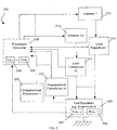
- FIG. 1 illustrates schematically the components of a system 100 for implementing aspects of the present invention described above.
- System 100 includes an actuator 110 for imparting loads and/or causing displacement of elements of a test specimen 120 such as an artificial knee.
- Actuator 110 may be a hydraulic, pneumatic, electromechanical device or combination thereof.
- the actuator(s) need support components such as servo-valves, accumulators, power sources, etc. as part of the system 100 but such components are not depicted here since such components are well known.
- a processor/controller 105 provides drive signals to the actuator 110 using load control or displacement control techniques.
- Processor/controller 105 may consist of analog and/or digital electronic configurations, with or without suitable software routines.
- the load transducer 115 and/or a position or displacement transducer 125 are operatively coupled to the test specimen 120 so as to sense loads and/or displacements in one or more degrees of freedom.
- the processor/controller 105 receives signals indicative of sensed loads or sensed displacements.
- the processor/controller 105 includes a mathematical model or representation 130 of simulated aspects of the test specimen 120 which herein represented as F( n ), as described above.
- the processor/controller 105 receives the actual measured loads and/or displacements from the load transducer 115 and the displacement transducer 125 and combines this information with simulated information in the model F( n ) 130.
- the actuator 110 is controlled by the processor/controller 105 as if the virtual (measured + simulated) loading and/or displacement had actually occurred.
- the actuator 110 can be appropriately controlled for repeated cycles wherein after, for example, a durability test, the test specimen 120 can be removed and wear characteristics measured.
- system 100 can be used for testing of an artificial knee or other prosthetic/Orthopedic implant.
- an artificial knee or other prosthetic/Orthopedic implant For example, assume it is desired to simulate the sliding between the two major components of the knee during articulation.
- a researcher may know the force input acting on the joint, for example, in a shearing direction, Anterior-Posterior, as well as the displacement of such components, aspects relative to the joint when soft tissues are present can complicate testing.
- Some approaches have included simulating soft tissue by mechanically applying springs between the two components. However, difficulties using this approach include choosing the right spring, locating it correctly, etc. Furthermore, proper modeling of soft tissue may not be accurate using a mechanical spring.
- an aspect of the present invention includes modeling or simulating a mechanical or other system such as the soft tissue as F( n ) 130 (e.g. in software), and using this representation as discussed above to control the actuator 110 as a function of the virtual (measured + simulated) loads and/or displacements.
- F( n ) can account for widely varying degrees of constraint and thereby widely varying specimen design.
- the test specimen such as an orthopedic or prosthetic implant
- the test specimen may include a microprocessor 135 and internal sensors for measuring force or other parameters, or detecting limits thereof, etc.
- An information signal from the microprocessor 135 can be used to control or change the control loop via the F(n) function.
- FIG. 2 illustrates another exemplary application similar to FIG. 1 in which a system 200 includes multiple actuators 210 and 212 for imparting loads and/or causing displacement of elements of a test specimen 220.
- a processor/controller 205 provides drive signals to multiple actuators, such as actuators 210 and 212, using load control or displacement control techniques.
- Load transducer 215 and 217 and position or displacement transducers 225 and 227 are operatively coupled to the test specimen 220 so as to sense loads or displacements in multiple degrees of freedom.
- the processor/controller 205 receives signals indicative of sensed loads and sensed displacements, while monitoring the result of multiple predetermined models, F( n ) 230 and F( n x ) 232.
- control logic may implement extended measurement capability on the same sample as its properties change over time or begin to degrade under extreme conditions.
- the test specimen such as a prosthetic implant
- the test specimen may include multiple microprocessors 235 and 237, and internal sensors for measuring force or other parameters, or detecting limits thereof, etc.
- An information signal from the multiple microprocessors 235 and 237 can be used to control or change the control loop via the F( n ) and F( n x ) functions.
Landscapes
- Health & Medical Sciences (AREA)
- Life Sciences & Earth Sciences (AREA)
- General Health & Medical Sciences (AREA)
- Biochemistry (AREA)
- Physics & Mathematics (AREA)
- Pathology (AREA)
- Immunology (AREA)
- General Physics & Mathematics (AREA)
- Orthopedic Medicine & Surgery (AREA)
- Analytical Chemistry (AREA)
- Transplantation (AREA)
- Chemical & Material Sciences (AREA)
- Vascular Medicine (AREA)
- Public Health (AREA)
- Veterinary Medicine (AREA)
- Physical Education & Sports Medicine (AREA)
- Animal Behavior & Ethology (AREA)
- Cardiology (AREA)
- Heart & Thoracic Surgery (AREA)
- Biomedical Technology (AREA)
- Engineering & Computer Science (AREA)
- Oral & Maxillofacial Surgery (AREA)
- Investigating Strength Of Materials By Application Of Mechanical Stress (AREA)
- Prostheses (AREA)
Description
- The present invention relates generally to durability testing of test specimens such as but not limited to, artificial orthopedic implants (e.g. hip, knee, spine, etc.). More specifically, the present invention pertains to a system and method for combining measured signals with virtual signals generated by a model to extend the range of mechanical methods of load testing.
- Laboratory simulation is a technique that is often used to validate the durability of orthopedic implant designs and to verify manufacturing quality assurance. In the case of the artificial knee joint, it is desirable to place the Anterior-Posterior and Tibial-Rotation degrees of freedom in load or torque control, while at the same time controlling the load in the vertical degree of freedom. Pure displacement control in these directions is deficient because it does not account for the changes in specimens over time or variation between specimen designs (e.g. levels of constraint). In addition, pure load control is made difficult by the variation in constraint levels between specimens and within a given specimen over its operating range (e.g. transitions from static to kinetic friction states, collision with hard mechanical limits built into the specimen, etc.). Previous research exists for the force inputs into the body, relative displacements expected in a healthy joint and the behavior of the surrounding soft tissue. It is also known that over time, as specimens wear, constraint levels and coefficients of friction change. It is not feasible to do long-term durability tests that incorporate all aspects of the in-vivo environment, such as, the living soft tissue. Therefore, commonly utilized test systems face an increasingly difficult task of applying forces to specimens that adequately emulate realistic conditions in addition to compensation techniques in the event of partial failure of the specimen. Design of simulators to apply varying loads is complicated by cross talk between channels and the continuously varying nature of each programmed load. Further difficulties arise from the large variation in implant design and the associated widely varying degrees of joint constraint.
- Once an artificial joint is implanted, it is constrained by a combination of mechanical interlock, frictional forces and the soft tissue surrounding the joint. The mechanical interlock and frictional forces may be directly replicated in the specimen, whereas the soft tissue is more difficult to simulate.
- Soft tissue reaction forces have been implemented in orthopedic simulators in the past by use of mechanical springs which have significant disadvantages including limited durability, difficulty in changing values, limited mathematical nature of the reaction forces, difficulty in attaining appropriate configuration and overall complexity of the machine.
-
- It is also known to adapt the coefficients of a control loop during a test. CLARKE D W: "Adaptive control of a materials-testing machine", 1996 IEE Colloquium, pages 1-4 discloses the adaptive control of load or displacement in load testing machines.
EP1219948 discloses the adaptive control of applied stress in a rheometer. Therefore, there is a significant need to improve systems that are used to test specimens for durability and other factors. A system that addresses one or more of the shortcomings discussed above would be particularly useful. - The invention provides a system and method to expand capabilities of simulation and durability testing of test specimens such as those exhibiting soft tissue behavior, as defined by the claims.
- According to the present invention, a virtual signal is generated by combining the actual measured signal from a transducer with a supplemental or simulated signal created by a function based on position, load or another known or measurable parameter. This virtual signal is then inserted into the control loop to adapt the system to this new, calculated or combined signal.
- Multiple virtual parameter thresholds can be used in the control loop described above such that when the threshold of one or more functions is met or exceeded, further actions may be enabled and subsequent functions may be implemented to further the testing.
-
-
FIG. 1 is a schematic diagram of a system for implementing a simplified embodiment of the present invention. -
FIG. 2 is schematic diagram illustrating a means for implementing multiple virtual models with various parameters of a more complex test system than that ofFIG. 1 . - This invention replaces the solely mechanical methods commonly used with software and hardware by incorporating a virtual model into the control loop and then controlling to this new, calculated virtual load and/or displacement. The virtual load and/or displacement signal is generated by a combination of the actual measured force from a transducer and a supplemental or simulated signal created by a mathematical or other derivable function based on known or measurable parameters (e.g. displacement, temperature, etc.), which exemplified below using "loads" can be represented as:

- A similar equation can be provided for systems operating under displacement control:

- This simulation function can be simply calculated real-time through the use of calculated control or expanded through the use of analog, digital or logical operators (such as `and', 'or', etc.), systems of linear or non-linear equations, look-up tables, static and dynamic system models, fuzzy logic, etc. For example, within a certain range function F(n) could be active, and if the resulting external influences cause a displacement, load or other parameter outside of that range, function F(n x) could be engaged.
-
FIG. 1 illustrates schematically the components of asystem 100 for implementing aspects of the present invention described above.System 100 includes anactuator 110 for imparting loads and/or causing displacement of elements of atest specimen 120 such as an artificial knee.Actuator 110 may be a hydraulic, pneumatic, electromechanical device or combination thereof. As appreciated by those skilled in the art, depending on the application, the actuator(s) need support components such as servo-valves, accumulators, power sources, etc. as part of thesystem 100 but such components are not depicted here since such components are well known. - A processor/
controller 105 provides drive signals to theactuator 110 using load control or displacement control techniques. Processor/controller 105 may consist of analog and/or digital electronic configurations, with or without suitable software routines. Theload transducer 115 and/or a position ordisplacement transducer 125 are operatively coupled to thetest specimen 120 so as to sense loads and/or displacements in one or more degrees of freedom. The processor/controller 105 receives signals indicative of sensed loads or sensed displacements. - As indicated above, the processor/
controller 105 includes a mathematical model orrepresentation 130 of simulated aspects of thetest specimen 120 which herein represented as F(n), as described above. The processor/controller 105 receives the actual measured loads and/or displacements from theload transducer 115 and thedisplacement transducer 125 and combines this information with simulated information in the model F(n) 130. Theactuator 110 is controlled by the processor/controller 105 as if the virtual (measured + simulated) loading and/or displacement had actually occurred. Thus, theactuator 110 can be appropriately controlled for repeated cycles wherein after, for example, a durability test, thetest specimen 120 can be removed and wear characteristics measured. - In a particularly useful application,
system 100 can be used for testing of an artificial knee or other prosthetic/Orthopedic implant. For example, assume it is desired to simulate the sliding between the two major components of the knee during articulation. Although from prior testing, a researcher may know the force input acting on the joint, for example, in a shearing direction, Anterior-Posterior, as well as the displacement of such components, aspects relative to the joint when soft tissues are present can complicate testing. Some approaches have included simulating soft tissue by mechanically applying springs between the two components. However, difficulties using this approach include choosing the right spring, locating it correctly, etc. Furthermore, proper modeling of soft tissue may not be accurate using a mechanical spring. For instance, characteristics of soft tissue may change with time, and thus, for testing an artificial knee, one may like to apply a test that takes the changes of soft tissue over time (aging, healing, etc.) into account as well as historical data from past test results. In addition, the mathematical function allows for the simulation of rate sensitive behavior (visco-elasticity) and insertion of specimen integrated microprocessor hardware into the test control loop. Therepresentation 130 can advantageously include this information. Thus, an aspect of the present invention includes modeling or simulating a mechanical or other system such as the soft tissue as F(n) 130 (e.g. in software), and using this representation as discussed above to control theactuator 110 as a function of the virtual (measured + simulated) loads and/or displacements. In addition, F(n) can account for widely varying degrees of constraint and thereby widely varying specimen design. - In a further embodiment, the test specimen, such as an orthopedic or prosthetic implant, may include a
microprocessor 135 and internal sensors for measuring force or other parameters, or detecting limits thereof, etc. An information signal from themicroprocessor 135 can be used to control or change the control loop via the F(n) function. -
FIG. 2 illustrates another exemplary application similar toFIG. 1 in which asystem 200 includesmultiple actuators test specimen 220. A processor/controller 205 provides drive signals to multiple actuators, such asactuators Load transducer displacement transducers test specimen 220 so as to sense loads or displacements in multiple degrees of freedom. The processor/controller 205 receives signals indicative of sensed loads and sensed displacements, while monitoring the result of multiple predetermined models, F(n) 230 and F(n x) 232. Signals frommultiple load transducers multiple displacement transducers models actuators system 200. In one aspect of such an embodiment, control logic may implement extended measurement capability on the same sample as its properties change over time or begin to degrade under extreme conditions. - In a further embodiment, the test specimen, such as a prosthetic implant, may include
multiple microprocessors multiple microprocessors - Although the present invention has been described with reference to preferred embodiments, workers skilled in the art will recognize that changes may be made in form and detail without departing from the scope of the invention.
Claims (13)
- A method for applying loads to an orthopedic test specimen, the method comprising:measuring loads and/or displacements on a test specimen;controlling an actuator coupled to the test specimen to apply at least one selected load on the test specimen by a control loop using a virtual load and/or displacement signal generated by the addition to the actual measured load and/or displacement signal of a supplemental signal created by a mathematical or other derivable function simulating the behavior of soft tissue surrounding a joint.
- The method of claim 1 wherein the supplemental signal includes parameters determined through historical data.
- The method of claim 1 wherein the supplemental signal includes more than one function.
- The method of claim 3 wherein the functions further comprise logical operators in order to engage additional functions.
- The method of claim 4 wherein the additional functions are engaged so as to allow uninterrupted test of the specimen.
- An orthopedic test system for applying loads to a test specimen, the system comprising: a controller;
an actuator operatively coupled to the controller to operate based on control signals therefrom and adapted to apply loads to an orthopedic test specimen;
at least one load transducer and/or at least one displacement transducer providing signals to the controller indicative of measured loads or displacements on the orthopedic test specimen; and
wherein the controller is adapted to control said actuator based on a virtual load and/or displacement signal generated by the addition to the actual measured load and/or displacement signal of a supplemental signal created by a mathematical or other derivable function simulating the behavior of soft tissue surrounding a joint. - The orthopedic test system of claim 6 wherein the controller controls the actuator based on input from the at least one load transducer within a predetermined linear operable range.
- The orthopedic test system of claim 6 wherein a predetermined representation of additional aspects of the orthopedic test specimen is determined according to historical measurement data.
- The orthopedic test system of claim 8 wherein the predetermined representation further comprises multiple parameters whereby more than one actuator is controlled by the controller based on the predetermined representation.
- The orthopedic test system of claim 8 wherein the controller is adapted to use more than one predetermined representation.
- The orthopedic test system of claim 10 wherein the predetermined representations further comprise logical operators in order to engage additional predetermined representations.
- The orthopedic test system of claim 11 wherein the engaging of the additional predetermined representations by use of logical operators allow uninterrupted test of the orthopedic test specimen.
- The orthopedic test system of claim 6 wherein the test specimen comprises one or more processors and one or more internal sensors.
Applications Claiming Priority (2)
| Application Number | Priority Date | Filing Date | Title |
|---|---|---|---|
| US52723203P | 2003-12-05 | 2003-12-05 | |
| PCT/US2004/040798 WO2005055888A1 (en) | 2003-12-05 | 2004-12-03 | A method to extend testing through integration of measured responses with virtual models |
Publications (2)
| Publication Number | Publication Date |
|---|---|
| EP1696838A1 EP1696838A1 (en) | 2006-09-06 |
| EP1696838B1 true EP1696838B1 (en) | 2018-09-19 |
Family
ID=34676719
Family Applications (1)
| Application Number | Title | Priority Date | Filing Date |
|---|---|---|---|
| EP04813159.3A Not-in-force EP1696838B1 (en) | 2003-12-05 | 2004-12-03 | Method and system to extend testing through integration of measured responses with virtual models |
Country Status (5)
| Country | Link |
|---|---|
| US (1) | US7383738B2 (en) |
| EP (1) | EP1696838B1 (en) |
| JP (1) | JP4808630B2 (en) |
| CN (1) | CN1901856B (en) |
| WO (1) | WO2005055888A1 (en) |
Families Citing this family (24)
| Publication number | Priority date | Publication date | Assignee | Title |
|---|---|---|---|---|
| US20080271542A1 (en) * | 2003-12-05 | 2008-11-06 | Mts Systems Corporation | Method to extend testing through integration of measured responses with virtual models |
| US7823460B2 (en) * | 2005-08-12 | 2010-11-02 | Advanced Mechanical Technology, Inc. | Prosthetic simulator with soft tissue modeling |
| US7762147B2 (en) | 2006-01-13 | 2010-07-27 | Mts Systems Corporation | Orthopedic simulator with integral load actuators |
| US7913573B2 (en) * | 2006-01-13 | 2011-03-29 | Mts Systems Corporation | Orthopedic simulator with a multi-axis slide table assembly |
| US7779708B2 (en) * | 2006-01-13 | 2010-08-24 | Mts Systems Corporation | Orthopedic simulator with fluid concentration maintenance arrangement for controlling fluid concentration of specimen baths |
| US7824184B2 (en) | 2006-01-13 | 2010-11-02 | Mts Systems Corporation | Integrated central manifold for orthopedic simulator |
| US7770446B2 (en) * | 2006-01-13 | 2010-08-10 | Mts Systems Corporation | Orthopedic simulator with temperature controller arrangement for controlling temperature of specimen baths |
| US20070260373A1 (en) * | 2006-05-08 | 2007-11-08 | Langer William J | Dynamic vehicle durability testing and simulation |
| US20070275355A1 (en) * | 2006-05-08 | 2007-11-29 | Langer William J | Integration and supervision for modeled and mechanical vehicle testing and simulation |
| KR20100021580A (en) * | 2007-05-04 | 2010-02-25 | 엠티에스 시스템즈 코포레이숀 | Method and system for tire evaluation and tuning with loading system and vehicle model |
| US20080275681A1 (en) * | 2007-05-04 | 2008-11-06 | Langer William J | Method and system for vehicle damper system evaluation and tuning with loading system and vehicle model |
| JP5248169B2 (en) * | 2008-04-01 | 2013-07-31 | 株式会社鷺宮製作所 | Loading test method and apparatus |
| US8135556B2 (en) | 2008-10-02 | 2012-03-13 | Mts Systems Corporation | Methods and systems for off-line control for simulation of coupled hybrid dynamic systems |
| US9477793B2 (en) | 2008-10-02 | 2016-10-25 | Mts Systems Corporation | Method and systems for off-line control for simulation of coupled hybrid dynamic systems |
| JP6061517B2 (en) * | 2012-06-27 | 2017-01-18 | 株式会社鷺宮製作所 | Test equipment |
| JP2016529527A (en) | 2013-09-09 | 2016-09-23 | エムティーエス システムズ コーポレイション | Method and system for testing coupled hybrid dynamic systems |
| WO2015035385A1 (en) | 2013-09-09 | 2015-03-12 | Mts Systems Corporation | Method of off-line hybrid system assessment for test monitoring and modification |
| US10531968B2 (en) * | 2014-05-23 | 2020-01-14 | Joseph Coggins | Prosthetic limb test apparatus and method |
| US10184864B2 (en) * | 2015-12-10 | 2019-01-22 | Mechanical Testing Services, Llc | Intelligent automated load control system and method |
| WO2019070659A1 (en) | 2017-10-03 | 2019-04-11 | Waters Technologies Corporation | Automatic system compliance estimation and correction for mechanical testing systems |
| WO2019074721A1 (en) | 2017-10-09 | 2019-04-18 | Waters Technologies Corporation | Determination of dynamic parameters for adaptive actuator control using a mechanical testing device |
| US11079308B2 (en) | 2017-10-09 | 2021-08-03 | Waters Technologies Corporation | Continuous determination of medium stiffness and load gain for adaptive actuator control |
| JP7448822B2 (en) | 2020-10-07 | 2024-03-13 | 日本製鉄株式会社 | Evaluation device and evaluation program |
| JP7448823B2 (en) | 2020-10-07 | 2024-03-13 | 日本製鉄株式会社 | Evaluation device and evaluation program |
Citations (1)
| Publication number | Priority date | Publication date | Assignee | Title |
|---|---|---|---|---|
| US6223604B1 (en) * | 1998-01-23 | 2001-05-01 | Wisconsin Alumni Research Foundation | Mobile truss testing apparatus |
Family Cites Families (27)
| Publication number | Priority date | Publication date | Assignee | Title |
|---|---|---|---|---|
| BE728819A (en) | 1968-02-26 | 1969-08-01 | ||
| DE2728007C2 (en) | 1977-06-22 | 1979-04-05 | Michael Dr. 7201 Rietheim Ungethuem | Simulator for testing total endoprostheses for the hip joint |
| US5014719A (en) | 1984-02-02 | 1991-05-14 | Mcleod Paul C | Knee loading and testing apparatus and method |
| US4882677A (en) | 1987-09-03 | 1989-11-21 | Curran Thomas M | Isometric strength testing method and equipment for disability evaluation |
| US5211666A (en) | 1991-04-22 | 1993-05-18 | New York University | Hip joint femoral component endoprosthesis with a lateral load-transferring support surface |
| GB9319788D0 (en) * | 1993-09-24 | 1993-11-10 | Instron Ltd | Structure testing machine |
| DE4411508C2 (en) * | 1994-04-02 | 2002-02-07 | Cerasiv Gmbh | Device for testing ceramic hip joint balls |
| JPH08285753A (en) | 1995-04-12 | 1996-11-01 | Bridgestone Corp | Thermal fatigue measuring method for viscoelastic body and servo flexometer |
| US5999168A (en) * | 1995-09-27 | 1999-12-07 | Immersion Corporation | Haptic accelerator for force feedback computer peripherals |
| JPH1011103A (en) * | 1996-06-27 | 1998-01-16 | Toyota Motor Corp | Control device for actuator and method for calculating feedback gain |
| JPH10185788A (en) * | 1996-12-27 | 1998-07-14 | Shimadzu Corp | Test device |
| US6171812B1 (en) | 1997-07-15 | 2001-01-09 | The National Institute Of Biogerontology, Inc. | Combined perfusion and mechanical loading system for explanted bone |
| US5937530A (en) * | 1997-11-26 | 1999-08-17 | Masson; Martin | Kinematic restraint device and method for determining the range of motion of a total knee replacement system |
| US6405145B1 (en) | 1998-03-20 | 2002-06-11 | National Instruments Corporation | Instrumentation system and method which performs instrument interchangeability checking |
| CA2350624A1 (en) | 1998-11-11 | 2000-05-18 | Kenmar Company Trust | Enhanced computer optimized adaptive suspension system and method |
| US6510740B1 (en) * | 1999-09-28 | 2003-01-28 | Rosemount Inc. | Thermal management in a pressure transmitter |
| JP3473834B2 (en) * | 1999-11-29 | 2003-12-08 | 株式会社安川電機 | Robot control device |
| US6538215B2 (en) | 2000-01-13 | 2003-03-25 | Sunbeam Products, Inc. | Programmable digital scale |
| US6571373B1 (en) | 2000-01-31 | 2003-05-27 | International Business Machines Corporation | Simulator-independent system-on-chip verification methodology |
| WO2001085402A2 (en) | 2000-05-12 | 2001-11-15 | Alberta Research Council Inc. | Motion platform with six linear electromagnetic actuators |
| JP2002062230A (en) * | 2000-08-21 | 2002-02-28 | Saginomiya Seisakusho Inc | Load testing method |
| US6721922B1 (en) | 2000-09-27 | 2004-04-13 | Cadence Design Systems, Inc. | System for electronic circuit characterization, analysis, modeling and plan development |
| US6598486B2 (en) * | 2001-05-21 | 2003-07-29 | Enduratec Systems Corporation | Portable device for testing the shear response of a material in response to a repetitive applied force |
| DE10139333A1 (en) | 2001-08-10 | 2003-03-06 | Biedermann Motech Gmbh | Sensor device, in particular for a prosthesis and prosthesis with such a sensor device |
| WO2003079940A2 (en) | 2002-03-19 | 2003-10-02 | The Board Of Trustees Of The University Of Illinois | System and method for prosthetic fitting and balancing in joints |
| US6821299B2 (en) | 2002-07-24 | 2004-11-23 | Zimmer Technology, Inc. | Implantable prosthesis for measuring six force components |
| US6715336B1 (en) * | 2003-02-24 | 2004-04-06 | Npoint, Inc. | Piezoelectric force motion scanner |
-
2004
- 2004-12-03 WO PCT/US2004/040798 patent/WO2005055888A1/en active Application Filing
- 2004-12-03 US US11/004,308 patent/US7383738B2/en active Active
- 2004-12-03 CN CN2004800403651A patent/CN1901856B/en not_active Expired - Fee Related
- 2004-12-03 JP JP2006542861A patent/JP4808630B2/en not_active Expired - Fee Related
- 2004-12-03 EP EP04813159.3A patent/EP1696838B1/en not_active Not-in-force
Patent Citations (1)
| Publication number | Priority date | Publication date | Assignee | Title |
|---|---|---|---|---|
| US6223604B1 (en) * | 1998-01-23 | 2001-05-01 | Wisconsin Alumni Research Foundation | Mobile truss testing apparatus |
Also Published As
| Publication number | Publication date |
|---|---|
| WO2005055888A1 (en) | 2005-06-23 |
| US20050120802A1 (en) | 2005-06-09 |
| JP2007518070A (en) | 2007-07-05 |
| EP1696838A1 (en) | 2006-09-06 |
| CN1901856A (en) | 2007-01-24 |
| JP4808630B2 (en) | 2011-11-02 |
| CN1901856B (en) | 2010-12-01 |
| US7383738B2 (en) | 2008-06-10 |
Similar Documents
| Publication | Publication Date | Title |
|---|---|---|
| EP1696838B1 (en) | Method and system to extend testing through integration of measured responses with virtual models | |
| US20080271542A1 (en) | Method to extend testing through integration of measured responses with virtual models | |
| JP5698757B2 (en) | System and method for joint motion simulation | |
| Pappalardo et al. | Hunt–Crossley model based force control for minimally invasive robotic surgery | |
| Hwang | Identification techniques of structure connection parameters using frequency response functions | |
| US20070051180A1 (en) | Prosthetic simulator with soft tissue modeling | |
| Chanthasopeephan et al. | Measuring forces in liver cutting: New equipment and experimental results | |
| Guo et al. | Iterative learning based output feedback control for electro-hydraulic loading system of a gait simulator | |
| Halsne et al. | Emulating the effective ankle stiffness of commercial prosthetic feet using a robotic prosthetic foot emulator | |
| Meaney | Mechanical properties of implantable biomaterials | |
| Vechet et al. | Hydraulic arm modeling via matlab simhydraulics | |
| Aloisio et al. | Computer-based simulator for catheter insertion training | |
| Marinelli | Design, development and engineering of a bench for testing lower limb prosthesis, with focus on high-technological solutions | |
| Marinelli et al. | In vitro test method for the development of intelligent lower limb prosthetic devices | |
| Zhang | Biomechanical realism versus algorithmic efficiency: A trade-off in human motion simulation modeling | |
| Torabnia et al. | Design and manufacturing of a hip joint motion simulator with a novel modular design approach | |
| EP3623885A1 (en) | Method for haptic testing of an object | |
| Fujino et al. | Displaying feeling of cutting by a micro-scissors type haptic device | |
| Creuillot et al. | Mechatronic Design Towards Investigation of the Temporo-Mandibular Joint Behaviour | |
| Azimaee et al. | Calibration of an Instrumented Surgical Forceps Using Bootstrap Technique: a Comparative Study | |
| Ivanova et al. | Experimental studies of the structure of biological tissues through mechanical effects with a smart laparoscopic instrument | |
| Chanthasopeephan | Characterization of soft tissue cutting for haptic display: Experiments and computational models | |
| Lister et al. | Real-time, haptics-enabled simulator for probing ex vivo liver tissue | |
| Marinelli et al. | Design and control of an active humanoid leg for testing lower-limb prostheses | |
| Liu | Integrated Screw-Hook Development |
Legal Events
| Date | Code | Title | Description |
|---|---|---|---|
| PUAI | Public reference made under article 153(3) epc to a published international application that has entered the european phase |
Free format text: ORIGINAL CODE: 0009012 |
|
| 17P | Request for examination filed |
Effective date: 20060628 |
|
| AK | Designated contracting states |
Kind code of ref document: A1 Designated state(s): AT BE BG CH CY CZ DE DK EE ES FI FR GB GR HU IE IS IT LI LT LU MC NL PL PT RO SE SI SK TR |
|
| DAX | Request for extension of the european patent (deleted) | ||
| 17Q | First examination report despatched |
Effective date: 20101119 |
|
| GRAP | Despatch of communication of intention to grant a patent |
Free format text: ORIGINAL CODE: EPIDOSNIGR1 |
|
| INTG | Intention to grant announced |
Effective date: 20180403 |
|
| GRAS | Grant fee paid |
Free format text: ORIGINAL CODE: EPIDOSNIGR3 |
|
| GRAA | (expected) grant |
Free format text: ORIGINAL CODE: 0009210 |
|
| AK | Designated contracting states |
Kind code of ref document: B1 Designated state(s): AT BE BG CH CY CZ DE DK EE ES FI FR GB GR HU IE IS IT LI LT LU MC NL PL PT RO SE SI SK TR |
|
| REG | Reference to a national code |
Ref country code: GB Ref legal event code: FG4D |
|
| REG | Reference to a national code |
Ref country code: CH Ref legal event code: EP |
|
| REG | Reference to a national code |
Ref country code: DE Ref legal event code: R096 Ref document number: 602004053208 Country of ref document: DE |
|
| REG | Reference to a national code |
Ref country code: AT Ref legal event code: REF Ref document number: 1042374 Country of ref document: AT Kind code of ref document: T Effective date: 20181015 |
|
| REG | Reference to a national code |
Ref country code: IE Ref legal event code: FG4D |
|
| REG | Reference to a national code |
Ref country code: CH Ref legal event code: NV Representative=s name: VOSSIUS AND PARTNER PATENTANWAELTE RECHTSANWAE, CH |
|
| REG | Reference to a national code |
Ref country code: NL Ref legal event code: MP Effective date: 20180919 |
|
| PG25 | Lapsed in a contracting state [announced via postgrant information from national office to epo] |
Ref country code: GR Free format text: LAPSE BECAUSE OF FAILURE TO SUBMIT A TRANSLATION OF THE DESCRIPTION OR TO PAY THE FEE WITHIN THE PRESCRIBED TIME-LIMIT Effective date: 20181220 Ref country code: LT Free format text: LAPSE BECAUSE OF FAILURE TO SUBMIT A TRANSLATION OF THE DESCRIPTION OR TO PAY THE FEE WITHIN THE PRESCRIBED TIME-LIMIT Effective date: 20180919 Ref country code: FI Free format text: LAPSE BECAUSE OF FAILURE TO SUBMIT A TRANSLATION OF THE DESCRIPTION OR TO PAY THE FEE WITHIN THE PRESCRIBED TIME-LIMIT Effective date: 20180919 Ref country code: SE Free format text: LAPSE BECAUSE OF FAILURE TO SUBMIT A TRANSLATION OF THE DESCRIPTION OR TO PAY THE FEE WITHIN THE PRESCRIBED TIME-LIMIT Effective date: 20180919 Ref country code: BG Free format text: LAPSE BECAUSE OF FAILURE TO SUBMIT A TRANSLATION OF THE DESCRIPTION OR TO PAY THE FEE WITHIN THE PRESCRIBED TIME-LIMIT Effective date: 20181219 |
|
| REG | Reference to a national code |
Ref country code: LT Ref legal event code: MG4D |
|
| REG | Reference to a national code |
Ref country code: AT Ref legal event code: MK05 Ref document number: 1042374 Country of ref document: AT Kind code of ref document: T Effective date: 20180919 |
|
| PG25 | Lapsed in a contracting state [announced via postgrant information from national office to epo] |
Ref country code: RO Free format text: LAPSE BECAUSE OF FAILURE TO SUBMIT A TRANSLATION OF THE DESCRIPTION OR TO PAY THE FEE WITHIN THE PRESCRIBED TIME-LIMIT Effective date: 20180919 Ref country code: CZ Free format text: LAPSE BECAUSE OF FAILURE TO SUBMIT A TRANSLATION OF THE DESCRIPTION OR TO PAY THE FEE WITHIN THE PRESCRIBED TIME-LIMIT Effective date: 20180919 Ref country code: EE Free format text: LAPSE BECAUSE OF FAILURE TO SUBMIT A TRANSLATION OF THE DESCRIPTION OR TO PAY THE FEE WITHIN THE PRESCRIBED TIME-LIMIT Effective date: 20180919 Ref country code: AT Free format text: LAPSE BECAUSE OF FAILURE TO SUBMIT A TRANSLATION OF THE DESCRIPTION OR TO PAY THE FEE WITHIN THE PRESCRIBED TIME-LIMIT Effective date: 20180919 Ref country code: PL Free format text: LAPSE BECAUSE OF FAILURE TO SUBMIT A TRANSLATION OF THE DESCRIPTION OR TO PAY THE FEE WITHIN THE PRESCRIBED TIME-LIMIT Effective date: 20180919 Ref country code: NL Free format text: LAPSE BECAUSE OF FAILURE TO SUBMIT A TRANSLATION OF THE DESCRIPTION OR TO PAY THE FEE WITHIN THE PRESCRIBED TIME-LIMIT Effective date: 20180919 Ref country code: ES Free format text: LAPSE BECAUSE OF FAILURE TO SUBMIT A TRANSLATION OF THE DESCRIPTION OR TO PAY THE FEE WITHIN THE PRESCRIBED TIME-LIMIT Effective date: 20180919 Ref country code: IS Free format text: LAPSE BECAUSE OF FAILURE TO SUBMIT A TRANSLATION OF THE DESCRIPTION OR TO PAY THE FEE WITHIN THE PRESCRIBED TIME-LIMIT Effective date: 20190119 |
|
| PG25 | Lapsed in a contracting state [announced via postgrant information from national office to epo] |
Ref country code: PT Free format text: LAPSE BECAUSE OF FAILURE TO SUBMIT A TRANSLATION OF THE DESCRIPTION OR TO PAY THE FEE WITHIN THE PRESCRIBED TIME-LIMIT Effective date: 20190119 Ref country code: SK Free format text: LAPSE BECAUSE OF FAILURE TO SUBMIT A TRANSLATION OF THE DESCRIPTION OR TO PAY THE FEE WITHIN THE PRESCRIBED TIME-LIMIT Effective date: 20180919 |
|
| REG | Reference to a national code |
Ref country code: DE Ref legal event code: R097 Ref document number: 602004053208 Country of ref document: DE |
|
| PLBE | No opposition filed within time limit |
Free format text: ORIGINAL CODE: 0009261 |
|
| STAA | Information on the status of an ep patent application or granted ep patent |
Free format text: STATUS: NO OPPOSITION FILED WITHIN TIME LIMIT |
|
| PG25 | Lapsed in a contracting state [announced via postgrant information from national office to epo] |
Ref country code: DK Free format text: LAPSE BECAUSE OF FAILURE TO SUBMIT A TRANSLATION OF THE DESCRIPTION OR TO PAY THE FEE WITHIN THE PRESCRIBED TIME-LIMIT Effective date: 20180919 |
|
| 26N | No opposition filed |
Effective date: 20190620 |
|
| GBPC | Gb: european patent ceased through non-payment of renewal fee |
Effective date: 20181219 |
|
| PG25 | Lapsed in a contracting state [announced via postgrant information from national office to epo] |
Ref country code: LU Free format text: LAPSE BECAUSE OF NON-PAYMENT OF DUE FEES Effective date: 20181203 Ref country code: MC Free format text: LAPSE BECAUSE OF FAILURE TO SUBMIT A TRANSLATION OF THE DESCRIPTION OR TO PAY THE FEE WITHIN THE PRESCRIBED TIME-LIMIT Effective date: 20180919 |
|
| REG | Reference to a national code |
Ref country code: IE Ref legal event code: MM4A |
|
| REG | Reference to a national code |
Ref country code: BE Ref legal event code: MM Effective date: 20181231 |
|
| PG25 | Lapsed in a contracting state [announced via postgrant information from national office to epo] |
Ref country code: IE Free format text: LAPSE BECAUSE OF NON-PAYMENT OF DUE FEES Effective date: 20181203 Ref country code: SI Free format text: LAPSE BECAUSE OF FAILURE TO SUBMIT A TRANSLATION OF THE DESCRIPTION OR TO PAY THE FEE WITHIN THE PRESCRIBED TIME-LIMIT Effective date: 20180919 |
|
| PG25 | Lapsed in a contracting state [announced via postgrant information from national office to epo] |
Ref country code: BE Free format text: LAPSE BECAUSE OF NON-PAYMENT OF DUE FEES Effective date: 20181231 |
|
| PG25 | Lapsed in a contracting state [announced via postgrant information from national office to epo] |
Ref country code: GB Free format text: LAPSE BECAUSE OF NON-PAYMENT OF DUE FEES Effective date: 20181219 |
|
| PGFP | Annual fee paid to national office [announced via postgrant information from national office to epo] |
Ref country code: IT Payment date: 20191219 Year of fee payment: 16 Ref country code: FR Payment date: 20191226 Year of fee payment: 16 |
|
| PG25 | Lapsed in a contracting state [announced via postgrant information from national office to epo] |
Ref country code: TR Free format text: LAPSE BECAUSE OF FAILURE TO SUBMIT A TRANSLATION OF THE DESCRIPTION OR TO PAY THE FEE WITHIN THE PRESCRIBED TIME-LIMIT Effective date: 20180919 |
|
| PGFP | Annual fee paid to national office [announced via postgrant information from national office to epo] |
Ref country code: DE Payment date: 20191231 Year of fee payment: 16 |
|
| PGFP | Annual fee paid to national office [announced via postgrant information from national office to epo] |
Ref country code: CH Payment date: 20191231 Year of fee payment: 16 |
|
| PG25 | Lapsed in a contracting state [announced via postgrant information from national office to epo] |
Ref country code: HU Free format text: LAPSE BECAUSE OF FAILURE TO SUBMIT A TRANSLATION OF THE DESCRIPTION OR TO PAY THE FEE WITHIN THE PRESCRIBED TIME-LIMIT; INVALID AB INITIO Effective date: 20041203 Ref country code: CY Free format text: LAPSE BECAUSE OF FAILURE TO SUBMIT A TRANSLATION OF THE DESCRIPTION OR TO PAY THE FEE WITHIN THE PRESCRIBED TIME-LIMIT Effective date: 20180919 |
|
| REG | Reference to a national code |
Ref country code: DE Ref legal event code: R119 Ref document number: 602004053208 Country of ref document: DE |
|
| REG | Reference to a national code |
Ref country code: CH Ref legal event code: PL |
|
| PG25 | Lapsed in a contracting state [announced via postgrant information from national office to epo] |
Ref country code: FR Free format text: LAPSE BECAUSE OF NON-PAYMENT OF DUE FEES Effective date: 20201231 Ref country code: IT Free format text: LAPSE BECAUSE OF NON-PAYMENT OF DUE FEES Effective date: 20201203 |
|
| PG25 | Lapsed in a contracting state [announced via postgrant information from national office to epo] |
Ref country code: LI Free format text: LAPSE BECAUSE OF NON-PAYMENT OF DUE FEES Effective date: 20201231 Ref country code: DE Free format text: LAPSE BECAUSE OF NON-PAYMENT OF DUE FEES Effective date: 20210701 Ref country code: CH Free format text: LAPSE BECAUSE OF NON-PAYMENT OF DUE FEES Effective date: 20201231 |