EP1691470A1 - Synchronous electric motor particulary for washing machines and similar household appliances and relevant assembling method - Google Patents
Synchronous electric motor particulary for washing machines and similar household appliances and relevant assembling method Download PDFInfo
- Publication number
- EP1691470A1 EP1691470A1 EP05425068A EP05425068A EP1691470A1 EP 1691470 A1 EP1691470 A1 EP 1691470A1 EP 05425068 A EP05425068 A EP 05425068A EP 05425068 A EP05425068 A EP 05425068A EP 1691470 A1 EP1691470 A1 EP 1691470A1
- Authority
- EP
- European Patent Office
- Prior art keywords
- stator
- electric motor
- motor according
- heat sink
- elements
- Prior art date
- Legal status (The legal status is an assumption and is not a legal conclusion. Google has not performed a legal analysis and makes no representation as to the accuracy of the status listed.)
- Granted
Links
- 230000001360 synchronised effect Effects 0.000 title claims abstract description 22
- 238000000034 method Methods 0.000 title claims description 14
- 238000005406 washing Methods 0.000 title description 2
- 238000004804 winding Methods 0.000 claims abstract description 7
- 125000006850 spacer group Chemical group 0.000 claims description 8
- 238000003780 insertion Methods 0.000 claims description 2
- 230000037431 insertion Effects 0.000 claims description 2
- 238000012423 maintenance Methods 0.000 description 2
- 238000000926 separation method Methods 0.000 description 2
- 230000005540 biological transmission Effects 0.000 description 1
- 238000001816 cooling Methods 0.000 description 1
Images


Classifications
-
- D—TEXTILES; PAPER
- D06—TREATMENT OF TEXTILES OR THE LIKE; LAUNDERING; FLEXIBLE MATERIALS NOT OTHERWISE PROVIDED FOR
- D06F—LAUNDERING, DRYING, IRONING, PRESSING OR FOLDING TEXTILE ARTICLES
- D06F37/00—Details specific to washing machines covered by groups D06F21/00 - D06F25/00
- D06F37/30—Driving arrangements
- D06F37/304—Arrangements or adaptations of electric motors
-
- H—ELECTRICITY
- H02—GENERATION; CONVERSION OR DISTRIBUTION OF ELECTRIC POWER
- H02K—DYNAMO-ELECTRIC MACHINES
- H02K11/00—Structural association of dynamo-electric machines with electric components or with devices for shielding, monitoring or protection
- H02K11/30—Structural association with control circuits or drive circuits
- H02K11/33—Drive circuits, e.g. power electronics
-
- H—ELECTRICITY
- H02—GENERATION; CONVERSION OR DISTRIBUTION OF ELECTRIC POWER
- H02K—DYNAMO-ELECTRIC MACHINES
- H02K29/00—Motors or generators having non-mechanical commutating devices, e.g. discharge tubes or semiconductor devices
- H02K29/06—Motors or generators having non-mechanical commutating devices, e.g. discharge tubes or semiconductor devices with position sensing devices
- H02K29/08—Motors or generators having non-mechanical commutating devices, e.g. discharge tubes or semiconductor devices with position sensing devices using magnetic effect devices, e.g. Hall-plates, magneto-resistors
-
- Y—GENERAL TAGGING OF NEW TECHNOLOGICAL DEVELOPMENTS; GENERAL TAGGING OF CROSS-SECTIONAL TECHNOLOGIES SPANNING OVER SEVERAL SECTIONS OF THE IPC; TECHNICAL SUBJECTS COVERED BY FORMER USPC CROSS-REFERENCE ART COLLECTIONS [XRACs] AND DIGESTS
- Y10—TECHNICAL SUBJECTS COVERED BY FORMER USPC
- Y10T—TECHNICAL SUBJECTS COVERED BY FORMER US CLASSIFICATION
- Y10T29/00—Metal working
- Y10T29/49—Method of mechanical manufacture
- Y10T29/49002—Electrical device making
- Y10T29/49009—Dynamoelectric machine
Definitions
- the present invention refers, in its most general aspect, to a synchronous electric motor for washing-machines and similar household appliances with rotary drum.
- the synchronous electric motor according to the invention is of the type comprising an inner stator having stator windings mounted fixed on a central axis, an electronic control board electrically connected to the stator, and a heat sink element associated with the electronic board.
- the present invention also concerns an assembly method of the aforementioned synchronous electric motor.
- washing-machines are equipped with a washing tank inside which a rotary drum that is cylindrical in shape and that can be accessed through a door of the washing-machine to load the laundry to be washed is activated.
- the rotary drum of the washing-machines is actuated in rotation by electric motors structured with an inner stator which is fixed to an axis, and an outer rotor that surrounds the stator.
- the drum of the washing-machine is kinematically connected to the rotor through suitable pulleys and a transmission belt.
- the operation of the synchronous electric motor is also normally controlled by a specific electronic board that adjusts its operation, and it is also electrically connected to the main board of the washing-machine.
- the synchronous electric motor and the respective electronic board for controlling it are set apart from one another.
- the electric motor is positioned in one area of the washing-machine whilst the electronic board is arranged in a separate area close to the main board and is connected to the electric motor through determined wiring.
- This separation is mainly due to the need to arrange one or more heat sink devices in a single area of the washing-machine where the electronics are arranged and that can possibly be cooled with ease.
- the large amount of wiring involves greater maintenance costs of the electric motor in case of failure.
- the technical problem underlying the present invention is therefore that of providing a synchronous electric motor, for washing-machines and similar household appliances, having such a structure as to allow ease of assembly and, at the same time, a reduction of the wiring for the connection of the electronic control board.
- the invention also concerns a synchronous electric motor as defined by claim 23.
- the invention also concerns a method for assembling an electric motor with outer rotor and inner stator as defined by claim 27.
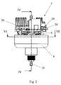
- 1 schematically indicates a washing-machine with a rotary drum 2, for which a synchronous electric motor 3 according to the present invention is used.
- This electric motor is of the so-called inner stator and outer rotor type, in other words of the type wherein the rotor 4 is mounted outside the respective stator 5.
- the motor 3 is kinematically connected, in a conventional way per se, to the rotary drum 2 of the washing-machine 1 through a belt and pulley connection 7 visible in figure 1.
- the stator 5 has, in the case of the illustrated solution (figures 2, 3 and 4), a substantially cylindrical configuration, and it comprises a plurality of per se known pole pieces 6 each defined by a corresponding plurality of identical plates 9, pack-like arranged on top of each other, in mutual contact and mounted fixed on a central axis 10.
- the pole pieces 6 are contained and supported by a frame 8 of the stator 5 made of two substantially plate-like elements 12 and 13, respectively.
- the two plate-like elements 12, 13 are arranged on opposite sides, for example above and respectively below the pole pieces 6.
- the stator 5 has, in a per se known way, an axial passage 15, also substantially cylindrical, of predetermined diameter, or prismatic, and intended to be engaged by the axis 10.
- the synchronous electric motor 3 also comprises an electronic control board 18 electrically connected to the motor itself and a heat sink element 20 associated with the electronic board 18.
- the electronic board 18 is per se known, like the heat sink element 20 which has a foil-like configuration with a large heat exchange surface.
- the heat sink element 20 is mounted on the stator 5 in an axial extension thereof with a predetermined spaced relation therefrom.
- the electronic control board 18 is supported by the heat sink element 20, on a side thereof facing the stator 5.
- the electronic control board 18 is fixed to the heat sink element 20 and it is arranged on a side of this latter so as to be on the side facing the stator 5 and close to this latter to obtain an electric connection having reduced wiring.
- the electronic board 18 is supported by the heat sink 20 in an intermediate position between this latter and the stator 5.
- the heat sink element 20 is mounted above the stator 5 at a selected distance so as to allow the interposition of the electronic board 18.
- the electronic board 18 is housed in a recess 21 formed on the aforementioned side of the heat sink element 20 facing the stator 5.
- the synchronous electric motor 3 comprises first connector elements 22 of the board 18 projecting towards the stator 5 and second connector elements 24 of the stator 5 projecting towards the board 18.
- the first and second connector elements 22 and 24, respectively are connectors of the male/female clutch type, such as fastom connectors.
- the first and second connectors 22 and 24 are arranged in a substantially central area of the motor 3 about the axis 10, so as to be completely protected between the stator 5 and the heat sink 20.
- the first and second connector elements 22 and 24 are respectively aligned substantially along a circumference portion about the axis 10 (see figures 3 and 5), in particular in the case of the illustrated solution along the right circumference portion. This allows a connection univocality to be obtained between the electronic board 18 and the stator 5, without the risk of a mistaken electric connection.
- the heat sink 20 is fixed directly onto the frame 8 of the stator 5 through locking screws 30.
- the locking screws 30 can be screwed from outside the electric motor 3 so as to ease the fixing operations.
- the sink element 20 comprises guides 32 to guide the insertion from the outside of the clamping screws 30 as well as the access of a tool for their screwing.
- the electric motor 3 also comprises a plurality of first positioning elements 35 to guide and position the heat sink element 20 in a predetermined angular position on the frame 8 of the stator 5.
- the first positioning elements 35 internally comprise hollow bushings (figure 7), wherein the clamping screws 30 are suitable to be screwed.
- the first positioning elements 35 are aligned along a circumference around the axis 10 and with a predetermined angular relationship with respect to each other.
- the first positioning elements 35 are three and they are arranged at 120° from one another with respect to the central axis 10.
- the first positioning elements 35 are arranged substantially parallel to the axis 10 and they are integrally made with the plate-like element 12 of the frame 8 of the stator 5.
- the electric motor 3 comprises spacer elements 40 to adjust the distance of the heat sink 20 from the stator 5.
- the spacers 40 are internally hollow and they are axially aligned with the first positioning elements 35.
- the spacer elements 40 are integrally made with the heat sink 20 and they have are tubular shape, to allow the clamping screws 30 to pass.
- the sink 20 also comprises second positioning elements 42 for adjusting the fixing position of the electronic board 18.
- the second positioning elements 42 comprise internally hollow bushings 44, wherein corresponding clamping screws 46 are suitable to be screwed.
- the synchronous electric motor 3 comprises a support 50 for magnetic field sensors 48, which is axially interposed between the electronic board 18 and the frame 18 of the stator 5.
- the support 50 comprises a disc-like element 51 (figure 5) whereon a plurality of substantially glass-like elements 52 are fixed, which are arranged with the mouth facing the electronic board 18.
- the elements 52 define corresponding seats for housing magnetic field sensors 48, such as Hall sensors.
- the magnetic field sensors 48 are integrally connected to the electronic board 18, they project from this latter according to a direction parallel to the axis 10 so as to be retractably inserted inside the respective support seats 50.
- the stator 5 comprises, between the stator windings 9, a plurality of cavities (figure 6), which are suitable to retractably receive the glass-like elements 52 of the support 50 including the respective sensors 48.
- a synchronous electric motor according to the invention is assembled through an assembly method also object of the present invention.
- the method comprises the steps of
- the assembly method according to the invention provides fixing, first, the electronic board 18 on the heat sink 20 on one side of this latter, and then mounting the heat sink 20 so that the electronic board 18 is on the side facing the stator 5 close to this latter.
- the electronic board 18 is thus arranged between the stator 5 and the heat sink 20.
- the method according to the invention comprises a further step wherein the electronic board 18 is provided with first connector elements 22 projecting towards the stator 5 and the stator 5 is provided with second connector elements 24 projecting towards the electronic board 18.
- the first and second connector elements 22, 24 are electrically interconnected through direct clutch when the sink 20 and the electronic board 18 are mounted on the stator 5.
- this allows the electronic board 18 to be electrically connected through the respective connectors 22 and 24 to the stator 5, at the time when the sink is mechanically fixed onto the stator 5.
- the heat sink 20 is fixed from outside the motor 3 onto a frame of the stator 5 through clamping screws 30.
- a support 50 for magnetic field sensors 48 is mounted on the stator 5, so as to be arranged between the stator 5 and the electronic board 18.
- the main advantage of the synchronous electric motor according to the invention lies in that it allows easy assembly of the electronics on the stator, thus allowing an easy connection of the electronic board to the stator and a substantial reduction of the wiring.
- a further advantage is that the electronic board can be connected directly to the stator through the relative clutch connectors, when the sink is fixed onto the stator.
- the axial arrangement of the heat sink on the stator also allows a globally compact motor to be obtained.
- the provision of arranging the electronic board in the relative recess formed in the heat sink is also particularly advantageous. This allows the electronic board 18 to be protected during assembly.
- the interposition of the support of the magnetic field sensors between the stator and the electronic board also allows the assembly of the sensors to be simplified and a space reduction to be obtained.
- the retractable arrangement of the sensors between the stator windings besides reducing the spaces, allows the sensors to be advantageously protected.
- bushings which also have the function of screwing seats of the clamping screws, as positioning elements is also advantageous.
- the spacer elements also have the advantage of adjusting the axial position of the heat sink with respect to the stator so as to allow the sensors to be positioned between the electronic board and the support.
- the spacer elements realised in a tubular shape and aligned with the positioning elements also have the advantage of acting as passage seat and guide for the clamping screws.
Landscapes
- Engineering & Computer Science (AREA)
- Power Engineering (AREA)
- Microelectronics & Electronic Packaging (AREA)
- Textile Engineering (AREA)
- Control Of Washing Machine And Dryer (AREA)
- Control Of Motors That Do Not Use Commutators (AREA)
- Permanent Magnet Type Synchronous Machine (AREA)
- Motor Or Generator Cooling System (AREA)
- Motor Or Generator Frames (AREA)
Abstract
Description
- The present invention refers, in its most general aspect, to a synchronous electric motor for washing-machines and similar household appliances with rotary drum.
- In particular, the synchronous electric motor according to the invention is of the type comprising an inner stator having stator windings mounted fixed on a central axis, an electronic control board electrically connected to the stator, and a heat sink element associated with the electronic board.
- The present invention also concerns an assembly method of the aforementioned synchronous electric motor.
- As it is well known to the skilled in the art, household washing-machines are equipped with a washing tank inside which a rotary drum that is cylindrical in shape and that can be accessed through a door of the washing-machine to load the laundry to be washed is activated.
- Normally, the rotary drum of the washing-machines is actuated in rotation by electric motors structured with an inner stator which is fixed to an axis, and an outer rotor that surrounds the stator.
- The drum of the washing-machine is kinematically connected to the rotor through suitable pulleys and a transmission belt.
- The operation of the synchronous electric motor is also normally controlled by a specific electronic board that adjusts its operation, and it is also electrically connected to the main board of the washing-machine.
- Generally, in a washing-machine, the synchronous electric motor and the respective electronic board for controlling it are set apart from one another. In practice, the electric motor is positioned in one area of the washing-machine whilst the electronic board is arranged in a separate area close to the main board and is connected to the electric motor through determined wiring.
- This separation is mainly due to the need to arrange one or more heat sink devices in a single area of the washing-machine where the electronics are arranged and that can possibly be cooled with ease.
- However, it is clear that this separation requires a complex wiring to connect the electronic board with the relative electric motor and also makes also the assembly of the electric motor difficult.
- Moreover, the large amount of wiring involves greater maintenance costs of the electric motor in case of failure.
- It has also been proposed to integrate the control board inside the motor, this however at the expense of a high cost to modify the trim of the motor itself and allow the electronic board to be housed, as well as to obtain its effective cooling.
- The technical problem underlying the present invention is therefore that of providing a synchronous electric motor, for washing-machines and similar household appliances, having such a structure as to allow ease of assembly and, at the same time, a reduction of the wiring for the connection of the electronic control board.
- This technical problem is solved, according to the present invention, by a synchronous electric motor of the aforementioned type wherein the heat sink element is mounted on the stator in an axial extension thereof and spaced therefrom, and wherein the electronic control board is supported on the heat sink on a side facing the stator.
- The invention also concerns a synchronous electric motor as defined by claim 23.
- The invention also concerns a method for assembling an electric motor with outer rotor and inner stator as defined by claim 27.
- Further characteristics and advantages of the motor and of the assembly method according to the invention will become apparent from the following description of an embodiment thereof, with reference to the attached drawings, given by way of indicative and non limiting example.
- In the drawings:
- Figure 1 schematically represents a washing-machine incorporating a synchronous electric motor according to the present invention.
- Figure 2 illustrates a view of the synchronous electric motor according to the present invention.
- Figure 3 illustrates the synchronous electric motor according to the present invention with separated parts.
- Figure 4 illustrates a section of the synchronous electric motor according to the line IV-IV of figure 2.
- Figure 5 illustrates the enlarged detail indicated with V in figure 3.
- Figure 6 indicates a section view of the synchronous electric motor according to the line VI-VI of figure 2.
- Figure 7 indicates an enlarged detail of figure 4.
- With reference to figure 1, 1 schematically indicates a washing-machine with a
rotary drum 2, for which a synchronouselectric motor 3 according to the present invention is used. This electric motor is of the so-called inner stator and outer rotor type, in other words of the type wherein therotor 4 is mounted outside therespective stator 5. - In the case of the illustrated solution, the
motor 3 is kinematically connected, in a conventional way per se, to therotary drum 2 of the washing-machine 1 through a belt and pulley connection 7 visible in figure 1. - On its whole, the
stator 5 has, in the case of the illustrated solution (figures 2, 3 and 4), a substantially cylindrical configuration, and it comprises a plurality of per se knownpole pieces 6 each defined by a corresponding plurality ofidentical plates 9, pack-like arranged on top of each other, in mutual contact and mounted fixed on acentral axis 10. - In the case of the illustrated solution, the
pole pieces 6 are contained and supported by aframe 8 of thestator 5 made of two substantially plate-like elements - The two plate-
like elements pole pieces 6. - For the fixing to the
central axis 10, thestator 5 has, in a per se known way, anaxial passage 15, also substantially cylindrical, of predetermined diameter, or prismatic, and intended to be engaged by theaxis 10. - The synchronous
electric motor 3 also comprises anelectronic control board 18 electrically connected to the motor itself and aheat sink element 20 associated with theelectronic board 18. - The
electronic board 18 is per se known, like theheat sink element 20 which has a foil-like configuration with a large heat exchange surface. - According to the present invention, the
heat sink element 20 is mounted on thestator 5 in an axial extension thereof with a predetermined spaced relation therefrom. - Moreover, according to the invention, the
electronic control board 18 is supported by theheat sink element 20, on a side thereof facing thestator 5. - In this way, according to the invention, the
electronic control board 18 is fixed to theheat sink element 20 and it is arranged on a side of this latter so as to be on the side facing thestator 5 and close to this latter to obtain an electric connection having reduced wiring. - In other words, the
electronic board 18 is supported by theheat sink 20 in an intermediate position between this latter and thestator 5. - Preferably, the
heat sink element 20 is mounted above thestator 5 at a selected distance so as to allow the interposition of theelectronic board 18. - Preferably, the
electronic board 18 is housed in arecess 21 formed on the aforementioned side of theheat sink element 20 facing thestator 5. - In a preferred solution, to obtain the electric connection between the
electronic board 18 and thestator 5, the synchronouselectric motor 3 comprisesfirst connector elements 22 of theboard 18 projecting towards thestator 5 andsecond connector elements 24 of thestator 5 projecting towards theboard 18. - In the case of the illustrated solution, the first and
second connector elements - Preferably, the first and
second connectors motor 3 about theaxis 10, so as to be completely protected between thestator 5 and theheat sink 20. - Preferably, the first and
second connector elements electronic board 18 and thestator 5, without the risk of a mistaken electric connection. - According to another characteristic of the invention, the
heat sink 20 is fixed directly onto theframe 8 of thestator 5 throughlocking screws 30. Preferably, thelocking screws 30 can be screwed from outside theelectric motor 3 so as to ease the fixing operations. - For such purpose, the
sink element 20 comprisesguides 32 to guide the insertion from the outside of theclamping screws 30 as well as the access of a tool for their screwing. - To ease the assembly of the
heat sink 20, theelectric motor 3 also comprises a plurality offirst positioning elements 35 to guide and position theheat sink element 20 in a predetermined angular position on theframe 8 of thestator 5. - Preferably, the
first positioning elements 35 internally comprise hollow bushings (figure 7), wherein theclamping screws 30 are suitable to be screwed. - Preferably, the
first positioning elements 35 are aligned along a circumference around theaxis 10 and with a predetermined angular relationship with respect to each other. - In the case of the illustrated solution, the
first positioning elements 35 are three and they are arranged at 120° from one another with respect to thecentral axis 10. - Moreover, preferably, the
first positioning elements 35 are arranged substantially parallel to theaxis 10 and they are integrally made with the plate-like element 12 of theframe 8 of thestator 5. - In addition to the
positioning elements 35, theelectric motor 3 comprisesspacer elements 40 to adjust the distance of theheat sink 20 from thestator 5. - Preferably, the
spacers 40 are internally hollow and they are axially aligned with thefirst positioning elements 35. - In the case of the illustrated solution the
spacer elements 40 are integrally made with theheat sink 20 and they have are tubular shape, to allow theclamping screws 30 to pass. - The
sink 20 also comprisessecond positioning elements 42 for adjusting the fixing position of theelectronic board 18. - In the case of the illustrated solution (figure 7), the
second positioning elements 42 comprise internallyhollow bushings 44, whereincorresponding clamping screws 46 are suitable to be screwed. - According to a further characteristic of the invention, the synchronous
electric motor 3 comprises asupport 50 formagnetic field sensors 48, which is axially interposed between theelectronic board 18 and theframe 18 of thestator 5. - Preferably, the
support 50 comprises a disc-like element 51 (figure 5) whereon a plurality of substantially glass-like elements 52 are fixed, which are arranged with the mouth facing theelectronic board 18. Theelements 52 define corresponding seats for housingmagnetic field sensors 48, such as Hall sensors. - Preferably, the
magnetic field sensors 48 are integrally connected to theelectronic board 18, they project from this latter according to a direction parallel to theaxis 10 so as to be retractably inserted inside the respective support seats 50. - Preferably, to ease a compact assembly of the
support 50, thestator 5 comprises, between thestator windings 9, a plurality of cavities (figure 6), which are suitable to retractably receive the glass-like elements 52 of thesupport 50 including therespective sensors 48. - A synchronous electric motor according to the invention is assembled through an assembly method also object of the present invention.
- The method comprises the steps of
- mounting an
inner stator 5 fixed on acentral axis 10, - connecting the
stator 5 to anelectronic control board 18 of themotor 3; - fixing the
electronic control board 18 onto aheat sink element 20 on a side thereof so that it is supported by theheat sink element 20; and - mounting the
heat sink element 20 on thestator 5 in an axial extension thereof and spaced therefrom, so that the electronic board is placed between thesink element 20 and thestator 5. - Basically, the assembly method according to the invention provides fixing, first, the
electronic board 18 on theheat sink 20 on one side of this latter, and then mounting theheat sink 20 so that theelectronic board 18 is on the side facing thestator 5 close to this latter. Theelectronic board 18 is thus arranged between thestator 5 and theheat sink 20. - In a preferred solution, the method according to the invention comprises a further step wherein the
electronic board 18 is provided withfirst connector elements 22 projecting towards thestator 5 and thestator 5 is provided withsecond connector elements 24 projecting towards theelectronic board 18. The first andsecond connector elements sink 20 and theelectronic board 18 are mounted on thestator 5. - Basically, this allows the
electronic board 18 to be electrically connected through therespective connectors stator 5, at the time when the sink is mechanically fixed onto thestator 5. - Preferably, the
heat sink 20 is fixed from outside themotor 3 onto a frame of thestator 5 through clamping screws 30. - According to another characteristic of the invention, before mounting the
heat sink 20 on thestator 5, asupport 50 formagnetic field sensors 48 is mounted on thestator 5, so as to be arranged between thestator 5 and theelectronic board 18. - The main advantage of the synchronous electric motor according to the invention lies in that it allows easy assembly of the electronics on the stator, thus allowing an easy connection of the electronic board to the stator and a substantial reduction of the wiring.
- Moreover, thanks to the fact that the electronic board is supported on the heat sink, it is not necessary to modify in any way the stator to allow the electric connection, thus allowing costs to be contained.
- A further advantage is that the electronic board can be connected directly to the stator through the relative clutch connectors, when the sink is fixed onto the stator.
- The axial arrangement of the heat sink on the stator also allows a globally compact motor to be obtained.
- In this regard, the provision of arranging the electronic board in the relative recess formed in the heat sink is also particularly advantageous. This allows the
electronic board 18 to be protected during assembly. - The interposition of the support of the magnetic field sensors between the stator and the electronic board also allows the assembly of the sensors to be simplified and a space reduction to be obtained.
- In this regard, the retractable arrangement of the sensors between the stator windings, besides reducing the spaces, allows the sensors to be advantageously protected.
- The use of positioning elements that allow the position of the heat sink to be adjusted when it is mounted on the stator so as to be able to obtain a correct and quick electric connection of the connectors of the electronic board with the stator is also particularly advantageous.
- Furthermore, the use of bushings, which also have the function of screwing seats of the clamping screws, as positioning elements is also advantageous.
- The spacer elements also have the advantage of adjusting the axial position of the heat sink with respect to the stator so as to allow the sensors to be positioned between the electronic board and the support.
- The spacer elements realised in a tubular shape and aligned with the positioning elements also have the advantage of acting as passage seat and guide for the clamping screws.
- Another advantage is given by the use of the clamping screws that allow simple assembly/disassembly from the outside of the heat sink and of the respective board in case of maintenance, without requiring any intervention on the motor.
Claims (32)
- Synchronous electric motor (3) for washing-machines (1) and similar household appliances with rotary drum (2), of the type comprising- an inner stator (5) having respective stator windings (9) mounted fixed on a central axis (10),- an electronic control board (18) electrically connected to the inner stator (5),- a heat sink element (20) associated with the electronic board (18),characterised in that the heat sink element (20) is mounted on the stator (5) in an axial extension thereof and spaced therefrom, and in that the electronic control board (18) is supported by the heat sink (20) on a side facing the stator (5).
- Electric motor according to claim 1, characterised in that it comprises first connector elements (22) of the electronic board (18) projecting towards the stator (5) and second connector elements (24) of the stator (5) projecting towards the electronic control board (18) to obtain a connection of the electronic control board (18) to the stator (5).
- Electric motor according to claim 2, characterised in that the first and second connectors (22, 24) are connectors of male/female clutch type.
- Electric motor according to claim 2, characterised in that the first and second connectors (22, 24) are arranged in a substantially central area around said axis (10).
- Electric motor according to claim 2, characterised in that the first and second connectors (22, 24) are aligned substantially along a circumference portion about said axis (10).
- Electric motor according to claim 1, characterised in that it comprises clamping screws (30) that can be screwed from outside the electric motor (3) to clamp the heat sink element (20) on a frame (8) of the stator (5).
- Electric motor according to claim 6, characterised in that the heat sink element (20) comprises guides (32) to guide the insertion of the clamping screws (30) and the access of a tool for their screwing.
- Electric motor according to claim 1, characterised in that it comprises a plurality of first positioning elements (35) to position the sink element (20) in a predetermined angular position on the stator (5).
- Electric motor according to claims 6 and 8, characterised in that the first positioning elements (35) comprise internally hollow bushings (37), wherein the clamping screws (30) are suitable to be screwed.
- Electric motor according to claim 8, characterised in that the first positioning elements (35) are integrally realised with a frame (8) of the stator (5).
- Electric motor according to claim 1, characterised in that it comprises spacer elements (40) for adjusting the axial position of the heat sink (20) with respect to the stator (5).
- Electric motor according to claims 9 and 11, characterised in that the spacer elements (40) have tubular shape and they are axially aligned to the first positioning elements (35) to guide the passage of the clamping screws (30).
- Electric motor according to claim 11, characterised in that the spacer elements (40) are integrally made with the heat sink element (20).
- Electric motor according to claim 8, characterised in that the first positioning elements (35) are arranged aligned along a circumference around the axis (10) and with a predetermined angular relationship with respect to each other about the axis (10).
- Electric motor according to claim 14, characterised in that the first positioning elements (35) are three and they are arranged at 120° from one another with respect to the central axis (10).
- Electric motor according to claim 1, characterised in that it comprises second positioning elements (44) of the electronic board (18) on the sink element (20).
- Electric motor according to claim 16, characterised in that the second positioning elements (44) comprise internally hollow bushings, wherein corresponding clamping screws (46) are suitable to be screwed to clamp the electronic board (18) on the heat sink element (20).
- Electric motor according to claim 1, characterised in that the electronic board (18) is housed in a recess (21) formed on the heat sink element (20).
- Electric motor according to claim 1, characterised in that it comprises a support (50) for magnetic field sensors (48) arranged between the electronic board (18) and the stator (5).
- Electric motor according to claim 19, characterised in that the support (50) comprises a disc-like element (51) and a plurality of glass-like elements (52) fixed to the disc-like element (51) and defining corresponding seats for housing the magnetic field sensors (48).
- Electric motor according to claim 20, characterised in that the magnetic field sensors (48) are fixed to the electronic board (18), projecting from this latter, and they are retractably inserted in the glass-like elements (52).
- Electric motor according to claim 19, characterised in that a plurality of cavities (53) are formed between the stator windings (9) to receive the glass-like elements (52) of the support (50).
- Electric motor (3) for washing-machines (1) and similar household appliances with drum (2), of the type comprising- an inner stator (5) having relative stator windings (9) mounted fixed on a central axis (10),- an electronic control board (18) electrically connected to the stator (5),characterised in that the electronic control board (18) is mounted on the stator (5) and in that it comprises first connector elements (22) of the electronic control board (18) projecting towards the stator (5) and second connector elements (24) of the stator (5) projecting towards the electronic control board (18) to obtain a connection of the electronic control board (18) to the stator (5).
- Electric motor according to claim 23, characterised in that the first and second connectors (22, 24) are connectors of the male/female clutch type.
- Electric motor according to claim 24, characterised in that the first and second connectors (22, 24) are arranged in a substantially central area around said axis (10).
- Electric motor according to claim 25, characterised in that the first and second connectors (22, 24) are aligned substantially along a circumference portion.
- Assembly method of an electric motor for washing-machines (1) and similar household appliances with rotary drum (2), of the type comprising the steps of- mounting an inner stator (5) fixed on a central axis (10),- connecting the stator (5) to an electronic control board (18) of the motor (3) and- associating a heat sink element (20) with the electronic board (3), characterised in that the electronic control board (18) is fixed onto the heat sink element (20) on a side thereof, and- the heat sink element (20) is mounted on the stator (5) in an axial extension thereof and spaced therefrom, so that the electronic board (18) is placed between the sink element (20) and the stator (5).
- Method according to claim 27, characterised in that the electronic control board (18) is provided with first connector elements (22) projecting towards the stator (5) and in that the stator (5) is provided with second connector elements (14) projecting towards the electronic board (18) and in that the first and second connector elements are electrically interconnected when the sink (20) and the electronic board (18) are mounted on the stator (5).
- Method according to claim 27, characterised in that the heat sink (20) is fixed to a frame (8) of the stator (5) through clamping screws (30).
- Method according to claim 29, characterised in that the fixing of the heat sink (20) onto the stator (5) is adjusted through positioning elements (35, 37, 40).
- Method according to claim 29, characterised in that the clamping screws (30) are screwed from outside the motor (3).
- Method according to claim 28, characterised in that, before mounting the heat sink (20) on the stator (5), a support (50) for magnetic field sensors (48) is mounted on the stator (5).
Priority Applications (5)
| Application Number | Priority Date | Filing Date | Title |
|---|---|---|---|
| ES05425068T ES2325124T3 (en) | 2005-02-11 | 2005-02-11 | SYNCHRONIC ELECTRIC MOTOR PARTICULARLY FOR WASHERS AND SIMILAR APPLIANCES AND RELEVANT MOUNTING METHOD. |
| DE602005014195T DE602005014195D1 (en) | 2005-02-11 | 2005-02-11 | Synchronous motor, in particular for washing machines and similar household appliances and associated production method |
| EP05425068A EP1691470B1 (en) | 2005-02-11 | 2005-02-11 | Synchronous electric motor particulary for washing machines and similar household appliances and relevant assembling method |
| AT05425068T ATE430396T1 (en) | 2005-02-11 | 2005-02-11 | SYNCHRONOUS MOTOR PARTICULARLY FOR WASHING MACHINES AND SIMILAR HOUSEHOLD APPLIANCES AND ASSOCIATED MANUFACTURING PROCESS |
| US11/349,704 US7462966B2 (en) | 2005-02-11 | 2006-02-08 | Synchronous electric motor, particularly for washing-machines and similar household appliances, and relevant assembling method |
Applications Claiming Priority (1)
| Application Number | Priority Date | Filing Date | Title |
|---|---|---|---|
| EP05425068A EP1691470B1 (en) | 2005-02-11 | 2005-02-11 | Synchronous electric motor particulary for washing machines and similar household appliances and relevant assembling method |
Publications (2)
| Publication Number | Publication Date |
|---|---|
| EP1691470A1 true EP1691470A1 (en) | 2006-08-16 |
| EP1691470B1 EP1691470B1 (en) | 2009-04-29 |
Family
ID=34943050
Family Applications (1)
| Application Number | Title | Priority Date | Filing Date |
|---|---|---|---|
| EP05425068A Active EP1691470B1 (en) | 2005-02-11 | 2005-02-11 | Synchronous electric motor particulary for washing machines and similar household appliances and relevant assembling method |
Country Status (5)
| Country | Link |
|---|---|
| US (1) | US7462966B2 (en) |
| EP (1) | EP1691470B1 (en) |
| AT (1) | ATE430396T1 (en) |
| DE (1) | DE602005014195D1 (en) |
| ES (1) | ES2325124T3 (en) |
Cited By (4)
| Publication number | Priority date | Publication date | Assignee | Title |
|---|---|---|---|---|
| EP2037032A3 (en) * | 2007-09-11 | 2009-10-14 | Askoll Holding S.r.l. | Support for fixing an electric motor to a tub of a washing machine or similar household appliance |
| EP2063011B2 (en) † | 2007-11-22 | 2014-06-04 | Electrolux Home Products Corporation N.V. | Electric household appliance |
| EP2921398A1 (en) | 2014-03-20 | 2015-09-23 | Askoll Eva S.R.L. | Electric propulsion unit and torque transmission group for an electric scooter and corresponding scooter |
| EP2615725B1 (en) * | 2011-12-14 | 2020-02-05 | Diehl AKO Stiftung & Co. KG | Drive device, in particular for an electric domestic appliance |
Families Citing this family (11)
| Publication number | Priority date | Publication date | Assignee | Title |
|---|---|---|---|---|
| ES2380570T3 (en) * | 2005-02-25 | 2012-05-16 | Askoll Holding S.R.L. | Synchronous electric motor unit with an imbalance condition detection device |
| DE102006032356B3 (en) * | 2006-07-13 | 2008-04-10 | Diehl Ako Stiftung & Co. Kg | Drive device for a washing machine |
| US8151428B2 (en) * | 2006-08-01 | 2012-04-10 | General Electric Company | Method and apparatus for controlling a mode shifter in a washing machine from a motor controller |
| US8046855B2 (en) * | 2007-08-07 | 2011-11-01 | General Electric Company | Method and apparatus for providing redundancy in monitoring the lid switch and basket of a washing machine |
| JP5435286B2 (en) | 2009-06-24 | 2014-03-05 | 株式会社デンソー | Drive device |
| JP5435284B2 (en) | 2009-06-24 | 2014-03-05 | 株式会社デンソー | Drive device |
| JP5516066B2 (en) * | 2009-06-24 | 2014-06-11 | 株式会社デンソー | Drive device |
| JP5435285B2 (en) | 2009-06-24 | 2014-03-05 | 株式会社デンソー | Drive device |
| MX2012000171A (en) * | 2009-07-02 | 2012-05-23 | Askoll Holding Srl | Stator body of an electric motor. |
| US9130413B2 (en) | 2012-07-25 | 2015-09-08 | Nidec Motor Corporation | Electric motor having a partially sealed housing |
| DE102012022064A1 (en) * | 2012-11-09 | 2014-05-15 | Thomas Klimpel | System and method for playing music and / or multimedia data |
Citations (4)
| Publication number | Priority date | Publication date | Assignee | Title |
|---|---|---|---|---|
| US4673834A (en) * | 1985-02-14 | 1987-06-16 | Papst-Motoren Gmbh & Co. Kg | Enamelled wire connection for circuit boards |
| US5049769A (en) * | 1988-12-17 | 1991-09-17 | Ebm Elektrobau Mulfingen Gmbh & Co. | Collectorless external-rotor motor with semiconductor cooling system |
| US6380648B1 (en) * | 2001-06-11 | 2002-04-30 | Chun-Pu Hsu | Wheel drum structure of inner stator portion with inbuilt switches |
| US20030193250A1 (en) * | 2001-10-01 | 2003-10-16 | Wavecrest Laboratories, Llc | Rotary electric motor having controller and power supply integrated therein |
Family Cites Families (7)
| Publication number | Priority date | Publication date | Assignee | Title |
|---|---|---|---|---|
| DE29516656U1 (en) * | 1995-10-21 | 1995-12-07 | Mulfingen Elektrobau Ebm | Brushless electric motor |
| US5932942A (en) * | 1997-12-16 | 1999-08-03 | Reliance Electric Industrial Company | DC motor drive with improved thermal characteristics |
| US6695091B2 (en) * | 2001-08-28 | 2004-02-24 | Trw Inc. | Electric steering motor with internal circuit board |
| US6836036B2 (en) * | 2002-06-14 | 2004-12-28 | Dube Jean-Yves | Electric motor with modular stator ring and improved heat dissipation |
| US20060192448A1 (en) * | 2005-02-08 | 2006-08-31 | Luk Lamellen Und Kupplungsbau Beteiligungs Kg | Electric actuation and process for making the same |
| ES2380570T3 (en) * | 2005-02-25 | 2012-05-16 | Askoll Holding S.R.L. | Synchronous electric motor unit with an imbalance condition detection device |
| US20070063603A1 (en) * | 2005-08-22 | 2007-03-22 | Levine Gregory M | Integrated motor and controller assemblies for horizontal axis washing machines |
-
2005
- 2005-02-11 EP EP05425068A patent/EP1691470B1/en active Active
- 2005-02-11 DE DE602005014195T patent/DE602005014195D1/en active Active
- 2005-02-11 ES ES05425068T patent/ES2325124T3/en active Active
- 2005-02-11 AT AT05425068T patent/ATE430396T1/en not_active IP Right Cessation
-
2006
- 2006-02-08 US US11/349,704 patent/US7462966B2/en active Active
Patent Citations (4)
| Publication number | Priority date | Publication date | Assignee | Title |
|---|---|---|---|---|
| US4673834A (en) * | 1985-02-14 | 1987-06-16 | Papst-Motoren Gmbh & Co. Kg | Enamelled wire connection for circuit boards |
| US5049769A (en) * | 1988-12-17 | 1991-09-17 | Ebm Elektrobau Mulfingen Gmbh & Co. | Collectorless external-rotor motor with semiconductor cooling system |
| US6380648B1 (en) * | 2001-06-11 | 2002-04-30 | Chun-Pu Hsu | Wheel drum structure of inner stator portion with inbuilt switches |
| US20030193250A1 (en) * | 2001-10-01 | 2003-10-16 | Wavecrest Laboratories, Llc | Rotary electric motor having controller and power supply integrated therein |
Cited By (6)
| Publication number | Priority date | Publication date | Assignee | Title |
|---|---|---|---|---|
| EP2037032A3 (en) * | 2007-09-11 | 2009-10-14 | Askoll Holding S.r.l. | Support for fixing an electric motor to a tub of a washing machine or similar household appliance |
| US8203244B2 (en) | 2007-09-11 | 2012-06-19 | Askoll Holding S.R.L. | Support for fixing an electrical motor to a tub of a washing machine or similar household appliance |
| EP2063011B2 (en) † | 2007-11-22 | 2014-06-04 | Electrolux Home Products Corporation N.V. | Electric household appliance |
| EP2615725B1 (en) * | 2011-12-14 | 2020-02-05 | Diehl AKO Stiftung & Co. KG | Drive device, in particular for an electric domestic appliance |
| EP2921398A1 (en) | 2014-03-20 | 2015-09-23 | Askoll Eva S.R.L. | Electric propulsion unit and torque transmission group for an electric scooter and corresponding scooter |
| US9381970B2 (en) | 2014-03-20 | 2016-07-05 | Askoll Eva S.R.L. | Electric propulsion unit and torque transmission group for an electric scooter and corresponding scooter |
Also Published As
| Publication number | Publication date |
|---|---|
| US7462966B2 (en) | 2008-12-09 |
| US20060208582A1 (en) | 2006-09-21 |
| ATE430396T1 (en) | 2009-05-15 |
| ES2325124T3 (en) | 2009-08-26 |
| DE602005014195D1 (en) | 2009-06-10 |
| EP1691470B1 (en) | 2009-04-29 |
Similar Documents
| Publication | Publication Date | Title |
|---|---|---|
| US7462966B2 (en) | Synchronous electric motor, particularly for washing-machines and similar household appliances, and relevant assembling method | |
| KR101619472B1 (en) | Driving apparatus for washing machine and washing machine having the same | |
| EP3249787B1 (en) | Drive device | |
| KR102353916B1 (en) | Terminal asembly for motor and Motor using the same | |
| US6707185B2 (en) | Electric power steering apparatus | |
| JP4502912B2 (en) | Rotating electric machine and manufacturing method thereof | |
| US7352092B2 (en) | Integrated motor and controller assemblies for horizontal axis washing machines | |
| US20090064726A1 (en) | Driving apparatus for washing machine | |
| EP2744083A1 (en) | Rotary electric equipment integrated with control device and method for assembly and disassembly thereof | |
| KR20100073450A (en) | Slim type stator having integrated cover structure, slim type motor and direct drive apparatus for drum-washing machine including the same | |
| US20230387749A1 (en) | Driving motor equipped with bldc motor, and actuator using same | |
| US20130234546A1 (en) | Double-rotor motor | |
| EP1935082B1 (en) | Electric motor | |
| JP4840671B2 (en) | Electrical connection structure | |
| EP3358720B1 (en) | Motor and brake device comprising same | |
| KR20140079699A (en) | Driving apparatus and washing machine | |
| CN112753155B (en) | motor | |
| EP3420630B1 (en) | Electric motor, in particular for fans for combustion air, or for an air/combustion gas mixture, in gas burners, stator assembly for such electric motor, and method of assembly for such stator assembly | |
| US20070138985A1 (en) | Method and system for selectively operating an electric motor | |
| JP2006340585A (en) | Electric motor for vehicle | |
| JP7395571B2 (en) | motor | |
| EP3214738B1 (en) | Drive device | |
| CN210007592U (en) | Drive device and elevator machine system | |
| KR20110023877A (en) | Direct drive apparatus for drum-washing machine including an integrated cover-structured stator | |
| CN219772504U (en) | Drainage motor and washing machine using same |
Legal Events
| Date | Code | Title | Description |
|---|---|---|---|
| PUAI | Public reference made under article 153(3) epc to a published international application that has entered the european phase |
Free format text: ORIGINAL CODE: 0009012 |
|
| AK | Designated contracting states |
Kind code of ref document: A1 Designated state(s): AT BE BG CH CY CZ DE DK EE ES FI FR GB GR HU IE IS IT LI LT LU MC NL PL PT RO SE SI SK TR |
|
| AX | Request for extension of the european patent |
Extension state: AL BA HR LV MK YU |
|
| 17P | Request for examination filed |
Effective date: 20070216 |
|
| AKX | Designation fees paid |
Designated state(s): AT BE BG CH CY CZ DE DK EE ES FI FR GB GR HU IE IS IT LI LT LU MC NL PL PT RO SE SI SK TR |
|
| 17Q | First examination report despatched |
Effective date: 20070821 |
|
| GRAP | Despatch of communication of intention to grant a patent |
Free format text: ORIGINAL CODE: EPIDOSNIGR1 |
|
| GRAS | Grant fee paid |
Free format text: ORIGINAL CODE: EPIDOSNIGR3 |
|
| GRAA | (expected) grant |
Free format text: ORIGINAL CODE: 0009210 |
|
| AK | Designated contracting states |
Kind code of ref document: B1 Designated state(s): AT BE BG CH CY CZ DE DK EE ES FI FR GB GR HU IE IS IT LI LT LU MC NL PL PT RO SE SI SK TR |
|
| REG | Reference to a national code |
Ref country code: GB Ref legal event code: FG4D |
|
| REG | Reference to a national code |
Ref country code: CH Ref legal event code: EP |
|
| REF | Corresponds to: |
Ref document number: 602005014195 Country of ref document: DE Date of ref document: 20090610 Kind code of ref document: P |
|
| REG | Reference to a national code |
Ref country code: IE Ref legal event code: FG4D |
|
| REG | Reference to a national code |
Ref country code: ES Ref legal event code: FG2A Ref document number: 2325124 Country of ref document: ES Kind code of ref document: T3 |
|
| NLV1 | Nl: lapsed or annulled due to failure to fulfill the requirements of art. 29p and 29m of the patents act | ||
| PG25 | Lapsed in a contracting state [announced via postgrant information from national office to epo] |
Ref country code: LT Free format text: LAPSE BECAUSE OF FAILURE TO SUBMIT A TRANSLATION OF THE DESCRIPTION OR TO PAY THE FEE WITHIN THE PRESCRIBED TIME-LIMIT Effective date: 20090429 Ref country code: AT Free format text: LAPSE BECAUSE OF FAILURE TO SUBMIT A TRANSLATION OF THE DESCRIPTION OR TO PAY THE FEE WITHIN THE PRESCRIBED TIME-LIMIT Effective date: 20090429 Ref country code: FI Free format text: LAPSE BECAUSE OF FAILURE TO SUBMIT A TRANSLATION OF THE DESCRIPTION OR TO PAY THE FEE WITHIN THE PRESCRIBED TIME-LIMIT Effective date: 20090429 Ref country code: PT Free format text: LAPSE BECAUSE OF FAILURE TO SUBMIT A TRANSLATION OF THE DESCRIPTION OR TO PAY THE FEE WITHIN THE PRESCRIBED TIME-LIMIT Effective date: 20090829 |
|
| PG25 | Lapsed in a contracting state [announced via postgrant information from national office to epo] |
Ref country code: SI Free format text: LAPSE BECAUSE OF FAILURE TO SUBMIT A TRANSLATION OF THE DESCRIPTION OR TO PAY THE FEE WITHIN THE PRESCRIBED TIME-LIMIT Effective date: 20090429 Ref country code: SE Free format text: LAPSE BECAUSE OF FAILURE TO SUBMIT A TRANSLATION OF THE DESCRIPTION OR TO PAY THE FEE WITHIN THE PRESCRIBED TIME-LIMIT Effective date: 20090729 Ref country code: NL Free format text: LAPSE BECAUSE OF FAILURE TO SUBMIT A TRANSLATION OF THE DESCRIPTION OR TO PAY THE FEE WITHIN THE PRESCRIBED TIME-LIMIT Effective date: 20090429 Ref country code: PL Free format text: LAPSE BECAUSE OF FAILURE TO SUBMIT A TRANSLATION OF THE DESCRIPTION OR TO PAY THE FEE WITHIN THE PRESCRIBED TIME-LIMIT Effective date: 20090429 Ref country code: IS Free format text: LAPSE BECAUSE OF FAILURE TO SUBMIT A TRANSLATION OF THE DESCRIPTION OR TO PAY THE FEE WITHIN THE PRESCRIBED TIME-LIMIT Effective date: 20090829 |
|
| PG25 | Lapsed in a contracting state [announced via postgrant information from national office to epo] |
Ref country code: DK Free format text: LAPSE BECAUSE OF FAILURE TO SUBMIT A TRANSLATION OF THE DESCRIPTION OR TO PAY THE FEE WITHIN THE PRESCRIBED TIME-LIMIT Effective date: 20090429 Ref country code: CZ Free format text: LAPSE BECAUSE OF FAILURE TO SUBMIT A TRANSLATION OF THE DESCRIPTION OR TO PAY THE FEE WITHIN THE PRESCRIBED TIME-LIMIT Effective date: 20090429 Ref country code: EE Free format text: LAPSE BECAUSE OF FAILURE TO SUBMIT A TRANSLATION OF THE DESCRIPTION OR TO PAY THE FEE WITHIN THE PRESCRIBED TIME-LIMIT Effective date: 20090429 Ref country code: RO Free format text: LAPSE BECAUSE OF FAILURE TO SUBMIT A TRANSLATION OF THE DESCRIPTION OR TO PAY THE FEE WITHIN THE PRESCRIBED TIME-LIMIT Effective date: 20090429 |
|
| PG25 | Lapsed in a contracting state [announced via postgrant information from national office to epo] |
Ref country code: SK Free format text: LAPSE BECAUSE OF FAILURE TO SUBMIT A TRANSLATION OF THE DESCRIPTION OR TO PAY THE FEE WITHIN THE PRESCRIBED TIME-LIMIT Effective date: 20090429 Ref country code: BE Free format text: LAPSE BECAUSE OF FAILURE TO SUBMIT A TRANSLATION OF THE DESCRIPTION OR TO PAY THE FEE WITHIN THE PRESCRIBED TIME-LIMIT Effective date: 20090429 |
|
| PLBE | No opposition filed within time limit |
Free format text: ORIGINAL CODE: 0009261 |
|
| STAA | Information on the status of an ep patent application or granted ep patent |
Free format text: STATUS: NO OPPOSITION FILED WITHIN TIME LIMIT |
|
| PG25 | Lapsed in a contracting state [announced via postgrant information from national office to epo] |
Ref country code: BG Free format text: LAPSE BECAUSE OF FAILURE TO SUBMIT A TRANSLATION OF THE DESCRIPTION OR TO PAY THE FEE WITHIN THE PRESCRIBED TIME-LIMIT Effective date: 20090729 |
|
| 26N | No opposition filed |
Effective date: 20100201 |
|
| REG | Reference to a national code |
Ref country code: CH Ref legal event code: PL |
|
| GBPC | Gb: european patent ceased through non-payment of renewal fee |
Effective date: 20100211 |
|
| PG25 | Lapsed in a contracting state [announced via postgrant information from national office to epo] |
Ref country code: MC Free format text: LAPSE BECAUSE OF NON-PAYMENT OF DUE FEES Effective date: 20100301 Ref country code: LI Free format text: LAPSE BECAUSE OF NON-PAYMENT OF DUE FEES Effective date: 20100228 Ref country code: GR Free format text: LAPSE BECAUSE OF FAILURE TO SUBMIT A TRANSLATION OF THE DESCRIPTION OR TO PAY THE FEE WITHIN THE PRESCRIBED TIME-LIMIT Effective date: 20090730 Ref country code: CH Free format text: LAPSE BECAUSE OF NON-PAYMENT OF DUE FEES Effective date: 20100228 |
|
| REG | Reference to a national code |
Ref country code: FR Ref legal event code: ST Effective date: 20101029 |
|
| REG | Reference to a national code |
Ref country code: IE Ref legal event code: MM4A |
|
| PG25 | Lapsed in a contracting state [announced via postgrant information from national office to epo] |
Ref country code: IE Free format text: LAPSE BECAUSE OF NON-PAYMENT OF DUE FEES Effective date: 20100211 Ref country code: FR Free format text: LAPSE BECAUSE OF NON-PAYMENT OF DUE FEES Effective date: 20100301 |
|
| PG25 | Lapsed in a contracting state [announced via postgrant information from national office to epo] |
Ref country code: GB Free format text: LAPSE BECAUSE OF NON-PAYMENT OF DUE FEES Effective date: 20100211 |
|
| PG25 | Lapsed in a contracting state [announced via postgrant information from national office to epo] |
Ref country code: CY Free format text: LAPSE BECAUSE OF FAILURE TO SUBMIT A TRANSLATION OF THE DESCRIPTION OR TO PAY THE FEE WITHIN THE PRESCRIBED TIME-LIMIT Effective date: 20090429 |
|
| PG25 | Lapsed in a contracting state [announced via postgrant information from national office to epo] |
Ref country code: LU Free format text: LAPSE BECAUSE OF NON-PAYMENT OF DUE FEES Effective date: 20100211 Ref country code: HU Free format text: LAPSE BECAUSE OF FAILURE TO SUBMIT A TRANSLATION OF THE DESCRIPTION OR TO PAY THE FEE WITHIN THE PRESCRIBED TIME-LIMIT Effective date: 20091030 |
|
| PGFP | Annual fee paid to national office [announced via postgrant information from national office to epo] |
Ref country code: TR Payment date: 20230126 Year of fee payment: 19 Ref country code: IT Payment date: 20230120 Year of fee payment: 19 |
|
| PGFP | Annual fee paid to national office [announced via postgrant information from national office to epo] |
Ref country code: ES Payment date: 20240301 Year of fee payment: 20 |
|
| PGFP | Annual fee paid to national office [announced via postgrant information from national office to epo] |
Ref country code: DE Payment date: 20240123 Year of fee payment: 20 |