EP1674866A1 - Device for the thermostatic control of a measuring cell used in an analyser, and measuring cell which is insertable into the analyser and can be replaced. - Google Patents
Device for the thermostatic control of a measuring cell used in an analyser, and measuring cell which is insertable into the analyser and can be replaced. Download PDFInfo
- Publication number
- EP1674866A1 EP1674866A1 EP05026796A EP05026796A EP1674866A1 EP 1674866 A1 EP1674866 A1 EP 1674866A1 EP 05026796 A EP05026796 A EP 05026796A EP 05026796 A EP05026796 A EP 05026796A EP 1674866 A1 EP1674866 A1 EP 1674866A1
- Authority
- EP
- European Patent Office
- Prior art keywords
- measuring cell
- analyzer
- measuring
- cell wall
- sensor element
- Prior art date
- Legal status (The legal status is an assumption and is not a legal conclusion. Google has not performed a legal analysis and makes no representation as to the accuracy of the status listed.)
- Withdrawn
Links
Images


Classifications
-
- G—PHYSICS
- G01—MEASURING; TESTING
- G01N—INVESTIGATING OR ANALYSING MATERIALS BY DETERMINING THEIR CHEMICAL OR PHYSICAL PROPERTIES
- G01N27/00—Investigating or analysing materials by the use of electric, electrochemical, or magnetic means
- G01N27/26—Investigating or analysing materials by the use of electric, electrochemical, or magnetic means by investigating electrochemical variables; by using electrolysis or electrophoresis
- G01N27/403—Cells and electrode assemblies
-
- G—PHYSICS
- G01—MEASURING; TESTING
- G01N—INVESTIGATING OR ANALYSING MATERIALS BY DETERMINING THEIR CHEMICAL OR PHYSICAL PROPERTIES
- G01N33/00—Investigating or analysing materials by specific methods not covered by groups G01N1/00 - G01N31/00
- G01N33/48—Biological material, e.g. blood, urine; Haemocytometers
- G01N33/483—Physical analysis of biological material
- G01N33/487—Physical analysis of biological material of liquid biological material
- G01N33/49—Blood
- G01N33/4925—Blood measuring blood gas content, e.g. O2, CO2, HCO3
Definitions
- the invention relates to a device for thermostating a measuring cell in an analyzer, at least consisting of the measuring cell with a measuring channel, wherein in the measuring channel at least one sensor element is arranged, and the analyzer, which has a thermostatable bearing surface.
- the measuring cell can be used interchangeably in the analyzer and can be brought into contact with the thermostatted bearing surface at least in a contact region, wherein the measuring cell has a measuring cell wall which is essentially planar at least in this contact region.
- the invention relates to a measuring cell, which can be used interchangeably in an analyzer.
- Such sensors are often used in medical analysis systems for the determination of gas partial pressures of blood, the pH or the ion and metabolite concentrations of body fluids.
- such sensors are used in blood gas analyzers, which play a major role in diagnostics.
- the measuring cells are operated in a thermostated chamber of the analyzer, which is kept at a constant temperature and is usually made of a metal alloy or a ceramic material.
- the temperature of the sample at the time of measurement plays an essential role.
- the solubility of gases in e.g. aqueous media decreases with increasing temperature, so that the dissolved gas tends to escape from the solution. This measures a higher value. Conversely, a lower value is determined at a lower measurement temperature.
- blood gas parameters refers to the values for the partial pressure of the oxygen, the carbon dioxide (the gases dissolved in a physiological sample) and the pH of the physiological sample or an aqueous control solution.
- the sensors used in the measuring cell are kept constant at the measuring temperature, in this case at 37 ° C. This is necessary because the massive heating block (large weight) reacts very sluggishly in the heat and the measuring cell by its construction of polymeric materials (see, for example, EP 1 087 224 A2), which are known to be poor to very poor heat conductors, also very sluggish at a Temperature change react.
- the thermostated housing parts consist for example of polycarbonate, with wall thicknesses of up to 5 mm are provided, which also increase the heat transfer resistance.
- Some sensors include components which, however, have a limited life at the required operating temperature, e.g. Enzymes that enable the required sensor reactions at the measurement site. If these enzymes are partially or completely destroyed by prolonged exposure to heat, that is, have been reduced in activity or even inactivated, the sensor can no longer be used. The duration of use of these enzyme-containing sensors is thereby usually shortened.
- US Pat. No. 5,046,496 A has disclosed a sensor device for measuring the blood gas parameters pH, pCO 2 and pO 2 , in which the individual electrodes are applied to a rectangular carrier plate made of non-conductive ceramic by means of a thick-film technique.
- the carrier plate with the measuring electrodes is glued into the housing of a flow cell.
- On the carrier plate are also a temperature sensor and a heating element to provide the necessary temperature for the measurement and to regulate.
- the disadvantage here is the additional expense that is associated with the integration of a heating element and a temperature measuring element directly into the measuring cell.
- the heating element is not integrated in the respective sensor housing, but is mounted centrally in the analyzer, a significantly less expensive and simpler manufacture of the sensors / measuring cells is possible because fewer components or process steps are required for their production.
- US 2003/0057108 A1 discloses a process for rapid hydration and heating of chemical, electrochemical and biochemical sensors.
- the sensor cassette consists of a lower part made of plastic, in which the sensors are arranged and a cover plate made of metal, which can also be used to transfer heat into the sensor cassette.
- the cover plate with corresponding heating or cooling elements, such as a Peltier element, contacted.
- the object of the invention is, starting from the above prior art, to propose a device for thermostating an insertable into an analyzer measuring cell, which preferably waiving a Vorierrmumble for rapid, reproducible thermostats of the present in the measuring cell sensors, the calibration, the control media and the sample is suitable, with a problem-free change of the measuring cell should be ensured in case of malfunction or after the end of the period of use.
- a thermally conductive, elastic or plastic layer which adheres at least in the contact area on at least one measuring cell wall or the thermostatable support surface of the analyzer and the exchange of the measuring cell from the opposite thermostatable support surface or measuring cell wall is largely residue-free removable and / or that the measuring cell wall, at the inner side facing the measuring channel the at least one sensor element is arranged, at least in the contact region with the thermostatable support surface of the analyzer of a thermally conductive metal or a metal alloy.
- thermoelectric layer or metallic measuring cell wall thermoelectric layer or metallic measuring cell wall
- the heat transfer resistance of the heat source, the thermostated bearing surface of the analyzer, to the sensor or sample level is substantially minimized.
- a defective measuring cell or a measuring cell can easily be replaced at the end of their service life and simply replaced by a new measuring cell without changing the thermal conditions.
- the measuring cell may have two or more planar measuring cell walls, each with the interposition of a thermally conductive, elastic or plastic layer, which adheres at least in the contact area to the respective measuring cell wall or the thermostated support surface of the analyzer and when replacing the measuring cell of the respective opposite thermostatable bearing surface or measuring cell wall is largely residue-free removable, abut a thermostatically supporting surface of the analyzer.
- the measuring cell wall can be made very thin, for example in the form of a leaflet with a thickness of preferably up to 2000 .mu.m, more preferably up to 1000 .mu.m.
- the metal layer is formed very thin, the heat capacity can be minimized so that the desired Messzellentemperatur is achieved faster.
- the electrically conductive structures can not be applied directly to a metal plate.
- the at least one electrochemical sensor is arranged on the side of the planar measuring cell wall facing the measuring channel with the interposition of an intermediate layer which effects electrical insulation.
- Examples of producing electrically non-conductive plastic layers are e.g. Plastic films of polycarbonate, polyester or polyvinyl chloride adhered to the metal plate or polycarbonate and polyester coatings applied to the metal plate.
- the inventive design of the measuring cell wall, at whose inner side facing the measuring channel the at least one sensor element is arranged has advantages, if these at least in the contact area with the thermostatable Support surface of the analyzer made of a thermally conductive metal or a metal alloy.
- sensor types are, for example, sensors which are based on optical technologies or based on the determination of intrinsic properties of the sample liquid, for example their electrical conductivity, since such sensors must also be operated under defined temperature conditions in order to obtain the most accurate and reproducible analyte determinations.
- the embodiment of the invention is advantageous, since the heat transfer to the sensors can be done very quickly and reproducibly here.
- this embodiment according to the invention is particularly advantageous over embodiments in which a metal layer for heat transfer is attached to the measuring cell wall facing away from the sensors, since there the thermostatting of the sensors takes place more slowly due to the limited thermal conductivity of the medium located between measuring cell wall and sensors.
- the heat transfer in such arrangements is not exactly reproducible.
- gaseous calibration media as can be used, for example, in sensors for the determination of gaseous analytes such as oxygen.
- the heat transfer between the thermostatable support surface of the analyzer and the sensors advantageously takes place along defined layers whose thermal conductivities are known.
- Measuring cell walls, at the inner side of the measuring channel facing the at least one sensor element is arranged and which consist at least in the contact area with the thermostatable support surface of the analyzer of a thermally conductive metal or a metal alloy, need not necessarily be formed as continuous metal layers within the meaning of the present application.
- the metal layer has recesses in specific subregions, for example in the form of holes or lattice structures.
- Such embodiments are particularly advantageous, for example, when optical sensor technologies are used, since such spatially limited recesses in the metal layer allow light to be transmitted to the sensors or read out the light emitted by the sensors without the heat transfer according to the invention Sensors and the measuring channel to deteriorate significantly, especially when the recesses occupy the smallest possible areas of the metal layer.
- optical sensor technologies are described, for example, in “Fluorescent optical sensors for critical care analysis” by JK Tusa, MJP Leiner; Ann Biol Clin 2003, 61: 183-191.
- the intermediate layer of an intermediate layer between a measuring cell wall made of metal or a metal alloy and the measuring channel or the sensors facing the measuring channel may be advantageous in all sensor types, not only in electrochemical sensors.
- Such an intermediate layer can, for example, advantageously influence the surface properties of the measuring channel, for example an improved hydrophilicity of the surfaces, to achieve improved surface properties, in particular adhesion properties, to build up further layers, to improve the corrosion protection of the underlying metal layer or to avoid undesired reactions between the metal layer and the liquids in the measuring channel.
- the device according to the invention for thermostating a measuring cell in an analyzer or the measuring cell itself is designed such that the at least one sensor element of the measuring cell is designed as an optical sensor element and with the interposition of an intermediate layer, which is optically transparent, on the measuring cell wall , which consists for example of a metal or a metal alloy, is arranged.
- an intermediate layer between sensors and the adjacent, the heat transfer serving metal layer may also be advantageously designed such that it is optically transparent.
- it can be designed so that it can take over optical fiber functions.
- Such an intermediate layer can in particular be used to direct excitation light to the sensors or light emitted by the sensors to suitable detectors.
- Such embodiments are particularly advantageous for optical methods and arrangements in which the excitation light or the emitted light is to be emitted or emitted laterally and as described, for example, in EP 0 793 090 B1.
- Combinations of such a light-conducting intermediate layer with a metal layer, which has recesses in the region of the sensors, are also possible in an advantageous manner, for example when detecting the radiation emitted by the sensors perpendicular to the direction of irradiation of the excitation light.
- the thermally conductive, elastic or plastic layer at least on the free surface of a structure, for example in the form of strips, knobs or the like., On.
- the thermally conductive, elastic or plastic layer may comprise particles of a good heat-conducting material, preferably ceramic particles.
- the device consisting of measuring cell and heating or cooling element of the analyzer or its thermostatisierbarer support surface can be miniaturized, so that at a lower mass or a smaller size, the target temperature can be achieved more quickly and without the use of a preheating.
- the substantially planar measuring cell wall can be made of a good heat-conducting material, preferably of ceramic, of a metal or a metal alloy. Suitable materials are e.g. Ceramics of various oxides and nitrides, e.g. Alumina, aluminum nitride, zirconia, zirconium nitride, boron oxide or boron nitride, etc., or metals such as copper or aluminum, etc.
- the measuring cell may be formed in two parts and in one-sided thermostatting from a formed by the at least in the contact area for thermostatically adjustable support surface measuring cell bottom housing made of a good heat conducting material and a thermally insulating housing upper part, which limits the measuring channel with the interposition of sealing elements.
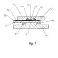
- the apparatus shown in FIG. 1 for the thermostating of a measuring cell 1 which can be used in an analyzer has at least one essentially planar measuring cell wall 2, which is provided with a thermostatable Support surface 3 of the analyzer can be brought into contact.
- the support surface 3 serves for the uniform transmission of the heating energy provided by a heating or cooling element 4 (eg Peltier element).
- the measuring cell 1 is designed in the example shown as a two-part flow cell, which flows through the sample in a flow direction normal to the plane of the drawing.
- the planar measuring cell wall 2 is designed as a housing lower part, consists of a highly thermally conductive material and limited with a thermally insulating housing upper part 5 - with the interposition of sealing elements 6 - the measuring channel 7.
- the two housing parts 2, 5 are connected by means of the locking elements 8, 9.
- At least one sensor element 10, for example an electrochemical sensor, is arranged in the measuring channel 7.
- the planar measuring cell wall 2 consists of a metal or a metal alloy, so that a good heat transfer to the sensor elements 10 and the sample in the measuring channel 7 is ensured.
- these and their interconnects 12 are arranged on the measuring cell wall 2 for the derivation of the sensor signals with the interposition of an intermediate layer 13 which effects an electrical insulation.
- the planar measuring cell wall 2 consists of plastic or an electrically non-conductive inorganic material, such as e.g. Ceramic, so that here no intermediate layer 13, which causes an electrical insulation, is necessary.
- a thermally conductive, elastic or plastic layer 11 is provided which adheres to one of the two adjacent surfaces 2 or 3 and when replacing the measuring cell of the other of the two adjacent surfaces 3 and 2 respectively residue-free removable.
- the layer 11 is fixed to the planar lower housing part 2, so that it is renewed each time the measuring cell 1.
- the thermally conductive, elastic or plastic layer 11 is preferably made of a thermally conductive silicone material and may be cured, for example, in situ on the planar measuring cell wall 2 or the thermostatable support surface 3 of the analyzer.
- the application of the thermally conductive, elastic or plastic layer 11 can also be done by screen printing, stencil printing or similar methods.
- FIG. 3 combines the advantages of the variants shown in FIGS. 1 and 2.
- the planar measuring cell wall 2 here consists of metal or a metal alloy, to further improve the heat transfer, a thermally conductive, elastic or plastic layer 11 between the support surface 3 of the analyzer and the measuring cell wall 2 is provided.
- FIG. 6 shows a longitudinal section of a measuring cell 1 according to this embodiment in the region of the sensor elements, which is located in a section of the sensor Measuring channel 7 has two sensor elements 10 arranged one behind the other.
- the sensor elements 10 or their interconnects 12 (which continue in the case shown here perpendicular to the sectional plane) are electrically insulated from the measuring cell wall 2 made of metal or a metal alloy by the intermediate layer 13, which causes an electrical insulation.
- the upper housing part can be designed as a planar, highly thermally conductive measuring cell wall 5 and with the interposition of a thermally conductive elastic or plastic layer 11 with a thermostated support surface 3 of the analyzer in contact, so that the thermostating of the measuring cell 1 takes place either only via the measuring cell wall 5 of the upper housing part or over both measuring cell walls 2 and 5, which - as shown in Fig. 4 - each rest with the interposition of a thermally conductive, elastic or plastic layer 11 on a thermostated support surface 3 of the analyzer
- the planar measuring cell wall 2 facing the thermostatted support of the analyzer or the housing lower part consists of metal or a metal alloy, so that a thin intermediate layer 13, which effects an electrical insulation, to the sensor element 10 and its signal output 12 is necessary. This allows a direct and rapid temperature transfer to those areas that are essential for the sensor reactions.
- Fig. 5 shows the embodiment of FIG. 4 in an exploded view with the preferably on the measuring cell walls 2 and 5 adherent thermally conductive, elastic or plastic layers 11, which are removable without residue from the support surfaces 3 of the analyzer.
- the lower housing part or the measuring cell wall 2 is laminated or coated, preferably by screen printing or stencil printing, on one side with a thermally conductive silicone (eg Thermally Conductive RTV Silicone R-2930 from NuSil Technology CA 93013 USA or ELASTOSIL® RT 675 from Wacker Silicones Germany) provided with a suitable geometry and electrically insulated on the other side if necessary.
- a thermally conductive silicone eg Thermally Conductive RTV Silicone R-2930 from NuSil Technology CA 93013 USA or ELASTOSIL® RT 675 from Wacker Silicones Germany
- the thermally conductive, elastic or plastic layer 11 may be applied substantially over the entire area (area a) or provided with a suitable geometry, in particular at its free surface a structure, for example in the form of strips 14 (area b) or nubs 15 (area c), have.
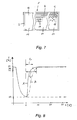
- the setting time t (in s) of a measuring cell is shown, which is to be thermostated to a predeterminable temperature T (in ° C).
- T in ° C
- a small foreign body in the special case a hair
- the measuring curve B a setting time t 2 , up to which 95%. the target temperature can be achieved.
- the response time is reduced substantially to the value t 1 .
Landscapes
- Health & Medical Sciences (AREA)
- Life Sciences & Earth Sciences (AREA)
- Chemical & Material Sciences (AREA)
- Engineering & Computer Science (AREA)
- Physics & Mathematics (AREA)
- Biomedical Technology (AREA)
- Pathology (AREA)
- Hematology (AREA)
- Biochemistry (AREA)
- General Health & Medical Sciences (AREA)
- General Physics & Mathematics (AREA)
- Immunology (AREA)
- Molecular Biology (AREA)
- Analytical Chemistry (AREA)
- Chemical Kinetics & Catalysis (AREA)
- Ecology (AREA)
- Electrochemistry (AREA)
- Biophysics (AREA)
- Urology & Nephrology (AREA)
- Food Science & Technology (AREA)
- Medicinal Chemistry (AREA)
- Optical Measuring Cells (AREA)
- Investigating Or Analysing Materials By Optical Means (AREA)
- Automatic Analysis And Handling Materials Therefor (AREA)
Abstract
Description
Die Erfindung betrifft eine Vorrichtung zur Thermostatisierung einer Messzelle in einem Analysator, zumindest bestehend aus der Messzelle mit einem Messkanal, wobei im Messkanal zumindest ein Sensorelement angeordnet ist, und dem Analysator, welcher eine thermostatisierbare Auflagefläche aufweist. Die Messzelle ist in den Analysator austauschbar einsetzbar und zumindest in einem Kontaktbereich mit der thermostatisierbaren Auflagefläche in Kontakt bringbar, wobei die Messzelle eine zumindest in diesem Kontaktbereich im Wesentlichen planare Messzellenwand aufweist. Weiters betrifft dir Erfindung eine Messzelle, welche in einen Analysator austauschbar einsetzbar ist.The invention relates to a device for thermostating a measuring cell in an analyzer, at least consisting of the measuring cell with a measuring channel, wherein in the measuring channel at least one sensor element is arranged, and the analyzer, which has a thermostatable bearing surface. The measuring cell can be used interchangeably in the analyzer and can be brought into contact with the thermostatted bearing surface at least in a contact region, wherein the measuring cell has a measuring cell wall which is essentially planar at least in this contact region. Furthermore, the invention relates to a measuring cell, which can be used interchangeably in an analyzer.
Es ist bekannt, dass viele Einrichtungen und Vorrichtungen, die Sensoren aufweisen, temperaturabhängige Signaleigenschaften zeigen. Diese Temperaturabhängigkeit ist je nach Sensortyp durch die Beeinflussung chemischer Prozesse, deren Gleichgewichtslage und/oder deren Kinetik bedingt, oder wird insbesondere bei elektrochemischen Sensoren durch Änderung physikalischer Eigenschaften, wie z.B. der elektrischen Leitfähigkeit, hervorgerufen.It is well known that many devices and devices that include sensors exhibit temperature-dependent signal characteristics. Depending on the type of sensor, this temperature dependence is dependent on the influence of chemical processes, their equilibrium position and / or their kinetics, or, in particular in the case of electrochemical sensors, by changing physical properties, e.g. the electrical conductivity, caused.
Derartige Sensoren werden häufig in medizinischen Analysensystemen zur Bestimmung von Gaspartialdrucken von Blut, des pH-Wertes oder der Ionen- und Metabolitkonzentrationen von Körperflüssigkeiten eingesetzt. Insbesondere werden solche Sensoren in Blutgasanalysatoren eingesetzt, welche in der Diagnostik eine große Rolle spielen.Such sensors are often used in medical analysis systems for the determination of gas partial pressures of blood, the pH or the ion and metabolite concentrations of body fluids. In particular, such sensors are used in blood gas analyzers, which play a major role in diagnostics.
Während nun die Temperaturkoeffizienten der Sensoren relativ leicht durch entsprechende Kalibrationsmessungen ermittelt werden könnten, besteht ein Problem darin, dass beispielsweise bei der Bestimmung von Blutgasen und pH die Messgrößen (pO2, pCO2, pH) temperaturabhängig sind, und die für die Umrechnung erforderlichen Temperaturkoeffizienten der Probe nicht hinreichend genau bekannt sind. Eine Umrechnung der für eine Blutprobe, beispielsweise bei Raumtemperatur, gewonnenen Messwerte auf die bei Körpertemperatur (37°C) vorliegenden Messwerte ist daher ungenau.While the temperature coefficients of the sensors could be determined relatively easily by corresponding calibration measurements, there is a problem that, for example, in the determination of blood gases and pH, the measured variables (pO 2 , pCO 2 , pH) are temperature-dependent, and the temperature coefficients required for the conversion the sample is not known with sufficient accuracy. A conversion of the measured values obtained for a blood sample, for example at room temperature, to the measured values present at body temperature (37 ° C.) is therefore inaccurate.
Um die oben genannten Temperaturabhängigkeiten zu vermeiden, ist es bekannt, Messzellen mit Sensoren unter kontrollierten Temperaturverhältnissen - in Thermostaten - einzusetzen. Wenn Messzellen nach einer gewissen Einsatzzeit ausgetauscht werden sollen, ist für eine leichte Trennbarkeit zwischen der Messzelle einerseits und dem Thermostaten, der ein fester Bestandteil des Analysators ist, andererseits zu sorgen.In order to avoid the above-mentioned temperature dependencies, it is known to use measuring cells with sensors under controlled temperature conditions - in thermostats. If measuring cells after a certain period of use be replaced, is on the other hand to ensure easy separability between the measuring cell on the one hand and the thermostat, which is an integral part of the analyzer.
Im Allgemeinen werden die Messzellen in einer thermostatisierten Kammer des Analysators, welche auf konstanter Temperatur gehalten wird und zumeist aus einer Metalllegierung oder einem keramischen Werkstoff gefertigt ist, betrieben.In general, the measuring cells are operated in a thermostated chamber of the analyzer, which is kept at a constant temperature and is usually made of a metal alloy or a ceramic material.
Besonders bei gelösten Gasen spielt die Temperatur der Probe zum Zeitpunkt der Messung eine wesentliche Rolle. Die Löslichkeit von Gasen in z.B. wässrigen Medien nimmt mit steigender Temperatur ab, sodass das gelöste Gas die Tendenz zeigt, aus der Lösung zu entweichen. Hierdurch wird ein höherer Wert gemessen. Umgekehrt wird bei einer niedrigeren Messtemperatur ein tieferer Wert ermittelt.Especially with dissolved gases, the temperature of the sample at the time of measurement plays an essential role. The solubility of gases in e.g. aqueous media decreases with increasing temperature, so that the dissolved gas tends to escape from the solution. This measures a higher value. Conversely, a lower value is determined at a lower measurement temperature.
In der Medizin spielt die Analyse der Blutgasparameter eine wichtige Rolle, insbesondere im Rahmen einer Notfalluntersuchung. Unter dem Sammelbegriff Blutgasparameter versteht man die Werte für den Partialdruck des Sauerstoffs, des Kohlendioxides (der in einer physiologischen Probe gelösten Gase) und den pH-Wert der physiologischen Probe bzw. einer wässrigen Kontrolllösung.In medicine, the analysis of blood gas parameters plays an important role, especially in the context of an emergency examination. The collective term blood gas parameters refers to the values for the partial pressure of the oxygen, the carbon dioxide (the gases dissolved in a physiological sample) and the pH of the physiological sample or an aqueous control solution.
Um die Situation im Körper des Patienten bestmöglich zu erfassen, wird hierbei bei einer Probentemperatur von 37°C gemessen. Auch wenn zwischen der Probennahme und dem Messzeitpunkt nur wenig Zeit vergeht, ist die Blutprobe deutlich abgekühlt und muss im Analysator sehr rasch wieder auf Körpertemperatur gebracht werden.In order to capture the situation in the body of the patient as best as possible, it is measured at a sample temperature of 37 ° C. Even if only little time passes between the sampling and the time of measurement, the blood sample has cooled significantly and must be brought back to body temperature very quickly in the analyzer.
Die in der Messzelle eingesetzten Sensoren werden konstant auf der Messtemperatur gehalten, in diesem Fall auf 37°C. Dies ist notwendig, da der massive Heizblock (großes Gewicht) im Wärmeverlauf sehr träge reagiert und die Messzelle durch ihren Aufbau aus polymeren Werkstoffen (siehe beispielsweise EP 1 087 224 A2), die bekanntermaßen schlechte bis sehr schlechte Wärmeleiter sind, ebenfalls sehr träge bei einem Temperaturwechsel reagieren. Die thermostatisierten Gehäuseteile bestehen beispielsweise aus Polykarbonat, wobei Wandstärken von bis zu 5 mm vorgesehen sind, die ebenfalls den Wärmeübergangswiderstand vergrößern.The sensors used in the measuring cell are kept constant at the measuring temperature, in this case at 37 ° C. This is necessary because the massive heating block (large weight) reacts very sluggishly in the heat and the measuring cell by its construction of polymeric materials (see, for example, EP 1 087 224 A2), which are known to be poor to very poor heat conductors, also very sluggish at a Temperature change react. The thermostated housing parts consist for example of polycarbonate, with wall thicknesses of up to 5 mm are provided, which also increase the heat transfer resistance.
Auch wenn die Messzelle an eine oder mehrere thermostatisierte Oberflächen des Analysators gedrückt wird, ist die Berührung der thermostatisierten Oberfläche nur an wenigen Punkten und auf unreproduzierbare Art und Weise gegeben. Aus der EP 1 367 392 A1 ist in diesem Zusammenhang ein Analysengerät mit einer thermostatisierbaren Messzelle bekannt, die nicht näher beschriebene elektrochemische Elektroden aufweist. Die Messzelle wird mit Peltier-Elementen thermostatisiert, wobei zwischen den Peltier-Elementen und der Messzellenwand ein flaches, thermisch leitendes Verteilerelement angeordnet ist. Die so gewählte Thermostatisierung kommt daher aufgrund der unvermeidbaren Luftspalte einem Luftbad gleich, sodass der Wärmeübergang in der Hauptsache durch die Dicke des schlecht wärmeleitenden polymeren Werkstoffes um den elektrochemischen Sensor und der verbleibenden Luftspalte zur thermostatisierten Oberfläche begrenzt wird.Even if the measuring cell is pressed against one or more thermostated surfaces of the analyzer, the contact of the thermostated surface is given only in a few points and in an irreproducible manner. From EP 1 367 392 A1 an analyzer with a thermostatable measuring cell is known in this connection, which has electrochemical electrodes not described in more detail. The measuring cell is thermostated with Peltier elements, whereby between the Peltier elements and the measuring cell wall flat, thermally conductive distribution element is arranged. Due to the unavoidable air gaps, the selected thermostating therefore equals an air bath, so that the heat transfer is mainly limited by the thickness of the poorly thermally conductive polymer material around the electrochemical sensor and the remaining air gaps to the thermostated surface.
Die Folge einer solchen Anordnung ist eine verzögerte Temperaturannahme des Sensors und der Probe. Damit ist die Messbereitschaft bei der jeweiligen Solltemperatur verlangsamt. Um in der Praxis diese Phase möglichst kurz zu halten, wird die Probe in einer Vorwärmstrecke, die der Messzelle vorgeschaltet ist, auf etwa die Solltemperatur gewärmt. Somit wird die Temperaturannahme der Sensoren bzw. der Proben am Messort wesentlich erleichtert und die erforderliche Solltemperatur rascher erreicht.The consequence of such an arrangement is a delayed temperature acceptance of the sensor and the sample. Thus, the measuring readiness is slowed down at the respective target temperature. In order to keep this phase as short as possible in practice, the sample is warmed in a preheating, which is connected upstream of the measuring cell to about the target temperature. Thus, the temperature acceptance of the sensors or the samples at the measurement location is much easier and reaches the required setpoint temperature faster.
Manche Sensoren beinhalten Bestandteile, welche jedoch bei der erforderlichen Betriebstemperatur eine eingeschränkte Lebensdauer aufweisen, wie z.B. Enzyme, die die erforderlichen Sensorreaktionen am Messort ermöglichen. Wenn diese Enzyme durch längere Temperatureinwirkung teilweise oder gänzlich zerstört sind, das heißt, in ihrer Aktivität vermindert sind oder sogar inaktiviert wurden, kann der Sensor nicht mehr verwendet werden. Die Verwendungsdauer dieser enzymhaltigen Sensoren ist dadurch üblicherweise verkürzt.Some sensors include components which, however, have a limited life at the required operating temperature, e.g. Enzymes that enable the required sensor reactions at the measurement site. If these enzymes are partially or completely destroyed by prolonged exposure to heat, that is, have been reduced in activity or even inactivated, the sensor can no longer be used. The duration of use of these enzyme-containing sensors is thereby usually shortened.
In diesem Zusammenhang ist aus der US 5,046,496 A eine Sensoreinrichtung zur Messung der Blutgasparameter pH, pCO2 und pO2 bekannt geworden, bei welcher die einzelnen Elektroden mit Hilfe einer Dickfilmtechnik auf ein rechteckiges Trägerplättchen aus nicht leitender Keramik aufgetragen sind. Das Trägerplättchen mit den Messelektroden wird in das Gehäuse einer Durchflusszelle eingeklebt. Auf dem Trägerplättchen befinden sich weiters ein Temperatursensor und ein Heizelement, um die für die Messung notwendige Temperatur bereitzustellen und zu regeln. Nachteilig dabei ist der zusätzliche Aufwand, der mit der Integration eines Heizelementes sowie eines Temperaturmesselementes direkt in die Messzelle verbunden ist.In this context, US Pat. No. 5,046,496 A has disclosed a sensor device for measuring the blood gas parameters pH, pCO 2 and pO 2 , in which the individual electrodes are applied to a rectangular carrier plate made of non-conductive ceramic by means of a thick-film technique. The carrier plate with the measuring electrodes is glued into the housing of a flow cell. On the carrier plate are also a temperature sensor and a heating element to provide the necessary temperature for the measurement and to regulate. The disadvantage here is the additional expense that is associated with the integration of a heating element and a temperature measuring element directly into the measuring cell.
Aus der US 2003/0220583 A1 ist ein portables Diagnosesystem bekannt, bei welchem das Heizelement ebenfalls direkt in den Sensorchip mit den einzelnen Elektroden integriert ist, wobei der Sensorchip zur Temperaturmessung von einem IR-Sensor berührungslos abgetastet wird.From US 2003/0220583 A1, a portable diagnostic system is known in which the heating element is likewise integrated directly into the sensor chip with the individual electrodes, wherein the sensor chip for temperature measurement is scanned by an IR sensor without contact.
Wird bei austauschbaren Sensoren das Heizelement nicht im jeweiligen Sensorgehäuse integriert, sondern zentral im Analysator angebracht, so ist eine deutlich kostengünstigere und einfachere Fertigung der Sensoren/Messzellen möglich, da zu deren Fertigung weniger Bauteile bzw. Prozessschritte benötigt werden.If, in the case of exchangeable sensors, the heating element is not integrated in the respective sensor housing, but is mounted centrally in the analyzer, a significantly less expensive and simpler manufacture of the sensors / measuring cells is possible because fewer components or process steps are required for their production.
Schließlich ist aus der US 2003/0057108 A1 ein Verfahren zu schnellen Hydratisierung und Erwärmung von chemischen, elektrochemischen und biochemischen Sensoren bekannt. Die Sensorkassette besteht aus einem Unterteil aus Kunststoff, in welchem die Sensoren angeordnet sind und einer Abdeckplatte aus Metall, welche auch zur Übertragung von Wärme in die Sensorkassette verwendet werden kann. Zu diesem Zweck ist die Abdeckplatte mit entsprechenden Heiz-oder Kühlelementen, beispielsweise einem Peltier-Element, kontaktiert.Finally, US 2003/0057108 A1 discloses a process for rapid hydration and heating of chemical, electrochemical and biochemical sensors. The sensor cassette consists of a lower part made of plastic, in which the sensors are arranged and a cover plate made of metal, which can also be used to transfer heat into the sensor cassette. For this purpose, the cover plate with corresponding heating or cooling elements, such as a Peltier element, contacted.
Aufgabe der Erfindung ist es, ausgehend vom dargelegten Stand der Technik eine Vorrichtung zur Thermostatisierung einer in einen Analysator einsetzbaren Messzelle vorzuschlagen, welche möglichst unter Verzicht auf eine Vorwärmstrecke für eine rasche, reproduzierbare Thermostatisierung der in der Messzelle vorliegenden Sensoren, der Kalibriermedien, der Kontrollmedien und der Probe geeignet ist, wobei ein problemloser Wechsel der Messzelle bei einer Fehlfunktion oder nach Ablauf der Einsatzzeit gewährleistet sein soll.The object of the invention is, starting from the above prior art, to propose a device for thermostating an insertable into an analyzer measuring cell, which preferably waiving a Vorwärmstrecke for rapid, reproducible thermostats of the present in the measuring cell sensors, the calibration, the control media and the sample is suitable, with a problem-free change of the measuring cell should be ensured in case of malfunction or after the end of the period of use.
Diese Aufgabe wird erfindungsgemäß dadurch gelöst, dass zur Verbesserung des Wärmeüberganges auf die Messzelle eine wärmeleitfähige, elastische oder plastische Schicht vorgesehen ist, welche zumindest im Kontaktbereich an zumindest einer Messzellenwand oder der thermostatisierbaren Auflagefläche des Analysators haftet und beim Austausch der Messzelle von der gegenüberliegenden thermostatisierbaren Auflagefläche oder Messzellenwand weitgehend rückstandsfrei entfernbar ist und/oder dass die Messzellenwand, an deren dem Messkanal zugewandten Innenseite das zumindest eine Sensorelement angeordnet ist, zumindest im Kontaktbereich mit der thermostatisierbaren Auflagefläche des Analysators aus einem wärmeleitfähigen Metall oder einer Metalllegierung besteht.This object is achieved in that for improving the heat transfer to the measuring cell, a thermally conductive, elastic or plastic layer is provided which adheres at least in the contact area on at least one measuring cell wall or the thermostatable support surface of the analyzer and the exchange of the measuring cell from the opposite thermostatable support surface or measuring cell wall is largely residue-free removable and / or that the measuring cell wall, at the inner side facing the measuring channel the at least one sensor element is arranged, at least in the contact region with the thermostatable support surface of the analyzer of a thermally conductive metal or a metal alloy.
Durch diese erfindungsgemäßen Maßnahmen (wärmeleitfähige Schicht bzw. metallische Messzellenwand), welche auch kombiniert werden können, wird der Wärmedurchgangswiderstand von der Wärmequelle, der thermostatisierten Auflagefläche des Analysators, bis zur Sensor- bzw. Probenebene wesentlich minimiert. Weiters kann eine schadhafte Messzelle oder eine Messzelle am Ende deren Standzeit problemlos ausgetauscht und einfach durch eine neue Messzelle ersetzt werden, ohne die thermischen Gegebenheiten zu ändern.By these measures according to the invention (thermally conductive layer or metallic measuring cell wall), which can also be combined, the heat transfer resistance of the heat source, the thermostated bearing surface of the analyzer, to the sensor or sample level is substantially minimized. Furthermore, a defective measuring cell or a measuring cell can easily be replaced at the end of their service life and simply replaced by a new measuring cell without changing the thermal conditions.
Gemäß einer Ausführungsvariante der Erfindung kann die Messzelle zwei oder mehrere planare Messzellenwände aufweisen, die jeweils unter Zwischenlage einer wärmeleitfähigen, elastischen oder plastischen Schicht, welche zumindest im Kontaktbereich an der jeweiligen Messzellenwand oder der thermostatisierbaren Auflagefläche des Analysators haftet und beim Austausch der Messzelle von der jeweiligen gegenüberliegenden thermostatisierbaren Auflagefläche oder Messzellenwand weitgehend rückstandsfrei entfernbar ist, an einer thermostatisierbaren Auflagefläche des Analysators anliegen.According to one embodiment of the invention, the measuring cell may have two or more planar measuring cell walls, each with the interposition of a thermally conductive, elastic or plastic layer, which adheres at least in the contact area to the respective measuring cell wall or the thermostated support surface of the analyzer and when replacing the measuring cell of the respective opposite thermostatable bearing surface or measuring cell wall is largely residue-free removable, abut a thermostatically supporting surface of the analyzer.
Bei einer metallischen Messzellenwand, beispielsweise aus Kupfer oder Aluminium, kann aufgrund der hohen Festigkeit metallischer Werkstoffe die Messzellenwand sehr dünn ausgeführt sein, beispielsweise in Form eines Blättchens mit einer Dicke von vorzugsweise bis zu 2000 µm, besonders bevorzugt bis zu 1000 µm. Dadurch, dass die Metallschicht sehr dünn ausgebildet wird, kann auch die Wärmekapazität minimiert werden, so dass die gewünschte Messzellentemperatur schneller erreicht wird.In a metallic measuring cell wall, for example made of copper or aluminum, due to the high strength of metallic materials, the measuring cell wall can be made very thin, for example in the form of a leaflet with a thickness of preferably up to 2000 .mu.m, more preferably up to 1000 .mu.m. The fact that the metal layer is formed very thin, the heat capacity can be minimized so that the desired Messzellentemperatur is achieved faster.
Bei Verwendung elektrochemischer Sensoren können die elektrisch leitenden Strukturen allerdings nicht direkt auf ein Metallblättchen aufgebracht werden. Zur Vermeidung von Kurzschlüssen ist daher bei einer Messzellenwand aus Metall oder einer Metalllegierung der zumindest eine elektrochemische Sensor unter Zwischenlage einer Zwischenschicht, welche eine elektrischen Isolierung bewirkt, an der dem Messkanal zugewandten Seite der planaren Messzellenwand angeordnet. Zur elektrischen Isolierung wird eine sehr dünne, vorzugsweise bis zu 100 µm dicke, besonders bevorzugt bis zu 10 µm dicke, elektrisch nicht-leitende Schicht, beispielsweise eine Kunststoffschicht, auf die Messzellenwand aus Metall oder einer Metalllegierung aufgebracht. Diese kann durch eine dünne Schicht, z.B. aus einem Polymer, gebildet werden, die durch Laminierung oder Beschichten aufgetragen wird. Beispiele zur Erzeugung elektrisch nicht-leitender Kunststoffschichten sind z.B. Kunststoff-Folien aus Polykarbonat, Polyester oder Polyvinylchlorid, die auf das Metallblättchen aufgeklebt werden oder Polykarbonat-und Polyesterlacke, die auf das Metallblättchen aufgebracht werden.When using electrochemical sensors, however, the electrically conductive structures can not be applied directly to a metal plate. In order to avoid short circuits, therefore, in the case of a measuring cell wall made of metal or a metal alloy, the at least one electrochemical sensor is arranged on the side of the planar measuring cell wall facing the measuring channel with the interposition of an intermediate layer which effects electrical insulation. For electrical insulation, a very thin, preferably up to 100 microns thick, more preferably up to 10 microns thick, electrically non-conductive layer, such as a plastic layer, applied to the measuring cell wall of metal or a metal alloy. This can be achieved by a thin layer, e.g. from a polymer which is applied by lamination or coating. Examples of producing electrically non-conductive plastic layers are e.g. Plastic films of polycarbonate, polyester or polyvinyl chloride adhered to the metal plate or polycarbonate and polyester coatings applied to the metal plate.
Auch bei Verwendung von Sensortypen, welche nicht auf elektrochemischen Technologien beruhen bzw. keine elektrischen Ableitungen benötigen, weist die erfindungsgemäße Ausführung der Messzellenwand, an deren dem Messkanal zugewandten Innenseite das zumindest eine Sensorelement angeordnet ist, Vorteile auf, wenn diese zumindest im Kontaktbereich mit der thermostatisierbaren Auflagefläche des Analysators aus einem wärmeleitfähigen Metall oder einer Metalllegierung bestehen. Solche Sensortypen sind beispielsweise Sensoren, welche auf optischen Technologien basieren oder auf der Bestimmung intrinsischer Eigenschaften der Probenflüssigkeit, beispielsweise deren elektrischer Leitfähigkeit, beruhen, da auch solche Sensoren unter möglichst definierten Temperaturbedingungen betrieben werden müssen, um zu möglichst exakten und reproduzierbaren Analytbestimmungen zu gelangen.Even when using sensor types which are not based on electrochemical technologies or do not require electrical discharges, the inventive design of the measuring cell wall, at whose inner side facing the measuring channel the at least one sensor element is arranged, has advantages, if these at least in the contact area with the thermostatable Support surface of the analyzer made of a thermally conductive metal or a metal alloy. Such sensor types are, for example, sensors which are based on optical technologies or based on the determination of intrinsic properties of the sample liquid, for example their electrical conductivity, since such sensors must also be operated under defined temperature conditions in order to obtain the most accurate and reproducible analyte determinations.
Da es für eine rasche und reproduzierbare Thermostatisierung wesentlich ist, neben den in die Messzelle eingebrachten Medien, wie Kalibriermedien, Kontrollmedien oder Probenflüssigkeiten, auch die in der Messzelle vorliegenden Sensoren schnellstmöglich auf die erforderliche Betriebstemperatur zu bringen, ist die erfindungsgemäße Ausführung vorteilhaft, da hier der Wärmetransfer zu den Sensoren besonders rasch und reproduzierbar erfolgen kann. Insbesondere ist diese erfindungsgemäße Ausführungsform besonders vorteilhaft gegenüber Ausführungsformen, bei welchen eine Metallschicht zum Wärmetransfer an der den Sensoren abgewandten Messzellenwand angebracht ist, da dort die Thermostatisierung der Sensoren durch die beschränkte Wärmeleitfähigkeit des sich zwischen Messzellenwand und Sensoren befindlichen Mediums langsamer erfolgt. Durch die Tatsache, dass unterschiedliche in der Messzelle vorliegende Medien, beispielsweise unterschiedliche Kalibriermedien, Kontrollmedien oder Probenflüssigkeiten, unterschiedliche Wärmeleitfähigkeiten aufweisen, erfolgt der Wärmetransfer bei solchen Anordnungen nicht exakt reproduzierbar. Dies ist insbesondere bei gasförmigen Kalibriermedien der Fall, wie sie beispielsweise bei Sensoren zur Bestimmung gasförmiger Analyten wie Sauerstoff eingesetzt werden können. Im Gegensatz dazu erfolgt entsprechend der erfindungsgemäßen Lösung der Wärmetransfer zwischen der thermostatisierbaren Auflagefläche des Analysators und den Sensoren in vorteilhafter Weise entlang definierter Schichten, deren Wärmeleitfähigkeiten bekannt sind.As it is essential for a rapid and reproducible thermostating, in addition to the media introduced into the measuring cell, such as calibration media, control media or sample liquids, the sensors present in the measuring cell as quickly as possible to bring to the required operating temperature, the embodiment of the invention is advantageous, since the heat transfer to the sensors can be done very quickly and reproducibly here. In particular, this embodiment according to the invention is particularly advantageous over embodiments in which a metal layer for heat transfer is attached to the measuring cell wall facing away from the sensors, since there the thermostatting of the sensors takes place more slowly due to the limited thermal conductivity of the medium located between measuring cell wall and sensors. Due to the fact that different media present in the measuring cell, for example different calibration media, control media or sample liquids, have different thermal conductivities, the heat transfer in such arrangements is not exactly reproducible. This is the case in particular with gaseous calibration media, as can be used, for example, in sensors for the determination of gaseous analytes such as oxygen. In contrast, according to the solution according to the invention, the heat transfer between the thermostatable support surface of the analyzer and the sensors advantageously takes place along defined layers whose thermal conductivities are known.
Messzellenwände, an deren dem Messkanal zugewandten Innenseite das zumindest eine Sensorelement angeordnet ist und welche zumindest im Kontaktbereich mit der thermostatisierbaren Auflagefläche des Analysators aus einem wärmeleitfähigen Metall oder einer Metalllegierung bestehen, müssen im Sinne der vorliegenden Anmeldung nicht unbedingt als durchgehende Metallschichten ausgebildet sein. So sind im Rahmen der vorliegenden Erfindung auch Ausführungsformen umfasst, bei welchen die Metallschicht Aussparungen in bestimmten Teilbereichen, beispielsweise in Form von Löchern oder Gitterstrukturen, aufweist. Solche Ausführungsformen sind beispielsweise dann besonders vorteilhaft, wenn optische Sensortechnologien eingesetzt werden, da durch solche räumlich begrenzten Aussparungen in der Metallschicht ein Einstrahlen von Licht zu den Sensoren hin bzw. ein Auslesen des von den Sensoren emittierten Lichts ermöglicht wird, ohne den erfindungsgemäßen Wärmetransfer zu den Sensoren und zum Messkanal wesentlich zu verschlechtern, insbesondere wenn die Aussparungen möglichst geringe Flächen der Metallschicht einnehmen. Solche optischen Sensortechnologien sind beispielsweise in "Fluorescent optical sensors for critical care analysis" J.K. Tusa, M.J.P. Leiner; Ann Biol Clin 2003, 61:183-191 beschrieben. Auch bei elektrochemischen Sensortechnologien können solche Metallschichten mit Aussparungen in bestimmten Ausführungsformen vorteilhaft eingesetzt werden, da durch solche Aussparungen in der Metallschicht ein Durchkontaktieren der Sensoren auch durch die erfindungsgemäße Metallschicht möglich ist. Hierzu ist es aber weiterhin notwendig, eine entsprechende elektrische Isolierung der Bauteile zu gewährleisten, beispielsweise durch einen Luftspalt zwischen Metallschicht und elektrischer Ableitung des Sensors oder durch das Aufbringen einer isolierenden Schicht auf die Oberfläche der Metallschicht im Bereich der Aussparungen oder auf die elektrische Ableitung des Sensors.Measuring cell walls, at the inner side of the measuring channel facing the at least one sensor element is arranged and which consist at least in the contact area with the thermostatable support surface of the analyzer of a thermally conductive metal or a metal alloy, need not necessarily be formed as continuous metal layers within the meaning of the present application. In the context of the present invention, embodiments are also encompassed in which the metal layer has recesses in specific subregions, for example in the form of holes or lattice structures. Such embodiments are particularly advantageous, for example, when optical sensor technologies are used, since such spatially limited recesses in the metal layer allow light to be transmitted to the sensors or read out the light emitted by the sensors without the heat transfer according to the invention Sensors and the measuring channel to deteriorate significantly, especially when the recesses occupy the smallest possible areas of the metal layer. Such optical sensor technologies are described, for example, in "Fluorescent optical sensors for critical care analysis" by JK Tusa, MJP Leiner; Ann Biol Clin 2003, 61: 183-191. Even in the case of electrochemical sensor technologies, such metal layers with recesses can advantageously be used in certain embodiments, because through such recesses in the metal layer, a through-contacting of the sensors is also possible through the metal layer according to the invention. For this purpose, it is still necessary, a corresponding electrical insulation to ensure the components, for example, by an air gap between the metal layer and electrical discharge of the sensor or by applying an insulating layer on the surface of the metal layer in the region of the recesses or on the electrical discharge of the sensor.
Die Zwischenlage einer Zwischenschicht zwischen einer Messzellenwand aus Metall oder einer Metalllegierung und dem Messkanal bzw. den dem Messkanal zugewandeten Sensoren kann bei allen Sensortypen, nicht nur bei elektrochemischen Sensoren, vorteilhaft sein. Eine solche Zwischenschicht kann beispielsweise zu einer vorteilhaften Beeinflussung der Oberflächeneigenschaften des Messkanals, beispielsweise einer verbesserten Hydrophilie dessen Oberflächen, zur Erzielung verbesserter Oberflächeneigenschaften, insbesondere Haftungseigenschaften, für den Aufbau weiterer Schichten, zur Verbesserung des Korrosionsschutzes der darunter liegenden Metallschicht oder zur Vermeidung unerwünschter Reaktionen zwischen Metallschicht und der im Messkanal befindlichen Flüssigkeiten dienen.The intermediate layer of an intermediate layer between a measuring cell wall made of metal or a metal alloy and the measuring channel or the sensors facing the measuring channel may be advantageous in all sensor types, not only in electrochemical sensors. Such an intermediate layer can, for example, advantageously influence the surface properties of the measuring channel, for example an improved hydrophilicity of the surfaces, to achieve improved surface properties, in particular adhesion properties, to build up further layers, to improve the corrosion protection of the underlying metal layer or to avoid undesired reactions between the metal layer and the liquids in the measuring channel.
In einer weiteren bevorzugten Ausführungsform ist die erfindungsgemäße Vorrichtung zur Thermostatisierung einer Messzelle in einem Analysator bzw. die Messzelle selbst derartig ausgebildet, dass das zumindest eine Sensorelement der Messzelle als optisches Sensorelement ausgebildet ist und unter Zwischenlage einer Zwischenschicht, welche optisch transparent ist, an der Messzellenwand, welche beispielsweise aus einem Metall oder einer Metalllegierung besteht, angeordnet ist. Beim Einsatz optischer Sensortechnologien kann eine Zwischenschicht zwischen Sensoren und der benachbarten, dem Wärmetransfer dienenden Metallschicht auch vorteilhafterweise derartig ausgebildet sein, dass sie optisch transparent ist. Ferner kann sie so ausgebildet sein, dass sie Lichtleiterfunktionen übernehmen kann. Eine solche Zwischenschicht kann insbesondere dazu eingesetzt werden, Anregungslicht zu den Sensoren bzw. von den Sensoren emittiertes Licht zu geeigneten Detektoren hinzuleiten. Solche Ausführungsformen sind insbesondere für optische Verfahren und Anordnungen, bei welchen das Anregungslicht bzw. das emittierte Licht seitlich ein- bzw. ausgestrahlt werden soll und wie sie beispielsweise in der EP 0 793 090 B1 beschrieben sind, vorteilhaft. Auch Kombinationen einer solchen lichtleitenden Zwischenschicht mit einer Metallschicht, welche im Bereich der Sensoren Aussparungen aufweist, sind in vorteilhafter Weise möglich, beispielsweise bei einer Detektion der von den Sensoren emittierten Strahlung senkrecht zur Einstrahlungsrichtung des Anregungslichtes.In a further preferred embodiment, the device according to the invention for thermostating a measuring cell in an analyzer or the measuring cell itself is designed such that the at least one sensor element of the measuring cell is designed as an optical sensor element and with the interposition of an intermediate layer, which is optically transparent, on the measuring cell wall , which consists for example of a metal or a metal alloy, is arranged. When using optical sensor technologies, an intermediate layer between sensors and the adjacent, the heat transfer serving metal layer may also be advantageously designed such that it is optically transparent. Furthermore, it can be designed so that it can take over optical fiber functions. Such an intermediate layer can in particular be used to direct excitation light to the sensors or light emitted by the sensors to suitable detectors. Such embodiments are particularly advantageous for optical methods and arrangements in which the excitation light or the emitted light is to be emitted or emitted laterally and as described, for example, in EP 0 793 090 B1. Combinations of such a light-conducting intermediate layer with a metal layer, which has recesses in the region of the sensors, are also possible in an advantageous manner, for example when detecting the radiation emitted by the sensors perpendicular to the direction of irradiation of the excitation light.
Gemäß einer vorteilhaften Ausführungsvariante der Erfindung weist die wärmeleitfähige, elastische oder plastische Schicht zumindest an deren freien Oberfläche eine Struktur, beispielsweise in Form von Streifen, Noppen oder dgl., auf.According to an advantageous embodiment of the invention, the thermally conductive, elastic or plastic layer at least on the free surface of a structure, for example in the form of strips, knobs or the like., On.
Zur Verbesserung der Wärmeleitung kann die wärmeleitfähige, elastische oder plastische Schicht Partikel aus einem gut wärmeleitenden Material, vorzugsweise keramische Partikel, aufweisen.To improve the heat conduction, the thermally conductive, elastic or plastic layer may comprise particles of a good heat-conducting material, preferably ceramic particles.
Weiters kann die Vorrichtung, bestehend aus Messzelle und Heiz- bzw. Kühlelement des Analysators bzw. dessen thermostatisierbarer Auflagefläche miniaturisiert werden, sodass bei einer geringeren Masse bzw. einer geringeren Baugröße die Solltemperatur rascher und ohne Verwendung einer Vorwärmstrecke erreicht werden kann.Furthermore, the device, consisting of measuring cell and heating or cooling element of the analyzer or its thermostatisierbarer support surface can be miniaturized, so that at a lower mass or a smaller size, the target temperature can be achieved more quickly and without the use of a preheating.
Um den Wärmeübergang von der Wärmequelle zur Probe selbst bei Verwendung einer wärmeleitfähigen, elastischen oder plastischen Schicht weiter zu verbessern, kann die im Wesentlichen planare Messzellenwand aus einem gut wärmeleitenden Material, vorzugsweise aus Keramik, aus einem Metall oder einer Metalllegierung, ausgeführt sein. Als Materialien eignen sich z.B. Keramiken aus diversen Oxyden und Nitriden, wie z.B. Aluminiumoxyd, Aluminiumnitrid, Zirkoniumoxyd, Zirkoniumnitrid, Boroxyd oder Bornitrid, etc. oder Metalle wie Kupfer oder Aluminium, etc.In order to further improve the heat transfer from the heat source to the sample even when using a thermally conductive, elastic or plastic layer, the substantially planar measuring cell wall can be made of a good heat-conducting material, preferably of ceramic, of a metal or a metal alloy. Suitable materials are e.g. Ceramics of various oxides and nitrides, e.g. Alumina, aluminum nitride, zirconia, zirconium nitride, boron oxide or boron nitride, etc., or metals such as copper or aluminum, etc.
Gemäß einer vorteilhaften Ausführungsvariante kann die Messzelle zweiteilig ausgebildet sein und bei einseitiger Thermostatisierung aus einem durch die zumindest im Kontaktbereich zur thermostatisierbaren Auflagefläche planare Messzellenwand gebildeten Gehäuseunterteil aus einem gut wärmeleitenden Material und einem thermisch isolierenden Gehäuseoberteil bestehen, welches unter Zwischenlage von Dichtelementen den Messkanal begrenzt.According to an advantageous embodiment, the measuring cell may be formed in two parts and in one-sided thermostatting from a formed by the at least in the contact area for thermostatically adjustable support surface measuring cell bottom housing made of a good heat conducting material and a thermally insulating housing upper part, which limits the measuring channel with the interposition of sealing elements.
Die erfindungsgemäße Vorrichtung weist eine Reihe von Vorteilen auf:
- Der Wärmeübergang, der damit erzielbar ist, ermöglicht bei geeigneter Sensorkonstruktion - insbesondere in Zusammenhang mit geringen thermischen Massen - eine Geschwindigkeit des Temperaturanstiegs der im Messkanal vorliegenden Probe von etwa 5°C/s. Der Sensor erfährt durch seine Ankopplungstechnik eine wesentlich geringere Abkühlung durch eine kühle Probe und muss daher nicht die vollständige Aufwärmphase durchmachen.
- Wird die Wärmequelle für die thermostatisierbare Auflagefläche als Peltierelement ausgebildet, können die Messzelle und die darin angeordneten Sensoren auch gekühlt werden. Hierdurch können Sensorsysteme z.B. während einer Bereitschaftsphase kühler gehalten und bei Bedarf innerhalb weniger Sekunden auf Betriebstemperatur gebracht werden.
- Durch die kleineren zu thermostatisierenden Massen ergibt sich ein schnelleres Temperatureinstellverhalten von Sensor und Probe bei geringerem Energieverbrauch.
- Lästige Wartezeiten können so deutlich vermindert und Messwerte schneller erhalten werden, bei einer gleichzeitigen Lebensdauerverlängerung temperaturempfindlicher Sensoren.
- Bei geeigneter Konstruktion des Gesamtsystems sind die zu erwärmenden Massen gering, sodass der Energieaufwand deutlich geringer wird als bei konventionellen Systemen. Aufgrund der kleineren Geometrie können die zu isolierenden Flächen kleiner gehalten werden.
- Der durch die erfindungsgemäße Vorrichtung bedingte geringere Isolationsaufwand benötigt weniger Platz um die Messzelle. Zusammen mit einem geringeren Energieaufwand ist auch der Raumbedarf bei der Bereitstellung dieser Energie geringer (z.B. Auslegung des Netzteiles). Insgesamt wird die Verlustwärme geringer, sodass Bauabstände innerhalb des Gerätes kleiner gehalten werden können. Alle genannten Eigenschaften sind vorteilhafte Voraussetzungen für eine Miniaturisierung des Gesamtsystems.
- The heat transfer, which can be achieved with a suitable sensor design - in particular in connection with low thermal masses - allows a speed of the temperature rise of the sample present in the measuring channel of about 5 ° C / s. The sensor experiences a much lower cooling by a cool sample through its coupling technique and therefore does not have to go through the complete warm-up phase.
- If the heat source for the thermostatable bearing surface is formed as a Peltier element, the measuring cell and the sensors arranged therein can also be cooled. As a result, sensor systems can be kept cooler, for example during a standby phase and brought to operating temperature within a few seconds if necessary.
- The smaller masses to be thermostated result in a faster temperature adjustment behavior of sensor and sample with lower energy consumption.
- Annoying waiting times can thus be significantly reduced and measured values can be obtained faster, while at the same time extending the life of temperature-sensitive sensors.
- With a suitable design of the overall system, the masses to be heated are low, so that the energy consumption is significantly lower than in conventional systems. Due to the smaller geometry, the areas to be insulated can be kept smaller.
- The conditional by the inventive device lower insulation costs requires less space around the measuring cell. Together with a lower energy consumption and the space required for the provision of this energy is lower (eg design of the power supply). Overall, the heat loss is lower, so that construction intervals can be kept smaller within the device. All these properties are advantageous prerequisites for miniaturization of the overall system.
Die Erfindung wird im Folgenden anhand von schematischen Darstellungen und Diagrammen näher erläutert. Es zeigen:
- Fig. 1
- eine erfindungsgemäße Vorrichtung zur Thermostatisierung einer in einen Analysator einsetzbaren Messzelle in einer Schnittdarstellung normal zur Flussrichtung der Probe;
- Fig. 2 bis Fig. 4
- unterschiedliche Ausführungsvarianten der erfindungsgemäßen Vorrichtung in einer Schnittdarstellung gemäß Fig. 1;
- Fig. 5
- eine Explosionsdarstellung der Vorrichtung gemäß Fig. 4;
- Fig. 6
- eine Schnittdarstellung der Vorrichtung gemäß Fig. 3 parallel zur Flussrichtung der Probe;
- Fig. 7
- ein Detail der Messzelle in einer vergrößerten Darstellung; sowie
- Fig. 8
- ein Messdiagramm erstellt mit der erfindungsgemäßen Vorrichtung.
- Fig. 1
- a device according to the invention for thermostating a usable in an analyzer measuring cell in a sectional view normal to the flow direction of the sample;
- Fig. 2 to Fig. 4
- different embodiments of the device according to the invention in a sectional view of FIG. 1;
- Fig. 5
- an exploded view of the device of FIG. 4;
- Fig. 6
- a sectional view of the device of Figure 3 parallel to the flow direction of the sample ..;
- Fig. 7
- a detail of the measuring cell in an enlarged view; such as
- Fig. 8
- a measurement diagram created with the device according to the invention.
Die in Fig. 1 dargestellte Vorrichtung zur Thermostatisierung einer in einen (hier nicht weiter dargestellten) Analysator einsetzbaren Messzelle 1, weist zumindest eine im Wesentlichen planare Messzellenwand 2 auf, welche mit einer thermostatisierbaren Auflagefläche 3 des Analysators in Kontakt bringbar ist. Die Auflagefläche 3 dient zur gleichmäßigen Übertragung der von einem Heiz- bzw. Kühlelement 4 (z.B. Peltierelement) zur Verfügung gestellten Wärmeenergie. Die Messzelle 1 ist im dargestellten Beispiel als zweiteilige Durchflusszelle ausgeführt, welche die Probe in einer Flussrichtung normal auf die Zeichnungsebene durchströmt. Die planare Messzellenwand 2 ist als Gehäuseunterteil ausgeführt, besteht aus einem gut wärmeleitenden Material und begrenzt mit einem thermisch isolierenden Gehäuseoberteil 5 - unter Zwischenlage von Dichtelementen 6 - den Messkanal 7. Die beiden Gehäuseteile 2, 5 sind mit Hilfe der Rastelemente 8, 9 verbunden. Im Messkanal 7 ist zumindest ein Sensorelement 10, beispielsweise ein elektrochemischer Sensor, angeordnet. Im dargestellten Beispiel besteht die planare Messzellenwand 2 aus einem Metall oder einer Metalllegierung, sodass ein guter Wärmeübergang zu den Sensorelementen 10 und der Probe im Messkanal 7 gewährleistet ist. Bei Verwendung elektrochemischer Sensoren sind diese und deren Leiterbahnen 12 zur Ableitung der Sensorsignale unter Zwischenlage einer Zwischenschicht 13, welche eine elektrische Isolierung bewirkt, an der Messzellenwand 2 angeordnet.The apparatus shown in FIG. 1 for the thermostating of a measuring cell 1 which can be used in an analyzer (not shown here) has at least one essentially planar measuring
Bei der Ausführungsvariante gemäß Fig. 2 besteht die planare Messzellenwand 2 aus Kunststoff oder einem elektrisch nicht-leitenden anorganischen Material, wie z.B. Keramik, sodass hier keine Zwischenschicht 13, welche eine elektrische Isolierung bewirkt, notwendig ist. Zwischen der planaren Messzellenwand 2 und der thermostatisierbaren Auflagefläche 3 des Analysators ist eine wärmeleitfähige, elastische oder plastische Schicht 11 vorgesehen, welche an einer der beiden benachbarten Flächen 2 oder 3 haftet und beim Austausch der Messzelle von der anderen der beiden benachbarten Flächen 3 bzw. 2 rückstandsfrei entfernbar ist. Bevorzugt ist die Schicht 11 am planaren Gehäuseunterteil 2 fixiert, sodass diese bei jedem Wechsel der Messzelle 1 erneuert wird. Die wärmeleitfähige, elastische oder plastische Schicht 11 besteht bevorzugt aus einem wärmeleitfähigen Silikonmaterial und kann beispielsweise in-situ auf der planaren Messzellenwand 2 oder der thermostatisierbaren Auflagefläche 3 des Analysators ausgehärtet sein. Das Aufbringen der wärmeleitfähigen, elastischen oder plastischen Schicht 11 kann auch mittels Siebdruck, Schablonendruck oder ähnlicher Verfahren erfolgen.In the embodiment according to FIG. 2, the planar measuring
Die Ausführungsvariante gemäß Fig. 3 kombiniert die Vorteile der in den Fig. 1 und 2 dargestellten Varianten. Die planare Messzellenwand 2 besteht hier aus Metall oder einer Metalllegierung, wobei zur weitern Verbesserung des Wärmeübergangs eine wärmeleitfähige, elastische oder plastische Schicht 11 zwischen der Auflagefläche 3 des Analysators und der Messzellenwand 2 vorgesehen ist. In Fig. 6 ist ein Längsschnitt einer Messzelle 1 gemäß dieser Ausführungsvariante im Bereich der Sensorelemente dargestellt, welcher in einem Abschnitt des Messkanals 7 zwei hintereinander angeordnete Sensorelemente 10 aufweist. Die Sensorelemente 10 bzw. deren Leiterbahnen 12 (welche im hier dargestellten Fall senkrecht zur Schnittebene weiterführen) sind durch die Zwischenschicht 13, welche eine elektrische Isolierung bewirkt, von der Messzellenwand 2 aus Metall oder einer Metalllegierung elektrisch isoliert.The embodiment according to FIG. 3 combines the advantages of the variants shown in FIGS. 1 and 2. The planar measuring
Weiters kann auch das Gehäuseoberteil als planare, gut wärmeleitende Messzellenwand 5 ausgeführt sein und unter Zwischenlage einer wärmeleitfähigen elastischen oder plastischen Schicht 11 mit einer thermostatisierten Auflagefläche 3 des Analysators in Kontakt stehen, sodass die Thermostatisierung der Messzelle 1 entweder nur über die Messzellenwand 5 des Gehäuseoberteils erfolgt oder über beide Messzellenwände 2 und 5, die - wie in Fig. 4 dargestellt - jeweils unter Zwischenlage einer wärmeleitfähigen, elastischen oder plastischen Schicht 11 an einer thermostatisierten Auflagefläche 3 des Analysators anliegenFurthermore, the upper housing part can be designed as a planar, highly thermally conductive measuring cell wall 5 and with the interposition of a thermally conductive elastic or
Bei den Ausführungsvarianten gemäß Fig. 1, 3 und 4 besteht die der thermostatisierten Auflage des Analysators zugewandte planare Messzellenwand 2 bzw. das Gehäuseunterteil aus Metall oder einer Metalllegierung, sodass eine dünne Zwischenschicht 13, welche eine elektrische Isolierung bewirkt, zum Sensorelement 10 und dessen Signalableitung 12 nötig ist. Hierdurch ist eine direkte und schnelle Temperaturübertragung auf jene Bereiche möglich, die für die Sensorreaktionen wesentlich sind.In the case of the embodiment variants according to FIGS. 1, 3 and 4, the planar measuring
Fig. 5 zeigt die Ausführungsvariante gemäß Fig. 4 in einer Explosionsdarstellung mit den bevorzugt auf den Messzellenwänden 2 und 5 haftenden wärmeleitfähigen, elastischen oder plastischen Schichten 11, die rückstandsfrei von den Auflageflächen 3 des Analysators entfernbar sind.Fig. 5 shows the embodiment of FIG. 4 in an exploded view with the preferably on the measuring
Das Gehäuseunterteil bzw. die Messzellenwand 2 wird durch Laminieren oder Beschichtung, bevorzugt durch Siebdruck oder Schablonendruck, auf der einen Seite mit einem wärmeleitfähigen Silikon (z.B. Thermally Conductive RTV Silicone R-2930 von NuSil Technology CA 93013 USA oder ELASTOSIL® RT 675 von Wacker Silicones Deutschland) mit einer geeigneten Geometrie versehen und auf der anderen Seite ggf. elektrisch isoliert.The lower housing part or the measuring
Wie in Fig. 7, einer Draufsicht auf das Gehäuseunterteil 2, in drei Ausführungsvarianten dargestellt, kann die wärmeleitfähige, elastische oder plastische Schicht 11 im Wesentlichen flächendeckend (Bereich a) aufgetragen sein oder zumindest an deren freien Oberfläche mit einer geeigneten Geometrie versehen sein, insbesondere eine Struktur, beispielsweise in Form von Streifen 14 (Bereich b) oder Noppen 15 (Bereich c), aufweisen.As shown in FIG. 7, a top view of the
Im Messdiagramm gemäß Fig. 8 wird die Einstellzeit t (in s) einer Messzelle dargestellt, die auf eine vorbestimmbare Temperatur T (in °C) thermostatisiert werden soll. Um eine Unebenheit zwischen der thermostatisierten Auflagefläche des Analysators und der Messzelle zu simulieren, wird zum Zeitpunkt t=0 ein kleiner Fremdkörper, im speziellen Fall ein Haar, eingebracht, wodurch sich bei der Messkurve B eine Einstellzeit t2 ergibt, bis zu welcher 95% der Solltemperatur erreicht werden. Bei Verwendung der erfindungsgemäß wärmeleitfähigen, elastischen oder plastischen Schicht (Messkurve A) verringert sich die Einstellzeit wesentlich auf den Wert t1.In the measuring diagram according to FIG. 8, the setting time t (in s) of a measuring cell is shown, which is to be thermostated to a predeterminable temperature T (in ° C). In order to simulate unevenness between the thermostatted bearing surface of the analyzer and the measuring cell, a small foreign body, in the special case a hair, is introduced at the time t = 0, resulting in the measuring curve B a setting time t 2 , up to which 95%. the target temperature can be achieved. When using the heat-conductive, elastic or plastic layer according to the invention (measurement curve A), the response time is reduced substantially to the value t 1 .
Claims (10)
der Messzelle (1) mit einem Messkanal (7), wobei im Messkanal (7) zumindest ein Sensorelement (10) angeordnet ist, und
dem Analysator, welcher eine thermostatisierbare Auflagefläche (3) aufweist,
wobei die Messzelle (1) in den Analysator austauschbar einsetzbar ist und zumindest in einem Kontaktbereich mit der thermostatisierbaren Auflagefläche (3) in Kontakt bringbar ist und wobei die Messzelle (1) eine zumindest in diesem Kontaktbereich im Wesentlichen planare Messzellenwand (2, 5) aufweist,
dadurch gekennzeichnet, dass
zur Verbesserung des Wärmeüberganges auf die Messzelle (1) eine wärmeleitfähige, elastische oder plastische Schicht (11) vorgesehen ist, welche zumindest im Kontaktbereich an zumindest einer Messzellenwand (2, 5) oder der thermostatisierbaren Auflagefläche (3) des Analysators haftet und beim Austausch der Messzelle (1) von der gegenüberliegenden thermostatisierbaren Auflagefläche (3) oder Messzellenwand (2, 5) weitgehend rückstandsfrei entfernbar ist
und/oder
dass die Messzellenwand (2), an deren dem Messkanal (7) zugewandten Innenseite das zumindest eine Sensorelement (10) angeordnet ist, zumindest im Kontaktbereich mit der thermostatisierbaren Auflagefläche (3) des Analysators aus einem wärmeleitfähigen Metall oder einer Metalllegierung besteht.Device for thermostating a measuring cell in an analyzer, at least consisting of
the measuring cell (1) with a measuring channel (7), wherein in the measuring channel (7) at least one sensor element (10) is arranged, and
the analyzer, which has a thermostatable bearing surface (3),
wherein the measuring cell (1) can be used interchangeably in the analyzer and at least in a contact area with the thermostatable support surface (3) is brought into contact and wherein the measuring cell (1) has a at least in this contact region substantially planar measuring cell wall (2, 5) .
characterized in that
to improve the heat transfer to the measuring cell (1) a thermally conductive, elastic or plastic layer (11) is provided, which adheres at least in the contact area on at least one measuring cell wall (2, 5) or the thermostatable support surface (3) of the analyzer and the exchange of the Measuring cell (1) from the opposite thermostatable support surface (3) or measuring cell wall (2, 5) is largely residue-free removable
and or
the measuring cell wall (2), on whose inner side facing the measuring channel (7) the at least one sensor element (10) is arranged, at least in the contact region with the thermostatable bearing surface (3) of the analyzer consists of a thermally conductive metal or a metal alloy.
Applications Claiming Priority (1)
| Application Number | Priority Date | Filing Date | Title |
|---|---|---|---|
| AT0215804A AT502915B1 (en) | 2004-12-23 | 2004-12-23 | DEVICE FOR THERMOSTATIZING A MEASURING CELL IN AN ANALYZER AND MEASURING CELL, WHICH CAN BE REPLACED INTO AN ANALYZER REPLACEABLE |
Publications (1)
| Publication Number | Publication Date |
|---|---|
| EP1674866A1 true EP1674866A1 (en) | 2006-06-28 |
Family
ID=36202719
Family Applications (1)
| Application Number | Title | Priority Date | Filing Date |
|---|---|---|---|
| EP05026796A Withdrawn EP1674866A1 (en) | 2004-12-23 | 2005-12-08 | Device for the thermostatic control of a measuring cell used in an analyser, and measuring cell which is insertable into the analyser and can be replaced. |
Country Status (6)
| Country | Link |
|---|---|
| US (1) | US20060140822A1 (en) |
| EP (1) | EP1674866A1 (en) |
| JP (1) | JP4385021B2 (en) |
| CN (1) | CN1794125A (en) |
| AT (1) | AT502915B1 (en) |
| CA (1) | CA2531104A1 (en) |
Cited By (3)
| Publication number | Priority date | Publication date | Assignee | Title |
|---|---|---|---|---|
| EP2199792A1 (en) | 2008-12-18 | 2010-06-23 | F.Hoffmann-La Roche Ag | Method for testing the quality of the thermal coupling of a measuring cell |
| EP3139162A1 (en) | 2015-09-07 | 2017-03-08 | EXIAS Medical GmbH | Movable measurement cell |
| US10094802B2 (en) | 2016-06-01 | 2018-10-09 | EXIAS Medical GmbH | Heating system for a measurement cell |
Families Citing this family (6)
| Publication number | Priority date | Publication date | Assignee | Title |
|---|---|---|---|---|
| JP2011021918A (en) * | 2009-07-14 | 2011-02-03 | Terametsukusu Kk | Reagent reaction member placing device, and method for placing reagent reactive member |
| CN103279151B (en) * | 2013-05-20 | 2015-02-18 | 东南大学 | Wearable structure of temperature recurrence device and wearable temperature recurrence device |
| DE102014007355B3 (en) * | 2014-05-19 | 2015-08-20 | Particle Metrix Gmbh | Method of particle tracking analysis using scattered light (PTA) and a device for the detection and characterization of particles in liquids of all kinds in the order of nanometers |
| WO2017155858A1 (en) | 2016-03-07 | 2017-09-14 | Insilixa, Inc. | Nucleic acid sequence identification using solid-phase cyclic single base extension |
| EP3217168A1 (en) * | 2016-03-08 | 2017-09-13 | Roche Diagnostics GmbH | Test element analysis system for the analytical examination of a sample |
| CN110907490B (en) * | 2019-11-28 | 2022-02-11 | 航天特种材料及工艺技术研究所 | Device and method for testing heat conductivity of high-heat-conductivity material |
Citations (6)
| Publication number | Priority date | Publication date | Assignee | Title |
|---|---|---|---|---|
| US4301412A (en) * | 1979-10-29 | 1981-11-17 | United States Surgical Corporation | Liquid conductivity measuring system and sample cards therefor |
| US4654127A (en) * | 1984-04-11 | 1987-03-31 | Sentech Medical Corporation | Self-calibrating single-use sensing device for clinical chemistry and method of use |
| EP0846947A2 (en) * | 1996-10-30 | 1998-06-10 | AVL Medical Instruments AG | Apparatus for performing electrochemical and/or optical measurements in liquids |
| US6197494B1 (en) * | 1987-04-03 | 2001-03-06 | Cardiovascular Diagnostics, Inc. | Apparatus for performing assays on liquid samples accurately, rapidly and simply |
| EP1114994A2 (en) * | 1999-12-23 | 2001-07-11 | Roche Diagnostics Corporation | Thermally conductive sensor |
| US20040222091A1 (en) * | 2002-12-02 | 2004-11-11 | Imants Lauks | Diagnostic devices incorporating fluidics and methods of manufacture |
Family Cites Families (5)
| Publication number | Priority date | Publication date | Assignee | Title |
|---|---|---|---|---|
| US5468606A (en) * | 1989-09-18 | 1995-11-21 | Biostar, Inc. | Devices for detection of an analyte based upon light interference |
| US5046496A (en) * | 1989-04-26 | 1991-09-10 | Ppg Industries, Inc. | Sensor assembly for measuring analytes in fluids |
| US20030057108A1 (en) * | 1999-12-10 | 2003-03-27 | Ramamurthi Sridharan | Device and method for accelerated hydration of dry chemical sensors |
| JP4505776B2 (en) * | 2001-01-19 | 2010-07-21 | 凸版印刷株式会社 | Gene detection system, gene detection apparatus equipped with the same, detection method, and gene detection chip |
| US6890757B2 (en) * | 2002-05-24 | 2005-05-10 | International Technidyne Corporation | Portable diagnostic system |
-
2004
- 2004-12-23 AT AT0215804A patent/AT502915B1/en not_active IP Right Cessation
-
2005
- 2005-12-08 EP EP05026796A patent/EP1674866A1/en not_active Withdrawn
- 2005-12-19 CA CA002531104A patent/CA2531104A1/en not_active Abandoned
- 2005-12-20 US US11/312,875 patent/US20060140822A1/en not_active Abandoned
- 2005-12-22 JP JP2005370467A patent/JP4385021B2/en active Active
- 2005-12-23 CN CNA2005101358486A patent/CN1794125A/en active Pending
Patent Citations (6)
| Publication number | Priority date | Publication date | Assignee | Title |
|---|---|---|---|---|
| US4301412A (en) * | 1979-10-29 | 1981-11-17 | United States Surgical Corporation | Liquid conductivity measuring system and sample cards therefor |
| US4654127A (en) * | 1984-04-11 | 1987-03-31 | Sentech Medical Corporation | Self-calibrating single-use sensing device for clinical chemistry and method of use |
| US6197494B1 (en) * | 1987-04-03 | 2001-03-06 | Cardiovascular Diagnostics, Inc. | Apparatus for performing assays on liquid samples accurately, rapidly and simply |
| EP0846947A2 (en) * | 1996-10-30 | 1998-06-10 | AVL Medical Instruments AG | Apparatus for performing electrochemical and/or optical measurements in liquids |
| EP1114994A2 (en) * | 1999-12-23 | 2001-07-11 | Roche Diagnostics Corporation | Thermally conductive sensor |
| US20040222091A1 (en) * | 2002-12-02 | 2004-11-11 | Imants Lauks | Diagnostic devices incorporating fluidics and methods of manufacture |
Cited By (5)
| Publication number | Priority date | Publication date | Assignee | Title |
|---|---|---|---|---|
| EP2199792A1 (en) | 2008-12-18 | 2010-06-23 | F.Hoffmann-La Roche Ag | Method for testing the quality of the thermal coupling of a measuring cell |
| US8491185B2 (en) | 2008-12-18 | 2013-07-23 | Roche Diagnostics Operations Inc. | Method for monitoring the thermal coupling of a measuring cell |
| EP3139162A1 (en) | 2015-09-07 | 2017-03-08 | EXIAS Medical GmbH | Movable measurement cell |
| US10086368B2 (en) | 2015-09-07 | 2018-10-02 | EXIAS Medical GmbH | Movable measurement cell |
| US10094802B2 (en) | 2016-06-01 | 2018-10-09 | EXIAS Medical GmbH | Heating system for a measurement cell |
Also Published As
| Publication number | Publication date |
|---|---|
| AT502915A1 (en) | 2007-06-15 |
| AT502915B1 (en) | 2008-01-15 |
| JP4385021B2 (en) | 2009-12-16 |
| CN1794125A (en) | 2006-06-28 |
| JP2006177964A (en) | 2006-07-06 |
| CA2531104A1 (en) | 2006-06-23 |
| US20060140822A1 (en) | 2006-06-29 |
Similar Documents
| Publication | Publication Date | Title |
|---|---|---|
| EP1674866A1 (en) | Device for the thermostatic control of a measuring cell used in an analyser, and measuring cell which is insertable into the analyser and can be replaced. | |
| DE602004005547T2 (en) | Method and system for monitoring a fluid flow | |
| EP1238274B1 (en) | Test element analysis system with infrared detector | |
| Byrne et al. | Chemo/bio-sensor networks | |
| EP1176421A2 (en) | System for analysing test elements | |
| EP1428017B1 (en) | Micromechanical heat conductivity sensor having a porous cover | |
| EP0760095B1 (en) | Specimen slide for a microscope | |
| DE112007001596B4 (en) | Heatable reaction chamber for processing a biochip | |
| DE112007000683B4 (en) | Device for carrying out and testing biological samples with temperature-controlled biological reactions | |
| EP2199792A1 (en) | Method for testing the quality of the thermal coupling of a measuring cell | |
| DE102011081922B4 (en) | Flow sensor for determining a flow parameter | |
| DE3921526A1 (en) | DIFFUSION BARRIER WITH TEMPERATURE PROBE FOR AN ELECTROCHEMICAL GAS SENSOR | |
| DE19855218C2 (en) | Refractometer | |
| EP1040788A1 (en) | Apparatus for quantitative determination of the local distribution of a measurement value | |
| EP0129203B1 (en) | Device for the reading out of a plane test reagent bearing element | |
| EP1367392A1 (en) | Method and device for measuring blood gas parameters | |
| DE102006038271A1 (en) | Sensor device useful in clinical diagnostics for the continuous and semi-continuous measurement of substances in blood or interstitial liquid, comprises polycarbonate foil with flow cell arranged parallelly to planar structured sensor | |
| DE19707044C1 (en) | Microflow module for calorimetric measurements | |
| DE102007057520A1 (en) | Measurement of the ambient temperature with a gas sensor element | |
| WO1999044038A1 (en) | Measuring cell for liquids | |
| EP1543878A2 (en) | Test element for thermostated sample analysis | |
| DE102009056338B4 (en) | Ceramic DSC chip | |
| EP0861419B1 (en) | Method and device for simultaneous measurement of a volume flow and of at least one partial pressure | |
| DE602005002085T2 (en) | Disposable sample carrier for use with thermal sensors | |
| Kuscer et al. | An advanced miniature fluidic system in multilayer ceramic technology with precise temperature and flow control for in situ pollution monitoring |
Legal Events
| Date | Code | Title | Description |
|---|---|---|---|
| PUAI | Public reference made under article 153(3) epc to a published international application that has entered the european phase |
Free format text: ORIGINAL CODE: 0009012 |
|
| AK | Designated contracting states |
Kind code of ref document: A1 Designated state(s): AT BE BG CH CY CZ DE DK EE ES FI FR GB GR HU IE IS IT LI LT LU LV MC NL PL PT RO SE SI SK TR |
|
| AX | Request for extension of the european patent |
Extension state: AL BA HR MK YU |
|
| RAP1 | Party data changed (applicant data changed or rights of an application transferred) |
Owner name: ROCHE DIAGNOSTICS GMBH Owner name: F.HOFFMANN-LA ROCHE AG |
|
| 17P | Request for examination filed |
Effective date: 20061221 |
|
| AKX | Designation fees paid |
Designated state(s): AT BE BG CH CY CZ DE DK EE ES FI FR GB GR HU IE IS IT LI LT LU LV MC NL PL PT RO SE SI SK TR |
|
| 17Q | First examination report despatched |
Effective date: 20080613 |
|
| STAA | Information on the status of an ep patent application or granted ep patent |
Free format text: STATUS: THE APPLICATION IS DEEMED TO BE WITHDRAWN |
|
| 18D | Application deemed to be withdrawn |
Effective date: 20101109 |