EP1667571B1 - Fiberscope with a separable insertion tube - Google Patents
Fiberscope with a separable insertion tube Download PDFInfo
- Publication number
- EP1667571B1 EP1667571B1 EP04817092A EP04817092A EP1667571B1 EP 1667571 B1 EP1667571 B1 EP 1667571B1 EP 04817092 A EP04817092 A EP 04817092A EP 04817092 A EP04817092 A EP 04817092A EP 1667571 B1 EP1667571 B1 EP 1667571B1
- Authority
- EP
- European Patent Office
- Prior art keywords
- optical
- fiberscope
- connection
- insertion tube
- zone
- Prior art date
- Legal status (The legal status is an assumption and is not a legal conclusion. Google has not performed a legal analysis and makes no representation as to the accuracy of the status listed.)
- Not-in-force
Links
Images
Classifications
-
- A—HUMAN NECESSITIES
- A61—MEDICAL OR VETERINARY SCIENCE; HYGIENE
- A61B—DIAGNOSIS; SURGERY; IDENTIFICATION
- A61B1/00—Instruments for performing medical examinations of the interior of cavities or tubes of the body by visual or photographical inspection, e.g. endoscopes; Illuminating arrangements therefor
- A61B1/005—Flexible endoscopes
- A61B1/0051—Flexible endoscopes with controlled bending of insertion part
- A61B1/0055—Constructional details of insertion parts, e.g. vertebral elements
-
- G—PHYSICS
- G02—OPTICS
- G02B—OPTICAL ELEMENTS, SYSTEMS OR APPARATUS
- G02B23/00—Telescopes, e.g. binoculars; Periscopes; Instruments for viewing the inside of hollow bodies; Viewfinders; Optical aiming or sighting devices
- G02B23/24—Instruments or systems for viewing the inside of hollow bodies, e.g. fibrescopes
- G02B23/2476—Non-optical details, e.g. housings, mountings, supports
-
- A—HUMAN NECESSITIES
- A61—MEDICAL OR VETERINARY SCIENCE; HYGIENE
- A61B—DIAGNOSIS; SURGERY; IDENTIFICATION
- A61B1/00—Instruments for performing medical examinations of the interior of cavities or tubes of the body by visual or photographical inspection, e.g. endoscopes; Illuminating arrangements therefor
- A61B1/00163—Optical arrangements
- A61B1/00165—Optical arrangements with light-conductive means, e.g. fibre optics
Definitions
- the present invention relates to a separable insertion tube fibroscope.
- a fiberscope is a flexible endoscope, allowing exploration of the deep cavities of the body.
- this fiberscope comprises a body and an insertion tube, which is intended to penetrate the aforementioned cavities.
- endoscopes Since they use sophisticated optical and electro-optical equipment, endoscopes are generally expensive, so that, for reasons of cost-effectiveness, they must be reused in a large number of patients. Under these conditions, such reuse requires sterilization or, at least, disinfection of the endoscope, between two successive patients.
- EP-A-0 813 384 an endoscope whose insertion tube can be separated from the body. Thus, after each use, this tube is detached and discarded, then is replaced by a new insertion tube.
- the invention proposes to make a fiberscope with separable insertion tube, having a simple mechanical structure and a relatively low manufacturing cost, while taking advantage of a quick and convenient connection between the body and the tube insertion.
- the fiberscope of the invention comprises a body 10, intended for gripping by a user.
- This body is provided with a handle, not shown, allowing in particular to maneuver guide cables, which will be described in more detail in what follows.
- the body 10 comprises a handle 10 1 , extended by a coaxial shaft 10 2 , of smaller diameter. As shown in particular by figures 2 and 5 , a central bore 10 3 is formed inside this handle 10 1 and this drum 10 2 .
- the fiberscope also has an end portion 20, separable from the body 10, which comprises a cylindrical barrel 2 , extending in the extension of the barrel 10 2 of the body 10.
- This barrel 2 is itself extended by a frustoconical connecting region 4 , which is terminated by an insertion tube 21, intended to penetrate into deep cavities of the patient.
- the barrel 20 2 is hollowed out with a central bore 20 3 coaxial with that 3 formed in the body.
- This body 10 and this separable part 20 are connected mechanically, at a connection zone, which is formed by two connecting sections 12 and 22, visible on the figure 5 , respectively belonging to the body 10 and the separable part 20.
- a connection zone which is formed by two connecting sections 12 and 22, visible on the figure 5 , respectively belonging to the body 10 and the separable part 20.
- the coupling section 12 is illustrated, it being understood that the structure of the latter 22 is similar.
- the connecting portion 12 has a generally semi-cylindrical shape, thus forming a partial extension of the barrel 10 2 .
- This section 12 is truncated by a diametrical flat surface 12 1 , from which is dug a recess whose walls 12 2 have a shape of sphere portion.
- the section 22 is truncated by a flat, from which extends a recess whose walls 22 2 also affect the shape of a sphere portion.
- the two sections 12 and 22 are in mutual contact by their respective flats, of which only that 12 1 is illustrated.
- the two aforementioned recesses form a housing 30, having spherical walls 12 2 and 22 2 into which the bores 10 3 and 20 3 open .
- This connection zone 12, 22 is surrounded by an additional locking means, which is in this case a ring 32.
- the figure 3 illustrates elements of optical transmission and mechanical connection, equipping the fiberscope of the invention.
- a transparent disk 40 forming a lens, whose outer wall 40 1 forms a sphere section, of a diameter corresponding to that of the walls 12 2 and 22 2 of the housing 30.
- This disc 40 is truncated by a first end face 40 2 , on which is fixed a first set of cables 42.
- the latter which are for example provided at least two in number, are fixed on the disc 40 by any suitable means.
- the second end face 40 3 of the disc 40 parallel to that 40 2 mentioned above, defines with an end ring 40 4 a groove 40 5 .
- the latter is intended for receiving a flat transparent disk 50 of generally circular shape.
- This disk 50 receives a second set of cables 52, at least two in number, which are fixed by any appropriate means.
- the disc 50 is inserted into the internal volume of the groove 40 5 , delimited by the disc 40. In this way, these two discs 40 and 50 are mutually connected, both in translation and in rotation.
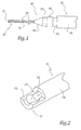
- the cables 52 extend to the distal end of the tube 21, which is formed by a flat lens 21 '( figure 1 ), where they are fixed by any appropriate means.
- the fiberscope of the invention is provided, at the body 10, with a conventional optical system that makes it possible, on the one hand, to send light towards the disc 40 and, on the other hand, to send back an image from the latter.
- a conventional optical system which is for example formed by a succession of lenses, associated with a light source, is represented schematically on the figure 4 , where it is assigned reference 60.
- this optical system may also include an arrangement of optical fibers.
- the separable portion 20 is provided with means for firstly transmitting, towards the distal end of the insertion tube 21, the light coming from the optical system 60, via the discs 40 and 50. These means make it possible to also to bring the image, emitted at this distal end of the tube 21, towards the discs 40 and 50 and, consequently, the optical system 60, so as to allow viewing by the practitioner.
- optical means comprise two bundles of fibers, namely firstly a central cylindrical bundle 70, able to bring the image back from the distal end of the insertion tube 21.
- This bundle 70 is surrounded by an annular peripheral beam 72, for sending the light towards this distal end.
- the central beam 70 is formed by different individual bundles of fibers, of polyhedral shape, which are arranged next to each other.
- the peripheral beam 72 is surrounded by a protective sheath 74, which is for example of a metallic or plastic nature.
- the beams 70 and 72, associated with the sleeve 74, extend beyond the shaft 20 2 of the separable portion 20, so as to form the insertion tube 21, as shown in figure 1 .
- these beams 66 and 72, as well as this sheath 74 are surrounded by the cables 52, which are fixed on the lens 21 'as mentioned above.
- the invention is not limited to the example described and shown.
- discs 40, 50 of optical transmission and mechanical connection according to other arrangements.
- operating channels can be added to different optical fibers, for aspiration, coagulation, or the passage of biopsy forceps or other surgical instruments.
- the two members 40 and 50 can be secured in a removable manner, being removably attached as in the example shown.
- they can also be wedged relative to each other, within their housing, in particular by being pressed against each other, so that they are mutually connected both in rotation and in translation, in use.
- At least one of the two mechanical connection and optical transmission members may be provided with a pivot. This measurement makes it possible to constrain the organ considered to rotate about a single axis.
- the central beam 70 for returning the image from the distal end of the insertion tube to the connection zone, can be formed via separate optical fibers.
- the invention finds application in all fields of human or animal endoscopy.
- these include otorhinolaryngology, digestive endoscopy oeso-gastroduodenal and colic, bronchoscopy, urology or gynecology.
- the invention makes it possible to achieve the objectives mentioned above.
- the insertion tube belonging to the fiberscope of the invention, can be set in motion reliably, thanks to the transmission of printed movements at the handle of the body of the fiberscope.
- Such a mechanical transmission of movements is susceptible to be implemented in all directions, which allows precise guidance of the insertion tube.
- the presence of the discs 40 and 50 which provide an additional function of optical transmission, ensures the transmission of light from the body to the end of the tube, as well as that of the images from this end towards the body.
- each tube is able to be assigned a specific reference.
- the insertion tube of the fiberscope according to the invention can be eliminated in an ecological manner, for example by incineration. This avoids the use of toxic products, including proteolytic products, which are not reprocessed and are eliminated in nature.
- the invention makes it possible to dispense with conventional decontamination operations. In this way, it makes it possible to reduce the workforce in a notable manner, and substantially eliminates the dangerous stains associated with decontamination, which prevails in the prior art.
- the invention also significantly reduces the cost of examinations using fibroscopes.
Landscapes
- Physics & Mathematics (AREA)
- Health & Medical Sciences (AREA)
- Life Sciences & Earth Sciences (AREA)
- Surgery (AREA)
- Optics & Photonics (AREA)
- Biomedical Technology (AREA)
- Radiology & Medical Imaging (AREA)
- Heart & Thoracic Surgery (AREA)
- Pathology (AREA)
- Medical Informatics (AREA)
- Astronomy & Astrophysics (AREA)
- Engineering & Computer Science (AREA)
- Molecular Biology (AREA)
- Nuclear Medicine, Radiotherapy & Molecular Imaging (AREA)
- Biophysics (AREA)
- General Physics & Mathematics (AREA)
- Animal Behavior & Ethology (AREA)
- General Health & Medical Sciences (AREA)
- Public Health (AREA)
- Veterinary Medicine (AREA)
- Endoscopes (AREA)
- Instruments For Viewing The Inside Of Hollow Bodies (AREA)
Abstract
Description
La présente invention concerne un fibroscope à tube d'insertion séparable.The present invention relates to a separable insertion tube fibroscope.
Un fibroscope est un endoscope souple, permettant l'exploration des cavités profondes de l'organisme. A cet effet, ce fibroscope comprend un corps ainsi qu'un tube d'insertion, qui est destiné à pénétrer dans les cavités précitées.A fiberscope is a flexible endoscope, allowing exploration of the deep cavities of the body. For this purpose, this fiberscope comprises a body and an insertion tube, which is intended to penetrate the aforementioned cavities.
Dans un passé récent, les performances des médecines pratiquant l'endoscopie se sont accrues grâce aux progrès technologiques, qui ont permis entre autres la réalisation d'endoscopes de plus en plus petits et, par voie de conséquence, de moins en moins traumatisants pour le patient.In the recent past, the performance of endoscopic medicines has increased thanks to technological progress, which has allowed, among other things, the production of ever smaller and therefore less traumatic endoscopes. patient.
En outre ces examens d'endoscopie, qui sont de plus en plus mis en oeuvre, deviennent indispensables à la pratique quotidienne. Ils permettent, d'une part, un diagnostic rapide et fiable et, d'autre part, le suivi régulier de nombreuses pathologies évitant ainsi, le plus souvent, d'avoir recours à d'autres séries d'examens volontiers plus coûteux ou plus agressifs.In addition, these endoscopy examinations, which are increasingly implemented, become indispensable to daily practice. They allow, on the one hand, a rapid and reliable diagnosis and, on the other hand, the regular monitoring of many pathologies, thus avoiding, in most cases, the use of other series of examinations which are often more expensive or more expensive. aggressive.
Etant donné qu'ils font appel à un appareillage optique et électro-optique sophistiqué, les endoscopes présentent généralement un coût élevé de sorte que, pour des raisons de rentabilité, ils doivent être réutilisés chez un grand nombre de patients. Dans ces conditions, une telle réutilisation nécessite une stérilisation ou, au moins, une désinfection de l'endoscope, entre deux patients successifs.Since they use sophisticated optical and electro-optical equipment, endoscopes are generally expensive, so that, for reasons of cost-effectiveness, they must be reused in a large number of patients. Under these conditions, such reuse requires sterilization or, at least, disinfection of the endoscope, between two successive patients.
Cependant, une telle stérilisation ne s'avère pas toujours totalement fiable, ce qui induit des risques de contamination des patients. En effet, les endoscopes ne résistent pas aux températures très élevées, de sorte que cette stérilisation est opérée par l'intermédiaire de procédures, dont la fiabilité ne peut être considérée comme absolue, en particulier à l'égard de micro-organismes émergents, tel celui de la maladie de Kreuzfeld Jacob.However, such sterilization is not always completely reliable, which induces risks of contamination of patients. Indeed, the endoscopes do not They are not resistant to very high temperatures, so sterilization is performed through procedures, the reliability of which can not be considered absolute, especially with regard to emerging microorganisms, such as Kreuzfeld's disease. Jacob.
De plus, une telle stérilisation est d'une mise en oeuvre relativement longue, ce qui implique l'intervention de personnel spécifique, ainsi que la mise à disposition de locaux et d'équipements de protection individuelle spécifiques. Par ailleurs, cette stérilisation s'accompagne de l'emploi de produits toxiques, dont la durée d'efficacité est limitée dans le temps et qui sont susceptibles d'être dangereux pour l'environnement.In addition, such sterilization is a relatively long implementation, which involves the intervention of specific personnel, as well as the provision of specific premises and personal protective equipment. Moreover, this sterilization is accompanied by the use of toxic products, whose duration of effectiveness is limited in time and which are likely to be dangerous for the environment.
En conclusion, de tels endoscopes se révèlent d'un coût élevé, de sorte que les examens de routine qui en tirent parti sont particulièrement onéreux.In conclusion, such endoscopes prove to be expensive, so routine examinations that take advantage of them are particularly expensive.
Afin de remédier à ces inconvénients, on a proposé, par
Ceci permet de s'affranchir de la mise en oeuvre d'une opération de stérilisation. En effet, le tube souillé n'est plus réutilisé, alors que le corps de l'endoscope, qui se trouve à l'extérieur du patient, n'a pas besoin d'être stérilisé après chaque examen.This makes it possible to dispense with the implementation of a sterilization operation. Indeed, the stained tube is no longer reused, while the body of the endoscope, which is outside the patient, does not need to be sterilized after each examination.
Ceci étant précisé, l'invention se propose de réaliser un fibroscope à tube d'insertion séparable, présentant une structure mécanique simple et un coût de fabrication relativement réduit, tout en tirant parti d'un raccord rapide et commode entre le corps et le tube d'insertion.That being said, the invention proposes to make a fiberscope with separable insertion tube, having a simple mechanical structure and a relatively low manufacturing cost, while taking advantage of a quick and convenient connection between the body and the tube insertion.
A cet effet, elle a pour objet un fibroscope comprenant un corps et un tube d'insertion appartenant à une partie séparable par rapport au corps, ce corps et cette partie séparable étant reliés mécaniquement au niveau d'une zone de raccord, ce fibroscope comprenant également :
- des premiers moyens de guidage dont est pourvu le corps, en particulier un premier jeu de câbles, aptes à être actionnés par un organe de manoeuvre appartenant au corps, en particulier une poignée ;
- des seconds moyens de guidage dont est pourvue la partie séparable, en particulier un second jeu de câbles, aptes à mettre en mouvement le tube d'insertion ;
- des premiers moyens optiques dont est pourvu le corps, aptes à transmettre la lumière vers la zone de raccord et à ramener une image de cette zone de raccord vers une zone de visualisation par un praticien, telle qu'un oculaire ;
- des seconds moyens optiques dont est pourvue la partie séparable, aptes à transmettre la lumière de la zone de raccord vers une extrémité distale du tube d'insertion et à ramener une image de cette extrémité distale du tube d'insertion vers la zone de raccord et
- des premier et second organes de raccord mécanique et de transmission optique, qui sont solidarisés de façon amovible en service, chaque organe étant solidaire de moyens de guidage correspondants de manière à transmettre un mouvement imparti par les premiers moyens de guidage vers les seconds moyens de guidage, ces organes de raccord mécanique et de transmission optique étant également aptes à transmettre la lumière provenant des premiers moyens optiques en direction des seconds moyens optiques et à ramener une image provenant des seconds moyens optiques vers les premiers moyens optiques.
- first guide means of which the body is provided, in particular a first set of cables, adapted to be actuated by an operating member belonging to the body, in particular a handle;
- second guide means which is provided with the separable part, in particular a second set of cables, able to set in motion the insertion tube;
- first optical means of which the body is provided, adapted to transmit the light to the connection zone and to bring an image of this connection zone to a viewing zone by a practitioner, such as an eyepiece;
- second optical means provided with the separable portion, adapted to transmit the light from the connection zone to a distal end of the insertion tube and to bring an image of this distal end of the insertion tube to the connection zone and
- first and second mechanical connection and optical transmission members, which are detachably secured in use, each member being secured to corresponding guide means so as to transmit a movement imparted by the first guide means to the second guide means these mechanical coupling and optical transmission members also being able to transmit light from the first optical means to the second optical means and to bring an image from the second optical means to the first optical means.
Selon d'autres caractéristiques de l'invention :
- la zone de raccord définit un logement possédant des parois intérieures en forme de portion de sphère, alors qu'au moins un parmi les premier et second organes de raccord mécanique et de transmission optique possède des parois extérieures sphériques de diamètre sensiblement égal à celui desdites parois intérieures, de façon à autoriser trois degrés de liberté en rotation, sans aucun degré de liberté en translation, de ces deux organes par rapport aux parois du logement.
- Les premier et second organes de raccord mécanique de transmission optique sont solidarisés de façon amovible, en service, en étant mutuellement fixés de façon amovible.
- Un premier organe de raccord mécanique et de transmission optique, pourvu desdites parois sphériques extérieures, définit une gorge de réception amovible d'un second organe de raccord mécanique et de transmission optique, qui est notamment un disque plan.
- Le premier organe de raccord mécanique et de transmission optique possède deux faces frontales parallèles ainsi qu'une couronne en saillie définissant, avec l'une de ces faces frontales, ladite gorge de réception.
- La zone de raccord comprend deux tronçons de raccord complémentaires, à peu près semi-cylindriques, appartenant respectivement au corps et à la partie séparable, tronçons de raccord dans lesquels sont ménagés des renfoncements correspondants, destinés à former en service ledit logement.
- Les premier et second organes de raccord mécanique et de transmission optique sont solidarisés de façon amovible en service, en étant coincés l'un par rapport à l'autre, notamment par plaquage mutuel.
- Les premiers moyens optiques comprennent une succession de lentilles associées à une source lumineuse.
- Les seconds moyens optiques comprennent un faisceau central de fibres optiques, aptes à ramener une image de l'extrémité distale du tube d'insertion vers la zone de raccord, ainsi qu'un faisceau périphérique de fibres optiques, aptes à transmettre la lumière de la zone de raccord vers cette extrémité distale.
- Le faisceau périphérique est entouré par une gaine, réalisée notamment en un matériau métallique ou plastique.
- Le faisceau central est formé de fibres optiques séparées.
- Le faisceau central est formé par différents faisceaux individuels de fibres optiques, de forme polyédrique, qui sont disposés les uns à côté des autres.
- La zone de raccord est entourée d'un moyen de verrouillage externe, en particulier une bague.
- the connecting zone defines a housing having interior walls in the form of a portion of a sphere, while at least one of the first and second mechanical connection members and optical transmission has outer spherical walls of diameter substantially equal to that of said inner walls, so as to allow three degrees of freedom in rotation, without any degree of freedom in translation, of these two members relative to the walls housing.
- The first and second optical transmission mechanical coupling members are releasably secured in use, mutually releasably secured.
- A first mechanical connection and optical transmission member, provided with said outer spherical walls, defines a removable receiving groove of a second mechanical coupling member and optical transmission, which is in particular a flat disk.
- The first mechanical connection and optical transmission member has two parallel end faces and a projecting ring defining, with one of these end faces, said receiving groove.
- The connection zone comprises two complementary, approximately semi-cylindrical, connecting portions respectively belonging to the body and to the separable part, connecting sections in which recesses are formed corresponding to form said housing in use.
- The first and second mechanical connection members and optical transmission are secured in a removable manner in use, being wedged with respect to each other, in particular by mutual plating.
- The first optical means comprise a succession of lenses associated with a light source.
- The second optical means comprise a central beam of optical fibers capable of reducing a image of the distal end of the insertion tube to the connection zone, and a peripheral beam of optical fibers, capable of transmitting the light from the connection zone to this distal end.
- The peripheral beam is surrounded by a sheath, made in particular of a metallic or plastic material.
- The central beam is formed of separate optical fibers.
- The central beam is formed by different individual optical fiber bundles, of polyhedral shape, which are arranged next to one another.
- The connection zone is surrounded by external locking means, in particular a ring.
L'invention sera mieux comprise et d'autres avantages de celle-ci apparaîtront plus clairement à la lumière de la description qui va suivre d'un fibroscope conforme à son principe, donnée uniquement à titre d'exemple non limitatif et faite en référence aux dessins annexés, dans lesquels :
- la
figure 1 est une vue de face, illustrant schématiquement un fibroscope conforme à l'invention ; - la
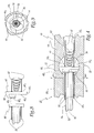
figure 2 est une vue en perspective, illustrant la zone de raccord entre le corps et le tube d'insertion du fibroscope de lafigure 1 ; - la
figure 3 est une vue de côté, illustrant des éléments de transmission optique et de raccord mécanique, intervenant dans le fibroscope desfigures 1 et 2 ; et - la
figure 4 est une vue en coupe longitudinale, illustrant la zone de raccord précitée, dans laquelle sont disposés les organes de transmission optique et de raccord mécanique de lafigure 3 ; - la
figure 5 est une vue en coupe selon la ligne V-V à lafigure 4 .
- the
figure 1 is a front view, schematically illustrating a fiberscope according to the invention; - the
figure 2 is a perspective view illustrating the zone of connection between the body and the insertion tube of the fibroscope of thefigure 1 ; - the
figure 3 is a side view, illustrating elements of optical transmission and mechanical connection, involved in the fiberscope of theFigures 1 and 2 ; and - the
figure 4 is a longitudinal sectional view, illustrating the aforementioned connection zone, in which are arranged the optical transmission members and mechanical coupling of thefigure 3 ; - the
figure 5 is a sectional view along the line VV to thefigure 4 .
Comme le montre notamment la
Le corps 10 comporte un manche 101, prolongé par un fût coaxial 102, de plus faible diamètre. Comme le montrent notamment les
Le fibroscope possède également une partie d'extrémité 20, séparable par rapport au corps 10, qui comprend un fût cylindrique 202, s'étendant dans le prolongement du fût 102 du corps 10. Ce fût 202 est lui-même prolongé par une région de liaison 204, de forme tronconique, qui est terminée par un tube d'insertion 21, destiné à pénétrer dans des cavités profondes du patient. Comme le montre la
Ce corps 10 et cette partie séparable 20 se raccordent mécaniquement, au niveau d'une zone de raccord, qui est formée par deux tronçons de raccord 12 et 22, visibles sur la
Comme le montre cette
Ainsi, en service, les deux tronçons 12 et 22 sont en contact mutuel par leurs méplats respectifs, dont seul celui 121 est illustré. Par ailleurs, les deux renfoncements précités forment un logement 30, présentant des parois 122 et 222 sphériques, dans lequel débouchent les alésages 103 et 203. Cette zone de raccord 12, 22 est entourée par un moyen de verrouillage supplémentaire, qui est en l'occurrence une bague 32.Thus, in use, the two
La
Ce disque 40 est tronqué par une première face frontale 402, sur laquelle est fixé un premier jeu de câbles 42. Ces derniers, qui sont par exemple prévus au moins au nombre de deux, sont fixés sur le disque 40 par tout moyen approprié.This
La seconde face frontale 403 du disque 40, parallèle à celle 402 évoquée ci-dessus, définit avec une couronne d'extrémité 404 une gorge 405. Cette dernière est destinée à la réception d'un disque transparent plat 50 de forme globalement circulaire. Ce disque 50 reçoit un second jeu de câbles 52, prévus au moins au nombre de deux, qui sont fixés par tout moyen approprié.The
En service, comme le montre la
Par conséquent, un déplacement des câbles 42, initié par la poignée, est transmis de façon correspondante aux câbles 52, par l'intermédiaire de ces deux disques 40 et 50. Les câbles 52 s'étendent jusqu'à l'extrémité distale du tube d'insertion 21, qui est formée par une lentille plate 21' (
On conçoit donc que la mise en mouvement précitée des câbles 42, qui induit une mise en mouvement correspondante des câbles 52, provoque un déplacement du tube d'insertion 21, sous la forme d'une torsion. En vue de faciliter un tel mouvement, la paroi extérieure de ce tube 21, qui est formée par une gaine comme on le verra dans ce qui suit, est avantageusement conformée à la manière d'un soufflet.It is thus conceivable that the aforementioned movement of the
Le fibroscope de l'invention est muni, au niveau du corps 10, d'un système optique classique permettant, d'une part, d'envoyer de la lumière en direction du disque 40 et, d'autre part, de renvoyer une image provenant de ce dernier. Un tel système, qui est par exemple formé par une succession de lentilles, associées à une source lumineuse, est représenté de façon schématique sur la
De façon analogue, la partie séparable 20 est pourvue de moyens permettant tout d'abord de transmettre, vers l'extrémité distale du tube d'insertion 21, la lumière provenant du système optique 60, via les disques 40 et 50. Ces moyens permettent également de ramener l'image, émise au niveau de cette extrémité distale du tube 21, en direction des disques 40 et 50 et, par conséquent, du système optique 60, de façon à en autoriser la visualisation par le praticien.Similarly, the
De façon plus précise, de tels moyens optiques comprennent deux faisceaux de fibres, à savoir tout d'abord un faisceau central cylindrique 70, apte à ramener l'image depuis l'extrémité distale du tube d'insertion 21. Ce faisceau 70 est entouré par un faisceau périphérique annulaire 72, destiné à envoyer la lumière en direction de cette extrémité distale.More specifically, such optical means comprise two bundles of fibers, namely firstly a central
Avantageusement, dans une configuration non représentée, le faisceau central 70 est formé par différents faisceaux individuels de fibres, de forme polyédrique, qui sont disposés les uns à côté des autres.Advantageously, in a configuration not shown, the
Comme le montrent notamment les
Après une utilisation du fibroscope de l'invention, il s'agit tout d'abord d'enlever la bague 32, puis de désolidariser la partie séparable 20 du corps 10, en dégageant le disque 50 de la gorge 405. Cette partie séparable, souillée au niveau du tube d'insertion 21, est alors jetée, puis remplacée par une autre partie séparable, de structure analogue, en vue d'une utilisation supplémentaire du fibroscope de l'invention.After using the fiberscope of the invention, it is first necessary to remove the
L'invention n'est pas limitée à l'exemple décrit et représenté.The invention is not limited to the example described and shown.
Ainsi, on peut prévoir de réaliser les disques 40, 50 de transmission optique et de raccord mécanique selon d'autres agencements. Par ailleurs, des canaux opératoires peuvent être adjoints aux différentes fibres optiques, en vue de l'aspiration, de la coagulation, ou encore du passage de pinces à biopsie ou d'autres instruments opératoires.Thus, it is possible to provide the
En service, les deux organes 40 et 50 peuvent être solidarisés de façon amovible, en étant fixés de manière amovible comme dans l'exemple illustré. A titre de variante, ils peuvent également être coincés l'un par rapport à l'autre, au sein de leur logement, notamment en étant plaqués l'un contre l'autre, de sorte qu'ils sont mutuellement liés à la fois en rotation et en translation, en service.In use, the two
A titre de variante supplémentaire, au moins l'un des deux organes de raccord mécanique et de transmission optique peut être pourvu d'un pivot. Cette mesure permet de contraindre l'organe considéré à entrer en rotation, autour d'un unique axe.As a further variant, at least one of the two mechanical connection and optical transmission members may be provided with a pivot. This measurement makes it possible to constrain the organ considered to rotate about a single axis.
A titre de variante supplémentaire, le faisceau central 70, permettant de ramener l'image de l'extrémité distale du tube d'insertion vers la zone de raccord, peut être formé par l'intermédiaire de fibres optiques séparées.As a further alternative, the
L'invention trouve son application à tous les domaines de l'endoscopie humaine ou animale. Dans le domaine médical, il s'agit notamment de l'oto-rhino-laryngologie, de l'endoscopie digestive oeso-gastro-duodénale et colique, de la bronchoscopie, de l'urologie ou encore de la gynécologie.The invention finds application in all fields of human or animal endoscopy. In the medical field, these include otorhinolaryngology, digestive endoscopy oeso-gastroduodenal and colic, bronchoscopy, urology or gynecology.
L'invention permet de réaliser les objectifs précédemment mentionnés.The invention makes it possible to achieve the objectives mentioned above.
Ainsi, le tube d'insertion, appartenant au fibroscope de l'invention, peut être mis en mouvement de manière fiable, grâce à la transmission des mouvements imprimés au niveau de la poignée du corps du fibroscope. Une telle transmission mécanique des mouvements est susceptible d'être mise en oeuvre dans toutes les directions, ce qui autorise un guidage précis du tube d'insertion.Thus, the insertion tube, belonging to the fiberscope of the invention, can be set in motion reliably, thanks to the transmission of printed movements at the handle of the body of the fiberscope. Such a mechanical transmission of movements is susceptible to be implemented in all directions, which allows precise guidance of the insertion tube.
De plus, la présence des disques 40 et 50, qui assurent une fonction supplémentaire de transmission optique, garantit la transmission de la lumière du corps vers l'extrémité du tube, ainsi que celle des images depuis cette extrémité en direction du corps.In addition, the presence of the
En outre, le raccord mécanique, intervenant entre le corps et la partie séparable du fibroscope, est extrêmement simple et rapide à mettre en oeuvre. Ceci offre par conséquent une grande facilité d'utilisation et autorise l'emploi de tubes d'insertion stériles à usage unique. A cet égard, ces tubes d'insertion peuvent être reçus, après stérilisation par radiothérapie, dans des emballages eux aussi stériles, ce qui garantit une asepsie rigoureuse.In addition, the mechanical connection, intervening between the body and the separable portion of the fiberscope, is extremely simple and quick to implement. This therefore offers great ease of use and allows the use of sterile disposable insertion tubes. In this respect, these insertion tubes can be received, after sterilization by radiotherapy, in also sterile packaging, which guarantees a strict asepsis.
Il est également à noter que l'invention introduit une notion de traçabilité des différents tubes d'insertion. Ainsi, chaque tube est à même d'être affecté d'une référence spécifique.It should also be noted that the invention introduces a notion of traceability of the different insertion tubes. Thus, each tube is able to be assigned a specific reference.
Une fois utilisé, le tube d'insertion du fibroscope conforme à l'invention peut être éliminé de façon écologique, par exemple par incinération. Ceci permet d'éviter l'emploi de produits toxiques, notamment protéolytiques, qui ne sont pas retraités et se trouvent éliminés dans la nature.Once used, the insertion tube of the fiberscope according to the invention can be eliminated in an ecological manner, for example by incineration. This avoids the use of toxic products, including proteolytic products, which are not reprocessed and are eliminated in nature.
L'invention permet enfin de s'affranchir des opérations classiques de décontamination. De la sorte, elle permet de réduire la main d'oeuvre d'une façon notable, et supprime sensiblement les taches dangereuses liées à la décontamination, prévalant dans l'art antérieur. L'invention permet également de réduire sensiblement le coût lié aux examens faisant appel à des fibroscopes.Finally, the invention makes it possible to dispense with conventional decontamination operations. In this way, it makes it possible to reduce the workforce in a notable manner, and substantially eliminates the dangerous stains associated with decontamination, which prevails in the prior art. The invention also significantly reduces the cost of examinations using fibroscopes.
Claims (13)
- Fiberscope comprising a body (10) and an insertion tube (21) belonging to a part (20) that is separable from the body (10), this body (10) and this separable part (20) being mechanically joined at a connection zone (12, 22), this fiberscope also comprising:- first guide means belonging to the body (10), in particular a first set of cables (42) that can be operated via a maneuvering element belonging to the body, in particular a handle;- first optical means (60) belonging to the body (10) and able to transmit light to the connection zone (12, 22) and return an image of this connection zone (12, 22) to a zone for viewing by a practitioner, such as an eyepiece;- second optical means (70, 72) belonging to the separable part (20) and able to transmit light from the connection zone (12, 22) to a distal end (21') of the insertion tube (21) and return an image from this distal end of the insertion tube (21) to the connection zone (12, 22), and characterized by- second guide means belonging to the separable part (20), in particular a second set of cables (52) that are able to move the insertion tube (21) and by;- first (40) and second (50) mechanical connection and optical transmission elements which are joined removably in service, each element (40, 50) being integral with corresponding guide means (42, 52) in such a way that a movement imparted by the first guide means (42) can be transmitted to the second guide means (52), these mechanical connection and optical transmission elements (40, 50) also being able to transmit light coming from the first optical means (60) to the second optical means (70, 72) and to return an image from the second optical means (70, 72) to the first optical means (60).
- Fiberscope according to Claim 1, characterized in that the connection zone (12, 22) defines a seat (30) having inner walls (122, 222) in the shape of a portion of a sphere, while at least one of the first (40) and second (50) mechanical connection and optical transmission elements has spherical outer walls (401) with a diameter substantially equal to that of said inner walls, so as to allow three degrees of freedom in rotation, without any degree of freedom in translation, of these two elements relative to the walls of the seat (30).
- Fiberscope according to either of Claims 1 and 2, characterized in that the first (40) and second (50) mechanical connection and optical transmission elements are joined removably, in service, by being mutually fixed in a removable manner.
- Fiberscope according to either of Claims 2 and 3, characterized in that a first (40) mechanical connection and optical transmission element, provided with said outer spherical walls (401), defines a groove (405) for receiving, in a removable manner, a second (50) mechanical connection and optical transmission element, which is in particular a plane disk.
- Fiberscope according to Claim 4, characterized in that the first (40) mechanical connection and optical transmission element has two parallel front faces (402, 403) and a protruding crown (404) defining, with one (403) of these front faces, said receiving groove (405).
- Fiberscope according to any one of Claims 2 to 5, characterized in that the connection zone comprises two complementary, almost semicylindrical connection portions (12, 22) belonging respectively to the body (10) and to the separable part (20), in which connection portions corresponding recesses are formed which are intended to form said seat (30) in service.
- Fiberscope according to either of Claims 1 and 2, characterized in that the first and second mechanical connection and optical transmission elements are joined removably in service by being wedged relative to one another, in particular by being pressed flat against one another.
- Fiberscope according to any one of the preceding claims, characterized in that the first optical means (60) comprise a succession of lenses associated with a light source.
- Fiberscope according to any one of the preceding claims, characterized in that the second optical means comprise a central bundle (70) of optical fibers that are able to return an image from the distal end of the insertion tube (21) to the connection zone (12, 22), and also a peripheral bundle (72) of optical fibers that are able to transmit light from the connection zone (12, 22) to this distal end.
- Fiberscope according to Claim 9, characterized in that the peripheral bundle (72) is surrounded by a sheath (74), in particular made of a metal or plastic material.
- Fiberscope according to Claim 9 or 10, characterized in that the central bundle (70) is made up of separate optical fibers.
- Fiberscope according to Claim 9 or 10, characterized in that the central bundle is formed by different individual bundles of optical fibers of polyhedral shape which are disposed side by side one another.
- Fiberscope according to any one of the preceding claims, characterized in that the connection zone (12, 22) is surrounded by an external locking means, in particular a ring (32)
Applications Claiming Priority (2)
| Application Number | Priority Date | Filing Date | Title |
|---|---|---|---|
| FR0311438A FR2860135B1 (en) | 2003-09-30 | 2003-09-30 | FIBROSCOPE WITH SEPARABLE INSERTION TUBE |
| PCT/FR2004/002465 WO2005032353A1 (en) | 2003-09-30 | 2004-09-29 | Fiberscope with a separable insertion tube |
Publications (2)
| Publication Number | Publication Date |
|---|---|
| EP1667571A1 EP1667571A1 (en) | 2006-06-14 |
| EP1667571B1 true EP1667571B1 (en) | 2009-03-25 |
Family
ID=34307275
Family Applications (1)
| Application Number | Title | Priority Date | Filing Date |
|---|---|---|---|
| EP04817092A Not-in-force EP1667571B1 (en) | 2003-09-30 | 2004-09-29 | Fiberscope with a separable insertion tube |
Country Status (7)
| Country | Link |
|---|---|
| US (1) | US20070073101A1 (en) |
| EP (1) | EP1667571B1 (en) |
| JP (1) | JP2007507266A (en) |
| AT (1) | ATE426355T1 (en) |
| DE (1) | DE602004020240D1 (en) |
| FR (1) | FR2860135B1 (en) |
| WO (1) | WO2005032353A1 (en) |
Families Citing this family (2)
| Publication number | Priority date | Publication date | Assignee | Title |
|---|---|---|---|---|
| US9155454B2 (en) | 2010-09-28 | 2015-10-13 | Smith & Nephew, Inc. | Hysteroscopic system |
| JPWO2013132744A1 (en) * | 2012-03-09 | 2015-07-30 | コニカミノルタ株式会社 | In-vivo observation fiberscope |
Family Cites Families (16)
| Publication number | Priority date | Publication date | Assignee | Title |
|---|---|---|---|---|
| DE3327933A1 (en) * | 1982-08-04 | 1984-02-09 | Olympus Optical Co., Ltd., Tokyo | INSERT FOR AN INDUSTRIAL ENDOSCOPE |
| JPS5922411U (en) * | 1982-08-04 | 1984-02-10 | オリンパス光学工業株式会社 | Sheath fixation device for industrial endoscope insertion section |
| US4624243A (en) * | 1985-04-08 | 1986-11-25 | American Hospital Supply Corp. | Endoscope having a reusable eyepiece and a disposable distal section |
| JPS6395030A (en) * | 1986-10-08 | 1988-04-26 | オリンパス光学工業株式会社 | Connector for endoscope |
| US4782819A (en) * | 1987-02-25 | 1988-11-08 | Adair Edwin Lloyd | Optical catheter |
| US4911148A (en) * | 1989-03-14 | 1990-03-27 | Intramed Laboratories, Inc. | Deflectable-end endoscope with detachable flexible shaft assembly |
| US4919112B1 (en) * | 1989-04-07 | 1993-12-28 | Low-cost semi-disposable endoscope | |
| US5549542A (en) * | 1992-11-17 | 1996-08-27 | Life Medical Technologies, Inc. | Deflectable endoscope |
| US5423312A (en) * | 1992-12-18 | 1995-06-13 | Schott Fiber Optics, Inc. | Rigid endoscope having modified high refractive index tunnel rod for image transmission and method of manufacture thereof |
| AU6158196A (en) * | 1995-06-07 | 1996-12-30 | Robert T. Chilcoat | Articulated endospcope with specific advantages for laryngos copy |
| US5733242A (en) * | 1996-02-07 | 1998-03-31 | Rayburn; Robert L. | Intubation system having an axially moveable memory cylinder |
| US6004263A (en) * | 1996-03-13 | 1999-12-21 | Hihon Kohden Corporation | Endoscope with detachable operation unit and insertion unit |
| US5960145A (en) * | 1997-01-21 | 1999-09-28 | Sanchez; Jorge O. | Optical fiber image conduit and method using same |
| WO2002062262A2 (en) * | 2001-02-02 | 2002-08-15 | Insight Instruments, Inc. | Endoscope system and method of use |
| EP1408846B1 (en) * | 2001-06-29 | 2012-03-07 | Intuitive Surgical Operations, Inc. | Platform link wrist mechanism |
| US7241263B2 (en) * | 2004-09-30 | 2007-07-10 | Scimed Life Systems, Inc. | Selectively rotatable shaft coupler |
-
2003
- 2003-09-30 FR FR0311438A patent/FR2860135B1/en not_active Expired - Fee Related
-
2004
- 2004-09-29 EP EP04817092A patent/EP1667571B1/en not_active Not-in-force
- 2004-09-29 AT AT04817092T patent/ATE426355T1/en not_active IP Right Cessation
- 2004-09-29 JP JP2006530405A patent/JP2007507266A/en active Pending
- 2004-09-29 WO PCT/FR2004/002465 patent/WO2005032353A1/en active Application Filing
- 2004-09-29 DE DE602004020240T patent/DE602004020240D1/en active Active
- 2004-09-29 US US10/573,963 patent/US20070073101A1/en not_active Abandoned
Also Published As
| Publication number | Publication date |
|---|---|
| WO2005032353A1 (en) | 2005-04-14 |
| FR2860135B1 (en) | 2005-12-02 |
| US20070073101A1 (en) | 2007-03-29 |
| JP2007507266A (en) | 2007-03-29 |
| FR2860135A1 (en) | 2005-04-01 |
| EP1667571A1 (en) | 2006-06-14 |
| DE602004020240D1 (en) | 2009-05-07 |
| ATE426355T1 (en) | 2009-04-15 |
Similar Documents
| Publication | Publication Date | Title |
|---|---|---|
| EP2768373B1 (en) | Steerable endoscope comprising a brake | |
| JP3393539B2 (en) | Endoscope device | |
| EP1493379B1 (en) | Removable switching device for endoscopic probe for medical use | |
| KR101226839B1 (en) | A hand piece for the delievery of light | |
| US6749344B2 (en) | Connection apparatus for optical coherence tomography catheters | |
| US8485968B2 (en) | Endoscope | |
| US7736301B1 (en) | Rotatable ferrules and interfaces for use with an optical guidewire | |
| EP2007270B1 (en) | Protection for endoscope, and corresponding endoscope | |
| JP2018517440A (en) | Endoscope, endoscope cap, and endoscope cap forming method | |
| EP2789290B1 (en) | Device for acquiring images of a region of a human or animal body | |
| US20020166946A1 (en) | Optical scanning probe device using low coherence light | |
| JP2009119064A (en) | Cover type endoscope, endoscope for cover, and endoscope cover | |
| JP2000097845A5 (en) | ||
| JP6467061B2 (en) | Endoscope | |
| JP2018517442A (en) | Endoscope, endoscope cap, and endoscope cap forming method | |
| EP1667571B1 (en) | Fiberscope with a separable insertion tube | |
| JP2009160224A (en) | Separate type endoscope | |
| US5951463A (en) | Hand-held endoscopic viewing system | |
| JP3386187B2 (en) | Rigid endoscope device | |
| WO2010133810A1 (en) | Medical instrument with multiple functions for an endoscope | |
| US20150219436A1 (en) | Optical probe and method of attaching optical probe | |
| WO2011083217A2 (en) | Video endoscope | |
| CN114569040A (en) | Endoscope device supporting disassembly and assembly | |
| FR2926715A1 (en) | Distal tip deflection controlling device for e.g. laparoscope, has fingers arranged so that one finger is co-operated with reliefs when other finger is situated between reliefs, and pulley whose diameter is smaller than that of other pulley | |
| FR3113367A1 (en) | STERILE COVER AND ROTATING JOINT DEVICE |
Legal Events
| Date | Code | Title | Description |
|---|---|---|---|
| PUAI | Public reference made under article 153(3) epc to a published international application that has entered the european phase |
Free format text: ORIGINAL CODE: 0009012 |
|
| 17P | Request for examination filed |
Effective date: 20060320 |
|
| AK | Designated contracting states |
Kind code of ref document: A1 Designated state(s): AT BE BG CH CY CZ DE DK EE ES FI FR GB GR HU IE IT LI LU MC NL PL PT RO SE SI SK TR |
|
| DAX | Request for extension of the european patent (deleted) | ||
| GRAP | Despatch of communication of intention to grant a patent |
Free format text: ORIGINAL CODE: EPIDOSNIGR1 |
|
| RAP1 | Party data changed (applicant data changed or rights of an application transferred) |
Owner name: DIOPTIK SAS |
|
| RIN1 | Information on inventor provided before grant (corrected) |
Inventor name: JOUINEAU, FRANCOIS Inventor name: QUEYROUX, ALAIN Inventor name: FAUGERAS, PIERRE |
|
| GRAS | Grant fee paid |
Free format text: ORIGINAL CODE: EPIDOSNIGR3 |
|
| GRAA | (expected) grant |
Free format text: ORIGINAL CODE: 0009210 |
|
| AK | Designated contracting states |
Kind code of ref document: B1 Designated state(s): AT BE BG CH CY CZ DE DK EE ES FI FR GB GR HU IE IT LI LU MC NL PL PT RO SE SI SK TR |
|
| REG | Reference to a national code |
Ref country code: GB Ref legal event code: FG4D Free format text: NOT ENGLISH |
|
| REG | Reference to a national code |
Ref country code: CH Ref legal event code: EP |
|
| REG | Reference to a national code |
Ref country code: IE Ref legal event code: FG4D Free format text: LANGUAGE OF EP DOCUMENT: FRENCH |
|
| REF | Corresponds to: |
Ref document number: 602004020240 Country of ref document: DE Date of ref document: 20090507 Kind code of ref document: P |
|
| PG25 | Lapsed in a contracting state [announced via postgrant information from national office to epo] |
Ref country code: SI Free format text: LAPSE BECAUSE OF FAILURE TO SUBMIT A TRANSLATION OF THE DESCRIPTION OR TO PAY THE FEE WITHIN THE PRESCRIBED TIME-LIMIT Effective date: 20090325 Ref country code: FI Free format text: LAPSE BECAUSE OF FAILURE TO SUBMIT A TRANSLATION OF THE DESCRIPTION OR TO PAY THE FEE WITHIN THE PRESCRIBED TIME-LIMIT Effective date: 20090325 |
|
| PG25 | Lapsed in a contracting state [announced via postgrant information from national office to epo] |
Ref country code: PL Free format text: LAPSE BECAUSE OF FAILURE TO SUBMIT A TRANSLATION OF THE DESCRIPTION OR TO PAY THE FEE WITHIN THE PRESCRIBED TIME-LIMIT Effective date: 20090325 Ref country code: AT Free format text: LAPSE BECAUSE OF FAILURE TO SUBMIT A TRANSLATION OF THE DESCRIPTION OR TO PAY THE FEE WITHIN THE PRESCRIBED TIME-LIMIT Effective date: 20090325 Ref country code: SE Free format text: LAPSE BECAUSE OF FAILURE TO SUBMIT A TRANSLATION OF THE DESCRIPTION OR TO PAY THE FEE WITHIN THE PRESCRIBED TIME-LIMIT Effective date: 20090625 |
|
| NLV1 | Nl: lapsed or annulled due to failure to fulfill the requirements of art. 29p and 29m of the patents act | ||
| REG | Reference to a national code |
Ref country code: IE Ref legal event code: FD4D |
|
| PG25 | Lapsed in a contracting state [announced via postgrant information from national office to epo] |
Ref country code: ES Free format text: LAPSE BECAUSE OF FAILURE TO SUBMIT A TRANSLATION OF THE DESCRIPTION OR TO PAY THE FEE WITHIN THE PRESCRIBED TIME-LIMIT Effective date: 20090706 Ref country code: EE Free format text: LAPSE BECAUSE OF FAILURE TO SUBMIT A TRANSLATION OF THE DESCRIPTION OR TO PAY THE FEE WITHIN THE PRESCRIBED TIME-LIMIT Effective date: 20090325 Ref country code: CZ Free format text: LAPSE BECAUSE OF FAILURE TO SUBMIT A TRANSLATION OF THE DESCRIPTION OR TO PAY THE FEE WITHIN THE PRESCRIBED TIME-LIMIT Effective date: 20090325 |
|
| PGFP | Annual fee paid to national office [announced via postgrant information from national office to epo] |
Ref country code: FR Payment date: 20090812 Year of fee payment: 6 Ref country code: MC Payment date: 20090818 Year of fee payment: 6 |
|
| PG25 | Lapsed in a contracting state [announced via postgrant information from national office to epo] |
Ref country code: SK Free format text: LAPSE BECAUSE OF FAILURE TO SUBMIT A TRANSLATION OF THE DESCRIPTION OR TO PAY THE FEE WITHIN THE PRESCRIBED TIME-LIMIT Effective date: 20090325 Ref country code: NL Free format text: LAPSE BECAUSE OF FAILURE TO SUBMIT A TRANSLATION OF THE DESCRIPTION OR TO PAY THE FEE WITHIN THE PRESCRIBED TIME-LIMIT Effective date: 20090325 Ref country code: RO Free format text: LAPSE BECAUSE OF FAILURE TO SUBMIT A TRANSLATION OF THE DESCRIPTION OR TO PAY THE FEE WITHIN THE PRESCRIBED TIME-LIMIT Effective date: 20090325 |
|
| PGFP | Annual fee paid to national office [announced via postgrant information from national office to epo] |
Ref country code: CH Payment date: 20090915 Year of fee payment: 6 Ref country code: GB Payment date: 20090904 Year of fee payment: 6 Ref country code: LU Payment date: 20090911 Year of fee payment: 6 |
|
| PG25 | Lapsed in a contracting state [announced via postgrant information from national office to epo] |
Ref country code: IE Free format text: LAPSE BECAUSE OF FAILURE TO SUBMIT A TRANSLATION OF THE DESCRIPTION OR TO PAY THE FEE WITHIN THE PRESCRIBED TIME-LIMIT Effective date: 20090325 Ref country code: DK Free format text: LAPSE BECAUSE OF FAILURE TO SUBMIT A TRANSLATION OF THE DESCRIPTION OR TO PAY THE FEE WITHIN THE PRESCRIBED TIME-LIMIT Effective date: 20090325 Ref country code: BG Free format text: LAPSE BECAUSE OF FAILURE TO SUBMIT A TRANSLATION OF THE DESCRIPTION OR TO PAY THE FEE WITHIN THE PRESCRIBED TIME-LIMIT Effective date: 20090625 |
|
| PGFP | Annual fee paid to national office [announced via postgrant information from national office to epo] |
Ref country code: DE Payment date: 20090911 Year of fee payment: 6 |
|
| PLBE | No opposition filed within time limit |
Free format text: ORIGINAL CODE: 0009261 |
|
| STAA | Information on the status of an ep patent application or granted ep patent |
Free format text: STATUS: NO OPPOSITION FILED WITHIN TIME LIMIT |
|
| 26N | No opposition filed |
Effective date: 20091229 |
|
| PGFP | Annual fee paid to national office [announced via postgrant information from national office to epo] |
Ref country code: BE Payment date: 20091020 Year of fee payment: 6 |
|
| PG25 | Lapsed in a contracting state [announced via postgrant information from national office to epo] |
Ref country code: GR Free format text: LAPSE BECAUSE OF FAILURE TO SUBMIT A TRANSLATION OF THE DESCRIPTION OR TO PAY THE FEE WITHIN THE PRESCRIBED TIME-LIMIT Effective date: 20090626 |
|
| BERE | Be: lapsed |
Owner name: DIOPTIK SAS Effective date: 20100930 |
|
| PG25 | Lapsed in a contracting state [announced via postgrant information from national office to epo] |
Ref country code: IT Free format text: LAPSE BECAUSE OF FAILURE TO SUBMIT A TRANSLATION OF THE DESCRIPTION OR TO PAY THE FEE WITHIN THE PRESCRIBED TIME-LIMIT Effective date: 20090325 |
|
| PG25 | Lapsed in a contracting state [announced via postgrant information from national office to epo] |
Ref country code: MC Free format text: LAPSE BECAUSE OF NON-PAYMENT OF DUE FEES Effective date: 20100930 |
|
| REG | Reference to a national code |
Ref country code: CH Ref legal event code: PL |
|
| GBPC | Gb: european patent ceased through non-payment of renewal fee |
Effective date: 20100929 |
|
| REG | Reference to a national code |
Ref country code: FR Ref legal event code: ST Effective date: 20110531 |
|
| PG25 | Lapsed in a contracting state [announced via postgrant information from national office to epo] |
Ref country code: HU Free format text: LAPSE BECAUSE OF FAILURE TO SUBMIT A TRANSLATION OF THE DESCRIPTION OR TO PAY THE FEE WITHIN THE PRESCRIBED TIME-LIMIT Effective date: 20090926 |
|
| REG | Reference to a national code |
Ref country code: DE Ref legal event code: R119 Ref document number: 602004020240 Country of ref document: DE Effective date: 20110401 |
|
| PG25 | Lapsed in a contracting state [announced via postgrant information from national office to epo] |
Ref country code: LI Free format text: LAPSE BECAUSE OF NON-PAYMENT OF DUE FEES Effective date: 20100930 Ref country code: FR Free format text: LAPSE BECAUSE OF NON-PAYMENT OF DUE FEES Effective date: 20100930 Ref country code: BE Free format text: LAPSE BECAUSE OF NON-PAYMENT OF DUE FEES Effective date: 20100930 Ref country code: CH Free format text: LAPSE BECAUSE OF NON-PAYMENT OF DUE FEES Effective date: 20100930 Ref country code: DE Free format text: LAPSE BECAUSE OF NON-PAYMENT OF DUE FEES Effective date: 20110401 |
|
| PG25 | Lapsed in a contracting state [announced via postgrant information from national office to epo] |
Ref country code: GB Free format text: LAPSE BECAUSE OF NON-PAYMENT OF DUE FEES Effective date: 20100929 Ref country code: TR Free format text: LAPSE BECAUSE OF FAILURE TO SUBMIT A TRANSLATION OF THE DESCRIPTION OR TO PAY THE FEE WITHIN THE PRESCRIBED TIME-LIMIT Effective date: 20090325 |
|
| PG25 | Lapsed in a contracting state [announced via postgrant information from national office to epo] |
Ref country code: CY Free format text: LAPSE BECAUSE OF FAILURE TO SUBMIT A TRANSLATION OF THE DESCRIPTION OR TO PAY THE FEE WITHIN THE PRESCRIBED TIME-LIMIT Effective date: 20090325 |
|
| PG25 | Lapsed in a contracting state [announced via postgrant information from national office to epo] |
Ref country code: PT Free format text: LAPSE BECAUSE OF FAILURE TO SUBMIT A TRANSLATION OF THE DESCRIPTION OR TO PAY THE FEE WITHIN THE PRESCRIBED TIME-LIMIT Effective date: 20090825 Ref country code: LU Free format text: LAPSE BECAUSE OF NON-PAYMENT OF DUE FEES Effective date: 20100929 |