EP1667084B1 - Detection of the desired stop - Google Patents
Detection of the desired stop Download PDFInfo
- Publication number
- EP1667084B1 EP1667084B1 EP05300960A EP05300960A EP1667084B1 EP 1667084 B1 EP1667084 B1 EP 1667084B1 EP 05300960 A EP05300960 A EP 05300960A EP 05300960 A EP05300960 A EP 05300960A EP 1667084 B1 EP1667084 B1 EP 1667084B1
- Authority
- EP
- European Patent Office
- Prior art keywords
- stop
- vehicle
- receiving device
- destination
- stops
- Prior art date
- Legal status (The legal status is an assumption and is not a legal conclusion. Google has not performed a legal analysis and makes no representation as to the accuracy of the status listed.)
- Active
Links
- 238000001514 detection method Methods 0.000 title claims description 7
- 238000000034 method Methods 0.000 claims abstract description 8
- 238000012545 processing Methods 0.000 claims description 10
- 238000011144 upstream manufacturing Methods 0.000 claims description 3
- 230000004044 response Effects 0.000 claims description 2
- 230000001755 vocal effect Effects 0.000 claims 1
- 238000010586 diagram Methods 0.000 description 8
- 230000005540 biological transmission Effects 0.000 description 7
- 238000013459 approach Methods 0.000 description 6
- 238000007726 management method Methods 0.000 description 4
- 238000004891 communication Methods 0.000 description 2
- 238000005516 engineering process Methods 0.000 description 2
- 230000001771 impaired effect Effects 0.000 description 2
- 230000004807 localization Effects 0.000 description 2
- 238000010200 validation analysis Methods 0.000 description 2
- 238000012550 audit Methods 0.000 description 1
- 238000012790 confirmation Methods 0.000 description 1
- 238000009434 installation Methods 0.000 description 1
- 238000004519 manufacturing process Methods 0.000 description 1
- 230000005855 radiation Effects 0.000 description 1
- 238000012546 transfer Methods 0.000 description 1
- 230000001960 triggered effect Effects 0.000 description 1
Images


Classifications
-
- G—PHYSICS
- G08—SIGNALLING
- G08G—TRAFFIC CONTROL SYSTEMS
- G08G1/00—Traffic control systems for road vehicles
- G08G1/123—Traffic control systems for road vehicles indicating the position of vehicles, e.g. scheduled vehicles; Managing passenger vehicles circulating according to a fixed timetable, e.g. buses, trains, trams
- G08G1/133—Traffic control systems for road vehicles indicating the position of vehicles, e.g. scheduled vehicles; Managing passenger vehicles circulating according to a fixed timetable, e.g. buses, trains, trams within the vehicle ; Indicators inside the vehicles or at stops
Definitions
- the present invention relates to an on-board assistance system for the users of a vehicle serving several predetermined stops and a support infrastructure using such a support system.
- the assistance system of the present invention is particularly suitable for buses but can be applied in different modes of public transport, such as the metro, urban or regional trains, for example.
- a system for assisting a public transport user is described in document GB 2 322 725, in which a portable reception device comprising a receiver allows the user to be warned when approaching a predetermined destination stop.
- Transmitters capable of transmitting a radio frequency signal comprising an identification code are arranged near said stops. Each transmitter continuously transmits the identification code associated with it. When the vehicle enters the range of the transmitter, it receives the corresponding code. The receiving device compares the received code and the destination code that it has in memory to determine if the destination station is approaching. In the case where the destination station is approaching, the receiving device warns the user.
- programming terminals allow the programming of reception devices.
- Such a support system nevertheless has several disadvantages.
- Such a support system is complicated and expensive to deploy, since each stop, or more generally each place whose approach must be signaled, requires the installation of a transmitter.
- such transmitters are not protected from vandalism or natural wear and tear.
- such an assistance system can easily be disturbed by the radiation of other devices, especially in urban areas, which can lead to reception problems.
- such a support system is difficult to evolve, since each change of a path requires re-installing new transmitters, which requires long and expensive work.
- the present invention aims to provide an assistance system that avoids at least some of the aforementioned drawbacks.
- Another object of the invention is to provide a scalable assistance system, easy to deploy, which allows a user to be notified when approaching a predetermined stop.
- the invention relates to an assistance system for the users of a vehicle serving a transmission line including several predetermined stops which are associated predetermined stopping identification codes, said assistance system comprising a radiofrequency transmitter for transmitting, to a portable reception device, one of said identification codes corresponding to a stop near which said vehicle is located, characterized in that said assistance system is embedded in said vehicle, said assistance system comprising a satellite location receiver able to determine a current position of said vehicle from signals emitted by satellites, a geographical database defining a proximity zone associated with each of said stops, a processing means adapted to detect, from said current position, the presence of said vehicle in a e of said proximity zones and, whenever the presence of the vehicle is detected in one of said proximity zones, to select said stop identification code associated with the stop in the zone of proximity from which the presence of said vehicle is detected and controlling said transmitter to transmit said selected identification code said radiofrequency transmitter being arranged in said vehicle so as to transmit, at least inside said vehicle, said selected identification code.
- the stops and the proximity zones are defined by data recorded in the on-board assistance system, it is very simple to adapt them to any transmission line whatever the positions of the stops.
- This assistance system is therefore more flexible than assistance system using fixed transmitters, for which the proximity area, which is equal to the range of the transmitter, is difficult to control.
- the proximity zones may be of any shape.
- said geographical database comprises data defining each of said proximity zones by a respective polygon whose vertices are defined by latitudes and longitudes stored in said geographical database.
- said geographical database defines said proximity zones so as to position each of said proximity zones substantially upstream of said associated stop with respect to the direction of movement of the vehicle in which said stop is served.
- Such a definition of the proximity zones makes it possible to warn the user with a certain advance and to avoid detecting a stop already passed.
- said assistance system comprises a traffic direction indicator for indicating a current direction of movement of said vehicle, said geographical database comprising data defining, for each of said stops, a direction of circulation of the vehicle in which said stop is likely to be served, said processing means being able to select stops likely to be served in the current direction of the vehicle to detect the presence of the vehicle only among the areas of proximity associated with said selected stops.
- said processing means is adapted to position said traffic direction indicator in response to the detection of the presence of the vehicle in the proximity zone of a terminus of said transport line.
- said processing means is adapted to position said traffic direction indicator in response to the detection of the presence of the vehicle in the proximity zone of a terminus of said transport line.
- said geographical database comprises data defining the names of said stops, an identical stop identification code being associated with several of said stops bearing the same name and served in different traffic directions.
- said geographical database comprises data defining the names of said stops, an identical stop identification code being associated with several of said stops bearing the same name and served in different traffic directions.
- said geographical database includes a file by stopping the transport line, said file including a stop name, a direction of service and a definition of proximity zone.
- said assistance system comprises a programming device disposed in said vehicle, said programming device comprising a user-operable input interface for selecting a destination stop and an output interface. intended to cooperate with said receiving device for storing in said receiving device a destination code corresponding to said destination stop.
- said destination code is identical to the stop identification code associated with said selected destination stop.
- the destination code, sent by the programming device is not necessarily identical to the identification code, transmitted by the radiofrequency transmitter, of the destination stop, since the receiver can carry out a correspondence between these codes.
- said input interface comprises a touch screen for displaying a list of stops of said transmission line. It is also possible to provide any type of input interface on the programming devices, for example an input interface comprising a voice recognition module.
- said output interface comprises a radio frequency transmitter.
- said programming device comprises a correspondence management module able to identify a correspondence stop, where the user must change the transmission line, and another transport line that the user must use to reach his stop of destination.
- the subject of the invention is also an assistance infrastructure characterized in that it comprises a support system mentioned above and a portable reception device, said reception device comprising a receiver able to receive said stop identification code. transmitted by the radiofrequency transmitter when said receiving device is inside said vehicle, said receiving device comprising a memory capable of storing a destination code, corresponding to a destination stop desired by the user, said receiving device comprising comparison means adapted to compare said destination code and said received identification code and said reception device comprising alert means adapted to alert the user of a correspondence between said stored destination code and said code stop identification received.
- said receiving device is integrated in a mobile phone.
- said receiving device comprises a voice recognition module for voice programming said at least one destination station in said receiving device.
- said alerting means comprises a light warning means.
- said alerting means comprises an audible warning means.
- said warning system comprises a means of vibration.
- said method comprises a step of storing in said receiving device a destination code by means of a programming terminal, said programming terminal comprising an input interface for selecting the destination stop.
- said method comprises the steps of determining, with the aid of said programming terminal, a correspondence stop where the user must change lines to reach said destination stop and to store in said reception device an identification code. said judgment of correspondence.
- a bus 1 intended to serve several predetermined stops 11a, 11b, 13a, 13b, 15a and 15b (FIG. 3) along a transport line L1 (FIGS. 3 and 6). ) having two terminals A and B.
- the bus 1 is equipped with an onboard assistance system 2.
- the assistance system 2 comprises a satellite positioning system 3, a computer 4 and a transmitter 5.
- Each stop 11a, 11b, 13a, 13b, 15a and 15b or terminus A and B has an identification code which is associated.
- This assistance system is intended to form an assistance infrastructure in association with portable devices for bus users.
- all the buses serving this line L1 are equipped in the same way.
- the location system 3 is a GPS receiver, which is able to determine a current position of the bus 1 from signals emitted by satellites 6, in a manner known per se.
- the GPS receiver 3 transmits the current position data in the form of a latitude-longitude pair to the computer 4.
- the computer 4 is intended to process the signals received by the GPS receiver 3.
- the computer 4 comprises a geographic database 7 which includes files 7a, for example in XML.
- files 7a for example in XML.
- File 7a contains data called "service direction".
- the direction of service corresponds to the direction of movement of the bus 1 in which the stop 15a is likely to be served.
- the value "1" corresponds to a stop served when the bus is traveling on the line L1 in the direction of the arrow 16, and the value "0" corresponds to a stop served when the bus is traveling in the direction of the arrow 17.
- the file 7a contains location data, between the ⁇ location> line and the ⁇ / location> line.
- the location data makes it possible to define a rectangular proximity zone 14a associated with the stop 15a, by specifying the geographical data of the vertices of a rectangle, namely two latitudes and two longitudes.
- this rectangle is specified by an upper left vertex (UL) and a lower right vertex (DR).
- the file 7a also contains information data relating to the stop 15a, between the line ⁇ info> and the line ⁇ / info>, namely the name of the stop 15a, that is to say GARE , and the line L1 on which the stop 15a is located. This information data is intended to be transmitted to the receiving device 20, in a manner to be described in detail below.
- the stops 11a and 11b bear the same name, namely THEATER
- judgments 13a and 13b bear the same name, namely MAIRIE
- both judgments 15a and 15b bear the same name, namely GARE.
- the stops 11a, 13a and 15a are served when the bus 1 circulates in the street 18 in the direction of the arrow 16 and the stops 11b, 13b and 15b are served when the bus 1 circulates in the street 18 in the direction of the arrow 17.
- Nearby areas are also associated with all stops, including Terminals A and B. Street 18 has two lanes 18a and 18b, separated by a line 19.
- Each zone 10a, 10b, 12a, 12b, 14a or 14b extends upstream of the stop 11a, 11b, 13a, 13b, 15a or 15b with which it is associated.
- the size of an area is defined as the area that defines it.
- the size of each zone 10a, 10b, 12a, 12b, 14a or 14b is defined independently of the size of the other zones. For example, when the bus 1 flows in the direction of the arrow 16, if the stop 13a is close to the stop 15a, it is not desired that the stop 13a is announced before the bus 1 stops at judgment 15a.
- the zone 12a must therefore be sufficiently small so that the zone 12a does not contain the stop 15a.
- stop 11a can influence the size of the zones 10a, 10b, 12a, 12b, 14a and 14b. For example, if the stop 11a is located on a fast lane it can be defined by a relatively large area 10a because the bus 1 can get there faster than elsewhere and the users must be warned with a certain advance notice, therefore sufficiently far from stop 11a.
- the stops and the proximity zones are defined by data recorded in the on-board assistance system, it is very simple to adapt to any transmission line regardless of the positions of the stops, which are not necessarily face to face.
- the computer 4 includes a position indicator that corresponds to the direction of movement of the bus.
- the position indicator is updated with each change of direction, as will be described in detail below.
- the position indicator is an integer variable.
- the position indicator is "1" when bus 1 runs in the direction of arrow 16 and "0" when bus 1 is traveling in the direction of arrow 17.
- the computer 4 is also equipped with an operating system, for example linux or windows.
- the definition files of the proximity zones 7a can be updated by copying files (floppy disk, USB key, etc.). It is therefore very simple to update the assistance system 2, for example when the path of the bus 1 changes.
- the computer 4 is connected to the transmitter 5.
- the transmitter 5 is a radio frequency transmitter which emits for example in the 433 MHZ band.
- the signal emitted by the transmitter 5 has for example a power of about 1 mW and a range of about 200-300m. However, a range of approximately 10m is generally sufficient to cover the interior space of the bus 1.
- the power can be adapted to reduce the coverage area.
- a programming terminal 30 is shown for programming the reception device 20.
- a programming terminal 30 can be arranged in the bus 1, as can be seen in FIG. 1.
- the terminal 30 includes an interface input in the form of a touch screen 31 allowing a bus user to choose the destination stop where the user wants to go down and whose identification code must be stored in the memory 24 as the destination code.
- the screen 31 includes a menu 32 for selecting each of the stops 11a, 11b, 13a, 13b, 15a, 15b, A or B of the line L1. Arrows 33 make it possible to go through the list 34 of the stops 11a, 11b, 13a, 13b, 15a and 15b including the terminals A and B on the line L1.
- the terminal 30 also has an output interface in the form of a radio frequency transmitter 36 for transmitting to a receiving device 20 the programming data.
- the transmission is a transmission at very short range to avoid programming other receiving devices 20 that may be nearby.
- the transmitter 36 operates at the same frequency as the transmitter 5, which makes it possible to use a single corresponding receiver in the reception device 20.
- a receiving device 20 which comprises a housing 26.
- the receiving device 20 comprises a receiver 22 adapted to the transmitter 5, adapted to receive signals in the 433 MHz band.
- the architecture of the receiving device 20 is based on a microprocessor BasicStamp type 21 associated with a module RF / 433MHz 22.
- the receiving device 20 comprises a display screen 23, for example a LCD display 2 * 16 characters.
- the receiving device 20 also comprises a memory 24, for example of the EPROM type, which enables it to memorize the destination codes associated with the desired destination stops by the user.
- the receiving device 20 also comprises an alert system 27, for example an audible alarm.
- the receiving device 20 also comprises control buttons 25, which allow the user to control the receiving device 20 for example to turn it on or off.
- Step 70 is to detect the current position of the bus 1 with the GPS receiver 3.
- position data is received by the GPS receiver 3, it transmits it to the computer 4 and proceeds to step 71.
- Step 71 compares the received position data with the proximity associated with the starting terminals of the bus 1, namely for example the terminals A and B.
- the computer 4 compares the proximity area defined in each of the two files 7a associated with the terminus of departure with the position data received.
- step 72 which consists of adjusting the value of the position indicator to indicate the direction of movement of the bus 1 from this terminus of departure, namely for example the direction 16 from the terminus A and the direction 17 from the terminus B. Then we return to step 70. Otherwise, we return to step 70.
- the departure terminus and the terminus of arrival of a bus at a given location are not necessarily confused. It is quite possible to provide a proximity zone associated with the stop where the passengers are coming down (terminus of arrival) and a zone of proximity associated with the stop where the passengers go up (terminus of departure).
- the step 80 is to select in the programming terminal 30 the desired destination stop from the list of all the stops 11a, 11b, 13a, 13b, 15a or 15b including the terminus A or B. This selection is made using the touch screen 31.
- Step 81 is an optional step that is not used in this embodiment and will be described in detail later.
- the step 82 consists in transmitting a signal containing the identification code and the name of the destination stop selected by the user, the signal being sent by the terminal 30 to the receiving device 20.
- the transmitted signal also includes a programming instruction, to indicate to the reception device 20 that the identification code and the name must be stored in the memory 24.
- a audible signal for validation of the reception device 20 confirms the registration of the destination code and the stop name in the memory 24.
- the user can perform this programming when it is mounted in the bus 1 or during its journey.
- Step 90 consists of to detect the current position of the bus 1 with the GPS receiver 3.
- the computer 4 compares the received position data with the proximity zones 10a, 10b, 12a, 12b, 14a and 14b associated with each stop 11a, 11b, 13a, 13b, 15a and 15b including each terminus A and B.
- the computer 4 analyzes each file 7a.
- the computer 4 For each file 7a, the computer 4 begins by comparing the value of the direction of service mentioned in the file 7a with the value of the position indicator. If they are identical, the computer 4 compares the latitude and longitude provided by the GPS receiver 3 with the latitudes and longitudes of the vertices of the proximity area defined in the file 7a. If the current position of the bus 1 is not in this zone, the computer 4 proceeds to the next file 7a. If the position data does not correspond to any zone near the stops of the line, it returns to step 90. As long as the bus 1 is not in an area close to the stops of the line, then one carries out a loop between step 90 and step 91.
- bus 1 is considered to be running on line L1 in the direction of arrow 16.
- GPS receiver 3 receives position data and step 91 is carried out.
- step 91 the computer 4 makes the comparisons.
- it analyzes the file 7a associated with the zone 14a, it detects that the value of the service direction of this file 7a is equal to the value of the position indicator.
- the computer 4 therefore compares the current position data of the bus 1 with the proximity zone 14a defined in this file 7a. The computer 4 thus detects that the bus 1 is in the zone 14a, so that the bus 1 approaches the stop 15a, and one goes to the step 92.
- the step 92 consists of controlling the transmitter 5 to it emits a modulated signal containing the identification code corresponding to the stop 15a.
- the emitted signal also includes a detection instruction, to indicate to the receiving device 20 that the identification code must be compared with the stored destination code.
- the identification code When the identification code has been issued, it returns to step 90. Thus, this loop is performed continuously by the embedded system.
- the housing 26 is portable and transported by the user who is in the bus 1. For example, it is considered that the user wishes to go to the stop 13a and that he programmed his receiving device 20 accordingly.
- FIG. 10 there is shown a block diagram describing the steps performed by the reception device 20 to alert the user when approaching his destination stop 11a, 11b, 13a, 13b, 15a or 15b. Including terminus A or B.
- Step 100 consists of receiving an identification code transmitted by the transmitter 5.
- the reception device 20 receives an identification code, it proceeds to step 101.
- the step 101 is to compare the received identification code with the stored destination code.
- step 102 When the receiving device 20 receives the identification code corresponding to the stop 15a, it compares it with the destination code corresponding to the stop 13a but there is no equality, so we return to the step 100, as indicated by the arrow 103.
- the device 20 receives the code corresponding to the stop 13a, it goes to the step 101 and compares the codes. Since the identification code received by the reception device 20 corresponds to the destination code stored in the memory 24, step 102 is proceeded to.
- the step 102 consists in alerting the user by a sound or vibration signal and display on the screen 23 the name of the destination stop previously stored in the memory 24. The user can stop the notification sent by his reception device by the use of the buttons 25. Alternatively, the stop name could be issued by the transmitter 5 each time it issues a stop identification code.
- step 102 has been performed, return to step 100.
- a terminal 30 is disposed in each of the buses 1.
- terminals 30 may be outside the buses 1, for example in bus shelters or correspondence nodes.
- the terminal 30 includes the list of all the stops of the transport network, namely for example all stops lines L1, L2 and L3 and allows the user to select any of these stops as a desired destination.
- the terminal 30 is connected to the computer 4.
- the computer 4 transmits in real time current position data from the bus 1 to the terminal 30.
- the programming terminal 30 has a correspondence management module, which enables it to determine the correspondences that the user must perform.
- the correspondences are the line changes that the user may have to make to get to his destination stop.
- the bus stops are the stops where the user must change lines to reach his destination stop.
- programming of the receiving device 20 includes step 81.
- Step 80 corresponds to selecting the destination stop, in the same manner as in the first mode of production.
- a user takes the bus 1 of the line L1 and wants to go to the terminus C of the line L3, he selects this destination in the programming terminal 30 inside the bus 1.
- the programming terminal 30 determines the shortest path to go from the current position of the bus 1 to the terminus C using its correspondence management module .
- Step 182 consists of transmitting a programming instruction and destination data, namely the identification code and the name of the destination stop.
- the terminal 30 transmits the identification code and the stop name corresponding to the stop where the user must leave the first line, ie, for example, stop 15a, and a frame containing information on the second line and the direction that the user must take, that is to say for example the line L2 direction D.
- the following correspondence is identified by the identification code and the name corresponding to the stop where the user must leave the second line, namely the stop 9 and a frame containing information relating to the third line and the direction that the user must take, that is to say line L3 and direction C.
- the warning system 27 is triggered in the same manner as in the first embodiment.
- the screen 23 displays the name of the stop 15a and the line L2 that the user must take to arrive at the terminus C, as shown in Figure 11.
- the user does not need to program his reception device 20 since the latter has already memorized the destination stop C, as well as the corresponding correspondence stop 9.
- the receiving device 20 makes it possible to alert the user at each correspondence stop 15a and 9 by indicating which line to take L2 and L3, then to alert him when approaching the stop of destination C.
- the correspondence management can be used on a transport network which comprises any number of lines and any number of matches between the lines.
- This assistance system 2 is adapted to a transport network using buses 1, but can also be used on any type of transport network.
- the receiving device 20 which is programmed by voice.
- the receiving device has a memory for previously storing the name of the stops and the identification codes of all the stops of the line.
- This is equipped with a voice recognition module to program the name of the desired destination stop.
- a switch toggles the receiving device into voice programming mode. he Just say the name of the destination stop. If the name is recognized by the module, that is to say if the name has been memorized, it will emit a confirmation tone.
- a separate programming terminal is not necessary in this case.
- the receiving device can permanently display the current station as well as the destination stop that it has in memory, as shown in FIG. 12.
- the receiving device 20 can be integrated in a mobile phone equipped with a wireless communication technology, for example WiFi technology. In this case, the programming terminals 30 are no longer needed.
- an application can be downloaded automatically, after validation of the user, when the phone is in the WiFi zone of bus 1.
- the warning means 27 may be arbitrary, such as light, sound, vibration or display.
- the vibration of the receiving device 20 at the approach of its destination stop allows it to be autonomous to use public transport.
- the receiving device may comprise control buttons for entering programming mode or erasing the memory 24.
- a radiofrequency link between the programming terminal 30 and the receiving device 20 is particularly suitable since it makes it possible to program the reception device 20 even if it remains in the user's pocket, since this type of connection is little directive. Nevertheless, the programming of the reception device 20 can be carried out with an infrared link or by any other means of data transfer.
- the location of the terminals 30 in bus shelters, railway stations or airports.
- the programming terminals 30 can be coupled to ATM terminals already existing in the stations. With the purchase of the ticket, the receiving device 20 can thus be automatically programmed with the chosen destination.
- the destination codes transmitted by the terminals 30 when programming the reception device 20 may be different from the identification codes issued by the on-board assistance system when the reception device 20 has a correspondence rule. between the stored destination codes and the received identification codes.
- the proximity zones 10a, 10b, 12a, 12b, 14a and 14b can be defined in the form of any polygon whose vertices are marked by their latitude and longitude. Other geometric shapes are still possible.
- the XML localization files 7a can be updated by a means of communication (Satellite, WiFi, etc.) if the embedded computer 4 has such means.
- the 433 MHz is a free band that is suitable for this type of application. Transmitters of this type are known and inexpensive. Nevertheless, the system can operate on another frequency band (2.4 GHz, Wifi for example).
- the traffic direction indicator can be initialized using a manual setting.
- the computer may include an additional file with the order of the stops, to analyze the files 7a in the order of the stops to save time. Such scheduling can also be done using pointers present in each file 7a. Each pointer pointing to file 7a corresponding to the next stop.
Abstract
Description
La présente invention se rapporte à un système d'assistance embarqué pour les usagers d'un véhicule desservant plusieurs arrêts prédéterminés et une infrastructure d'assistance utilisant un tel système d'assistance.The present invention relates to an on-board assistance system for the users of a vehicle serving several predetermined stops and a support infrastructure using such a support system.
Lorsqu'un usager des transports en commun utilise le bus sur un trajet qu'il ne connaît pas, il arrive parfois que celui-ci oublie de descendre car le nom de l'arrêt n'est pas toujours très visible et/ou qu'il lui est difficile de suivre le parcours en l'absence de plan à l'intérieur des bus. La solution la plus courante consiste à demander au chauffeur de prévenir l'usager à l'approche de l'arrêt souhaité. Bien souvent, les demandes se multiplient lorsque le bus parcourt une zone industrielle ou un endroit touristique. De plus, les personnes malvoyantes ont également un problème pour descendre à la bonne station en l'absence de message sonore.When a public transport user uses the bus on a route that he does not know, he may sometimes forget to go down because the name of the bus stop is not always very visible and / or when it is difficult for him to follow the route in the absence of a plane inside the buses. The most common solution is to ask the driver to warn the user when the desired stop is coming. Quite often, the demands multiply when the bus goes through an industrial zone or a tourist place. In addition, visually impaired people also have a problem getting off at the right station in the absence of a sound message.
Le système d'assistance de la présente invention est particulièrement adapté aux bus mais peut s'appliquer dans différents modes de transports en commun, comme le métro, les trains urbains ou régionaux, par exemple.The assistance system of the present invention is particularly suitable for buses but can be applied in different modes of public transport, such as the metro, urban or regional trains, for example.
Un système d'assistance d'un usager des transports en commun est décrit dans le document GB 2 322 725, dans lequel un dispositif de réception portatif comportant un récepteur permet à l'usager d'être prévenu lors de l'approche d'un arrêt de destination prédéterminé. Des émetteurs aptes à émettre un signal radio fréquence comportant un code d'identification sont disposés à proximité desdits arrêts. Chaque émetteur transmet en continu le code d'identification qui lui est associé. Lorsque le véhicule entre dans la zone de portée de l'émetteur, il reçoit le code correspondant. Le dispositif de réception compare le code reçu et le code de destination qu'il a en mémoire pour déterminer si la station de destination approche. Dans le cas où la station de destination approche, le dispositif de réception avertit l'usager. En outre, des bornes de programmation permettent la programmation des dispositifs de réception.A system for assisting a public transport user is described in
Un tel système d'assistance présente néanmoins plusieurs inconvénients. Un tel système d'assistance est compliqué et coûteux à déployer, puisque chaque arrêt, ou plus généralement chaque endroit dont l'approche doit être signalée, nécessite l'installation d'un émetteur. De plus, de tels émetteurs ne sont pas protégés du vandalisme ou de l'usure naturelle. En outre, un tel système d'assistance peut facilement être perturbé par le rayonnement d'autres dispositifs, surtout en milieu urbain, ce qui peut conduire à des problèmes de réception. De plus, un tel système d'assistance est difficilement évolutif, puisque chaque modification d'un trajet impose de réinstaller de nouveaux émetteurs, ce qui nécessite des travaux longs et coûteux.Such a support system nevertheless has several disadvantages. Such a support system is complicated and expensive to deploy, since each stop, or more generally each place whose approach must be signaled, requires the installation of a transmitter. In addition, such transmitters are not protected from vandalism or natural wear and tear. In addition, such an assistance system can easily be disturbed by the radiation of other devices, especially in urban areas, which can lead to reception problems. In addition, such a support system is difficult to evolve, since each change of a path requires re-installing new transmitters, which requires long and expensive work.
La présente invention a pour but de proposer un système d'assistance qui évite au moins certains des inconvénients précités. Un autre but de l'invention est de fournir un système d'assistance évolutif, simple à déployer, qui permet à un usager d'être averti lors de l'approche d'un arrêt prédéterminé.The present invention aims to provide an assistance system that avoids at least some of the aforementioned drawbacks. Another object of the invention is to provide a scalable assistance system, easy to deploy, which allows a user to be notified when approaching a predetermined stop.
A cet effet, l'invention a pour objet un système d'assistance pour les usagers d'un véhicule desservant une ligne de transport incluant plusieurs arrêts prédéterminés auxquels sont associés des codes d'identification d'arrêt prédéterminés, ledit système d'assistance comportant un émetteur radiofréquence pour émettre, à destination d'un dispositif de réception portatif, un desdits codes d'identification correspondant à un arrêt à proximité duquel ledit véhicule se trouve, caractérisé en ce que ledit système d'assistance est embarqué dans ledit véhicule, ledit système d'assistance comportant un récepteur de localisation par satellite apte à déterminer une position courante dudit véhicule à partir de signaux émis par des satellites, une base de données géographiques définissant une zone de proximité associée à chacun desdits arrêts, un moyen de traitement apte à détecter, à partir de ladite position courante, la présence dudit véhicule dans une desdites zones de proximité et, à chaque fois que la présence du véhicule est détectée dans une desdites zones de proximité, à sélectionner ledit code d'identification d'arrêt associé à l'arrêt dans la zone de proximité duquel la présence dudit véhicule est détectée et à commander ledit émetteur pour émettre ledit code d'identification sélectionné ledit émetteur radiofréquence étant agencé dans ledit véhicule de manière à émettre, au moins à l'intérieur dudit véhicule, ledit code d'identification sélectionné.For this purpose, the invention relates to an assistance system for the users of a vehicle serving a transmission line including several predetermined stops which are associated predetermined stopping identification codes, said assistance system comprising a radiofrequency transmitter for transmitting, to a portable reception device, one of said identification codes corresponding to a stop near which said vehicle is located, characterized in that said assistance system is embedded in said vehicle, said assistance system comprising a satellite location receiver able to determine a current position of said vehicle from signals emitted by satellites, a geographical database defining a proximity zone associated with each of said stops, a processing means adapted to detect, from said current position, the presence of said vehicle in a e of said proximity zones and, whenever the presence of the vehicle is detected in one of said proximity zones, to select said stop identification code associated with the stop in the zone of proximity from which the presence of said vehicle is detected and controlling said transmitter to transmit said selected identification code said radiofrequency transmitter being arranged in said vehicle so as to transmit, at least inside said vehicle, said selected identification code.
Comme les arrêts et les zones de proximité sont définis par des données enregistrées dans le système d'assistance embarqué, il est très simple de les adapter à toute ligne de transport quelles que soient les positions des arrêts. Ce système d'assistance est donc plus flexible qu'un système d'assistance utilisant des émetteurs fixes, pour lesquels la zone de proximité, qui est égale à la portée de l'émetteur, est difficile à maîtriser.Since the stops and the proximity zones are defined by data recorded in the on-board assistance system, it is very simple to adapt them to any transmission line whatever the positions of the stops. This assistance system is therefore more flexible than assistance system using fixed transmitters, for which the proximity area, which is equal to the range of the transmitter, is difficult to control.
Les zones de proximité peuvent être de forme quelconque. Selon un mode de réalisation particulier de l'invention, ladite base de données géographiques comporte des données définissant chacune desdites zones de proximité par un polygone respectif dont les sommets sont définis par des latitudes et des longitudes mémorisées dans ladite base de données géographiques.The proximity zones may be of any shape. According to a particular embodiment of the invention, said geographical database comprises data defining each of said proximity zones by a respective polygon whose vertices are defined by latitudes and longitudes stored in said geographical database.
De préférence, ladite base de données géographique définit lesdites zones de proximité de manière à positionner chacune desdites zones de proximité essentiellement en amont dudit arrêt associé par rapport au sens de circulation du véhicule dans lequel ledit arrêt est desservi.Preferably, said geographical database defines said proximity zones so as to position each of said proximity zones substantially upstream of said associated stop with respect to the direction of movement of the vehicle in which said stop is served.
Une telle définition des zones de proximité permet de prévenir l'usager avec une certaine avance et d'éviter de détecter un arrêt déjà passé.Such a definition of the proximity zones makes it possible to warn the user with a certain advance and to avoid detecting a stop already passed.
Selon un autre mode de réalisation particulier de l'invention, ledit système d'assistance comporte un indicateur de sens de circulation pour indiquer un sens de circulation actuel dudit véhicule, ladite base de données géographiques comportant des données définissant, pour chacun desdits arrêts, un sens de circulation du véhicule dans lequel ledit arrêt est susceptible d'être desservi, ledit moyen de traitement étant apte à sélectionner des arrêts susceptibles d'être desservis dans le sens de circulation actuel du véhicule pour détecter la présence du véhicule seulement parmi les zones de proximité associées auxdits arrêts sélectionnés.According to another particular embodiment of the invention, said assistance system comprises a traffic direction indicator for indicating a current direction of movement of said vehicle, said geographical database comprising data defining, for each of said stops, a direction of circulation of the vehicle in which said stop is likely to be served, said processing means being able to select stops likely to be served in the current direction of the vehicle to detect the presence of the vehicle only among the areas of proximity associated with said selected stops.
L'utilisation d'un tel indicateur de sens de circulation est particulièrement intéressante dans le cas où deux arrêts face à face dans une rue. Ainsi, même si des arrêts desservis dans des sens opposés ont des zones de proximité qui se recouvrent, on évite de signaler la proximité de l'arrêt qui ne va pas être desservi.The use of such a traffic sense indicator is particularly interesting in the case where two stops facing each other in a street. Thus, even if stops served in opposite directions have overlapping proximity zones, the proximity of the stop that is not going to be served is avoided.
Avantageusement, ledit moyen de traitement est apte à positionner ledit indicateur de sens de circulation en réponse à la détection de la présence du véhicule dans la zone de proximité d'un terminus de ladite ligne de transport. Ainsi, on détecte simplement et automatiquement le sens de circulation actuel.Advantageously, said processing means is adapted to position said traffic direction indicator in response to the detection of the presence of the vehicle in the proximity zone of a terminus of said transport line. Thus, one simply and automatically detects the current direction of circulation.
De préférence, ladite base de données géographiques comporte des données définissant les noms desdits arrêts, un code d'identification d'arrêt identique étant associé à plusieurs desdits arrêts portant le même nom et desservis dans des sens de circulation différents. Ainsi, on assure la détection de l'arrêt de destination quel que soit le sens par lequel on l'atteint.Preferably, said geographical database comprises data defining the names of said stops, an identical stop identification code being associated with several of said stops bearing the same name and served in different traffic directions. Thus, it ensures the detection of the destination stop regardless of the direction by which it is reached.
Avantageusement, ladite base de données géographiques inclut un fichier par arrêt de la ligne de transport, ledit fichier comportant un nom d'arrêt, un sens de desserte et une définition de zone de proximité.Advantageously, said geographical database includes a file by stopping the transport line, said file including a stop name, a direction of service and a definition of proximity zone.
Dans un mode de réalisation de l'invention, ledit système d'assistance comporte un dispositif de programmation disposé dans ledit véhicule, ledit dispositif de programmation comportant une interface d'entrée actionnable par un utilisateur pour sélectionner un arrêt de destination et une interface de sortie destinée à coopérer avec ledit dispositif de réception pour mémoriser dans ledit dispositif de réception un code de destination correspondant audit arrêt de destination.In one embodiment of the invention, said assistance system comprises a programming device disposed in said vehicle, said programming device comprising a user-operable input interface for selecting a destination stop and an output interface. intended to cooperate with said receiving device for storing in said receiving device a destination code corresponding to said destination stop.
Avantageusement, ledit code de destination est identique au code d'identification d'arrêt associé audit arrêt de destination sélectionné. En variante, le code de destination, émis par le dispositif de programmation, n'est pas nécessairement identique au code d'identification, émis par l'émetteur radiofréquence, de l'arrêt de destination, dès lors que le récepteur peut effectuer une correspondance entre ces codes.Advantageously, said destination code is identical to the stop identification code associated with said selected destination stop. As a variant, the destination code, sent by the programming device, is not necessarily identical to the identification code, transmitted by the radiofrequency transmitter, of the destination stop, since the receiver can carry out a correspondence between these codes.
Selon un mode de réalisation particulier de l'invention, ladite interface d'entrée comporte un écran tactile pour afficher une liste des arrêts de ladite ligne de transport. On peut aussi prévoir tout type d'interface d'entrée sur les dispositifs de programmation, par exemple une interface d'entrée comportant un module de reconnaissance vocale.According to a particular embodiment of the invention, said input interface comprises a touch screen for displaying a list of stops of said transmission line. It is also possible to provide any type of input interface on the programming devices, for example an input interface comprising a voice recognition module.
Avantageusement, ladite interface de sortie comprend un émetteur radiofréquence.Advantageously, said output interface comprises a radio frequency transmitter.
De préférence, ledit dispositif de programmation comporte un module de gestion des correspondances apte à identifier un arrêt de correspondance, où l'usager doit changer de ligne de transport, et une autre ligne de transport que l'usager doit emprunter pour atteindre son arrêt de destination.Preferably, said programming device comprises a correspondence management module able to identify a correspondence stop, where the user must change the transmission line, and another transport line that the user must use to reach his stop of destination.
L'invention a également pour objet une infrastructure d'assistance caractérisée en ce qu'elle comprend un système d'assistance susmentionné et un dispositif de réception portatif, ledit dispositif de réception comportant un récepteur apte à recevoir ledit code d'identification d'arrêt émis par l'émetteur radiofréquence lorsque ledit dispositif de réception est à l'intérieur dudit véhicule, ledit dispositif de réception comportant une mémoire apte à mémoriser un code de destination, correspondant à un arrêt de destination souhaité par l'usager, ledit dispositif de réception comportant un moyen de comparaison apte à comparer ledit code de destination et ledit code d'identification reçu et ledit dispositif de réception comportant un moyen d'alerte apte à alerter l'usager d'une correspondance entre ledit code de destination mémorisé et ledit code d'identification d'arrêt reçu.The subject of the invention is also an assistance infrastructure characterized in that it comprises a support system mentioned above and a portable reception device, said reception device comprising a receiver able to receive said stop identification code. transmitted by the radiofrequency transmitter when said receiving device is inside said vehicle, said receiving device comprising a memory capable of storing a destination code, corresponding to a destination stop desired by the user, said receiving device comprising comparison means adapted to compare said destination code and said received identification code and said reception device comprising alert means adapted to alert the user of a correspondence between said stored destination code and said code stop identification received.
Dans un mode de réalisation de l'invention, ledit dispositif de réception est intégré dans un téléphone portable.In one embodiment of the invention, said receiving device is integrated in a mobile phone.
De préférence, ledit dispositif de réception comporte un module de reconnaissance vocale permettant la programmation vocale de ladite au moins une station de destination dans ledit dispositif de réception.Preferably, said receiving device comprises a voice recognition module for voice programming said at least one destination station in said receiving device.
Avantageusement, ledit moyen d'alerte comprend un moyen d'alerte lumineux.Advantageously, said alerting means comprises a light warning means.
Avantageusement, ledit moyen d'alerte comprend un moyen d'alerte sonore.Advantageously, said alerting means comprises an audible warning means.
Avantageusement, ledit système d'alerte comprend un moyen de vibration.Advantageously, said warning system comprises a means of vibration.
L'invention a également pour objet un procédé d'assistance pour un usager d'un véhicule desservant plusieurs arrêts prédéterminés, caractérisé en ce qu'il comprend les étapes consistant à :
- mémoriser dans un dispositif de réception un code de destination correspondant à un arrêt de destination souhaité par l'usager ;
- transporter l'usager muni dudit dispositif de réception avec le véhicule ;
- déterminer une position courante dudit véhicule à partir de signaux émis par des satellites, à l'aide d'un récepteur de localisation par satellite embarqué dans le véhicule ;
- comparer à l'aide d'un moyen de traitement embarqué dans ledit véhicule ladite position courante du véhicule avec des zones de proximité associées à chacun desdits arrêts, lesdites zones de proximité étant définies dans une base de données géographiques, ladite base de données géographiques embarquée dans ledit véhicule ;
- à chaque fois que la présence du véhicule est détectée dans une desdites zones de proximité, sélectionner à l'aide dudit moyen de traitement un code d'identification d'arrêt associé à un arrêt dans la zone de proximité duquel la présence du véhicule est détectée ;
- émettre ledit code d'identification d'arrêt sélectionné à l'intérieur dudit véhicule ;
- comparer dans ledit dispositif de réception ledit code d'identification émis et ledit code de destination mémorisé ; et
- alerter l'usager si ledit code d'identification émis correspond audit code de destination mémorisé.
- storing in a receiving device a destination code corresponding to a destination stop desired by the user;
- transporting the user equipped with said receiving device with the vehicle;
- determining a current position of said vehicle from signals transmitted by satellites, using a satellite location receiver embedded in the vehicle;
- comparing, using a processing means embedded in said vehicle, said current position of the vehicle with proximity zones associated with each of said stops, said proximity zones being defined in a geographic database, said on-board geographical database in said vehicle;
- whenever the presence of the vehicle is detected in one of said proximity zones, selecting with said processing means a stop identification code associated with a stop in the proximity zone from which the presence of the vehicle is detected ;
- transmitting said selected stop identification code within said vehicle;
- comparing in said receiving device said transmitted identification code and said stored destination code; and
- alert the user if said transmitted identification code corresponds to said stored destination code.
Avantageusement, ledit procédé comprend une étape consistant à mémoriser dans ledit dispositif de réception un code de destination à l'aide d'une borne de programmation, ladite borne de programmation comportant une interface d'entrée pour sélectionner l'arrêt de destination.Advantageously, said method comprises a step of storing in said receiving device a destination code by means of a programming terminal, said programming terminal comprising an input interface for selecting the destination stop.
Avantageusement, ledit procédé comprend les étapes consistant à déterminer à l'aide de ladite borne de programmation un arrêt de correspondance où l'usager doit changer de ligne pour atteindre ledit arrêt de destination et à mémoriser dans ledit dispositif de réception un code d'identification dudit arrêt de correspondance.Advantageously, said method comprises the steps of determining, with the aid of said programming terminal, a correspondence stop where the user must change lines to reach said destination stop and to store in said reception device an identification code. said judgment of correspondence.
L'invention sera mieux comprise, et d'autre buts, détails, caractéristiques et avantages de celle-ci apparaîtront plus clairement au cours de la description explicative détaillée qui va suivre, de plusieurs modes de réalisation de l'invention donnés à titre d'exemples purement illustratifs et non limitatifs, en référence aux dessins schématiques annexés.The invention will be better understood, and other objects, details, features and advantages thereof will become more clearly apparent in the following detailed explanatory description of several embodiments of the invention given as examples. purely illustrative and non-limiting examples, with reference to the attached schematic drawings.
Sur ces dessins :
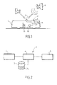
- la figure 1 est une vue simplifiée d'un véhicule équipé d'un système d'assistance selon un mode de réalisation de l'invention ;
- la figure 2 est une vue schématique fonctionnelle du système d'assistance de la figure 1 ;
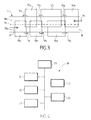
- la figure 3 est une vue schématique de dessus montrant six arrêts situés dans une rue et leurs zones de proximité respectives ;
- la figure 4 est une vue schématique fonctionnelle d'un dispositif de réception ;
- la figure 5 est une vue schématique extérieure du dispositif de réception de la figure 4 et d'une borne de programmation ;
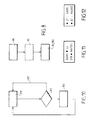
- la figure 6 est une vue schématique d'un réseau de transport sur lequel est utilisé le système d'assistance de la figure 1 ;
- la figure 7 est un schéma fonctionnel représentant les étapes d'une opération d'initialisation du système d'assistance de la figure 1 ;
- la figure 8 est un schéma fonctionnel représentant les étapes d'une opération de programmation du dispositif de réception de la figure 4 ;
- la figure 9 est un schéma fonctionnel représentant les étapes d'une opération de détection de l'approche d'un arrêt à l'aide du système d'assistance de la figure 1 ;
- la figure 10 est un schéma fonctionnel représentant les étapes d'une opération d'alerte à l'aide du dispositif de réception de la figure 4 ; et
- les figures 11 et 12 sont des vues schématiques représentant l'écran du dispositif de réception de la figure 4.
- Figure 1 is a simplified view of a vehicle equipped with an assistance system according to one embodiment of the invention;
- Figure 2 is a schematic functional view of the assistance system of Figure 1;
- Figure 3 is a schematic top view showing six stops located in a street and their respective proximity areas;
- Figure 4 is a schematic functional view of a receiving device;
- Figure 5 is an external schematic view of the receiving device of Figure 4 and a programming terminal;
- FIG. 6 is a schematic view of a transport network on which the assistance system of FIG. 1 is used;
- Fig. 7 is a block diagram showing the steps of an initialization operation of the assistance system of Fig. 1;
- Fig. 8 is a block diagram showing the steps of a programming operation of the receiving device of Fig. 4;
- Fig. 9 is a block diagram showing the steps of an operation of detecting the approach of a stop using the assistance system of Fig. 1;
- Fig. 10 is a block diagram showing the steps of an alert operation using the receiving device of Fig. 4; and
- Figures 11 and 12 are schematic views showing the screen of the receiving device of Figure 4.
En se référant aux figures 1 et 2, on voit un autobus 1 destiné à desservir plusieurs arrêts 11a, 11b, 13a, 13b, 15a et 15b (figure 3) prédéterminés, le long d'une ligne de transport L1 (figures 3 et 6) comportant deux terminus A et B. Le bus 1 est équipé d'un système d'assistance 2 embarqué. Le système d'assistance 2 comporte un système de localisation par satellite 3, un ordinateur 4 et un émetteur 5. Chaque arrêt 11a, 11b, 13a, 13b, 15a et 15b ou terminus A et B a un code d'identification qui lui est associé. Ce système d'assistance est destiné à former une infrastructure d'assistance en association avec des dispositifs portatifs pour les usagers du bus. De préférence, tous les bus desservant cette ligne L1 sont équipés de la même manière.Referring to FIGS. 1 and 2, there is shown a bus 1 intended to serve several
Le système de localisation 3 est un récepteur GPS, qui est apte à déterminer une position courante du bus 1 à partir de signaux émis par des satellites 6, de manière connue en soi. Le récepteur GPS 3 transmet les données de position courante sous la forme d'un couple latitude longitude à l'ordinateur 4.The location system 3 is a GPS receiver, which is able to determine a current position of the bus 1 from signals emitted by
L'ordinateur 4 est destiné à traiter les signaux reçus par le récepteur GPS 3. Pour cela, l'ordinateur 4 comporte une base de données géographique 7 qui comporte des fichiers 7a, par exemple en langage XML. Il y a un fichier 7a associé à chaque arrêt 11a, 11b, 13a, 13b, 15a et 15b y compris chaque terminus A et B.The computer 4 is intended to process the signals received by the GPS receiver 3. For this, the computer 4 comprises a
En se référant à l'annexe 1, on voit le fichier 7a associé à l'arrêt 15a. Le fichier 7a contient des données appelées « sens de desserte ». Le sens de desserte correspond au sens de circulation du bus 1 dans lequel l'arrêt 15a est susceptible d'être desservi. La valeur « 1 » correspond à un arrêt desservi lorsque le bus circule sur la ligne L1 dans le sens de la flèche 16, et la valeur « 0 » correspond à un arrêt desservi lorsque le bus circule dans le sens de la flèche 17. Le fichier 7a contient des données de localisation, comprises entre la ligne <localisation> et la ligne </localisation>. Les données de localisation permettent de définir une zone de proximité 14a rectangulaire associée à l'arrêt 15a, en spécifiant les données géographiques des sommets d'un rectangle à savoir deux latitudes et deux longitudes. Dans l'exemple de l'annexe 1, ce rectangle est spécifié par un sommet supérieur gauche (UL) et un sommet inférieur droit (DR). Le fichier 7a contient également des données d'information relatives à l'arrêt 15a, comprises entre la ligne <info> et la ligne </info>, à savoir le nom de l'arrêt 15a, c'est-à-dire GARE, et la ligne L1 sur laquelle l'arrêt 15a est situé. Ces données d'information sont destinées à être transmises au dispositif de réception 20, d'une manière qui sera décrite en détail plus loin.Referring to Appendix 1, we see file 7a associated with
En se référant à la figure 3, on voit les deux zones de proximité 10a et 10b associées aux deux arrêts 11a et 11b situés face à face dans une rue 18, les deux zones de proximité 12a et 12b associées aux deux arrêts 13a et 13b situés face à face dans la rue 18 et les deux zones de proximité 14a et 14b associées aux deux arrêts 15a et 15b situés face à face dans la rue 18. Par exemple, les arrêts 11a et 11b portent le même nom, à savoir THEATRE, les arrêts 13a et 13b portent le même nom, à savoir MAIRIE et les deux arrêts 15a et 15b portent le même nom, à savoir GARE. Les arrêts 11a, 13a et 15a sont desservis lorsque le bus 1 circule dans la rue 18 dans le sens de la flèche 16 et les arrêts 11b, 13b et 15b sont desservis lorsque le bus 1 circule dans la rue 18 dans le sens de la flèche 17. Des zones de proximité (non représentées) sont également associées à tous les arrêts, y compris aux terminus A et B. La rue 18 comporte deux voies de circulation 18a et 18b, séparées par une ligne 19.Referring to FIG. 3, we see the two
Lorsque deux arrêts face à face portent le même nom, il peut être intéressant de leur attribuer le même code d'identification, afin de simplifier la programmation du dispositif de réception 20, comme cela sera décrit en détail plus loin. On notera que les données relatives au sens de desserte permettent de définir des zones de proximités qui se recouvrent sans perturber le fonctionnement du système, c'est-à-dire sans émettre le code d'identification d'un arrêt lorsqu'on se trouve dans la zone de proximité de l'arrêt d'en face.When two stops face to face have the same name, it may be interesting to assign them the same identification code, to simplify the programming of the receiving
Chaque zone 10a, 10b, 12a, 12b, 14a ou 14b s'étend en amont de l'arrêt 11a, 11b, 13a, 13b, 15a ou 15b auquel elle est associée. On appelle taille d'une zone la surface qui la définie. Dans les fichiers 7a, la taille de chaque zone 10a, 10b, 12a, 12b, 14a ou 14b est définie indépendamment de la taille des autres zones. Par exemple, lorsque le bus 1 circule dans le sens de la flèche 16, si l'arrêt 13a est proche de l'arrêt 15a, on ne souhaite pas que l'arrêt 13a soit annoncé avant que le bus 1 ne s'arrête à l'arrêt 15a. La zone 12a doit donc être suffisamment petite, de manière que la zone 12a ne contienne pas l'arrêt 15a. D'autres paramètres peuvent influencer la taille des zones 10a, 10b, 12a, 12b, 14a et 14b. Par exemple, si l'arrêt 11a est situé sur une voie rapide il peut être défini par une zone 10a relativement grande car le bus 1 pourra y arriver plus rapidement qu'ailleurs et que les usagers doivent être prévenus avec un certain préavis, donc suffisamment loin de l'arrêt 11a.Each
Comme les arrêts et les zones de proximité sont définis par des données enregistrées dans le système d'assistance embarqué, il est très simple de les adapter à toute ligne de transport quelles que soient les positions des arrêts, qui ne sont pas nécessairement face à face.Since the stops and the proximity zones are defined by data recorded in the on-board assistance system, it is very simple to adapt to any transmission line regardless of the positions of the stops, which are not necessarily face to face.
L'ordinateur 4 comporte un indicateur de position qui correspond au sens de circulation du bus. L'indicateur de position est mis à jour à chaque changement de sens, comme cela sera décrit en détail plus loin. Par exemple, l'indicateur de position est une variable entière. L'indicateur de position vaut « 1 » lorsque le bus 1 circule dans le sens de la flèche 16 et « 0 » lorsque le bus 1 circule dans le sens de la flèche 17.The computer 4 includes a position indicator that corresponds to the direction of movement of the bus. The position indicator is updated with each change of direction, as will be described in detail below. For example, the position indicator is an integer variable. The position indicator is "1" when bus 1 runs in the direction of
L'ordinateur 4 est également équipé d'un système d'exploitation, par exemple linux ou windows. Les fichiers de définition des zones de proximité 7a peuvent être mis à jour par recopie de fichiers (disquette, clé USB,...). Il est donc très simple de mettre à jour le système d'assistance 2, par exemple lorsque le trajet du bus 1 change.The computer 4 is also equipped with an operating system, for example linux or windows. The definition files of the proximity zones 7a can be updated by copying files (floppy disk, USB key, etc.). It is therefore very simple to update the
L'ordinateur 4 est relié à l'émetteur 5. L'émetteur 5 est un émetteur radio fréquence qui émet par exemple dans la bande des 433 MHZ. Le signal émis par l'émetteur 5 a par exemple une puissance d'environ 1 mW et une portée d'environ 200-300m. Toutefois, une portée d'environ 10m est généralement suffisante pour couvrir l'espace intérieur du bus 1. La puissance peut être adaptée pour réduire la zone de couverture.The computer 4 is connected to the
En se référant à la figure 5, on voit une borne de programmation 30 destinée à programmer le dispositif de réception 20. Une borne de programmation 30 peut être disposée dans le bus 1, comme visible sur la figure 1. La borne 30 comporte une interface d'entrée sous la forme d'un écran tactile 31 permettant à un usager du bus de choisir l'arrêt de destination où l'usager souhaite descendre et dont le code d'identification doit être enregistré dans la mémoire 24 comme code de destination. L'écran 31 comporte un menu 32 permettant de choisir chacun des arrêts 11a, 11b, 13a, 13b, 15a, 15b, A ou B de la ligne L1. Des flèches 33 permettent de parcourir la liste 34 des arrêts 11a, 11b, 13a, 13b, 15a et 15b y compris les terminus A et B sur la ligne L1. La borne 30 comporte aussi une interface de sortie sous la forme d'un émetteur radiofréquence 36 pour transmettre à un dispositif de réception 20 les données de programmation. La transmission est une transmission à très courte portée pour éviter de programmer d'autres dispositifs de réception 20 qui peuvent se trouver à proximité. De préférence, l'émetteur 36 fonctionne à la même fréquence que l'émetteur 5, ce qui permet d'utiliser un seul récepteur correspondant dans le dispositif de réception 20.Referring to FIG. 5, a
En se référant aux figures 4 et 5, on voit un dispositif de réception 20 qui comporte un boîtier 26. Le dispositif de réception 20 comporte un récepteur 22 adapté à l'émetteur 5, apte à recevoir des signaux dans la bande des 433 MHz. L'architecture du dispositif de réception 20 est basée sur un microprocesseur de type BasicStamp 21 associé à un module RF/433MHz 22. Le dispositif de réception 20 comporte un écran d'affichage 23, par exemple un afficheur LCD 2*16 caractères. Le dispositif de réception 20 comporte également une mémoire 24, par exemple de type EPROM, qui lui permet de mémoriser les codes de destination associés aux arrêts de destination souhaités par l'usager. Le dispositif de réception 20 comporte également un système d'alerte 27, par exemple une alarme sonore. Le dispositif de réception 20 comporte également des boutons de commande 25, qui permettent à l'usager de commander le dispositif de réception 20 par exemple pour l'allumer ou l'éteindre.Referring to Figures 4 and 5, there is shown a receiving
On va maintenant décrire le fonctionnement du système d'assistance et de l'infrastructure d'assistance en se référant aux figures 7, 8, 9 et 10.The operation of the assistance system and the support infrastructure will now be described with reference to FIGS. 7, 8, 9 and 10.
En se référant à la figure 7, on voit un schéma fonctionnel décrivant les étapes effectuées par le système 2 pour détecter en permanence le sens de circulation du bus 1. L'étape 70 consiste à détecter la position courante du bus 1 grâce au récepteur GPS 3. Lorsque des données de position sont reçues par le récepteur GPS 3, celui-ci les transmet à l'ordinateur 4 et on passe à l'étape 71. L'étape 71 consiste à comparer les données de position reçues avec les zones de proximité associées aux terminus de départ du bus 1, à savoir par exemple les terminus A et B. Pour cela, l'ordinateur 4 compare la zone de proximité définie dans chacun des deux fichiers 7a associée aux terminus de départ avec les données de position reçues. Si le bus 1 se trouve dans la zone de proximité d'un terminus de départ, on passe à l'étape 72, qui consiste à régler la valeur de l'indicateur de position pour indiquer le sens de circulation du bus 1 à partir de ce terminus de départ, à savoir par exemple le sens 16 à partir du terminus A et le sens 17 à partir du terminus B. Puis on retourne à l'étape 70. Sinon, on retourne à l'étape 70. On notera que le terminus de départ et le terminus d'arrivée d'un bus à un endroit donné ne sont pas nécessairement confondus. Il est tout à fait possible de prévoir une zone de proximité associée à l'arrêt où les passagers descendent (terminus d'arrivée) et une zone de proximité associée à l'arrêt où les passagers montent (terminus de départ).Referring to Figure 7, we see a block diagram describing the steps performed by the
En se référant à la figure 8, on voit un schéma fonctionnel décrivant les étapes de programmation du dispositif de réception 20. L'étape 80 consiste à sélectionner dans la borne de programmation 30 l'arrêt de destination souhaité parmi la liste de tous les arrêts 11a, 11b, 13a, 13b, 15a ou 15b y compris les terminus A ou B. Cette sélection s'effectue à l'aide de l'écran tactile 31. L'étape 81 est une étape optionnelle qui n'est pas utilisée dans ce mode de réalisation et qui sera décrite en détail plus loin. Lorsqu'un usager a sélectionné un arrêt de destination et qu'il valide son choix sur l'écran 31, on passe à l'étape 82. L'étape 82 consiste à transmettre un signal contenant le code d'identification et le nom de l'arrêt de destination sélectionné par l'utilisateur, le signal étant émis par la borne 30 à destination du dispositif de réception 20. Lorsqu'on programme le dispositif de réception 20, l'usager appuie un bref instant sur un des boutons de commande 25 pour passer le dispositif de réception 20 en mode programmation. Celui-ci restera dans l'état de programmation pendant une durée prédéterminée, par exemple quelques secondes. Cela lui permet de recevoir la trame de programmation issue de la borne 30. Le signal émis comporte également une instruction de programmation, pour indiquer au dispositif de réception 20 que le code d'identification et le nom doivent être mémorisés dans la mémoire 24. Un signal sonore de validation du dispositif de réception 20 confirme l'enregistrement du code de destination et du nom d'arrêt dans la mémoire 24.Referring to Fig. 8, there is shown a block diagram describing the programming steps of the receiving
Avec une borne 30 disposée dans le bus 1, l'usager peut effectuer cette programmation lors de sa montée dans le bus 1 ou pendant son trajet.With a terminal 30 disposed in the bus 1, the user can perform this programming when it is mounted in the bus 1 or during its journey.
En se référant à la figure 9, on voit un schéma fonctionnel décrivant les étapes de détection de l'approche d'un arrêt 11a, 11b, 13a, 13b, 15a ou 15b y compris les terminus A ou B. L'étape 90 consiste à détecter la position courante du bus 1 grâce au récepteur GPS 3. Lorsque des données de position ont été reçues par le récepteur GPS 3 et transmises à l'ordinateur 4, on passe à l'étape 91. A l'étape 91 l'ordinateur 4 compare les données de position reçues avec les zones de proximité 10a, 10b, 12a, 12b, 14a et 14b associées à chaque arrêt 11a, 11b, 13a, 13b, 15a et 15b y compris chaque terminus A et B. Pour cela l'ordinateur 4 analyse chaque fichier 7a. Pour chaque fichier 7a, l'ordinateur 4 commence par comparer la valeur du sens de desserte mentionnée dans le fichier 7a avec la valeur de l'indicateur de position. Si elles sont identiques, l'ordinateur 4 compare les latitude et longitude fournies par le récepteur GPS 3 avec les latitudes et longitudes des sommets de la zone de proximité définie dans le fichier 7a. Si la position courante du bus 1 n'est pas dans cette zone, l'ordinateur 4 passe au fichier 7a suivant. Si les données de position ne correspondent à aucune zone de proximité des arrêts de la ligne, on retourne à l'étape 90. Tant que le bus 1 ne se trouve pas dans une zone de proximité des arrêts de la ligne, on effectue donc une boucle entre l'étape 90 et l'étape 91.Referring to Fig. 9, there is shown a block diagram describing the steps of detecting the approach of a
On considère par exemple que le bus 1 circule sur la ligne L1 dans le sens de la flèche 16. Lorsque le bus 1 entre dans la zone 14a, le récepteur GPS 3 reçoit des données de position et on passe à l'étape 91. A l'étape 91, l'ordinateur 4 effectue les comparaisons. Lorsqu'il analyse le fichier 7a associé à la zone 14a, il détecte que la valeur du sens de desserte de ce fichier 7a est égale à la valeur de l'indicateur de position. L'ordinateur 4 compare donc les données de position courante du bus 1 avec la zone de proximité 14a définie dans ce fichier 7a. L'ordinateur 4 détecte ainsi que le bus 1 se trouve dans la zone 14a, donc que le bus 1 approche de l'arrêt 15a, et on passe à l'étape 92. L'étape 92 consiste à commander l'émetteur 5 pour qu'il émette un signal modulé contenant le code d'identification correspondant à l'arrêt 15a. Le signal émis comporte également une instruction de détection, pour indiquer au dispositif de réception 20 que le code d'identification doit être comparé avec le code de destination mémorisé. Lorsque le code d'identification a été émis, on retourne à l'étape 90. Ainsi, cette boucle est effectuée en permanence par le système embarqué.For example, bus 1 is considered to be running on line L1 in the direction of
Le boîtier 26 est portatif et transporté par l'usager qui se trouve dans le bus 1. On considère par exemple que l'usager souhaite descendre à l'arrêt 13a et qu'il a programmé son dispositif de réception 20 en conséquence. En se référant à la figure 10, on voit un schéma fonctionnel décrivant les étapes effectuées par le dispositif de réception 20 pour alerter l'usager lors de l'approche de son arrêt de destination 11a, 11b, 13a, 13b, 15a ou 15b y compris les terminus A ou B. L'étape 100 consiste à recevoir un code d'identification émis par l'émetteur 5. Lorsque le dispositif de réception 20 reçoit un code d'identification, on passe à l'étape 101. L'étape 101 consiste à comparer le code d'identification reçu avec le code de destination mémorisé. Lorsque le dispositif de réception 20 reçoit le code d'identification correspondant à l'arrêt 15a, il le compare au code de destination correspondant à l'arrêt 13a mais il n'y a pas égalité, donc on retourne à l'étape 100, comme indiqué par la flèche 103. Lorsque le dispositif 20 reçoit le code correspondant à l'arrêt 13a, il passe à l'étape 101 et compare les codes. Comme le code d'identification reçu par le dispositif de réception 20 correspond au code de destination mémorisé dans la mémoire 24, on passe à l'étape 102. L'étape 102 consiste à alerter l'usager par un signal sonore ou vibration et à afficher sur l'écran 23 le nom de l'arrêt de destination préalablement mémorisé dans la mémoire 24. L'usager peut arrêter la notification émise par son dispositif de réception par l'utilisation des boutons 25. En variante, le nom d'arrêt pourrait être émis par l'émetteur 5 à chaque fois qu'il émet un code d'identification d'arrêt. Lorsque l'étape 102 a été effectuée, on retourne à l'étape 100.The
On va maintenant décrire un deuxième mode de réalisation, dans lequel plusieurs bus 1 équipés d'un système d'assistance 2, tel que décrit dans le premier mode de réalisation, circulent sur plusieurs (par exemple trois) lignes de transport L1, L2 et L3 (figure 6).A second embodiment will now be described in which several buses 1 equipped with an
Une borne 30 est disposée dans chacun des bus 1. En variante ou en combinaison, des bornes 30 peuvent se trouver à l'extérieur des bus 1, par exemple dans les abris-bus ou les noeuds de correspondance. Dans ce mode de réalisation, la borne 30 comporte la liste de tous les arrêts du réseau de transport, à savoir par exemple tous les arrêts des lignes L1, L2 et L3 et permet à l'usager de sélectionner n'importe lequel de ces arrêts comme destination souhaitée. La borne 30 est reliée à l'ordinateur 4. L'ordinateur 4 transmet en temps réel des données de position courante du bus 1 à la borne 30. La borne de programmation 30 dispose d'un module de gestion des correspondances, qui lui permet de déterminer les correspondances que l'usager doit effectuer. Les correspondances sont les changements de ligne que l'usager peut avoir à effectuer pour se rendre à son arrêt de destination. Les arrêts de correspondance sont les arrêts où l'usager doit changer de ligne pour atteindre son arrêt de destination.A terminal 30 is disposed in each of the buses 1. As a variant or in combination,
En se référant à la figure 8, dans ce mode de réalisation, la programmation du dispositif de réception 20 inclut l'étape 81. L'étape 80 correspond à sélectionner l'arrêt de destination, de la même manière que dans le premier mode de réalisation. Lorsqu'un usager prend le bus 1 de la ligne L1 et qu'il veut se rendre au terminus C de la ligne L3, il sélectionne cette destination dans la borne de programmation 30 à l'intérieur du bus 1. Lorsque l'utilisateur valide son choix, on passe à l'étape 81. A l'étape 81, la borne de programmation 30 détermine le trajet le plus court pour aller de la position courante du bus 1 jusqu'au terminus C en utilisant son module de gestion des correspondances. Lorsque la borne 30 a déterminé le trajet, on passe à l'étape 182. L'étape 182 consiste à transmettre une instruction de programmation et des données de destination, à savoir le code d'identification et le nom de l'arrêt de destination C, comme dans le premier mode de réalisation, et des données de correspondance relatives à toutes les correspondances que l'usager doit effectuer pour parvenir à sa destination à partir de la position courante du bus 1. La borne 30 émet le code d'identification et le nom d'arrêt correspondant à l'arrêt où l'usager doit quitter la première ligne, à savoir, par exemple, l'arrêt 15a, et une trame contenant des informations relatives à la deuxième ligne et à la direction que l'usager doit emprunter, c'est-à-dire par exemple la ligne L2 direction D. Dans l'exemple choisi, la correspondance suivante est identifiée par le code d'identification et le nom correspondant à l'arrêt où l'usager doit quitter la deuxième ligne, à savoir l'arrêt 9 et une trame contenant des informations relatives à la troisième ligne et à la direction que l'usager doit emprunter, c'est à dire la ligne L3 et la direction C.Referring to Fig. 8, in this embodiment, programming of the receiving
Lorsque le bus 1 de la ligne L1 entre dans la zone 14a, le système d'alerte 27 se déclenche de la même manière que dans le premier mode de réalisation. De plus, l'écran 23 affiche le nom de l'arrêt 15a ainsi que la ligne L2 que l'usager doit prendre pour arriver au terminus C, tel que représenté sur la figure 11. De la même façon, lorsque l'usager se trouve dans le bus 1 de la ligne L2, il est prévenu de l'approche de l'arrêt 9 et de la correspondance à suivre au niveau de cet arrêt. En montant dans le bus 1 de la ligne L2, l'usager n'a pas besoin de programmer son dispositif de réception 20 puisque celui-ci a déjà mémorisé l'arrêt de destination C, ainsi que l'arrêt de correspondance 9 restant. De cette manière, le dispositif de réception 20 permet d'alerter l'usager lors de chaque arrêt de correspondance 15a et 9 en lui indiquant quelle ligne prendre L2 et L3, puis de l'alerter lors de l'approche de l'arrêt de destination C.When the bus 1 of the line L1 enters the zone 14a, the
De manière plus générale, la gestion des correspondances peut être utilisée sur un réseau de transports qui comprend un nombre quelconque de lignes et un nombre quelconque de correspondances entre les lignes.More generally, the correspondence management can be used on a transport network which comprises any number of lines and any number of matches between the lines.
Ce système d'assistance 2 est adapté à un réseau de transport utilisant des bus 1, mais peut également être utilisé sur tout type de réseau de transport.This
D'autres variantes sont possibles, par exemple, pour les personnes malvoyantes, il est possible de réaliser un dispositif de réception 20 qui se programme par la voix. Dans ce cas, le dispositif de réception dispose d'une mémoire permettant de mémoriser préalablement le nom des arrêts et les codes d'identification de tous les arrêts de la ligne. Celui-ci est pourvu d'un module de reconnaissance vocale permettant de programmer le nom de l'arrêt de destination souhaité. Un interrupteur bascule le dispositif de réception en mode programmation vocale. Il suffit de prononcer le nom de l'arrêt de destination. Si le nom est reconnu par le module, c'est-à-dire si ce nom a été mémorisé, celui-ci émet un signal sonore de confirmation. Une borne de programmation séparée n'est pas nécessaire dans ce cas.Other variants are possible, for example, for the visually impaired, it is possible to achieve a receiving
Le dispositif de réception peut afficher en permanence la station en cours ainsi que l'arrêt de destination qu'il a en mémoire, tel que représenté sur la figure 12.The receiving device can permanently display the current station as well as the destination stop that it has in memory, as shown in FIG. 12.
Il est également possible d'intégrer le dispositif de réception 20 dans un bracelet montre.It is also possible to integrate the receiving
Le dispositif de réception 20 peut être intégré dans un téléphone portable muni d'une technologie de communication sans fil, par exemple la technologie WiFi. Dans ce cas, les bornes de programmation 30 ne sont plus nécessaires. Pour programmer le téléphone, une application peut être téléchargée automatiquement, après validation de l'usager, lorsque le téléphone se trouve dans la zone WiFi du bus 1.The receiving
Les moyens d'alerte 27 peuvent être quelconque, tels que lumineux, sonore, par vibration ou par affichage. Par exemple, pour une personne aveugle, la vibration du dispositif de réception 20 à l'approche de son arrêt de destination lui permet d'être autonome pour utiliser les transports en commun.The warning means 27 may be arbitrary, such as light, sound, vibration or display. For example, for a blind person, the vibration of the receiving
Le dispositif de réception peut comporter des boutons de commande permettant de passer en mode programmation ou d'effacer la mémoire 24.The receiving device may comprise control buttons for entering programming mode or erasing the
De plus, une liaison radiofréquence entre la borne de programmation 30 et le dispositif de réception 20 est particulièrement adaptée puisqu'elle permet de programmer le dispositif de réception 20 même s'il reste dans la poche de l'usager, car ce type de liaison est peu directive. Néanmoins, la programmation du dispositif de réception 20 peut être réalisée avec une liaison infra rouge ou par tout autre moyen de transfert de données.In addition, a radiofrequency link between the
On peut notamment prévoir l'emplacement des bornes 30 dans les abris bus, les gares ou les aéroports. Les bornes de programmation 30 peuvent être couplées à des bornes de guichet automatique déjà existantes dans les gares. A l'achat du ticket, le dispositif de réception 20 peut ainsi être automatiquement programmé avec la destination choisie.In particular, it is possible to provide the location of the
En outre, les codes de destination émis par les bornes 30 lors de la programmation du dispositif de réception 20 peuvent être différents des codes d'identification émis par le système d'assistance embarqué dès lors que le dispositif de réception 20 possède une règle de correspondance entre les codes de destination mémorisés et les codes d'identification reçus.In addition, the destination codes transmitted by the
Les zones de proximité 10a, 10b, 12a, 12b, 14a et 14b peuvent être définies sous forme d'un polygone quelconque dont les sommets sont repérés par leur latitude et leur longitude. D'autres formes géométriques sont encore possibles.The
Les fichiers de localisation XML 7a peuvent être mis à jour par un moyen de communication (Satellite, WiFi, ...) si l'ordinateur 4 embarqué dispose d'un tel moyen.The XML localization files 7a can be updated by a means of communication (Satellite, WiFi, etc.) if the embedded computer 4 has such means.
Le 433 MHz est une bande libre qui est adaptée à ce type d'application. Les émetteurs récepteurs de ce type sont connus et peu coûteux. Néanmoins, le système peut fonctionner sur une autre bande de fréquence (2.4 GHz, Wifi par exemple).The 433 MHz is a free band that is suitable for this type of application. Transmitters of this type are known and inexpensive. Nevertheless, the system can operate on another frequency band (2.4 GHz, Wifi for example).
Si le bus 1 commence son trajet en dehors d'une des zones de proximité d'un des terminus A ou B, l'indicateur de sens de circulation peut être initialisé à l'aide d'un réglage manuel.If bus 1 begins its trip outside one of the proximity zones of one of the A or B terminals, the traffic direction indicator can be initialized using a manual setting.
L'ordinateur peut comporter un fichier supplémentaire comportant l'ordre des arrêts, afin d'analyser les fichiers 7a dans l'ordre des arrêts pour gagner du temps. Un tel ordonnancement peut également s'effectuer à l'aide de pointeurs présents dans chaque fichier 7a. Chaque pointeur pointant sur le fichier 7a correspondant à l'arrêt suivant.The computer may include an additional file with the order of the stops, to analyze the files 7a in the order of the stops to save time. Such scheduling can also be done using pointers present in each file 7a. Each pointer pointing to file 7a corresponding to the next stop.
Bien que l'invention ait été décrite en relation avec plusieurs modes de réalisations particuliers, il est bien évident qu'elle n'y est nullement limitée et qu'elle comprend tous les équivalents techniques des moyens décrits ainsi que leurs combinaisons si celles-ci entrent dans le cadre de l'invention comme défini par les revendications qui suivent.Although the invention has been described in connection with several particular embodiments, it is obvious that it is not limited thereto and that it includes all the technical equivalents of the means described and their combinations if they are within the scope of the invention as defined by the following claims.
-
<localisation>
< sens de desserte = « 1 »>
<point UL>
<latitude>50.63598</latitude>
<longitude>3.04454</longitude>
</pointUL>
<pointDR>
<latitude>50.62923</latitude>
<longitude>3.05962</longitude>
</pointDR>
</localisation><Location>
<service direction = "1">
<UL point>
<Latitude> 50.63598 </ latitude>
<Longitude> 3.04454 </ longitude>
</ PointUL>
<PointDR>
<Latitude> 50.62923 </ latitude>
<Longitude> 3.05962 </ longitude>
</ PointDR>
</ Location> -
<info>
<ligne>L1</ligne>
<arret>gare</arret>
</info><Info>
<Line> L1 </ line>
<Stop> station </ off>
</ Info>
Claims (21)
- Aid system (2) for the users of a vehicle (1) serving a transport route including several predetermined stops (11a, 11b, 13a, 13b, 15a, 15b) with which are associated predetermined stop identification codes, the said aid system (2) comprising a radio transmitter (5) to transmit, to a portable receiving device (20) one of the said identification codes corresponding to a stop in the proximity of which the said vehicle (1) is situated, characterized in that the said aid system is installed in the said vehicle, the said aid system comprising a satellite positioning receiver (3) able to determine a current position of the said vehicle from signals transmitted by satellites, a geographic database (7) defining a proximity zone (10a, 10b, 12a, 12b, 14a, 14b) associated with each of the said stops (11a, 11b, 13a, 13b, 15a, 15b), a processing means (4) able to detect, from the said current position, the presence of the said vehicle in one of the said proximity zones (10a, 10b, 12a, 12b, 14a, 14b) and, each time that the presence of the vehicle is detected in one of the said proximity zones, to select the said stop identification code associated with the stop in the proximity zone in which the presence of the said vehicle is detected and to instruct the said transmitter to transmit the said selected identification code, the said radio transmitter (5) being arranged in the said vehicle in such a way as to transmit, at least within the said vehicle, the said selected identification code.
- Aid system (2) according to Claim 1, characterized in that the said geographic database (7) comprises data defining each one of the said proximity zones (10a, 10b, 12a, 12b, 14a, 14b) by a respective polygon whose peaks are defined by latitudes and longitudes stored in the said geographic database.
- Aid system (2) according to Claim 1 or Claim 2, characterized in that the said geographic database (7) defines the said proximity zones in such a way as to position each one of the said proximity zones (10a, 10b, 12a, 12b, 14a, 14b) essentially upstream of the said associated stop (11a, 11b, 13a, 13b, 15a, 15b), with respect to the direction of travel (16, 17) of the vehicle (1) in which the said stop is served.
- Aid system according to any one of Claims 1 to 3, characterized in that the said aid system comprises a direction of travel indicator to indicate a current direction of travel of the vehicle, the said geographic database (7) comprising data defining, for each of the said stops, a direction of travel of the vehicle in which the said stop may be served, the said processing means being able to select stops which may be served in the current direction of travel of the vehicle in order to detect the presence of the vehicle only among the proximity zones associated with the said selected stops.
- Aid system according to Claim 4; characterized in that the said processing means is able to position (72) the said direction of travel indicator in response to the detection (71) of the presence of the vehicle in the proximity zone of a terminus of the said transport route.
- Aid system according to any one of Claims 1 to 5, characterized in that the said geographic database comprises data defining the names of the said stops, an identical stop identification code being associated with several of the said stops (11a, 11b) having the same name and being served in different directions of travel.
- Aid system according to any one of Claims 1 to 6, characterized in that the said geographic database includes one file (7a) per stop of the transport route, the said file comprising a stop name, a direction of service and a proximity zone definition.
- Aid system according to any one of Claims 1 to 7, characterized in that it comprises a programming device (30) disposed in the said vehicle (1), the said programming device (30) comprising an input interface (31) that can be operated by a user in order to select (80) a destination stop and an output interface (36) able to cooperate with the said receiving device (20) for storing in the said receiving device a destination code corresponding to the said destination stop.
- Aid system according to Claim 8, characterized in that the said destination code is identical to the stop identification code associated with the said selected destination stop.
- Aid system according to Claim 8 or Claim 9, characterized in that the said input interface comprises a touch screen (31) for displaying a list of stops of the said transport route.
- Aid system according to any one of Claims 8 to 10, characterized in that the said output interface comprises a radio transmitter (36).
- Aid system according to any one of Claims 8 to 11, characterized in that the said programming device comprises a module for managing connections able to identify a connecting stop, where the user must change transport route, and another transport route that the user must take in order to reach his destination stop.
- Aid infrastructure, characterized in that it comprises an aid system (2) according to any one of Claims 1 to 12 and a portable receiving device (20), the said receiving device (20) comprising a receiver (22) able to receive the said stop identification code transmitted by the radio transmitter (5) when the said receiving device is inside the said vehicle, the said receiving device (20) comprising a memory able to store a destination code, corresponding to a destination stop (10, 12, 14, A, B) desired by the user, the said receiving device (20) comprising a means of comparison able to compare the said destination code and the said received identification code and the said receiving device (20) comprising a warning means (27) able to warn the user of a correspondence between the said stored destination code and the said received stop identification code.
- Aid infrastructure according to Claim 13, characterized in that the said receiving device (20) is integrated in a mobile telephone.
- Aid infrastructure according to any one of Claims 13 to 14, characterized in that the said receiving device (20) comprises a voice recognition module allowing the vocal programming of the said at least one destination station (10, 12, 14, A, B) in the said receiving device (20).
- Aid infrastructure according to any one of Claims 13 to 15, characterized in that the said warning means (27) comprises a luminous warning means.
- Aid infrastructure according to any one of Claims 13 to 16, characterized in that the said warning means (27) comprises an audible warning means.
- Aid infrastructure according to any one of Claims 13 to 17, characterized in that the said warning system (27) comprises a vibration means.
- Aid method for a user of a vehicle (1) serving several predetermined stops (10, 12, 14, A, B), characterized in that it comprises the steps consisting in:- storing in a receiving device (20) a destination code corresponding to a destination stop (10, 12, 14, A, B) desired by the user;- transporting the user provided with the said receiving device with the vehicle;- determining a current position of the said vehicle (1) from signals transmitted by satellites, using a satellite positioning receiver (3) installed in the vehicle (1);- comparing, by means of a processing means (4) installed in the said vehicle, the said current position of the vehicle (1) with proximity zones (10a, 10b, 12a, 12b, 14a, 14b) associated with each of the said stops (10, 12, 14, A, B), the said proximity zones (10a, 10b, 12a, 12b, 14a, 14b) being defined in a geographic database (7), the said geographic database (7) being installed in the said vehicle;- each time the presence of the vehicle is detected in one of the said proximity zones, selecting by means of the processing means a stop identification code associated with a stop (10, 12, 14, A, B) in the proximity zone (10a, 10b, 12a, 12b, 14a, 14b) in which the presence of the vehicle (1) is detected;- transmitting the said selected stop identification code inside the said vehicle;- comparing, in the said receiving device (20), the said transmitted identification code and the said stored destination code; and- warning the user if the said transmitted identification code corresponds with the said stored destination code.
- Aid method according to Claim 19, characterized in that it comprises a step consisting in storing (82, 182) in the said receiving device a destination code by means of a programming terminal, the said programming terminal comprising an input interface (31) for selecting the destination stop.
- Aid method according to Claim 20, characterized in that it comprises the steps consisting in determining (81) by means of the said programming terminal a connecting stop where the user must change route in order to reach the said destination stop and in storing (182), in the said receiving device, an identification code of the said connecting stop.
Applications Claiming Priority (1)
| Application Number | Priority Date | Filing Date | Title |
|---|---|---|---|
| FR0412856A FR2879001A1 (en) | 2004-12-03 | 2004-12-03 | DETECTION OF THE DESIRED STOP |
Publications (2)
| Publication Number | Publication Date |
|---|---|
| EP1667084A1 EP1667084A1 (en) | 2006-06-07 |
| EP1667084B1 true EP1667084B1 (en) | 2007-02-14 |
Family
ID=34952559
Family Applications (1)
| Application Number | Title | Priority Date | Filing Date |
|---|---|---|---|
| EP05300960A Active EP1667084B1 (en) | 2004-12-03 | 2005-11-23 | Detection of the desired stop |
Country Status (4)
| Country | Link |
|---|---|
| EP (1) | EP1667084B1 (en) |
| AT (1) | ATE354150T1 (en) |
| DE (1) | DE602005000570D1 (en) |
| FR (1) | FR2879001A1 (en) |
Families Citing this family (5)
| Publication number | Priority date | Publication date | Assignee | Title |
|---|---|---|---|---|
| CN104157162A (en) * | 2014-07-15 | 2014-11-19 | 深圳市盛世任我行科技有限公司 | Voice bus guiding system for blindmen |
| CN105139642B (en) * | 2015-07-23 | 2017-09-05 | 广州华途信息科技有限公司 | A kind of urban public transport visually impaired people, which helps, multiplies system and method |
| CN105405288B (en) * | 2015-12-20 | 2018-03-23 | 深圳采集云数据科技有限公司 | Intelligent blind guiding system |
| US10095229B2 (en) | 2016-09-13 | 2018-10-09 | Ford Global Technologies, Llc | Passenger tracking systems and methods |
| CN109118756A (en) * | 2018-09-27 | 2019-01-01 | 河海大学 | A kind of blind person's public transport piloting system based on information exchange |
Family Cites Families (4)
| Publication number | Priority date | Publication date | Assignee | Title |
|---|---|---|---|---|
| EP0917697B1 (en) * | 1996-08-13 | 2003-01-22 | Kenneth J. Schmier | Public transit vehicle arrival information system |
| GB0030450D0 (en) * | 2000-12-14 | 2001-01-24 | Koninkl Philips Electronics Nv | Method of providing travel information to a mobile communications device |
| DE10225096A1 (en) * | 2002-06-05 | 2003-12-18 | Wolfgang Beyer | Local public transport route planning method with a portable computing device, e.g. a PDA, which receives travel and other local information of interest via a mobile phone network or via a radio connection in the transport means |
| JP4082188B2 (en) * | 2002-11-20 | 2008-04-30 | 日本電気株式会社 | Transportation vehicle usage guidance system, transportation vehicle usage guidance method, and transportation vehicle usage guidance program |
-
2004
- 2004-12-03 FR FR0412856A patent/FR2879001A1/en active Pending
-
2005
- 2005-11-23 EP EP05300960A patent/EP1667084B1/en active Active
- 2005-11-23 AT AT05300960T patent/ATE354150T1/en not_active IP Right Cessation
- 2005-11-23 DE DE602005000570T patent/DE602005000570D1/en active Active
Also Published As
| Publication number | Publication date |
|---|---|
| DE602005000570D1 (en) | 2007-03-29 |
| ATE354150T1 (en) | 2007-03-15 |
| EP1667084A1 (en) | 2006-06-07 |
| FR2879001A1 (en) | 2006-06-09 |
Similar Documents
| Publication | Publication Date | Title |
|---|---|---|
| EP0974137B1 (en) | Interactive process for use as a navigational aid and device for its implementation | |
| NL2001140C1 (en) | A navigation device and method for setting and using profiles. | |
| US20120054028A1 (en) | Method of advertising to a targeted vehicle | |
| EP1667084B1 (en) | Detection of the desired stop | |
| FR2908189A1 (en) | METHOD AND SYSTEM FOR DYNAMIC NAVIGATION ON BOARD | |
| CA2604031A1 (en) | Contextually-based local selective communications device | |
| CA2008789A1 (en) | System for collecting and disseminating information on traffic and on parking of transport vehicles (in particular for car drivers) | |
| FR2762906A1 (en) | Vehicle guidance procedure has a connection to a remote database | |
| FR2748334A1 (en) | PORTABLE BOX FOR INFORMING USERS OF A BUS NETWORK ON THE WAITING TIMES FOR THE STOPPERS OF THIS NETWORK | |
| EP0933616A1 (en) | System and method for dynamic guidance of vehicles | |
| FR2772911A1 (en) | On board route information for vehicles | |
| WO2010133811A1 (en) | Presignaling system for a pedestrian population or vehicle users | |
| EP0595685A1 (en) | Method and device for vehicle guidance on roads | |
| FR2934940A1 (en) | SYSTEM FOR GUIDING AND INTERACTIVE INFORMATION ON MOBILE PHONE OR ANALOGUE TERMINAL. | |
| FR2800184A1 (en) | PROCESS FOR DETERMINING AN ITINERARY INCLUDING BETWEEN A STARTING POINT AND AN ENDING POINT OF A NETWORK, SUCH AS A ROAD NETWORK | |
| WO2003044757A1 (en) | Method for triggering by means of at least a mobile transceiver device, at least a fixed signaling beacon, and means therefor | |
| WO2003075245A2 (en) | Method and device for triggering signal beacon | |
| EP0058596B1 (en) | Selective transmission system for traffic information | |
| FR2700900A1 (en) | System for localised broadcasting of messages | |
| FR2760878A1 (en) | ROAD INFORMATION DEVICE | |
| EP0752691A1 (en) | Driving assist method and vehicle equipped for carrying out this process | |
| FR2942314A1 (en) | Navigation system for use by e.g. pedestrian to search restaurant, has navigation terminal for unwinding information until target is programmed from server, where target is programmable on terminal from server in response to user request | |
| FR2838225A1 (en) | Triggering method with triggering device for triggering an action, e.g. for distributing information to bus, has signaling beacon which triggers the action when the orientation of the device is true | |
| FR2866462A1 (en) | Available or reserved parking place indicating device for motorist, has end receiver on vehicle to transform parking place information, sent by satellite, into image in order to display image on display screen based on user`s request | |
| WO2009077679A2 (en) | Navigation and location terminal, and navigation and location system including such terminal |
Legal Events
| Date | Code | Title | Description |
|---|---|---|---|
| PUAI | Public reference made under article 153(3) epc to a published international application that has entered the european phase |
Free format text: ORIGINAL CODE: 0009012 |
|
| AK | Designated contracting states |
Kind code of ref document: A1 Designated state(s): AT BE BG CH CY CZ DE DK EE ES FI FR GB GR HU IE IS IT LI LT LU LV MC NL PL PT RO SE SI SK TR |
|
| AX | Request for extension of the european patent |
Extension state: AL BA HR MK YU |
|
| 17P | Request for examination filed |
Effective date: 20060719 |
|
| GRAP | Despatch of communication of intention to grant a patent |
Free format text: ORIGINAL CODE: EPIDOSNIGR1 |
|
| GRAS | Grant fee paid |
Free format text: ORIGINAL CODE: EPIDOSNIGR3 |
|
| GRAA | (expected) grant |
Free format text: ORIGINAL CODE: 0009210 |
|
| AK | Designated contracting states |
Kind code of ref document: B1 Designated state(s): AT BE BG CH CY CZ DE DK EE ES FI FR GB GR HU IE IS IT LI LT LU LV MC NL PL PT RO SE SI SK TR |
|
| AKX | Designation fees paid |
Designated state(s): AT BE BG CH CY CZ DE DK EE ES FI FR GB GR HU IE IS IT LI LT LU LV MC NL PL PT RO SE SI SK TR |
|
| PG25 | Lapsed in a contracting state [announced via postgrant information from national office to epo] |
Ref country code: PL Free format text: LAPSE BECAUSE OF FAILURE TO SUBMIT A TRANSLATION OF THE DESCRIPTION OR TO PAY THE FEE WITHIN THE PRESCRIBED TIME-LIMIT Effective date: 20070214 Ref country code: NL Free format text: LAPSE BECAUSE OF FAILURE TO SUBMIT A TRANSLATION OF THE DESCRIPTION OR TO PAY THE FEE WITHIN THE PRESCRIBED TIME-LIMIT Effective date: 20070214 Ref country code: AT Free format text: LAPSE BECAUSE OF FAILURE TO SUBMIT A TRANSLATION OF THE DESCRIPTION OR TO PAY THE FEE WITHIN THE PRESCRIBED TIME-LIMIT Effective date: 20070214 Ref country code: SI Free format text: LAPSE BECAUSE OF FAILURE TO SUBMIT A TRANSLATION OF THE DESCRIPTION OR TO PAY THE FEE WITHIN THE PRESCRIBED TIME-LIMIT Effective date: 20070214 Ref country code: IE Free format text: LAPSE BECAUSE OF FAILURE TO SUBMIT A TRANSLATION OF THE DESCRIPTION OR TO PAY THE FEE WITHIN THE PRESCRIBED TIME-LIMIT Effective date: 20070214 Ref country code: DK Free format text: LAPSE BECAUSE OF FAILURE TO SUBMIT A TRANSLATION OF THE DESCRIPTION OR TO PAY THE FEE WITHIN THE PRESCRIBED TIME-LIMIT Effective date: 20070214 Ref country code: FI Free format text: LAPSE BECAUSE OF FAILURE TO SUBMIT A TRANSLATION OF THE DESCRIPTION OR TO PAY THE FEE WITHIN THE PRESCRIBED TIME-LIMIT Effective date: 20070214 |
|
| REG | Reference to a national code |
Ref country code: GB Ref legal event code: FG4D Free format text: NOT ENGLISH |
|
| REG | Reference to a national code |
Ref country code: CH Ref legal event code: EP |
|
| REF | Corresponds to: |
Ref document number: 602005000570 Country of ref document: DE Date of ref document: 20070329 Kind code of ref document: P |
|
| REG | Reference to a national code |
Ref country code: IE Ref legal event code: FG4D Free format text: LANGUAGE OF EP DOCUMENT: FRENCH |
|
| PG25 | Lapsed in a contracting state [announced via postgrant information from national office to epo] |
Ref country code: BG Free format text: LAPSE BECAUSE OF FAILURE TO SUBMIT A TRANSLATION OF THE DESCRIPTION OR TO PAY THE FEE WITHIN THE PRESCRIBED TIME-LIMIT Effective date: 20070514 Ref country code: SE Free format text: LAPSE BECAUSE OF FAILURE TO SUBMIT A TRANSLATION OF THE DESCRIPTION OR TO PAY THE FEE WITHIN THE PRESCRIBED TIME-LIMIT Effective date: 20070514 |
|
| PG25 | Lapsed in a contracting state [announced via postgrant information from national office to epo] |
Ref country code: ES Free format text: LAPSE BECAUSE OF FAILURE TO SUBMIT A TRANSLATION OF THE DESCRIPTION OR TO PAY THE FEE WITHIN THE PRESCRIBED TIME-LIMIT Effective date: 20070525 |
|
| PG25 | Lapsed in a contracting state [announced via postgrant information from national office to epo] |
Ref country code: IS Free format text: LAPSE BECAUSE OF FAILURE TO SUBMIT A TRANSLATION OF THE DESCRIPTION OR TO PAY THE FEE WITHIN THE PRESCRIBED TIME-LIMIT Effective date: 20070614 |
|
| PG25 | Lapsed in a contracting state [announced via postgrant information from national office to epo] |
Ref country code: PT Free format text: LAPSE BECAUSE OF FAILURE TO SUBMIT A TRANSLATION OF THE DESCRIPTION OR TO PAY THE FEE WITHIN THE PRESCRIBED TIME-LIMIT Effective date: 20070716 |
|
| NLV1 | Nl: lapsed or annulled due to failure to fulfill the requirements of art. 29p and 29m of the patents act | ||
| GBV | Gb: ep patent (uk) treated as always having been void in accordance with gb section 77(7)/1977 [no translation filed] |
Effective date: 20070214 |
|
| REG | Reference to a national code |
Ref country code: IE Ref legal event code: FD4D |
|
| PG25 | Lapsed in a contracting state [announced via postgrant information from national office to epo] |
Ref country code: SK Free format text: LAPSE BECAUSE OF FAILURE TO SUBMIT A TRANSLATION OF THE DESCRIPTION OR TO PAY THE FEE WITHIN THE PRESCRIBED TIME-LIMIT Effective date: 20070214 Ref country code: GB Free format text: LAPSE BECAUSE OF FAILURE TO SUBMIT A TRANSLATION OF THE DESCRIPTION OR TO PAY THE FEE WITHIN THE PRESCRIBED TIME-LIMIT Effective date: 20070214 |
|
| PLBE | No opposition filed within time limit |
Free format text: ORIGINAL CODE: 0009261 |
|
| STAA | Information on the status of an ep patent application or granted ep patent |
Free format text: STATUS: NO OPPOSITION FILED WITHIN TIME LIMIT |
|
| PG25 | Lapsed in a contracting state [announced via postgrant information from national office to epo] |
Ref country code: RO Free format text: LAPSE BECAUSE OF FAILURE TO SUBMIT A TRANSLATION OF THE DESCRIPTION OR TO PAY THE FEE WITHIN THE PRESCRIBED TIME-LIMIT Effective date: 20070214 Ref country code: CZ Free format text: LAPSE BECAUSE OF FAILURE TO SUBMIT A TRANSLATION OF THE DESCRIPTION OR TO PAY THE FEE WITHIN THE PRESCRIBED TIME-LIMIT Effective date: 20070214 |
|
| 26N | No opposition filed |
Effective date: 20071115 |
|
| PG25 | Lapsed in a contracting state [announced via postgrant information from national office to epo] |
Ref country code: DE Free format text: LAPSE BECAUSE OF FAILURE TO SUBMIT A TRANSLATION OF THE DESCRIPTION OR TO PAY THE FEE WITHIN THE PRESCRIBED TIME-LIMIT Effective date: 20070515 Ref country code: LV Free format text: LAPSE BECAUSE OF FAILURE TO SUBMIT A TRANSLATION OF THE DESCRIPTION OR TO PAY THE FEE WITHIN THE PRESCRIBED TIME-LIMIT Effective date: 20070214 |
|
| PG25 | Lapsed in a contracting state [announced via postgrant information from national office to epo] |
Ref country code: LT Free format text: LAPSE BECAUSE OF FAILURE TO SUBMIT A TRANSLATION OF THE DESCRIPTION OR TO PAY THE FEE WITHIN THE PRESCRIBED TIME-LIMIT Effective date: 20070214 |
|
| PG25 | Lapsed in a contracting state [announced via postgrant information from national office to epo] |
Ref country code: IT Free format text: LAPSE BECAUSE OF FAILURE TO SUBMIT A TRANSLATION OF THE DESCRIPTION OR TO PAY THE FEE WITHIN THE PRESCRIBED TIME-LIMIT Effective date: 20070214 Ref country code: GR Free format text: LAPSE BECAUSE OF FAILURE TO SUBMIT A TRANSLATION OF THE DESCRIPTION OR TO PAY THE FEE WITHIN THE PRESCRIBED TIME-LIMIT Effective date: 20070515 |
|
| BERE | Be: lapsed |
Owner name: INSTITUT NATIONAL DE RECHERCHE SUR LES TRANSPORTS Effective date: 20071130 |
|
| PG25 | Lapsed in a contracting state [announced via postgrant information from national office to epo] |
Ref country code: MC Free format text: LAPSE BECAUSE OF NON-PAYMENT OF DUE FEES Effective date: 20071130 |
|
| PG25 | Lapsed in a contracting state [announced via postgrant information from national office to epo] |
Ref country code: BE Free format text: LAPSE BECAUSE OF NON-PAYMENT OF DUE FEES Effective date: 20071130 |
|
| PG25 | Lapsed in a contracting state [announced via postgrant information from national office to epo] |
Ref country code: EE Free format text: LAPSE BECAUSE OF FAILURE TO SUBMIT A TRANSLATION OF THE DESCRIPTION OR TO PAY THE FEE WITHIN THE PRESCRIBED TIME-LIMIT Effective date: 20070214 |
|
| PG25 | Lapsed in a contracting state [announced via postgrant information from national office to epo] |
Ref country code: CY Free format text: LAPSE BECAUSE OF FAILURE TO SUBMIT A TRANSLATION OF THE DESCRIPTION OR TO PAY THE FEE WITHIN THE PRESCRIBED TIME-LIMIT Effective date: 20070214 |
|
| PG25 | Lapsed in a contracting state [announced via postgrant information from national office to epo] |
Ref country code: LU Free format text: LAPSE BECAUSE OF NON-PAYMENT OF DUE FEES Effective date: 20071123 |
|
| PG25 | Lapsed in a contracting state [announced via postgrant information from national office to epo] |
Ref country code: HU Free format text: LAPSE BECAUSE OF FAILURE TO SUBMIT A TRANSLATION OF THE DESCRIPTION OR TO PAY THE FEE WITHIN THE PRESCRIBED TIME-LIMIT Effective date: 20070815 Ref country code: TR Free format text: LAPSE BECAUSE OF FAILURE TO SUBMIT A TRANSLATION OF THE DESCRIPTION OR TO PAY THE FEE WITHIN THE PRESCRIBED TIME-LIMIT Effective date: 20070214 |
|
| REG | Reference to a national code |
Ref country code: CH Ref legal event code: PL |
|
| PG25 | Lapsed in a contracting state [announced via postgrant information from national office to epo] |
Ref country code: CH Free format text: LAPSE BECAUSE OF NON-PAYMENT OF DUE FEES Effective date: 20091130 Ref country code: LI Free format text: LAPSE BECAUSE OF NON-PAYMENT OF DUE FEES Effective date: 20091130 |
|
| REG | Reference to a national code |
Ref country code: FR Ref legal event code: PLFP Year of fee payment: 11 |
|
| REG | Reference to a national code |
Ref country code: FR Ref legal event code: PLFP Year of fee payment: 12 |
|
| REG | Reference to a national code |
Ref country code: FR Ref legal event code: PLFP Year of fee payment: 13 |
|
| PGFP | Annual fee paid to national office [announced via postgrant information from national office to epo] |
Ref country code: FR Payment date: 20231120 Year of fee payment: 19 |