EP1662261B1 - Device for analysis of samples - Google Patents
Device for analysis of samples Download PDFInfo
- Publication number
- EP1662261B1 EP1662261B1 EP04027974A EP04027974A EP1662261B1 EP 1662261 B1 EP1662261 B1 EP 1662261B1 EP 04027974 A EP04027974 A EP 04027974A EP 04027974 A EP04027974 A EP 04027974A EP 1662261 B1 EP1662261 B1 EP 1662261B1
- Authority
- EP
- European Patent Office
- Prior art keywords
- unit
- analytical
- vessels
- sample
- reagent
- Prior art date
- Legal status (The legal status is an assumption and is not a legal conclusion. Google has not performed a legal analysis and makes no representation as to the accuracy of the status listed.)
- Revoked
Links
Images


Classifications
-
- G—PHYSICS
- G01—MEASURING; TESTING
- G01N—INVESTIGATING OR ANALYSING MATERIALS BY DETERMINING THEIR CHEMICAL OR PHYSICAL PROPERTIES
- G01N35/00—Automatic analysis not limited to methods or materials provided for in any single one of groups G01N1/00 - G01N33/00; Handling materials therefor
-
- Y—GENERAL TAGGING OF NEW TECHNOLOGICAL DEVELOPMENTS; GENERAL TAGGING OF CROSS-SECTIONAL TECHNOLOGIES SPANNING OVER SEVERAL SECTIONS OF THE IPC; TECHNICAL SUBJECTS COVERED BY FORMER USPC CROSS-REFERENCE ART COLLECTIONS [XRACs] AND DIGESTS
- Y10—TECHNICAL SUBJECTS COVERED BY FORMER USPC
- Y10T—TECHNICAL SUBJECTS COVERED BY FORMER US CLASSIFICATION
- Y10T436/00—Chemistry: analytical and immunological testing
- Y10T436/11—Automated chemical analysis
- Y10T436/113332—Automated chemical analysis with conveyance of sample along a test line in a container or rack
- Y10T436/114165—Automated chemical analysis with conveyance of sample along a test line in a container or rack with step of insertion or removal from test line
Definitions
- the present invention relates to a device for analyzing samples.
- Analyzers of modular construction are known in the art. From the writings FR 2 655 151 A and EP 0 994 355 A for example, devices are known, with modules, each with a single function (pipette, reagent dispenser, centrifuge, etc.) are placed along a transport chain. It's too, for example DE 198 35 071 A , Systems are known wherein each module is designed as a stand-alone analyzer, and the transport system is used only for sample distribution.
- the present invention is therefore based on the object of specifying a device for analyzing samples which does not have the aforementioned disadvantages.
- the invention has the following advantages: in that a central unit with reaction vessels, a transport unit for transporting the reaction vessels and at least one analytical unit are provided, in that the central unit also contains a sampling unit, with which at least a portion of the sample from a sample vessel into a reaction vessel In addition, at least part of the reaction vessels can be transferred via the transport unit to at least one of the analytical units by providing at least one reagent container with at least one reagent that can be supplied to the sample in the reaction vessel for a reaction between the sample and the reagent, and by finally providing at least one measuring device or at least one measuring unit for measuring a physical property of the sample, an analysis unit is created which operates extremely efficiently, while using a minimal amount of resources ötigt.
- the modular design of the analysis unit which allows an expansion of the analysis capacity as needed.
- the modular design also results in easier maintenance of the entire analysis unit, as defective units can simply be replaced by new ones.
- a control unit for example in the central unit 1, a control unit (in FIG Fig. 1 not shown), or it is a control unit connected to the central unit 1. In the latter embodiment, for example, a commercial personal computer can be used.
- the control unit the control commands for the individual system components are generated or feedback from the system components is interpreted and evaluated. So in particular, the position of the individual Reaction vessels and the samples contained in these are recorded in the control unit.
- reaction vessels can be used again after a thorough cleaning.
- resource requirement eg detergent, water, etc.
- so-called one-way reaction vessels are used.
- the structure of the inventive Device simplified.
- no purification operations in the analytical units are required.
- the cleaning operations in the central unit are reduced to the cleaning of the sampling unit, with a certain amount of sample is taken from a sample vessel and filled into a reaction vessel and therefore must be cleaned between sampling to avoid contamination by transfer from one sample to another ,
- the analytical units do not require cleaning devices and thus in particular do not need to be supplied with water.
- only the central unit 1 must be provided with a water connection.
- the transport unit 6 not only transports the reaction vessels in one direction but that the reaction vessels are transported back to the central unit 1 after completion of an analysis.
- a cleaning station is provided in which the reaction vessels are cleaned and prepared for reuse.
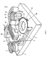
- Fig. 2 shows a first specific embodiment of an inventive device.
- 1 again denotes a central unit and 7 and 8 designate two analytical units.
- the central unit 1 has a separation unit 3, which the reaction vessels by means of a vibrating hopper in a defined position brings.
- a defined amount of sample is introduced into the one reaction vessel which is at the very front, ie immediately before the transfer unit 13.
- the reaction vessel is transferred to the transport unit 6 and transferred to one of the analytical units 7 or 8.
- a sampling unit 30 which is designed as a pipetting device and which takes the predefined amount of sample from the sample vessels.
- the sampling unit 30 or the pipetting needle must be cleaned so that no contamination of the subsequent samples with sample portions from previously processed samples can take place.
- a cleaning unit in Fig. 2 not shown
- a cleaning unit is provided, which is equipped for example of a plurality of rinsing devices for rinsing the pipetting needle. So that the pipetting needle can reach the various positions, the pipetting needle is attached to a swivel arm, which can be swiveled by means of a drive.
- the central unit 1 is further equipped with a measuring device 5 for performing ISE measurements.
- a measuring device 5 for performing ISE measurements.
- the reagents are taken from the reagent vessels 33 and also transferred to the measuring device 5 via the supply opening 34.
- a rinsing process is initiated within the measuring device 5, so that a new measurement can be carried out as a result.
- the analytical units 7 and 8 are constructed identically.
- a circular reaction vessel holder 32 which is supported by a rotating drive unit (in FIG Fig. 2 not shown) is rotatable, and a likewise circular reagent vessel holder 31, which can also be rotated by a drive unit, provided, wherein two transfer units 40, 41 are provided for positioning a respective reaction vessel, each under a reagent vessel, so that an intended amount of reagent from the Reagent can be dispensed into the reaction vessel.
- the transfer units 40, 41 are additionally used as mixers in order to mix the sample with the reagents supplied thereto.
- the reagent vessels 20 to 23 have a circular segment-like cross-section for optimal utilization in the circular reagent vessel holder 31 and are formed on the underside with a nozzle for dispensing a precisely metered amount of reagents as a self-dispensing means.
- the self-dispensing agent and the reagent vessel can, for example, according to the in the international application with the application number PCT / CH 2004/000316 be realized manner described. For this reason the whole revelation content of the PCT / CH 2004/000316 declared as an integral part of the present application.
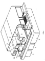
- Fig. 3 shows a second specific embodiment of the inventive device.
- the embodiment according to Fig. 3 from a central unit 1 and a single analytical unit 7.
- the outer peripheries of the two holders 31 and 32 which are shown only partially, overlap such that reagents from one of the reagent vessels can be dispensed into a reaction vessel.
- the reagent vessel holder 31 is arranged above the reaction vessel holder 32.
- the central unit 1 consists essentially of the same components as the central unit according to Fig. 2 , The two variants differ only in the different arrangement of the components and the now apparent cleaning unit 42, in which the pipetting needle of the sampling unit 30 can be cleaned.
- the cleaning unit 42 is provided in the central unit 1 adjacent to one side of the analytical unit 7, and the measuring device 5 is arranged on the opposite side, although this is not mandatory.
- 33 denotes a reagent container holder in which the reagents required in the measuring device 5 are contained.
- the sampling unit 30 with swivel arm and this driving drive unit, which is furthermore arranged centrally in the central unit 1, has good access to the samples in the sample vessels, to the reaction vessels originating from the singling unit 3 and to the cleaning unit 42.
- Fig. 3 The samples can be transferred in two different sized sample holder of the central unit 1.
- the analytical unit 7 again has a circular reaction vessel holder 32 and a reagent vessel holder 31 overlying this, in which the circular segment-shaped reagent vessels 20 to 22 are held, wherein Fig. 3 the reagent vessel holder 31 and the associated reagent vessels in the overlapping region of the holders 31 and 32 are not shown, so that the other units lying in the overlapping area are visible.
- the other units are first of all mixing units 35 and 36, a reading unit 50 which is used, for example, for reading a bar code on a reagent vessel or a reaction vessel, and measuring units 36 to 39, the latter also being arranged outside the overlapping area could be.
- the mixing units 35 and 36 are used for mixing the samples in the reaction vessels, wherein the mixing units 35 and 36 are activated in particular after addition of reagents.
- the mixing units 35 and 36 are also preferably used before performing a measurement in one of the measuring units 36 to 39.
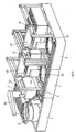
- Fig. 4 shows a third specific embodiment of the inventive device, which in turn is shown in a perspective view with partially cut cover. It can be seen a central unit 1 in combination with two analytical units 7 and 8. The sample vessels are in cassettes fed to the central unit 1, wherein in each case five sample vessels are contained in a cassette. The cassettes are inserted on one side in the central unit 1. For sampling, a sampling unit (in Fig. 4 not shown) containing the predetermined amount of sample either in the measuring device or in a reaction vessel.
- the analytical units 7 and 8 are, unlike those in the embodiments according to Fig. 2 and 3 , not with a circular but with a stationary, rectangular reagent container holder 31 equipped. If a reagent is to be placed in a reaction vessel, it is placed under the nozzle of the corresponding reagent vessel with a ⁇ -R positioning unit. Thereafter, the reaction vessel is optionally conducted in the same way to a measuring unit.
- Fig. 5 a fourth embodiment of the inventive device, again in a perspective view.
- the pipetting device 43 is realized as an XY positioning unit, which removes a required reagent from a reagent vessel and delivers it into a reaction vessel.
- the pipetting needle must be cleaned between the individual pipetting procedures be so that a reagent is not contaminated by another reagent that still adheres to the pipetting needle from the previous pipetting. For this reason, a needle cleaning unit 44 is provided, with which the pipetting needle cleans between the pipetting operations.
- temperature control units are provided in the analytical units in order to set the temperature of the reagents in the reagent vessels and / or the temperature of the samples in the reaction vessels to predetermined values.
- the reagent container holder and / or the reaction vessel holder are largely enclosed in such a way that heat inflows or heat outflows are prevented as far as possible.
- one temperature control unit acts only on the reagent vessels, another temperature control unit only on the reaction vessels, wherein the reagent vessels are kept at a temperature of about 10 ° Celsius and the reaction vessels are maintained at a temperature of about 37 ° Celsius, for example.
- sample pretreatment units can be contained in at least one or all analytical units, in which, for example, the separation of a cellular portion of the sample or an extraction, a separation and / or a purification of certain sample components is undertaken becomes.
- sample pretreatments are necessary, for example, in immunological, molecular or clinical-chemical analyzes.
- the sample pretreatment unit is preferably arranged directly at the transfer location of a reaction vessel to an analytical unit.
Landscapes
- Physics & Mathematics (AREA)
- Health & Medical Sciences (AREA)
- Life Sciences & Earth Sciences (AREA)
- Chemical & Material Sciences (AREA)
- Analytical Chemistry (AREA)
- Biochemistry (AREA)
- General Health & Medical Sciences (AREA)
- General Physics & Mathematics (AREA)
- Immunology (AREA)
- Pathology (AREA)
- Automatic Analysis And Handling Materials Therefor (AREA)
- Analysing Materials By The Use Of Radiation (AREA)
Abstract
Description
Die vorliegende Erfindung betrifft eine Vorrichtung zum Analysieren von Proben.The present invention relates to a device for analyzing samples.
Automatische Probenanalysegeräte, mit denen beispielsweise eine Quantifizierung der Konzentration einer in einer flüssigen Probe aufgelösten Substanz oder die Analyse von Komponenten biologischer Flüssigkeiten, Wasser oder dergleichen durchgeführt werden, sind bekannt. So ist beispielsweise in der deutschen Patentschrift mit der Veröffentlichungsnummer
Analysegeräte mit modularem Aufbau sind im Stand der Technik bekannt. Aus den schriften
Der vorliegenden Erfindung liegt daher die Aufgabe zugrunde, eine Vorrichtung zum Analysieren von Proben anzugeben, die die vorstehend genannten Nachteile nicht aufweist.The present invention is therefore based on the object of specifying a device for analyzing samples which does not have the aforementioned disadvantages.
Diese Aufgabe wird durch die im kennzeichnenden Teil von Anspruch 1 aufgeführten Merkmale gelöst. Vorteilhafte Ausgestaltungen der Erfindung sind in weiteren abhängigen Ansprüchen angegeben.This object is achieved by the features listed in the characterizing part of
Die Erfindung weist die folgenden Vorteile auf: Indem eine Zentraleinheit mit Reaktionsgefässen, eine Transporteinheit zum Transportieren der Reaktionsgefässe und mindestens eine analytische Einheit vorgesehen sind, indem des Weiteren die Zentraleinheit eine Probenentnahmeeinheit enthält, mit der zumindest ein Teil der Probe aus einem Probengefäss in ein Reaktionsgefäss überführt wird, indem ferner zumindest ein Teil der Reaktionsgefässe über die Transporteinheit an mindestens eine der analytischen Einheiten übertragbar ist, indem mindestens ein Reagenzbehälter mit mindestens einem Reagenz vorgesehen ist, das zur Probe im Reaktionsgefäss für eine Reaktion zwischen der Probe und dem Reagenz zuführbar ist, und indem schliesslich mindestens eine Messvorrichtung oder mindestens eine Messeinheit zum Messen einer physikalischen Eigenschaft der Probe vorgesehen ist, wird eine Analyseeinheit geschaffen, die äusserst effizient arbeitet, dabei einen minimalen Ressourcenaufwand benötigt. Von besonderem Vorteil ist dabei der modulare Aufbau der Analyseeinheit, der einen Ausbau der Analysekapazität nach Bedarf ermöglicht. Der modulare Aufbau resultiert zudem in einer einfacheren Wartung der gesamten Analyseeinheit, können doch defekte Einheiten einfach durch neue ersetzt werden.The invention has the following advantages: in that a central unit with reaction vessels, a transport unit for transporting the reaction vessels and at least one analytical unit are provided, in that the central unit also contains a sampling unit, with which at least a portion of the sample from a sample vessel into a reaction vessel In addition, at least part of the reaction vessels can be transferred via the transport unit to at least one of the analytical units by providing at least one reagent container with at least one reagent that can be supplied to the sample in the reaction vessel for a reaction between the sample and the reagent, and by finally providing at least one measuring device or at least one measuring unit for measuring a physical property of the sample, an analysis unit is created which operates extremely efficiently, while using a minimal amount of resources ötigt. Of particular advantage is the modular design of the analysis unit, which allows an expansion of the analysis capacity as needed. The modular design also results in easier maintenance of the entire analysis unit, as defective units can simply be replaced by new ones.
Die vorliegende Erfindung wird im Folgenden anhand von Ausführungsbeispielen, welche in Zeichnungen dargestellt sind, weiter erläutert. Dabei zeigen:
- Fig. 1,
- in schematischer Darstellung, ein Blockschaltbild der erfindungsgemässen Vorrichtung zum Analysieren von Proben,
- Fig. 2
- eine erste konkrete Ausführungsform der erfindungsgemässen Vorrichtung in perspektivischer Darstellung,
- Fig. 3
- eine zweite konkrete Ausführungsform der erfindungsgemässen Vorrichtung in perspektivischer Darstellung,
- Fig. 4
- eine dritte konkrete Ausführungsform der erfindungsgemässen Vorrichtung in perspektivischer Darstellung und
- Fig. 5
- eine vierte konkrete Ausführungsform der erfindungsgemässen Vorrichtung in perspektivischer Darstellung.
- Fig. 1,
- in a schematic representation, a block diagram of the device according to the invention for analyzing samples,
- Fig. 2
- a first specific embodiment of the inventive device in perspective,
- Fig. 3
- a second concrete embodiment of the inventive device in perspective view,
- Fig. 4
- a third specific embodiment of the inventive device in a perspective view and
- Fig. 5
- a fourth specific embodiment of the inventive device in a perspective view.
- Förderband;
- Schüttelstrecke;
- Führungsschienen mit Mitnahmeriemen.
- Conveyor belt;
- Schüttelstrecke;
- Guide rails with carrying strap.
Je nach Destination der Reaktionsgefässe werden diese mit Hilfe von Entnahmevorrichtungen 14 bis 16 von der Transporteinheit 6 übernommen und in die jeweilige analytische Einheit 7, 8 oder 9 eingeschleust, in der die Reaktionsgefässe für eine Analyse vorbereitet werden. Die Vorbereitung besteht zum Beispiel darin, dass ein oder mehrere Reagenzien zur Auslösung einer Reaktion in das jeweilige Reaktionsgefäss eingebracht wird, oder es wird, um ein weiteres Beispiel zu nennen, die Probe im Reaktionsgefäss auf eine vorgegebene Temperatur erwärmt. Im Anschluss an diese vorbereitenden Massnahmen werden die physikalischen und/oder chemischen Eigenschaften während oder nach einer im jeweiligen Reaktionsgefäss stattfindenden Reaktion gemessen, wozu in der analytischen Einheit 7, 8 oder 9 eine oder mehrere Messeinheiten (in
- optische Eigenschaften, wie Absorption;
- Trübung (Turbidimetrie);
- Absorptionsspektrum in einem bestimmten Wellenlängenbereich;
- sekundäre Fluoreszenzemission;
- Polarisation der Fluoreszenzemission.
- optical properties, such as absorption;
- Turbidity (turbidimetry);
- Absorption spectrum in a certain wavelength range;
- secondary fluorescence emission;
- Polarization of fluorescence emission.
Wie aus dem schematischen Blockschaltbild gemäss
Zur Steuerung der erfindungsgemässen Vorrichtung ist zum Beispiel in der Zentraleinheit 1 eine Kontrolleinheit (in
In einer weiteren Ausführungsform der erfindungsgemässen Vorrichtung ist es vorgesehen, die Reaktionsgefässe mit einem Label zur eindeutigen Identifikation zu versehen, das mit einer Identifikationseinheit maschinell gelesen werden kann. Die Identifikationseinheiten werden an notwendigen Positionen in der Zentraleinheit als auch in der bzw. den analytischen Einheiten eingesetzt. In der Kontrolleinheit werden die durch die Identifikationseinheiten eingelesenen Daten mit weiteren Informationen - wie Probeninhalt, verabreichte Reagenzien, durchzuführende Messung, usw. - in einer Datenbank in Beziehung gebracht. Zur Identifikation bzw. maschinellen Einlesen der Daten eignet sich beispielsweise eine der folgenden Techniken:
- ein- oder mehrdimensionale Strichcode;
- andere optische Verfahren;
- Transponder;
- Markierungsmoleküle in der Flüssigkeit.
- one- or multi-dimensional barcode;
- other optical methods;
- transponder;
- Labeling molecules in the liquid.
Die einmal verwendeten Reaktionsgefässe können nach einer gründlichen Reinigung wiederum verwendet werden. Es hat sich jedoch gezeigt, dass eine einmalige Verwendung der Reaktionsgefässe einen geringeren Ressourcenbedarf (z.B. Reinigungsmittel, Wasser, etc.) zur Folge hat. In einer bevorzugten Ausführungsform der erfindungsgemässen Vorrichtung werden daher so genannte Einwegreaktionsgefässe eingesetzt. Damit wird der Aufbau der erfindungsgemässen Vorrichtung vereinfacht. So sind keine Reinigungsvorgänge in den analytischen Einheiten erforderlich. Die Reinigungsvorgänge in der Zentraleinheit sind reduziert auf die Reinigung der Probenentnahmeeinheit, mit der eine bestimmte Probenmenge einem Probengefäss entnommen wird und in ein Reaktionsgefäss abgefüllt wird und daher zwischen den Probenentnahmen gereinigt werden muss, um eine Kontamination durch Übertragung von einer Probe auf eine andere zu vermeiden. Daraus folgt, dass die analytischen Einheiten keine Reinigungsvorrichtungen benötigen und damit insbesondere nicht mit Wasser versorgt werden müssen. Somit muss lediglich die Zentraleinheit 1 mit einem Wasseranschluss versehen sein.The once used reaction vessels can be used again after a thorough cleaning. However, it has been shown that a single use of the reaction vessels has a lower resource requirement (eg detergent, water, etc.) result. In a preferred embodiment of the device according to the invention therefore so-called one-way reaction vessels are used. Thus, the structure of the inventive Device simplified. Thus, no purification operations in the analytical units are required. The cleaning operations in the central unit are reduced to the cleaning of the sampling unit, with a certain amount of sample is taken from a sample vessel and filled into a reaction vessel and therefore must be cleaned between sampling to avoid contamination by transfer from one sample to another , It follows that the analytical units do not require cleaning devices and thus in particular do not need to be supplied with water. Thus, only the
In einer weiteren Ausführungsform der vorliegenden Erfindung ist vorgesehen, dass die Transporteinheit 6 die Reaktionsgefässe nicht nur in einer Richtung transportiert, sondern die Reaktionsgefässe nach Abschluss einer Analyse zurück zur Zentraleinheit 1 transportiert werden. Bei einer solchen Ausführungsform ist anstelle der Vereinzelungseinheit 3 eine Reinigungsstation vorzusehen, in der die Reaktionsgefässe gereinigt werden und für eine erneute Verwendung vorbereitet werden.In a further embodiment of the present invention, it is provided that the
Das Abfüllen der definierten Probenmenge in das Reaktionsgefäss erfolgt mit Hilfe einer Probenentnahmeeinheit 30, die als Pipettiervorrichtung ausgebildet ist und die aus den Probengefässen die vordefinierte Probenmenge entnimmt. Zwischen den einzelnen Probenentnahmen muss die Probenentnahmeeinheit 30 bzw. die Pipettiernadel gereinigt werden, damit keine Kontamination der nachfolgenden Proben mit Probenanteilen aus früher verarbeiteten Proben erfolgen kann. Für die Reinigung ist eine Reinigungseinheit (in
Die Zentraleinheit 1 ist des Weiteren mit einer Messvorrichtung 5 zur Durchführung von ISE-Messungen ausgestattet. Hierzu wird nicht etwa ein Reaktionsgefäss mit Hilfe der Probenentnahmeeinheit 30 mit einer vorgegebenen Probenmenge abgefüllt und der Messvorrichtung 5 übergeben, sondern es wird die vorbestimmte Probenmenge direkt der Messvorrichtung 5 mit Hilfe der Probenentnahmeeinheit 30 über eine Zufuhröffnung 34 zugeführt. Nach Bedarf der durchzuführenden Messung werden Reagenzien den Reagenzgefässen 33 entnommen und ebenfalls über die Zufuhröffnung 34 der Messvorrichtung 5 übergeben. Nach Abschluss der Messungen in der Messvorrichtung 5 wird innerhalb der Messvorrichtung 5 ein Spülvorgang eingeleitet, damit in der Folge eine neue Messung durchgeführt werden kann.The
Die analytischen Einheiten 7 und 8 sind identisch aufgebaut. Neben der durch die analytischen Einheiten 7 und 8 führenden Transporteinheit 6 sind ein kreisförmiger Reaktionsgefässhalter 32, welcher durch eine rotierende Antriebseinheit (in
Denkbar sind auch Ausführungsvarianten, bei denen lediglich eine Transfereinheit oder bei denen mehr als zwei Transfereinheiten zur Positionierung von Reaktionsgefässen vorgesehen sind. Darüber hinaus sind auch Varianten vorgesehen, bei denen die Reagenzgefässe anstelle der Reaktionsgefässe durch Transfereinheiten positioniert werden, oder es werden sowohl die Reaktionsgefässe als auch die Reagenzgefässe positioniert.Also conceivable are embodiments in which only one transfer unit or in which more than two transfer units are provided for the positioning of reaction vessels. In addition, variants are also provided in which the reagent vessels are positioned by transfer units instead of the reaction vessels, or both the reaction vessels and the reagent vessels are positioned.
Die Reagenzgefässe 20 bis 23 weisen zur optimalen Ausnützung im kreisförmigen Reagenzgefässhalter 31 einen kreissegmentartigen Querschnitt auf und sind auf der Unterseite mit einer Düse zur Abgabe einer exakt dosierbaren Menge an Reagenzien als selbst dispensierendes Mittel ausgebildet. Die selbst dispensierenden Mittel als auch das Reagenzgefäss können beispielsweise gemäss der in der internationalen Anmeldung mit der Anmeldenummer
Es wird ausdrücklich darauf hingewiesen, dass die selbst dispensierenden Mittel im vorstehend genannten Sinne bei allen beschriebenen Ausführungsvarianten zum Einsatz kommen können.It is expressly pointed out that the self-dispensing means in the above sense can be used in all described embodiments variants.
Die Zentraleinheit 1 besteht im Wesentlichen aus den gleichen Komponenten wie die Zentraleinheit gemäss
Gemäss
So können Probenhalter mit fünf und mit fünfzehn Proben der Zentraleinheit 1 übergeben werden.Thus sample holders with five and with fifteen samples of the
Die analytische Einheit 7 weist wiederum einen kreisförmigen Reaktionsgefässhalter 32 und einen diesen überlagernden Reagenzgefässhalter 31 auf, in dem die kreissegmentförmigen Reagenzgefässe 20 bis 22 gehalten werden, wobei in
Die analytischen Einheiten 7 und 8 sind, im Unterschied zu denjenigen in den Ausführungsvarianten gemäss
Schliesslich zeigt
Bei allen beschriebenen Ausführungsvarianten der erfindungsgemässen Vorrichtung ist es denkbar, dass in den analytischen Einheiten Temperiereinheiten vorgesehen sind, um die Temperatur der Reagenzien in den Reagenzgefässen und/oder die Temperatur der Proben in den Reaktionsgefässen auf vorbestimmte Werte einzustellen. Hierzu werden die Reagenzgefässhalter und/oder die Reaktionsgefässhalter weitestgehend so eingefasst, dass Wärmezuflüsse oder Wärmeabflüsse möglichst verhindert werden. Mithin wirkt zum Beispiel die eine Temperiereinheit lediglich auf die Reagenzgefässe, eine weitere Temperiereinheit lediglich auf die Reaktionsgefässe, wobei die Reagenzgefässe beispielsweise auf einer Temperatur von ca. 10° Celsius und die Reaktionsgefässe beispielsweise auf einer Temperatur von ca. 37° Celsius gehalten werden.In all described embodiments of the device according to the invention, it is conceivable that temperature control units are provided in the analytical units in order to set the temperature of the reagents in the reagent vessels and / or the temperature of the samples in the reaction vessels to predetermined values. For this purpose, the reagent container holder and / or the reaction vessel holder are largely enclosed in such a way that heat inflows or heat outflows are prevented as far as possible. Thus, for example, one temperature control unit acts only on the reagent vessels, another temperature control unit only on the reaction vessels, wherein the reagent vessels are kept at a temperature of about 10 ° Celsius and the reaction vessels are maintained at a temperature of about 37 ° Celsius, for example.
In gleicher Weise können bei allen beschriebenen Ausführungsvarianten in mindestens einer oder in allen analytischen Einheiten so genannte Probenvorbehandlungseinheiten enthalten sein, in denen beispielsweise die Abtrennung eines zellulären Anteils der Probe oder eine Extraktion, eine Separation und/oder eine Purifikation von gewissen Probenbestandteilen vorgenommen wird. Solche Probenvorbehandlungen sind zum Beispiel bei immunologischen, molekularen oder klinisch-chemische Analysen notwendig. Die Probenvorbehandlungseinheit ist vorzugsweise unmittelbar am Übergabeort eines Reaktionsgefässes an eine analytische Einheit angeordnet.In the same way, in all described embodiments, so-called sample pretreatment units can be contained in at least one or all analytical units, in which, for example, the separation of a cellular portion of the sample or an extraction, a separation and / or a purification of certain sample components is undertaken becomes. Such sample pretreatments are necessary, for example, in immunological, molecular or clinical-chemical analyzes. The sample pretreatment unit is preferably arranged directly at the transfer location of a reaction vessel to an analytical unit.
Claims (18)
- Device for analyzing samples, which are supplied in sample vessels (2), characterized in that a central unit (1) with reaction vessels, a transport unit (6) for the transporting of the reaction vessels and at least one analytical unit (7,8,9) are provided, that the central unit (1) includes a sampling unit (30), by which at least a part of the sample is transferred from a sample vessel (2) into a reaction vessel, that at least a part of the reaction vessels is transferable to at least one of the analytical units (7,8,9) via the transport unit (6), that at least one reagent vessel (20,...,23) with at least one reagent is provided in the analytical unit (7,8,9), which reagent is supplied to the sample in the reaction vessel for a reaction between the sample and the reagent, whereby those reagents are provided in the analytical unit (7,8,9) which are supplied to the samples for measuring physical properties, and that at least one measuring device (5) or at least one measuring unit (37,38,39) for the measuring of a physical property of the sample is provided in said analytical unit (7,8,9).
- Device according to claim 1, characterized in that the measuring device (5) is included in the central unit (1).
- Device according to claim 2, characterized in that an ion-selective-electrolyte measurement is performable in the measuring device (5), the reagents required therefore being provided in the central unit (1).
- Device according to one of the preceding claims, characterized in that those reagents are provided in the analytical unit (7,8,9) which are supplied to the samples for measuring a physical property, for which determination the measuring unit (37,38,39) is usable.
- Device according to one of the preceding claims, characterized in that the reagents are provided in single reagent vessels (20,...,23), or in cassettes with at least one reagent vessel.
- Device according to claim 5, characterized in that the cassettes have self dispensing means for the dispensing of reagents, a self dispensing means being provided for each reagent vessel.
- Device according to one of the preceding claims, characterized in that the reaction vessels are of the type one way reaction vessel.
- Device according to one of the preceding claims, characterized in that the transport unit (6) transports the reaction vessels only in one direction, namely from the central unit (1) to one of the analytical units (7,8,9).
- Device according to one of the preceding claims, characterized in that a separation unit (3) is provided in the central unit (1), in which separation unit the reaction vessels are provided.
- Device according to one of the preceding claims, characterized in that the reaction vessels and/or reagent vessels are identifiable, whereby for the identification one or more of the following technologies are being used:- one- or more dimensional bar codes;- other optical methods;- transponder;- marking molecules in the liquid.
- Device according to claim 10, characterized in that identification units for the identification of the reaction vessels and/or the reagent vessels are provided in the analytical units (7,8,9).
- Device according to one of the preceding claims, characterized in that the analytical units (7,8,9) have heating units for adjusting a temperature of the reagents.
- Device according to one of the preceding claims, characterized in that the analytical units (7,8,9) have further heating units for adjusting a temperature of the samples contained in the reaction vessels.
- Device according to one of the preceding claims, characterized in that only the central unit (1) is supplied with water.
- Device according to one of the preceding claims, characterized in that the at least one analytical unit (7,8,9) has a mixing unit (35,36) for the mixing of the sample with the supplied reagents.
- Device according to one of the preceding claims, characterized in that a cleaning unit (42) for cleaning the sampling unit (30) is provided in the central unit (1).
- Device according to one of the preceding claims, characterized in that the sampling unit (30) is a pipette unit.
- Device according to one of the preceding claims, characterized in that a sample pre-treatment unit is included in the central unit (1) and/or in the at least one analytical unit (7,8,9).
Priority Applications (11)
| Application Number | Priority Date | Filing Date | Title |
|---|---|---|---|
| DE502004006789T DE502004006789D1 (en) | 2004-11-25 | 2004-11-25 | Device for analyzing samples |
| AT04027974T ATE391918T1 (en) | 2004-11-25 | 2004-11-25 | DEVICE FOR ANALYZING SAMPLES |
| ES04027974T ES2303014T3 (en) | 2004-11-25 | 2004-11-25 | DEVICE FOR THE SAMPLE ANALYSIS. |
| EP04027974A EP1662261B1 (en) | 2004-11-25 | 2004-11-25 | Device for analysis of samples |
| PCT/CH2005/000625 WO2006056083A1 (en) | 2004-11-25 | 2005-10-25 | Device for analyzing samples |
| JP2007541625A JP5506155B2 (en) | 2004-11-25 | 2005-10-25 | Sample analyzer |
| US11/791,495 US8003050B2 (en) | 2004-11-25 | 2005-10-25 | Device for analyzing samples |
| CN2005800403209A CN101065670B (en) | 2004-11-25 | 2005-10-25 | Device for analyzing samples |
| CA2580442A CA2580442C (en) | 2004-11-25 | 2005-10-25 | Device for analyzing samples |
| HK08101308.7A HK1112507A1 (en) | 2004-11-25 | 2008-02-04 | Device for analyzing samples |
| US13/179,780 US8178043B2 (en) | 2004-11-25 | 2011-07-11 | Device for analyzing samples |
Applications Claiming Priority (1)
| Application Number | Priority Date | Filing Date | Title |
|---|---|---|---|
| EP04027974A EP1662261B1 (en) | 2004-11-25 | 2004-11-25 | Device for analysis of samples |
Publications (2)
| Publication Number | Publication Date |
|---|---|
| EP1662261A1 EP1662261A1 (en) | 2006-05-31 |
| EP1662261B1 true EP1662261B1 (en) | 2008-04-09 |
Family
ID=34927525
Family Applications (1)
| Application Number | Title | Priority Date | Filing Date |
|---|---|---|---|
| EP04027974A Revoked EP1662261B1 (en) | 2004-11-25 | 2004-11-25 | Device for analysis of samples |
Country Status (10)
| Country | Link |
|---|---|
| US (2) | US8003050B2 (en) |
| EP (1) | EP1662261B1 (en) |
| JP (1) | JP5506155B2 (en) |
| CN (1) | CN101065670B (en) |
| AT (1) | ATE391918T1 (en) |
| CA (1) | CA2580442C (en) |
| DE (1) | DE502004006789D1 (en) |
| ES (1) | ES2303014T3 (en) |
| HK (1) | HK1112507A1 (en) |
| WO (1) | WO2006056083A1 (en) |
Families Citing this family (28)
| Publication number | Priority date | Publication date | Assignee | Title |
|---|---|---|---|---|
| EP1662261B1 (en) * | 2004-11-25 | 2008-04-09 | Roche Diagnostics GmbH | Device for analysis of samples |
| DE102005061640B4 (en) * | 2005-12-22 | 2009-05-14 | Btg Instruments Gmbh | Device for analyzing a sample liquid |
| JP4980671B2 (en) * | 2006-08-18 | 2012-07-18 | シスメックス株式会社 | Blood sample analyzer |
| JPWO2009031455A1 (en) * | 2007-09-03 | 2010-12-16 | ベックマン・コールター・インコーポレーテッド | Automatic analyzer |
| DE102008030330B4 (en) * | 2008-06-30 | 2011-12-08 | Andreas Hettich Gmbh & Co. Kg | Device for feeding sample containers with an analysis sample to be treated to a treatment device |
| DE102008058062A1 (en) * | 2008-11-18 | 2010-05-20 | Diasys Diagnostic Systems Gmbh | Automated analyzer with a revolving carousel for various liquid containers |
| JP5452507B2 (en) * | 2009-01-29 | 2014-03-26 | 株式会社日立ハイテクノロジーズ | Automatic analyzer |
| WO2011034169A1 (en) * | 2009-09-18 | 2011-03-24 | 日立化成工業株式会社 | Automatic analyzing device |
| EP2322939A1 (en) | 2009-11-16 | 2011-05-18 | BIT Analytical Instruments GmbH | Analysis system and analysis method |
| US8728395B2 (en) * | 2010-01-28 | 2014-05-20 | Hitachi High-Technologies Corporation | Automatic analyzer |
| JP5340975B2 (en) * | 2010-01-29 | 2013-11-13 | 株式会社日立ハイテクノロジーズ | Automatic analyzer |
| JP5608399B2 (en) * | 2010-03-26 | 2014-10-15 | シスメックス株式会社 | Sample processing system |
| EP2538225A1 (en) | 2011-06-20 | 2012-12-26 | F. Hoffmann-La Roche AG | System for processing closed sample tubes |
| JP5789441B2 (en) * | 2011-08-01 | 2015-10-07 | 株式会社日立ハイテクノロジーズ | Genetic testing system |
| JP5982764B2 (en) * | 2011-09-21 | 2016-08-31 | 東ソー株式会社 | Automatic analyzer |
| JP5830330B2 (en) * | 2011-09-27 | 2015-12-09 | シスメックス株式会社 | Sample analyzer |
| WO2013056415A1 (en) * | 2011-10-18 | 2013-04-25 | 长沙高新技术产业开发区爱威科技实业有限公司 | Automatic detection control device for sample tangible ingredient analyzer and control method thereof |
| JP5877058B2 (en) * | 2011-12-22 | 2016-03-02 | シスメックス株式会社 | Sample processing equipment |
| EP2972402B1 (en) | 2013-03-15 | 2023-12-20 | Abbott Laboratories | Diagnostic analyzers with pretreatment carousels and related methods |
| JP6169245B2 (en) | 2013-03-15 | 2017-07-26 | アボット・ラボラトリーズAbbott Laboratories | Automatic diagnostic analyzer with rear accessible truck system and related method |
| CN109358202B (en) | 2013-03-15 | 2023-04-07 | 雅培制药有限公司 | Automated diagnostic analyzer with vertically arranged carousel and related methods |
| JP6515677B2 (en) * | 2014-07-24 | 2019-05-22 | ソニー株式会社 | Contact structure and electrical measurement apparatus for biological sample using the contact structure |
| ES2829802T3 (en) | 2015-01-23 | 2021-06-02 | Hoffmann La Roche | Loading device for loading a reagent turntable of an analytical instrument with reagent containers and analytical instrument |
| JP2019506619A (en) * | 2015-12-18 | 2019-03-07 | アボット ラボラトリーズ | System and method for automated analysis |
| AU2017220028B2 (en) | 2016-02-17 | 2022-04-28 | Becton, Dickinson And Company | Automated sample preparation system for diagnostic testing of same |
| WO2017184244A1 (en) | 2016-04-22 | 2017-10-26 | Becton. Dickinson And Company | Automated diagnostic analyzer and method for its operation |
| EP3446132B1 (en) | 2016-04-22 | 2023-06-14 | Becton, Dickinson and Company | Automated analyzer piercing stoppers for aspiration |
| CN110208554B (en) * | 2019-06-06 | 2021-05-11 | 深圳传世生物医疗有限公司 | Sample analysis system, control method thereof and sample analysis method |
Family Cites Families (44)
| Publication number | Priority date | Publication date | Assignee | Title |
|---|---|---|---|---|
| US4066412A (en) * | 1966-04-26 | 1978-01-03 | E. I. Du Pont De Nemours And Company | Automatic clinical analyzer |
| CH568793A5 (en) * | 1974-02-15 | 1975-11-14 | Mettler Instrumente Ag | |
| GB1595296A (en) * | 1976-12-03 | 1981-08-12 | Nat Res Dev | Automation of discrete analysis systems |
| JPS55136958A (en) | 1979-04-14 | 1980-10-25 | Olympus Optical Co Ltd | Automatic analyzer |
| JPS56132548A (en) | 1980-03-21 | 1981-10-16 | Olympus Optical Co Ltd | Automatic analyzer |
| ES275136Y (en) * | 1981-07-20 | 1984-10-01 | American Hospital Supply Corporation | ANCHORING DEVICE FOR PELDANS IN CONCRETE PIECES OR SIMILAR. |
| US4818493A (en) * | 1985-10-31 | 1989-04-04 | Bio/Data Corporation | Apparatus for receiving a test specimen and reagent |
| US4849340A (en) | 1987-04-03 | 1989-07-18 | Cardiovascular Diagnostics, Inc. | Reaction system element and method for performing prothrombin time assay |
| JP2569611B2 (en) | 1987-10-26 | 1997-01-08 | 三菱瓦斯化学株式会社 | Rice increase agent |
| JPH03156372A (en) * | 1989-08-30 | 1991-07-04 | Shimadzu Corp | Automatic analyser and automatic container feed apparatus |
| FR2655151B1 (en) * | 1989-11-24 | 1992-04-03 | Chateau Guy | AUTOMATIC INSTALLATION OF IMMUNOLOGICAL OR BIOCHEMICAL ANALYSIS USING MICROTITRATION Cuvettes. |
| GB9020352D0 (en) | 1990-09-18 | 1990-10-31 | Anagen Ltd | Assay or reaction apparatus |
| JPH06265559A (en) * | 1993-03-12 | 1994-09-22 | Eisai Co Ltd | Automatic immunoanalyzer |
| JPH07833A (en) * | 1993-06-14 | 1995-01-06 | Bio Mach:Kk | Insertion of chip for micropipet into rack |
| JP3031237B2 (en) * | 1996-04-10 | 2000-04-10 | 株式会社日立製作所 | Method of transporting sample rack and automatic analyzer for transporting sample rack |
| WO1998018009A1 (en) * | 1996-10-23 | 1998-04-30 | Hitachi, Ltd. | Biochemical analyzer |
| WO1999046281A2 (en) | 1998-03-10 | 1999-09-16 | Genentech, Inc. | Novel polypeptides and nucleic acids encoding the same |
| JP3906781B2 (en) * | 1997-04-09 | 2007-04-18 | 株式会社日立製作所 | Specimen analysis system and method of handling the same |
| JP3582316B2 (en) * | 1997-08-20 | 2004-10-27 | 株式会社日立製作所 | Chemical analyzer |
| DE69840189D1 (en) * | 1997-09-11 | 2008-12-18 | Hitachi Ltd | Sample handling system for automatic analyzers |
| US6141602A (en) * | 1997-09-25 | 2000-10-31 | Hitachi, Ltd. | Specimen processing system |
| DE19849591C2 (en) | 1997-10-27 | 2001-07-19 | Hitachi Ltd | Automatic analyzer |
| JP3460543B2 (en) * | 1997-10-27 | 2003-10-27 | 株式会社日立製作所 | Automatic analyzer |
| AUPP058197A0 (en) * | 1997-11-27 | 1997-12-18 | A.I. Scientific Pty Ltd | Pathology sample tube distributor |
| US6337050B1 (en) * | 1998-04-20 | 2002-01-08 | Hitachi, Ltd. | Sample rack handling system |
| DE69942220D1 (en) * | 1998-07-27 | 2010-05-20 | Hitachi Ltd | Method for handling body fluid samples and analyzer. which uses these |
| JP3930977B2 (en) * | 1998-07-31 | 2007-06-13 | 株式会社日立製作所 | Sample processing system |
| DE19835071A1 (en) * | 1998-08-04 | 2000-02-10 | Zeiss Carl Jena Gmbh | Transport system for handling microtiter plates |
| US6649128B1 (en) * | 1998-09-23 | 2003-11-18 | Randox Laboratories Ltd | Assay device processing instrument |
| EP0994355A1 (en) * | 1998-09-23 | 2000-04-19 | Randox Laboratories Ltd. | Assay device processing instrument |
| EP1305638B1 (en) * | 2000-07-21 | 2010-12-15 | Beckman Coulter, Inc. | Workstation for integrating automated chemical analyzers |
| JP2002048800A (en) * | 2000-07-31 | 2002-02-15 | Olympus Optical Co Ltd | Automatic analyzer |
| WO2002037078A2 (en) | 2000-10-31 | 2002-05-10 | Dpc Cirrus, Inc. | Automated immunoassay analyzer and method of using the same |
| JP2002181835A (en) * | 2000-12-15 | 2002-06-26 | Hitachi Ltd | Specimen treatment system |
| US6790412B2 (en) * | 2001-02-06 | 2004-09-14 | Beckman Coulter, Inc. | Bulk vessel feeder |
| US6825041B2 (en) * | 2001-03-16 | 2004-11-30 | Beckman Coulter, Inc. | Method and system for automated immunochemistry analysis |
| US7250303B2 (en) * | 2001-07-20 | 2007-07-31 | Ortho-Clinical Diagnostics, Inc. | Chemistry system for a clinical analyzer |
| JP2003083958A (en) * | 2001-09-11 | 2003-03-19 | Jun Kikuchi | Blood analyzer and blood analyzing method |
| JP2004271265A (en) * | 2003-03-06 | 2004-09-30 | Hitachi High-Technologies Corp | Automatic analyzer |
| US7185288B2 (en) * | 2003-07-18 | 2007-02-27 | Dade Behring Inc. | Operator interface module segmented by function in an automatic clinical analyzer |
| ATE400817T1 (en) * | 2004-03-31 | 2008-07-15 | Hoffmann La Roche | MODULAR ANALYZING DEVICE |
| EP1662261B1 (en) * | 2004-11-25 | 2008-04-09 | Roche Diagnostics GmbH | Device for analysis of samples |
| JP4336360B2 (en) * | 2006-09-20 | 2009-09-30 | 株式会社アイディエス | Sample pretreatment transport device |
| US7950940B2 (en) | 2008-02-25 | 2011-05-31 | Cooper Technologies Company | Separable connector with reduced surface contact |
-
2004
- 2004-11-25 EP EP04027974A patent/EP1662261B1/en not_active Revoked
- 2004-11-25 AT AT04027974T patent/ATE391918T1/en active
- 2004-11-25 ES ES04027974T patent/ES2303014T3/en active Active
- 2004-11-25 DE DE502004006789T patent/DE502004006789D1/en active Active
-
2005
- 2005-10-25 CN CN2005800403209A patent/CN101065670B/en not_active Expired - Fee Related
- 2005-10-25 CA CA2580442A patent/CA2580442C/en not_active Expired - Fee Related
- 2005-10-25 JP JP2007541625A patent/JP5506155B2/en not_active Expired - Fee Related
- 2005-10-25 WO PCT/CH2005/000625 patent/WO2006056083A1/en active Application Filing
- 2005-10-25 US US11/791,495 patent/US8003050B2/en not_active Expired - Fee Related
-
2008
- 2008-02-04 HK HK08101308.7A patent/HK1112507A1/en not_active IP Right Cessation
-
2011
- 2011-07-11 US US13/179,780 patent/US8178043B2/en active Active
Also Published As
| Publication number | Publication date |
|---|---|
| WO2006056083A1 (en) | 2006-06-01 |
| US20110262303A1 (en) | 2011-10-27 |
| ES2303014T3 (en) | 2008-08-01 |
| CA2580442A1 (en) | 2006-06-01 |
| US8178043B2 (en) | 2012-05-15 |
| US20080003137A1 (en) | 2008-01-03 |
| HK1112507A1 (en) | 2008-09-05 |
| US8003050B2 (en) | 2011-08-23 |
| CN101065670B (en) | 2012-11-07 |
| JP2008522138A (en) | 2008-06-26 |
| CA2580442C (en) | 2012-12-04 |
| ATE391918T1 (en) | 2008-04-15 |
| JP5506155B2 (en) | 2014-05-28 |
| DE502004006789D1 (en) | 2008-05-21 |
| EP1662261A1 (en) | 2006-05-31 |
| CN101065670A (en) | 2007-10-31 |
Similar Documents
| Publication | Publication Date | Title |
|---|---|---|
| EP1662261B1 (en) | Device for analysis of samples | |
| DE69735176T2 (en) | Analyzer for multiple analyzes with multiple test modules | |
| DE3115600C2 (en) | Method and device for the automatic analysis of chemical substances in liquid samples | |
| EP0043079B1 (en) | Automatic analysis apparatus | |
| DE60207499T2 (en) | Transfer unit as well as this containing automatic analysis device | |
| DE69835181T2 (en) | Automatic sample analysis system and method of operation | |
| EP0937983B1 (en) | Automatic analyser | |
| EP0520304B1 (en) | Analyser for the automatic analysis of body fluids | |
| DE69834754T2 (en) | Sample Analysis System | |
| DE60224757T2 (en) | Additional delivery system for samples in a clinical analyzer | |
| DE4109118C2 (en) | Method for the automatic evaluation of a sample component of a water sample | |
| DE2755264C3 (en) | Chemical analysis facility | |
| DE112010001896B4 (en) | Automatic analyzer | |
| DE3014250A1 (en) | AUTOMATIC ANALYZER FOR LIQUID SAMPLES | |
| WO2003040697A1 (en) | Method and devices for the cross-referencing of identification of object supports for microtomised analytical samples and for the generation of said identification | |
| EP2502082B1 (en) | Analysis system and analysis method | |
| WO2018077352A1 (en) | Apparatus and method for handling samples containing biological cells | |
| EP2492015B1 (en) | Sample container, system and analysis method | |
| EP3216517B1 (en) | Method for mixing a liquid in an automatic analyzer | |
| DE3908123C2 (en) | ||
| DE2607055A1 (en) | Fluid sample analyser for soil extracts - has three conveyors carrying soil vessels to flame and spectral photometers and pH meter | |
| EP3220147B1 (en) | Warning system for potentially faulty measurement results in an automatic analyzer | |
| DE2341158A1 (en) | AUTOMATIC ANALYZER, IN PARTICULAR FOR CLINICAL AND PHARMACEUTICAL PURPOSES | |
| EP3550308A1 (en) | Laboratory analysis system with improved sample pipetting | |
| EP3418749B1 (en) | Optical monitoring of mixing operations |
Legal Events
| Date | Code | Title | Description |
|---|---|---|---|
| PUAI | Public reference made under article 153(3) epc to a published international application that has entered the european phase |
Free format text: ORIGINAL CODE: 0009012 |
|
| 17P | Request for examination filed |
Effective date: 20041125 |
|
| AK | Designated contracting states |
Kind code of ref document: A1 Designated state(s): AT BE BG CH CY CZ DE DK EE ES FI FR GB GR HU IE IS IT LI LU MC NL PL PT RO SE SI SK TR |
|
| AX | Request for extension of the european patent |
Extension state: AL HR LT LV MK YU |
|
| AKX | Designation fees paid |
Designated state(s): AT BE BG CH CY CZ DE DK EE ES FI FR GB GR HU IE IS IT LI LU MC NL PL PT RO SE SI SK TR |
|
| 17Q | First examination report despatched |
Effective date: 20070124 |
|
| RIN1 | Information on inventor provided before grant (corrected) |
Inventor name: SCHWERZMANN, LEO Inventor name: BURKHARDT, CLAUDIUS Inventor name: JUCH, MATHIAS Inventor name: SCHACHER, GOTTLIEB |
|
| GRAP | Despatch of communication of intention to grant a patent |
Free format text: ORIGINAL CODE: EPIDOSNIGR1 |
|
| GRAS | Grant fee paid |
Free format text: ORIGINAL CODE: EPIDOSNIGR3 |
|
| GRAA | (expected) grant |
Free format text: ORIGINAL CODE: 0009210 |
|
| STAA | Information on the status of an ep patent application or granted ep patent |
Free format text: STATUS: THE PATENT HAS BEEN GRANTED |
|
| AK | Designated contracting states |
Kind code of ref document: B1 Designated state(s): AT BE BG CH CY CZ DE DK EE ES FI FR GB GR HU IE IS IT LI LU MC NL PL PT RO SE SI SK TR |
|
| REG | Reference to a national code |
Ref country code: GB Ref legal event code: FG4D Free format text: NOT ENGLISH |
|
| REG | Reference to a national code |
Ref country code: CH Ref legal event code: EP |
|
| REG | Reference to a national code |
Ref country code: IE Ref legal event code: FG4D Free format text: LANGUAGE OF EP DOCUMENT: GERMAN |
|
| REF | Corresponds to: |
Ref document number: 502004006789 Country of ref document: DE Date of ref document: 20080521 Kind code of ref document: P |
|
| REG | Reference to a national code |
Ref country code: CH Ref legal event code: NV Representative=s name: TROESCH SCHEIDEGGER WERNER AG |
|
| REG | Reference to a national code |
Ref country code: ES Ref legal event code: FG2A Ref document number: 2303014 Country of ref document: ES Kind code of ref document: T3 |
|
| PG25 | Lapsed in a contracting state [announced via postgrant information from national office to epo] |
Ref country code: SI Free format text: LAPSE BECAUSE OF FAILURE TO SUBMIT A TRANSLATION OF THE DESCRIPTION OR TO PAY THE FEE WITHIN THE PRESCRIBED TIME-LIMIT Effective date: 20080409 |
|
| NLV1 | Nl: lapsed or annulled due to failure to fulfill the requirements of art. 29p and 29m of the patents act | ||
| PG25 | Lapsed in a contracting state [announced via postgrant information from national office to epo] |
Ref country code: PT Free format text: LAPSE BECAUSE OF FAILURE TO SUBMIT A TRANSLATION OF THE DESCRIPTION OR TO PAY THE FEE WITHIN THE PRESCRIBED TIME-LIMIT Effective date: 20080910 Ref country code: FI Free format text: LAPSE BECAUSE OF FAILURE TO SUBMIT A TRANSLATION OF THE DESCRIPTION OR TO PAY THE FEE WITHIN THE PRESCRIBED TIME-LIMIT Effective date: 20080409 Ref country code: BG Free format text: LAPSE BECAUSE OF FAILURE TO SUBMIT A TRANSLATION OF THE DESCRIPTION OR TO PAY THE FEE WITHIN THE PRESCRIBED TIME-LIMIT Effective date: 20080709 Ref country code: NL Free format text: LAPSE BECAUSE OF FAILURE TO SUBMIT A TRANSLATION OF THE DESCRIPTION OR TO PAY THE FEE WITHIN THE PRESCRIBED TIME-LIMIT Effective date: 20080409 |
|
| ET | Fr: translation filed | ||
| PG25 | Lapsed in a contracting state [announced via postgrant information from national office to epo] |
Ref country code: PL Free format text: LAPSE BECAUSE OF FAILURE TO SUBMIT A TRANSLATION OF THE DESCRIPTION OR TO PAY THE FEE WITHIN THE PRESCRIBED TIME-LIMIT Effective date: 20080409 |
|
| REG | Reference to a national code |
Ref country code: IE Ref legal event code: FD4D |
|
| PG25 | Lapsed in a contracting state [announced via postgrant information from national office to epo] |
Ref country code: IS Free format text: LAPSE BECAUSE OF FAILURE TO SUBMIT A TRANSLATION OF THE DESCRIPTION OR TO PAY THE FEE WITHIN THE PRESCRIBED TIME-LIMIT Effective date: 20080809 |
|
| PLBI | Opposition filed |
Free format text: ORIGINAL CODE: 0009260 |
|
| PG25 | Lapsed in a contracting state [announced via postgrant information from national office to epo] |
Ref country code: DK Free format text: LAPSE BECAUSE OF FAILURE TO SUBMIT A TRANSLATION OF THE DESCRIPTION OR TO PAY THE FEE WITHIN THE PRESCRIBED TIME-LIMIT Effective date: 20080409 Ref country code: CZ Free format text: LAPSE BECAUSE OF FAILURE TO SUBMIT A TRANSLATION OF THE DESCRIPTION OR TO PAY THE FEE WITHIN THE PRESCRIBED TIME-LIMIT Effective date: 20080409 Ref country code: IE Free format text: LAPSE BECAUSE OF FAILURE TO SUBMIT A TRANSLATION OF THE DESCRIPTION OR TO PAY THE FEE WITHIN THE PRESCRIBED TIME-LIMIT Effective date: 20080409 Ref country code: SE Free format text: LAPSE BECAUSE OF FAILURE TO SUBMIT A TRANSLATION OF THE DESCRIPTION OR TO PAY THE FEE WITHIN THE PRESCRIBED TIME-LIMIT Effective date: 20080709 |
|
| PLAF | Information modified related to communication of a notice of opposition and request to file observations + time limit |
Free format text: ORIGINAL CODE: EPIDOSCOBS2 |
|
| PLAX | Notice of opposition and request to file observation + time limit sent |
Free format text: ORIGINAL CODE: EPIDOSNOBS2 |
|
| 26 | Opposition filed |
Opponent name: INSTRUMENTATION LABORATORY COMPANY Effective date: 20090109 Opponent name: QIAGEN GMBH Effective date: 20090108 |
|
| PG25 | Lapsed in a contracting state [announced via postgrant information from national office to epo] |
Ref country code: SK Free format text: LAPSE BECAUSE OF FAILURE TO SUBMIT A TRANSLATION OF THE DESCRIPTION OR TO PAY THE FEE WITHIN THE PRESCRIBED TIME-LIMIT Effective date: 20080409 Ref country code: RO Free format text: LAPSE BECAUSE OF FAILURE TO SUBMIT A TRANSLATION OF THE DESCRIPTION OR TO PAY THE FEE WITHIN THE PRESCRIBED TIME-LIMIT Effective date: 20080409 |
|
| PG25 | Lapsed in a contracting state [announced via postgrant information from national office to epo] |
Ref country code: EE Free format text: LAPSE BECAUSE OF FAILURE TO SUBMIT A TRANSLATION OF THE DESCRIPTION OR TO PAY THE FEE WITHIN THE PRESCRIBED TIME-LIMIT Effective date: 20080409 |
|
| BERE | Be: lapsed |
Owner name: F. HOFFMANN-LA ROCHE A.G. Effective date: 20081130 Owner name: ROCHE DIAGNOSTICS G.M.B.H. Effective date: 20081130 |
|
| PLAF | Information modified related to communication of a notice of opposition and request to file observations + time limit |
Free format text: ORIGINAL CODE: EPIDOSCOBS2 |
|
| PG25 | Lapsed in a contracting state [announced via postgrant information from national office to epo] |
Ref country code: MC Free format text: LAPSE BECAUSE OF NON-PAYMENT OF DUE FEES Effective date: 20081130 |
|
| PLBB | Reply of patent proprietor to notice(s) of opposition received |
Free format text: ORIGINAL CODE: EPIDOSNOBS3 |
|
| PG25 | Lapsed in a contracting state [announced via postgrant information from national office to epo] |
Ref country code: CY Free format text: LAPSE BECAUSE OF FAILURE TO SUBMIT A TRANSLATION OF THE DESCRIPTION OR TO PAY THE FEE WITHIN THE PRESCRIBED TIME-LIMIT Effective date: 20080409 Ref country code: BE Free format text: LAPSE BECAUSE OF NON-PAYMENT OF DUE FEES Effective date: 20081130 |
|
| PG25 | Lapsed in a contracting state [announced via postgrant information from national office to epo] |
Ref country code: LU Free format text: LAPSE BECAUSE OF NON-PAYMENT OF DUE FEES Effective date: 20081125 Ref country code: HU Free format text: LAPSE BECAUSE OF FAILURE TO SUBMIT A TRANSLATION OF THE DESCRIPTION OR TO PAY THE FEE WITHIN THE PRESCRIBED TIME-LIMIT Effective date: 20081010 |
|
| PG25 | Lapsed in a contracting state [announced via postgrant information from national office to epo] |
Ref country code: TR Free format text: LAPSE BECAUSE OF FAILURE TO SUBMIT A TRANSLATION OF THE DESCRIPTION OR TO PAY THE FEE WITHIN THE PRESCRIBED TIME-LIMIT Effective date: 20080409 |
|
| PG25 | Lapsed in a contracting state [announced via postgrant information from national office to epo] |
Ref country code: GR Free format text: LAPSE BECAUSE OF FAILURE TO SUBMIT A TRANSLATION OF THE DESCRIPTION OR TO PAY THE FEE WITHIN THE PRESCRIBED TIME-LIMIT Effective date: 20080710 |
|
| PLAB | Opposition data, opponent's data or that of the opponent's representative modified |
Free format text: ORIGINAL CODE: 0009299OPPO |
|
| R26 | Opposition filed (corrected) |
Opponent name: QIAGEN GMBH Effective date: 20090108 |
|
| PLAY | Examination report in opposition despatched + time limit |
Free format text: ORIGINAL CODE: EPIDOSNORE2 |
|
| PLBC | Reply to examination report in opposition received |
Free format text: ORIGINAL CODE: EPIDOSNORE3 |
|
| PLAB | Opposition data, opponent's data or that of the opponent's representative modified |
Free format text: ORIGINAL CODE: 0009299OPPO |
|
| R26 | Opposition filed (corrected) |
Opponent name: QIAGEN GMBH Effective date: 20090108 |
|
| REG | Reference to a national code |
Ref country code: FR Ref legal event code: PLFP Year of fee payment: 12 |
|
| REG | Reference to a national code |
Ref country code: FR Ref legal event code: PLFP Year of fee payment: 13 |
|
| APAH | Appeal reference modified |
Free format text: ORIGINAL CODE: EPIDOSCREFNO |
|
| APBM | Appeal reference recorded |
Free format text: ORIGINAL CODE: EPIDOSNREFNO |
|
| APBP | Date of receipt of notice of appeal recorded |
Free format text: ORIGINAL CODE: EPIDOSNNOA2O |
|
| APBQ | Date of receipt of statement of grounds of appeal recorded |
Free format text: ORIGINAL CODE: EPIDOSNNOA3O |
|
| REG | Reference to a national code |
Ref country code: FR Ref legal event code: PLFP Year of fee payment: 14 |
|
| REG | Reference to a national code |
Ref country code: FR Ref legal event code: PLFP Year of fee payment: 15 |
|
| PGFP | Annual fee paid to national office [announced via postgrant information from national office to epo] |
Ref country code: CH Payment date: 20201015 Year of fee payment: 17 Ref country code: IT Payment date: 20201117 Year of fee payment: 17 Ref country code: AT Payment date: 20201027 Year of fee payment: 17 Ref country code: ES Payment date: 20201202 Year of fee payment: 17 Ref country code: DE Payment date: 20201013 Year of fee payment: 17 Ref country code: GB Payment date: 20201029 Year of fee payment: 17 Ref country code: FR Payment date: 20201023 Year of fee payment: 17 |
|
| APBU | Appeal procedure closed |
Free format text: ORIGINAL CODE: EPIDOSNNOA9O |
|
| REG | Reference to a national code |
Ref country code: DE Ref legal event code: R064 Ref document number: 502004006789 Country of ref document: DE Ref country code: DE Ref legal event code: R103 Ref document number: 502004006789 Country of ref document: DE |
|
| RDAF | Communication despatched that patent is revoked |
Free format text: ORIGINAL CODE: EPIDOSNREV1 |
|
| STAA | Information on the status of an ep patent application or granted ep patent |
Free format text: STATUS: PATENT REVOKED |
|
| RDAG | Patent revoked |
Free format text: ORIGINAL CODE: 0009271 |
|
| STAA | Information on the status of an ep patent application or granted ep patent |
Free format text: STATUS: PATENT REVOKED |
|
| REG | Reference to a national code |
Ref country code: CH Ref legal event code: PL |
|
| 27W | Patent revoked |
Effective date: 20210326 |
|
| GBPR | Gb: patent revoked under art. 102 of the ep convention designating the uk as contracting state |
Effective date: 20210326 |
|
| REG | Reference to a national code |
Ref country code: FI Ref legal event code: MGE |
|
| REG | Reference to a national code |
Ref country code: AT Ref legal event code: MM01 Ref document number: 391918 Country of ref document: AT Kind code of ref document: T Effective date: 20211125 |