EP1661683B1 - Process and device for compression moulding plastics - Google Patents
Process and device for compression moulding plastics Download PDFInfo
- Publication number
- EP1661683B1 EP1661683B1 EP06000562A EP06000562A EP1661683B1 EP 1661683 B1 EP1661683 B1 EP 1661683B1 EP 06000562 A EP06000562 A EP 06000562A EP 06000562 A EP06000562 A EP 06000562A EP 1661683 B1 EP1661683 B1 EP 1661683B1
- Authority
- EP
- European Patent Office
- Prior art keywords
- holder
- compression moulding
- elements
- compression molding
- pellet
- Prior art date
- Legal status (The legal status is an assumption and is not a legal conclusion. Google has not performed a legal analysis and makes no representation as to the accuracy of the status listed.)
- Expired - Lifetime
Links
Images

Classifications
-
- B—PERFORMING OPERATIONS; TRANSPORTING
- B29—WORKING OF PLASTICS; WORKING OF SUBSTANCES IN A PLASTIC STATE IN GENERAL
- B29C—SHAPING OR JOINING OF PLASTICS; SHAPING OF MATERIAL IN A PLASTIC STATE, NOT OTHERWISE PROVIDED FOR; AFTER-TREATMENT OF THE SHAPED PRODUCTS, e.g. REPAIRING
- B29C43/00—Compression moulding, i.e. applying external pressure to flow the moulding material; Apparatus therefor
- B29C43/32—Component parts, details or accessories; Auxiliary operations
- B29C43/34—Feeding the material to the mould or the compression means
-
- B—PERFORMING OPERATIONS; TRANSPORTING
- B29—WORKING OF PLASTICS; WORKING OF SUBSTANCES IN A PLASTIC STATE IN GENERAL
- B29C—SHAPING OR JOINING OF PLASTICS; SHAPING OF MATERIAL IN A PLASTIC STATE, NOT OTHERWISE PROVIDED FOR; AFTER-TREATMENT OF THE SHAPED PRODUCTS, e.g. REPAIRING
- B29C43/00—Compression moulding, i.e. applying external pressure to flow the moulding material; Apparatus therefor
- B29C43/32—Component parts, details or accessories; Auxiliary operations
- B29C43/52—Heating or cooling
-
- B—PERFORMING OPERATIONS; TRANSPORTING
- B29—WORKING OF PLASTICS; WORKING OF SUBSTANCES IN A PLASTIC STATE IN GENERAL
- B29C—SHAPING OR JOINING OF PLASTICS; SHAPING OF MATERIAL IN A PLASTIC STATE, NOT OTHERWISE PROVIDED FOR; AFTER-TREATMENT OF THE SHAPED PRODUCTS, e.g. REPAIRING
- B29C43/00—Compression moulding, i.e. applying external pressure to flow the moulding material; Apparatus therefor
- B29C43/32—Component parts, details or accessories; Auxiliary operations
- B29C43/34—Feeding the material to the mould or the compression means
- B29C2043/3405—Feeding the material to the mould or the compression means using carrying means
- B29C2043/3411—Feeding the material to the mould or the compression means using carrying means mounted onto arms, e.g. grippers, fingers, clamping frame, suction means
-
- B—PERFORMING OPERATIONS; TRANSPORTING
- B29—WORKING OF PLASTICS; WORKING OF SUBSTANCES IN A PLASTIC STATE IN GENERAL
- B29C—SHAPING OR JOINING OF PLASTICS; SHAPING OF MATERIAL IN A PLASTIC STATE, NOT OTHERWISE PROVIDED FOR; AFTER-TREATMENT OF THE SHAPED PRODUCTS, e.g. REPAIRING
- B29C43/00—Compression moulding, i.e. applying external pressure to flow the moulding material; Apparatus therefor
- B29C43/32—Component parts, details or accessories; Auxiliary operations
- B29C43/50—Removing moulded articles
- B29C2043/503—Removing moulded articles using ejector pins, rods
-
- B—PERFORMING OPERATIONS; TRANSPORTING
- B29—WORKING OF PLASTICS; WORKING OF SUBSTANCES IN A PLASTIC STATE IN GENERAL
- B29C—SHAPING OR JOINING OF PLASTICS; SHAPING OF MATERIAL IN A PLASTIC STATE, NOT OTHERWISE PROVIDED FOR; AFTER-TREATMENT OF THE SHAPED PRODUCTS, e.g. REPAIRING
- B29C31/00—Handling, e.g. feeding of the material to be shaped, storage of plastics material before moulding; Automation, i.e. automated handling lines in plastics processing plants, e.g. using manipulators or robots
- B29C31/04—Feeding of the material to be moulded, e.g. into a mould cavity
- B29C31/042—Feeding of the material to be moulded, e.g. into a mould cavity using dispensing heads, e.g. extruders, placed over or apart from the moulds
- B29C31/048—Feeding of the material to be moulded, e.g. into a mould cavity using dispensing heads, e.g. extruders, placed over or apart from the moulds the material being severed at the dispensing head exit, e.g. as ring, drop or gob, and transported immediately into the mould, e.g. by gravity
Definitions
- the invention relates to a method for molding thermoplastic between two compression molding elements and a device thereto.
- Compression molding is a long-known means, in particular to produce articles made of a thermoplastic material.
- closures are made for food packaging, especially plastic closures for beverage bottles.
- the raw granules are extruded and the desired amount is cut off, which is deposited on a part of a compression molding tool. Subsequently, a second molding tool penetrates into the first molding tool so that the desired product is molded.
- thermoplastic material is dispensed as an annular blank in an extruder.
- a molding die is arranged, the inner shape of which corresponds to the outer shape of the tube head to be produced.
- the intermediate carrier has a coaxially extendable rod, which protrudes beyond the surface and on the one hand centered the blank with an annular cross-section and on the other hand keeps the discharge opening for the tube head during pressing free.
- the EP 0 728 064 B shows a method for molding a tube made of plastic tube to a tube tube.
- the lenticular blank is deposited on the auxiliary carrier.
- a mold pin is arranged centrally on the subcarrier and displaceable in the auxiliary carrier and in the subcarrier bar during the molding process against axial spring pressure.
- the mold comprises a forming part which is formed by a part of the end surface of the subcarrier, the inner contour, the mold jaws and the shoulder mold space.
- a recess in a serving for the guidance of the subcarrier with the subcarrier rod Insert is designed such that the subcarrier can be accommodated in the lowest position and then the end face forms the mold bottom.
- the US 3,795,473 (FA Automation System Design & Construction) describes a machine for the production of brake shoes and brake linings. This includes a plurality of hot presses on a first turntable and additional assemblies for feeding preformed pellets to the hot presses. On a second turntable, a press for producing the pellets and adjacent thereto a brake pad composition metering device may be arranged. The pellets produced are transported by means of a pivoting pliers from the second turntable to the hot presses on the first turntable.
- the hot presses comprise a master cylinder, a pilot cylinder and a plurality of heating plates and mold elements. After inserting a pellet, the corresponding press with the turntable is rotated by one position, so that the next press is positioned at the transfer point.
- the US 5,863,571 (Sidel) concerns a machine for the production of containers, such as As bottles or pots, by heat treatment and blow molding of plastic preforms.
- the machine comprises at least two forming tools arranged on a turntable.
- Each mold comprises at least two cavities and thus enables the production of twice the number of small containers on a machine designed for the production of larger containers.
- devices for adjusting the cadence are provided in the following.
- To feed the preforms in the cavities of the molds serve transfer elements, which comprise an arm with a holding device with clamps. The arm is rotatable about a pivot axis.
- Corresponding devices are also provided for removing the blow-molded container by a further device.
- the object of the invention is to provide a method and a structurally simple device, which allow the production of closures, in particular of an extruded plastic raw material without an uncontrolled surface structure occurs at the closures.
- a portion of raw material is deposited on a holder with a small contact surface.
- the raw mass on the bearing surface has a distance from a molding press element and is delivered to the molding elements only immediately before or at the beginning of the pressing.
- the holder is pliers-shaped and arranged on a side wall of one of the compression molding elements.
- the extruded portion of the plastic - also called pellet - has a temperature of about 180 ° Celsius.
- the compression molding elements have an operating temperature which is about 120 ° to 150 ° lower.
- the portion of the extruded plastic mass is deposited on the first compression molding element, it is not completely in the inventive method on this, but only on the small contact surface of the holder.
- the "cold shock" at the contact surface to the holder is so small that the existing in the prior art effects are largely avoided. Only immediately before or at the beginning of pressing is the pellet in contact with the compression molding elements.
- the pliers parts open and the pellet falls, preferably precisely positioned on one of the compression molding elements.
- the holder is completely retracted or swung away to the side so that the other compression molding element can penetrate into the one compression molding element.
- the pincer-shaped holder protrudes from the side into the first compression molding element.
- the holder may also consist of several parts, which are arranged on the circumference of the compression molding element.
- the pellet is centered by the holder.
- the centering of the pellet is done on the one hand by an approximately accurate deposition of the pellet on the holder and on the other hand by the design of the support surface of the holder.
- a uniform distribution of mass usually affects the quality of production. In asymmetric molds, the centering is obsolete, unless a specific (centric or eccentric) position is desired.
- the device according to the invention comprises a first compression molding element with a holder and a second compression molding element which penetrates into the first compression molding element in such a way that a pellet - a portion of extruded, thermoplastic plastic material - is compression molded between these two compression molding elements.
- the holder has a small bearing surface for the pellet and supports it before it comes into contact with the first compression molding.
- the bearing surface must be designed accordingly. If the pellet has a consistency which hardly allows the pellet to flow, the support surface can be made smaller than if the pellet tends to flow.
- a timed moving of the holder is preferred.
- Such control is tuned to the power stroke of the entire manufacturing device.
- the holder lowers as soon as the second compression molding element penetrates into the first compression molding element.
- the known systems offer.
- the control of the holder is cam-controlled, the holder is reciprocated by a mechanism which extends along a preferably curved rail or along a predetermined curved path.
- the second compression molding element is preferably also cam-controlled in such a case.
- the two controllers can also be combined into one controller. For entertaining reasons, however, two coordinated but mechanically largely independent controls for the holder and the compression molding elements are preferred.
- the holder can for example also be pressure-controlled.
- a sensor measures the pressure on the holder. As soon as the second molding element touches the pellet and thus the pressure on the holder increases, it is withdrawn and releases the pellet for the molding process.
- the control can also be pneumatic or hydraulic.
- the device and thus the compression molding elements are in particular designed for molding plastic closures, as they are used for beverage bottles.
- the first compression molding element is preferably arranged at the bottom, serves as a so-called die and receives the holder.
- the second compression molding element is designed as a punch and penetrates into the first compression molding element.
- a so-called turret is used for the production of molded products, which has a controlled rotating working platform, which is equipped with a plurality of inventive devices.
- Each of the arranged devices has its own control, which are matched to the controls of the other devices. This allows high processing speeds and high precision.
- the control of the individual parts, in particular of the holder, the landfill device and the second compression molding elements is preferably timed.
- the control is essentially cam-controlled, which leads to an optimal movement sequence of the production. Under cam controlled is a time-controlled motion, which is controlled by a predetermined curve.
- the individual movements can be controlled with a shared curve.
- each individual movement sequence is controlled by separate curves, which are coordinated with one another.
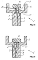
- FIG. 1 is a schematic, perspective sectional view of a compression molding member shown with a holder.
- the holder is not according to the invention, but the illustrated device and the following description are helpful in understanding the invention.
- the first molding tool 1 is arranged at the bottom, for which reason the second molding tool 14 penetrates from above into the first molding tool 1.
- the names above and below refer to the drawing shown.
- the first molding tool 1 could also be arranged at the top, which would require penetration of the second molding tool 14 from below into the first molding tool 1.
- the first molding tool 1 consists of a die 2 and a base 3.
- the die 2 is a hollow cylinder 4 with a bottom 5.
- the die 2 is the negative mold, which the exterior design of the plastic closure 16 determined.
- the thickness of the bottom 5 of the die 2 is approximately equal to the thickness of the hollow cylinder 4 is formed.
- the base 3 is monolithically connected to the die 2. In the illustrated device, the base 3 is formed as a cylinder. The dimensions depend on the product to be manufactured and the associated loads.
- a bore is arranged in the axial direction, in which a plunger 6 in the vertical direction (see arrow 11) can be moved back and forth.
- a sliding layer is provided, for example, a Teflon coating to substantially eliminate the friction of the plunger 6 with the base 3.
- a recess 7 is arranged in the imaginary dividing line between the lower edge of the bottom 5 and the upper edge of the base 3.
- the holder 8 consists on the one hand of a base plate 9 and three pins 10 which are fixed to the base plate 9.
- the base plate 9 is connected to the plunger 6 such that reciprocating movements of the plunger 6 are simulated simultaneously by the base plate 9.
- the bottom 5 has according to the thickness and the number of pins 10 holes formed so that the pins 10 can penetrate the bottom 5.
- the arrangement of the pins 10 as a "tripod" is exemplary, depending on the application, the number may range from one to a number of pins required according to the application.
- the holder is pulled back in the vertical direction or in this illustration. Since the recess 7 has to accommodate the holder 8 to a large extent, the height of the recess 7 is exactly or slightly more than the thickness of the base plate 9 and the length of the pins 10 minus the thickness of the bottom 5. Further details will become apparent in the following embodiment Part of the individual process steps.
- FIGS. 2a-c show individual steps of a method for molding thermoplastic by means of schematic sections.
- the holder used is not according to the invention, but the following description of the method is helpful in understanding the invention.
- FIG. 2a shows the starting position of the first compression molding tool 1, in which the holder 8 is raised to the stop of the base plate 9.
- the first molding tool 1 is cooled down to about 17 ° Celsius with a water cycle (not shown here).
- the pins 10 of the holder 8 penetrate the holes in the bottom 5 and project beyond it so far that a sufficiently large distance from the support points of the holder 8 to the bottom 5 of the compression molding element 1 is present. This ensures that the portion of extruded thermoplastic material deposited on this holder 8, referred to hereinafter as the pellet 12, does not cool down too much.
- This, although between the pellet 12 and the first molding tool 1 is a large temperature difference - in this example, about 160 ° Celsius.
- the preparation of the plastic is carried out by a known per se extrusion. As soon as a holder 8 is located under an extruder opening, a pellet 12 is cut off at this, in the working range of the turret reaching into the extruder and deposited on the pins 10 of the holder 8, or deposited. Each opening of the extruder is controlled to open and close. The process from landfill to actual compression takes about two seconds. Since the pellet 12 has only a small contact area with the substantially colder holder 8 and the residence time of the pellet 12 on this relatively short, there is no strong cooling of the pellet 12 and its temperature, which is about 180 ° C, remains until largely preserved for the actual compression molding.
- the compression molding takes place, as in Figure 2c is shown.
- the time during which the pellet is on Thus, for example, it is only 1/5 or less of the time that the pellet is from landfill to effective (described below) compression within the mold.
- the second molding tool 14 which was preheated with a water cycle (not shown here) to a temperature of about 50 ° Celsius, penetrates into the first, cooled molding tool 1.
- the punch 15 of the second compression molding tool 14 forms the inner shape, which should have, for example, the plastic closure 16.
- the temperature data is an embodiment of the preparation.
- the temperatures, in particular of the compression molding tools 1 and 14, can be adapted to the requirements and workflow without this leading to a solution which is outside the scope of the invention.
- the two compression molding tools 1 and 14 remain in the molding position for one to two seconds and cool the molded plastic closure 16. Subsequently, the first molding tool 1 is lowered and preferably pulled the second molding tool upwards. The plastic closure 16 remains adhering to the punch 15 of the second compression molding tool 14. With a sleeve (not shown here), which slides down along the punch 15, the plastic closure 16 is stripped off.
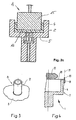
- FIG. 3 A not according to the invention variant of the holder 8 is in FIG. 3 shown.
- a tube 17 is arranged.
- the pellet is deposited on the tube 17 and this is withdrawn according to the previous versions, or sunk in the first compression molding tool.
- the tube wall of the tube 17 is preferably made as thin as possible so that the contact area between the tube 17 and the pellet is kept as small as possible. The rest of the construction of the holder 8 largely corresponds to the previously made statements.
- Fig. 4 shows a schematic representation of a laterally mounted inventive holder 18.
- the holder 18 is rotatably attached, for example, with a bolt 20.
- the holder 18 is preferably formed in two parts in the horizontal plane.
- the holder 18 can open as scissors or forceps and release the pellet 12 in a simple way for the compression molding process. So that the holder 18 is not in the way during the molding process, it is turned off, for example, about the axis of rotation 21, which is formed by the bolt 20 to the side.
- the holder 18 is swung back again.
- the construction may also be modified in that the holder 18 is drawn to the right from the action area of the second molding tool with respect to this illustration.
- the first molding tool with the holder can also be arranged at the top, based on the illustration.
- the pellet must adhere to the holder until the second molding tool is in the position that the pellet can not fall next to this second molding tool.
- the holder is designed in the form of a small pliers.
- the pins may have at their reaching into the molding tool end bends, which hold the pellet temporarily, similar to a gripping device.
- the retainer retracts into the first molding die and releases the pellet when it can no longer fall adjacent to the second molding tool.
- the temperatures of, for example, the holder and / or preferably of the molding tools can be adjusted.
- the flow temperatures of the water circuits, which heat the molding tools, or cool are adjusted. This makes it possible to lower the temperature difference between the pellet and the holder or, in particular, the first molding tool, so that the possibility of a "glazing" effect on the finished product is further reduced.
- plastic closures are created by the inventive method and the inventive device, which have no or only a small uncontrolled surface structure, without the production of such plastic closures is slowed down.
Abstract
Description
Die Erfindung betrifft ein Verfahren zum Ausformen von thermoplastischem Kunststoff zwischen zwei Formpresselementen und eine Vorrichtung dazu.The invention relates to a method for molding thermoplastic between two compression molding elements and a device thereto.
Formpressen ist ein seit langem bekanntes Mittel, insbesondere Gegenstände aus einem thermoplastischen Material herzustellen. Beispielsweise werden Verschlüsse für Nahrungsmittel-Verpackungen hergestellt, insbesondere Kunststoffverschlüsse für Getränkeflaschen.Compression molding is a long-known means, in particular to produce articles made of a thermoplastic material. For example, closures are made for food packaging, especially plastic closures for beverage bottles.
Damit der vorzugsweise thermoplastische Kunststoff verarbeitet werden kann, wird das Rohgranulat extrudiert und die gewünschte Menge abgeschnitten, welche auf ein Teil eines Formpresswerkzeugs deponiert wird. Anschliessend dringt ein zweites Formpresswerkzeug in das erste Formpresswerkzeug derart ein, dass das gewünschte Produkt geformt wird.In order for the preferably thermoplastic material to be processed, the raw granules are extruded and the desired amount is cut off, which is deposited on a part of a compression molding tool. Subsequently, a second molding tool penetrates into the first molding tool so that the desired product is molded.
Aus der
Die
Die
Die
Bei den bisher bekannten Verfahren tritt oft eine unkontrollierte Oberflächenstruktur auf, welche insbesondere materialtechnisch und ästhetisch unerwünscht ist. Vor allem bei Verschlüssen von Nahrungsmittelbehältern ist neben den funktionellen Eigenschaften die Ästhetik von wesentlicher Bedeutung.In the previously known methods often occurs on an uncontrolled surface structure, which is particularly undesirable material and aesthetically. Especially with closures of food containers in addition to the functional properties of the Aesthetics essential.
Aufgabe der Erfindung ist es, ein Verfahren und eine konstruktiv einfache Vorrichtung zu schaffen, welche die Herstellung von Verschlüssen erlauben, insbesondere aus einer extrudierten Kunststoff-Rohmasse, ohne dass eine unkontrollierte Oberflächenstruktur an den Verschlüssen auftritt.The object of the invention is to provide a method and a structurally simple device, which allow the production of closures, in particular of an extruded plastic raw material without an uncontrolled surface structure occurs at the closures.
Die Lösung der Aufgabe ist durch die Merkmale des Anspruchs 1 definiert. Gemäss der Erfindung wird bei einem Verfahren zum Ausformen von thermoplastischem Kunststoff zwischen einem ersten und einem zweiten Formpresselement eine Portion Rohmasse auf einem Halter geringer Auflagefläche deponiert. Die Rohmasse auf der Auflagefläche weist einen Abstand zum einen Formpresselement auf und wird erst unmittelbar vor dem, beziehungsweise zu Beginn des Pressens an die Formpresselemente abgegeben. Der Halter ist zangenförmig ausgebildet und an einer Seitenwand eines der Formpresselemente angeordnet.The solution of the problem is defined by the features of claim 1. According to the invention, in a method for molding thermoplastic material between a first and a second molding element, a portion of raw material is deposited on a holder with a small contact surface. The raw mass on the bearing surface has a distance from a molding press element and is delivered to the molding elements only immediately before or at the beginning of the pressing. The holder is pliers-shaped and arranged on a side wall of one of the compression molding elements.
Die extrudierte Portion des Kunststoffs - auch Pellet genannt - weist eine Temperatur von etwa 180° Celsius auf. Die Formpresselemente haben dagegen eine um etwa 120° bis 150° niedrigere Betriebstemperatur. Im Rahmen der Erfindung wurde nun erkannt, dass der Zeitraum zwischen dem Deponieren der Portion und dem Ausformen kritisch für das Entstehen von unerwünschten Oberflächenveränderungen ist. Der zangenförmige Halter weist eine geringe Auflagefläche auf. Durch dessen Einsatz kann deshalb der flächige Kontakt vor dem Formen so kurz wie möglich gehalten werden, so dass "Verglasungseffekte" der Oberfläche vermieden werden können.The extruded portion of the plastic - also called pellet - has a temperature of about 180 ° Celsius. By contrast, the compression molding elements have an operating temperature which is about 120 ° to 150 ° lower. Within the scope of the invention, it has now been recognized that the period between the deposit of the portion and the shaping is critical for the development of undesired surface changes. The pincer-shaped holder has a small contact surface. By its use, therefore, the surface contact can be kept as short as possible before molding, so that "glazing effects" of the surface can be avoided.
Wenn die Portion der extrudierten Kunststoffmasse auf dem ersten Formpresselement deponiert wird, liegt sie bei dem erfindungsgemässen Verfahren nicht vollständig auf diesem auf, sondern nur auf der geringen Auflagefläche des Halters. Dadurch, dass die Kontaktfläche zwischen dem Halter und dem Pellet so klein wie möglich gehalten wird, ist eine zu starke Abkühlung, insbesondere eine starke partielle Abkühlung, der extrudierten Kunststoff-Rohmasse vor dem Formpressvorgang nicht möglich. Der "Kälteschock" an der Kontaktfläche zum Halter ist derart klein, dass die beim Stand der Technik vorhandenen Auswirkungen weitgehend vermieden werden. Erst unmittelbar vor beziehungsweise zu Beginn des Pressens erfolgt der Kontakt des Pellets mit den Formpresselementen.If the portion of the extruded plastic mass is deposited on the first compression molding element, it is not completely in the inventive method on this, but only on the small contact surface of the holder. The fact that the contact surface between the holder and the pellet is kept as small as possible, is a excessive cooling, especially a strong partial cooling, the extruded plastic raw material before the molding process is not possible. The "cold shock" at the contact surface to the holder is so small that the existing in the prior art effects are largely avoided. Only immediately before or at the beginning of pressing is the pellet in contact with the compression molding elements.
Vor oder während dem Formpressvorgang öffnen sich die Zangenteile und das Pellet fällt, vorzugsweise genau positioniert auf eines der Formpresselemente. Sobald das Pellet den Halter verlassen hat, wird der Halter ganz zurückgezogen oder zur Seite derart weggeschwenkt, dass das andere Formpresselement in das eine Formpresselement eindringen kann. Vorzugsweise ragt der zangenförmige Halter von der Seite her in das erste Formpresselement hinein.Before or during the molding process, the pliers parts open and the pellet falls, preferably precisely positioned on one of the compression molding elements. Once the pellet has left the holder, the holder is completely retracted or swung away to the side so that the other compression molding element can penetrate into the one compression molding element. Preferably, the pincer-shaped holder protrudes from the side into the first compression molding element.
Der Halter kann auch aus mehreren Teilen bestehen, welche am Umfang des Formpresselements angeordnet sind.The holder may also consist of several parts, which are arranged on the circumference of the compression molding element.
Es ist vorteilhaft, wenn das Pellet durch den Halter zentriert wird. Die Zentrierung des Pellets erfolgt einerseits durch eine annähernd genaue Deponierung des Pellets auf dem Halter und anderseits durch die Ausgestaltung der Auflagefläche des Halters. Eine gleichmässige Verteilung der Masse wirkt sich in der Regel auf die Qualität der Produktion aus. Bei asymmetrischen Pressformen ist die Zentrierung hinfällig, es sei denn, es wird eine ganz bestimmte (zentrische oder exzentrische) Position angestrebt.It is advantageous if the pellet is centered by the holder. The centering of the pellet is done on the one hand by an approximately accurate deposition of the pellet on the holder and on the other hand by the design of the support surface of the holder. A uniform distribution of mass usually affects the quality of production. In asymmetric molds, the centering is obsolete, unless a specific (centric or eccentric) position is desired.
Die erfindungsgemässe Vorrichtung umfasst ein erstes Formpresselement mit einem Halter und ein zweites Formpresselement, welches in das erste Formpresselement derart eindringt, dass ein Pellet - eine Portion extrudierte, thermoplastische Kunststoffmasse - zwischen diesen beiden Formpresselementen formgepresst wird. Der Halter weist eine geringe Auflagefläche für das Pellet auf und stützt dieses ab, bevor es mit dem ersten Formpresselement in Kontakt kommt.The device according to the invention comprises a first compression molding element with a holder and a second compression molding element which penetrates into the first compression molding element in such a way that a pellet - a portion of extruded, thermoplastic plastic material - is compression molded between these two compression molding elements. The holder has a small bearing surface for the pellet and supports it before it comes into contact with the first compression molding.
Je nach Konsistenz des Pellets muss die Auflagefläche entsprechend ausgebildet sein. Wenn das Pellet eine Konsistenz aufweist, welche das Pellet kaum fliessen lässt, kann die Auflagefläche kleiner ausgebildet werden, als wenn das Pellet eher zum Fliessen neigt.Depending on the consistency of the pellet, the bearing surface must be designed accordingly. If the pellet has a consistency which hardly allows the pellet to flow, the support surface can be made smaller than if the pellet tends to flow.
Auf den Arbeitsablauf bezogen, ist ein zeitlich gesteuertes Bewegen des Halters bevorzugt. Eine solche Steuerung wird auf den Arbeitstakt der gesamten Herstellungsvorrichtung abgestimmt. Vorzugsweise senkt sich der Halter, sobald das zweite Formpresselement in das erste Formpresselement eindringt. Als Art der Steuerung bieten sich die bekannten Systeme an. Wenn die Steuerung des Halters kurvengesteuert erfolgt, wird der Halter über einen Mechanismus hin- und herbewegt, welcher entlang einer vorzugsweise gekrümmten Schiene beziehungsweise entlang einer vorbestimmten Kurvenbahn verläuft. Das zweite Formpresselement wird in einem solchen Fall vorzugsweise auch kurvengesteuert. Dabei können die beiden Steuerungen auch zu einer Steuerung zusammengefasst werden. Aus unterhaltstechnischen Gründen sind jedoch zwei aufeinander abgestimmte, jedoch mechanisch weitgehend unabhängige Steuerungen für den Halter und die Formpresselemente bevorzugt.Based on the workflow, a timed moving of the holder is preferred. Such control is tuned to the power stroke of the entire manufacturing device. Preferably, the holder lowers as soon as the second compression molding element penetrates into the first compression molding element. As a type of control, the known systems offer. When the control of the holder is cam-controlled, the holder is reciprocated by a mechanism which extends along a preferably curved rail or along a predetermined curved path. The second compression molding element is preferably also cam-controlled in such a case. The two controllers can also be combined into one controller. For entertaining reasons, however, two coordinated but mechanically largely independent controls for the holder and the compression molding elements are preferred.
Neben der bevorzugten Kurvensteuerung kann der Halter beispielsweise auch druckgesteuert werden. Dabei misst ein Sensor den Druck auf den Halter. Sobald das zweite Formpresselement das Pellet berührt und somit der Druck auf dem Halter zunimmt, wird dieser zurückgezogen und gibt das Pellet für den Formpressvorgang frei. Die Steuerung kann auch pneumatisch oder hydraulisch erfolgen.In addition to the preferred curve control, the holder can for example also be pressure-controlled. A sensor measures the pressure on the holder. As soon as the second molding element touches the pellet and thus the pressure on the holder increases, it is withdrawn and releases the pellet for the molding process. The control can also be pneumatic or hydraulic.
Die Vorrichtung und somit die Formpresselemente sind insbesondere zum Ausformen von Kunststoffverschlüssen ausgebildet, wie sie für Getränkeflaschen zum Einsatz kommen. Das erste Formpresselement ist vorzugsweise unten angeordnet, dient als sogenannte Matrize und nimmt den Halter auf. Das zweite Formpresselement ist als Stempel ausgebildet und dringt in das erste Formpresselement ein.The device and thus the compression molding elements are in particular designed for molding plastic closures, as they are used for beverage bottles. The first compression molding element is preferably arranged at the bottom, serves as a so-called die and receives the holder. The second compression molding element is designed as a punch and penetrates into the first compression molding element.
Vorzugsweise wird zur Herstellung von formgepressten Produkten ein sogenannter Drehturm verwendet, der eine gesteuert rotierende Arbeitsplattform aufweist, welche mit einer Vielzahl von erfindungsgemässen Vorrichtungen ausgerüstet ist. Jede der angeordneten Vorrichtungen weist eine eigene Steuerung auf, wobei diese mit den Steuerungen der übrigen Vorrichtungen abgestimmt sind. Damit lassen sich hohe Verarbeitungsgeschwindigkeiten bei gleichzeitig hoher Präzision erreichen. Die Steuerung der einzelnen Teile, insbesondere des Halters, der Deponiervorrichtung und der zweiten Formpresselemente erfolgt bevorzugt zeitlich gesteuert. Vorzugsweise ist die Steuerung im Wesentlichen kurvengesteuert, was zu einem optimalen Bewegungsablauf der Produktion führt. Unter kurvengesteuert wird ein zeitlich gesteuerter Bewegungsablauf verstanden, welcher anhand einer vorgegebenen Kurve gesteuert wird. Dabei können die einzelnen Bewegungsabläufe mit einer gemeinsam genutzten Kurve gesteuert werden. Bevorzugt wird jedoch jeder einzelne Bewegungsablauf mit separaten Kurven gesteuert, welche aufeinander abgestimmt sind.Preferably, a so-called turret is used for the production of molded products, which has a controlled rotating working platform, which is equipped with a plurality of inventive devices. Each of the arranged devices has its own control, which are matched to the controls of the other devices. This allows high processing speeds and high precision. The control of the individual parts, in particular of the holder, the landfill device and the second compression molding elements is preferably timed. Preferably, the control is essentially cam-controlled, which leads to an optimal movement sequence of the production. Under cam controlled is a time-controlled motion, which is controlled by a predetermined curve. The individual movements can be controlled with a shared curve. Preferably, however, each individual movement sequence is controlled by separate curves, which are coordinated with one another.
Aus der nachfolgenden Detailbeschreibung und der Gesamtheit der Patentansprüche ergeben sich weitere vorteilhafte Ausführungsformen und Merkmalskombinationen der Erfindung.From the following detailed description and the totality of the claims, further advantageous embodiments and feature combinations of the invention result.
Die zur Erläuterung des Ausführungsbeispiels verwendeten Zeichnungen zeigen:
- Fig. 1
- Eine schematische, perspektivische Schnittdarstellung eines Formpress- elements mit einem Halter;
- Fig. 2a-c
- anhand schematischer Schnitte ein Verfahren zum Ausformen von thermoplastischem Kunststoff;
- Fig. 3
- eine Variante des Halters aus
Figur 1 und - Fig.4
- eine schematische Darstellung eines erfindungsgemässen seitlich befestigten Halters.
- Fig. 1
- A schematic, perspective sectional view of a Formpress- elements with a holder;
- Fig. 2a-c
- a schematic section of a method for molding thermoplastic material;
- Fig. 3
- a variant of the holder
FIG. 1 and - Figure 4
- a schematic representation of an inventive laterally mounted holder.
Grundsätzlich sind in den Figuren gleiche Teile mit gleichen Bezugszeichen versehen.Basically, the same parts are provided with the same reference numerals in the figures.
In
Das erste Formpresswerkzeug 1 besteht aus einer Matrize 2 und einem Sockel 3. Die Matrize 2 ist ein Hohlzylinder 4 mit einem Boden 5. Die Matrize 2 ist die Negativform, welche die Aussengestaltung des Kunststoffverschlusses 16 bestimmt. Die Dicke des Bodens 5 der Matrize 2 ist annähernd gleich stark wie die Wandstärke des Hohlzylinders 4 ausgebildet. Vorzugsweise ist der Sockel 3 monolithisch mit der Matrize 2 verbunden. In der dargestellten Vorrichtung ist der Sockel 3 als Zylinder ausgebildet. Die Dimensionen sind von dem herzustellenden Produkt und den damit verbundenen Belastungen abhängig.The first molding tool 1 consists of a
Im Sockel 3 ist in axialer Richtung eine Bohrung angeordnet, in welcher ein Stössel 6 in vertikaler Richtung (siehe Pfeil 11) hin- und herbewegt werden kann. Vorzugsweise wird eine Gleitschicht vorgesehen, beispielsweise eine Teflonbeschichtung, um die Reibung des Stössels 6 mit dem Sockel 3 weitgehend zu eliminieren. Bei der imaginären Trennlinie zwischen der Unterkante des Bodens 5 und der Oberkante des Sockels 3 ist eine Ausnehmung 7 angeordnet. Die Grösse dieser Ausnehmung 7 ist von der Ausgestaltung des Halters 8 abhängig. Der Halter 8 besteht einerseits aus einer Grundplatte 9 und drei Stiften 10, welche an der Grundplatte 9 befestigt sind. Die Grundplatte 9 ist mit dem Stössel 6 derart verbunden, dass Hin- und Herbewegungen des Stössels 6 simultan von der Grundplatte 9 nachvollzogen werden. Der Boden 5 weist entsprechend der Dicke und der Anzahl der Stifte 10 ausgebildete Bohrungen auf, damit die Stifte 10 den Boden 5 durchdringen können. Die Anordnung der Stifte 10 als "Dreibein" ist beispielhaft, je nach Anwendung kann die Anzahl von einem bis zu einer entsprechend der Anwendung benötigten Anzahl von Stiften reichen. Wie nachfolgend in der Darstellung des Verfahrens noch detailliert beschrieben wird, wird der Halter in vertikaler Richtung zurück beziehungsweise in dieser Darstellung nach unten gezogen. Da die Ausnehmung 7 den Halter 8 weitgehend aufnehmen muss, beträgt die Höhe der Ausnehmung 7 genau oder etwas mehr als die Dicke der Grundplatte 9 und die Länge der Stifte 10 minus der Dicke des Bodens 5. Weitere Einzelheiten ergeben sich bei der nachfolgenden Ausführung zu einem Teil der einzelnen Verfahrensschritte.In the
Die
Die Aufbereitung des Kunststoffes erfolgt durch eine an sich bekannte Extrudiervorrichtung. Sobald sich ein Halter 8 unter einer Extruderöffnung befindet, wird ein Pellet 12 an dieser, in den Arbeitsbereich des Drehturms hineinreichenden Extrudiervorrichtung abgeschnitten und auf den Stiften 10 des Halters 8 abgesetzt, beziehungsweise deponiert. Jede Öffnung der Extrudiervorrichtung ist gesteuert zu öffnen und zu schliessen. Der Arbeitsvorgang vom Deponieren bis zum eigentlichen Verpressen dauert rund zwei Sekunden. Da das Pellet 12 nur eine geringe Kontaktfläche mit dem doch wesentlich kälteren Halter 8 aufweist und die Verweildauer des Pellets 12 auf diesem relativ kurz ist, findet keine starke Abkühlung des Pellets 12 statt und seine Temperatur, welche bei etwa 180° Celsius liegt, bleibt bis zur eigentlichen Formpressung weitgehend erhalten.The preparation of the plastic is carried out by a known per se extrusion. As soon as a
Anschliessend wird der Stössel 6, bis die Unterkante der Grundplatte 9 am Boden der Ausnehmung 7 anstösst, in der bevorzugten Ausführungsform zurückgezogen (siehe Pfeil 13) beziehungsweise in dieser Darstellung nach unten gefahren. Der Zustand des vollkommen zurückgezogenen Halters 8 ist in der
Innerhalb von Sekundenbruchteilen nachdem das Pellet 12 den Boden 5 berührt hat, erfolgt die Formpressung, wie in
Bei den Temperaturangaben handelt es sich um ein Ausführungsbeispiel der Herstellung. Die Temperaturen, insbesondere der Formpresswerkzeuge 1 und 14 können je nach Anforderungen und Arbeitsablauf angepasst werden, ohne dass dies zu einer Lösung führt, welche ausserhalb dem Bereich der Erfindung liegt.The temperature data is an embodiment of the preparation. The temperatures, in particular of the
Die beiden Formpresswerkzeuge 1 und 14 verbleiben eine bis zwei Sekunden in der Formpress-Stellung und kühlen den geformten Kunststoffverschluss 16 ab. Anschliessend wird das erste Formpresswerkzeug 1 abgesenkt und vorzugsweise das zweite Formpresswerkzeug nach oben gezogen. Der Kunststoffverschluss 16 bleibt am Stempel 15 des zweiten Formpresswerkzeugs 14 haften. Mit einer Hülse (hier nicht dargestellt), welche entlang des Stempels 15 nach unten gleitet, wird der Kunststoffverschluss 16 abgestreift.The two
Das beschriebene Verfahren wird vorzugsweise an einem Drehturm (hier nicht dargestellt) ausgeführt. Dazu weist der Drehturm eine gesteuerte Arbeitsplattform auf, welche mit einer Vielzahl der erfindungsgemässen Vorrichtungen versehen ist. Sämtliche Bewegungen erfolgen gesteuert, wobei kurvengesteuerte Bewegungen bevorzugt sind. Die Kurvenbahnen sind so ausgeführt, dass beispielsweise folgende Bewegungsabläufe resultieren:
der Halter 8 befindet sich bei der Aufnahme desPellets 12 in der maximal ausgefahrenen Stellung. Sobald der eigentliche Formpressvorgang beginnt, wird derHalter 8 im ersten Formpresswerkzeug 1 zurückgezogen. Sobald das zweite Formpresswerkzeug 14 zurückgezogen wird, wird auch derHalter 8 wieder in seine Ausgangsposition gebracht. Einerseits wird der Weg der Bewegungen durch die Kurvenbahn bestimmt, andererseits kann derHalter 8 nicht weiter als bis zum Anschlag an der Unterkante desBodens 5 beziehungsweise bis zur unteren Kante derAusnehmung 7 bewegt werden.- das erste Formpresswerkzeug 1 verbleibt grundsätzlich in seiner Stellung. Einzig zur Unterstützung der Freigabe des geformten Kunststoffverschlusses 16 wird das erste Formpresswerkzeug 1 am Ende des Formpressvorgangs beispielsweise leicht abgesenkt. Vorzugsweise erfolgt das Anheben des
Halters 8 zur gleichen Zeit, wenn das erste Formpresswerkzeug 1 wieder in seine Ausgangsstellung gebracht wird. das zweite Formpresswerkzeug 14 wird sobald als möglich nach der Deponierung desPellets 12 abgesenkt. Eine leichte Verzögerung kann eingebaut werden, wenn infolge einer ungenauen Deponierung desPellet 12 dieses sich zuerst noch aufdem Halter 8 zentrieren muss. Sobald sich das zweite Formpresswerkzeug senkt, wird auch derHalter 8 zurückgezogen. Nach Abschluss der Formpressung wird das zweite Formpresswerkzeug 14 zurückgezogen beziehungsweise in dieser Darstellung nach oben gezogen, während der fertig ausgestaltete Kunststoffverschluss 16 noch amStempel 15 haftet.- befindet sich das zweite Formpresswerkzeug 14 an seiner oberen Anschlagstellung, wird eine Hülse nach unten gefahren, welche entlang
dem Stempel 15 entlangstreift undden Kunststoffverschluss 16von dem Stempel 15 löst.
- the
holder 8 is in the receiving position of thepellet 12 in the maximum extended position. As soon as the actual compression molding process begins, theholder 8 is retracted in the first compression molding tool 1. As soon as thesecond molding tool 14 is withdrawn, theholder 8 is also returned to its original position. On the one hand the way of the movements is determined by the curved path, on the other hand theholder 8 can not be further moved as far as the stop on the lower edge of the bottom 5 or to the lower edge of therecess 7. - The first compression molding tool 1 basically remains in its position. Only in support of the release of the molded
plastic closure 16, the first molding tool 1 is slightly lowered, for example, at the end of the molding process. Preferably, the lifting of theholder 8 takes place at the same time when the first compression molding tool 1 is brought back into its initial position. - the
second molding tool 14 is lowered as soon as possible after the deposition of thepellet 12. A slight delay may be introduced if, due to inaccurate dumping of thepellet 12, it must first center on theholder 8. As soon as the second compression molding tool lowers, theholder 8 is also retracted. After completion of the compression molding, thesecond molding tool 14 is withdrawn or pulled upwards in this illustration, while the finished designedplastic closure 16 still adheres to thepunch 15. - If the
second molding tool 14 is at its upper stop position, a sleeve is moved downwards, which stretches along thepunch 15 and releases theplastic closure 16 from thepunch 15.
Die beschriebenen Vorgänge müssen aufeinander abgestimmt werden. Sie können eine volle Drehung - 360° - des Drehturms dauern. Werden jedoch zwei Extruderöffnungen beispielsweise entgegengesetzt angeordnet, so können diese Vorgänge auf eine Drehung des Drehturms von 180° beschränkt werden. Entsprechend dieser Überlegungen kann der benötigte Drehwinkel des Drehturms zum Abschluss eines gesamten Herstellungsvorgangs angepasst werden.The procedures described must be coordinated. You can take a full turn - 360 ° - of the turret. However, if two extruder openings arranged, for example, opposite, so these operations can be limited to a rotation of the turret of 180 °. According to these considerations, the required rotation angle of the turret can be adjusted to complete an entire manufacturing process.
Eine ebenfalls nicht erfindungsgemässe Variante des Halters 8 ist in
Es ist klar, dass sich die beschriebenen Ausführungsbeispiele in verschiedenen Aspekten modifizieren lassen. Insbesondere ist hervorzuheben, dass das erste Formpresswerkzeug mit dem Halter auch oben, bezogen auf die Darstellung, angeordnet sein kann. Dazu muss das Pellet jedoch solange an dem Halter haften, bis das zweite Formpresswerkzeug in der Position ist, dass das Pellet nicht neben diesem zweiten Formpresswerkzeug fallen kann. Dazu ist der Halter in Form einer kleinen Zange ausgebildet. Dazu können beispielsweise die Stifte an ihrem in das Formpresswerkzeug hineinreichende Ende Abbiegungen aufweisen, welche das Pellet befristet halten, ähnlich einer Greifvorrichtung. Während dem Formpressvorgang zieht sich der Halter in das erste Formpresswerkzeug zurück und gibt das Pellet frei, wenn dieses nicht mehr neben das zweite Formpresswerkzeug fallen kann. Treten weiterhin sogenannte "Verglasungs"-Effekte an dem fertigen Produkt auf, beispielsweise an einem Kunststoffverschluss für Getränkeflaschen, können die Temperaturen beispielsweise des Halters und/oder vorzugsweise der Formpresswerkzeuge angepasst werden. Dafür werden die Vorlauftemperaturen der Wasserkreisläufe, welche die Formpresswerkzeuge erwärmen, beziehungsweise kühlen angepasst. Damit lässt sich die Temperaturdifferenz zwischen dem Pellet und dem Halter beziehungsweise insbesondere dem ersten Formpresswerkzeug senken, so dass die Möglichkeit eines "Verglasungs"-Effekts an dem fertigen Produkt weiter reduziert wird.It will be understood that the described embodiments may be modified in various aspects. In particular, it should be emphasized that the first molding tool with the holder can also be arranged at the top, based on the illustration. For this, however, the pellet must adhere to the holder until the second molding tool is in the position that the pellet can not fall next to this second molding tool. For this purpose, the holder is designed in the form of a small pliers. For this purpose, for example, the pins may have at their reaching into the molding tool end bends, which hold the pellet temporarily, similar to a gripping device. During the molding process, the retainer retracts into the first molding die and releases the pellet when it can no longer fall adjacent to the second molding tool. If so-called "glazing" effects continue to occur on the finished product, for example on a plastic closure for beverage bottles, the temperatures of, for example, the holder and / or preferably of the molding tools can be adjusted. For this purpose, the flow temperatures of the water circuits, which heat the molding tools, or cool, are adjusted. This makes it possible to lower the temperature difference between the pellet and the holder or, in particular, the first molding tool, so that the possibility of a "glazing" effect on the finished product is further reduced.
Zusammenfassend ist festzustellen, dass durch das erfindungsgemässe Verfahren und der erfindungsgemässen Vorrichtung insbesondere Kunststoffverschlüsse geschaffen werden, welche keine oder nur eine geringe unkontrollierte Oberflächenstruktur aufweisen, ohne dass die Produktion solcher Kunststoffverschlüsse verlangsamt wird.In summary, it should be noted that in particular plastic closures are created by the inventive method and the inventive device, which have no or only a small uncontrolled surface structure, without the production of such plastic closures is slowed down.
Claims (13)
- A method of shaping thermoplastic plastics material between a first (1) and a second compression moulding element (14), wherein a portion (12) of raw material is deposited on a holder (18) having a small support surface at a spacing from one compression moulding element (1) and not delivered to the compression moulding elements (1 and 14, respectively) until directly before moulding or when moulding commences, characterised in that the holder (18) is pincer-shaped and located at a side wall of one of the moulding elements (1 and 14, respectively).
- Method according to Claim 1, characterised in that the holder (18) is opened scissor-respectively pincer-like to release the portion.
- Method according to either of Claims 1 or 2, characterised in that the holder (18) is rotated sideways around a rotation axis (21) after releasing the portion and is rotated back again after the moulding is finished.
- Method according to any one of Claims 1 to 3, characterised in that the portion (12) is centred by the holder (18).
- Method according to any one of Claims 1 to 4, characterised in that the holder (18) is moved in a controlled fashion.
- Device for shaping thermoplastic plastics material, with a first (1) and a second compression moulding element (14), between which elements a portion (12) of thermoplastic plastics material is moulded, wherein a holder (18) having a small support surface is provided for temporarily supporting the portion (12) prior to contact with the compression moulding elements (1 and 14), characterised in that the holder (18) is pincer-shaped and located at a side wall of one of the moulding elements (1 and 14, respectively).
- Device according to Claim 6, characterised in that the holder (18) can be opened scissor-respectively pincer-like to release the portion.
- Device according to either of Claims 6 or 7, characterised in that the holder (18) is attached to a mount (19) located at a side of the compression moulding elements.
- Device according to Claim 8, characterised in that mount (19) features a rotation axis (21), whereby the holder (18) is pivotally mounted about the rotation axis (21).
- Device according to any one of Claims 6 to 9, characterised in that the compression moulding elements (1 and 14) are formed for shaping plastics closures (16), wherein the compression moulding element (1), which is formed as a female mould (2), is disposed at the bottom and accommodates the holder (18).
- Device according to any one of Claims 6 to 10, characterised in that means are provided for moving the holder (18) in a time-controlled fashion.
- Revolving turret with a plurality of devices according to any one of Claims 6 to 11.
- Revolving turret according to Claim 12, characterised in that the compression moulding elements are cam-controlled.
Priority Applications (1)
| Application Number | Priority Date | Filing Date | Title |
|---|---|---|---|
| EP06000562A EP1661683B1 (en) | 2001-03-19 | 2002-03-08 | Process and device for compression moulding plastics |
Applications Claiming Priority (3)
| Application Number | Priority Date | Filing Date | Title |
|---|---|---|---|
| EP01810274A EP1243393A1 (en) | 2001-03-19 | 2001-03-19 | Process for compression moulding thermoplastics |
| EP02701142A EP1377424B1 (en) | 2001-03-19 | 2002-03-08 | Method of shaping thermoplastic material |
| EP06000562A EP1661683B1 (en) | 2001-03-19 | 2002-03-08 | Process and device for compression moulding plastics |
Related Parent Applications (2)
| Application Number | Title | Priority Date | Filing Date |
|---|---|---|---|
| EP02701142.8 Division | 2002-03-08 | ||
| EP02701142A Division EP1377424B1 (en) | 2001-03-19 | 2002-03-08 | Method of shaping thermoplastic material |
Publications (2)
| Publication Number | Publication Date |
|---|---|
| EP1661683A1 EP1661683A1 (en) | 2006-05-31 |
| EP1661683B1 true EP1661683B1 (en) | 2011-07-13 |
Family
ID=8183799
Family Applications (3)
| Application Number | Title | Priority Date | Filing Date |
|---|---|---|---|
| EP01810274A Withdrawn EP1243393A1 (en) | 2001-03-19 | 2001-03-19 | Process for compression moulding thermoplastics |
| EP06000562A Expired - Lifetime EP1661683B1 (en) | 2001-03-19 | 2002-03-08 | Process and device for compression moulding plastics |
| EP02701142A Expired - Lifetime EP1377424B1 (en) | 2001-03-19 | 2002-03-08 | Method of shaping thermoplastic material |
Family Applications Before (1)
| Application Number | Title | Priority Date | Filing Date |
|---|---|---|---|
| EP01810274A Withdrawn EP1243393A1 (en) | 2001-03-19 | 2001-03-19 | Process for compression moulding thermoplastics |
Family Applications After (1)
| Application Number | Title | Priority Date | Filing Date |
|---|---|---|---|
| EP02701142A Expired - Lifetime EP1377424B1 (en) | 2001-03-19 | 2002-03-08 | Method of shaping thermoplastic material |
Country Status (6)
| Country | Link |
|---|---|
| US (1) | US20040130068A1 (en) |
| EP (3) | EP1243393A1 (en) |
| JP (1) | JP4191489B2 (en) |
| CN (1) | CN1281397C (en) |
| DE (1) | DE50205872D1 (en) |
| WO (1) | WO2002074514A1 (en) |
Families Citing this family (4)
| Publication number | Priority date | Publication date | Assignee | Title |
|---|---|---|---|---|
| ITMO20030289A1 (en) * | 2003-10-23 | 2005-04-24 | Sacmi | EQUIPMENT, METHOD AND ARTICLE. |
| JP5739438B2 (en) * | 2009-10-23 | 2015-06-24 | フレクストロニクス エイピー エルエルシーFlextronics Ap,Llc | High speed and low compression thermoplastic material rotational molding apparatus and molding method |
| CN104085071B (en) * | 2014-07-10 | 2016-03-16 | 河南盛世塑业有限公司 | A kind of plastic shaping extruding handle |
| IT201900023139A1 (en) | 2019-12-05 | 2021-06-05 | Sacmi | METHOD AND MOLDING APPARATUS |
Family Cites Families (13)
| Publication number | Priority date | Publication date | Assignee | Title |
|---|---|---|---|---|
| AT321569B (en) * | 1971-07-05 | 1975-04-10 | Karl Holik Ing | Device for the automatic production of disc brake linings |
| JPS58145410A (en) * | 1982-02-22 | 1983-08-30 | Aida Eng Ltd | Forming method of plastic material by mechanical press |
| JPS58173612A (en) * | 1982-04-06 | 1983-10-12 | Japan Crown Cork Co Ltd | Rotary pressure molding apparatus for synthetic resin |
| DE3804464C1 (en) * | 1988-02-12 | 1989-06-08 | Aisa Automation Industrielle S.A., Vouvry, Ch | |
| DE4009661C1 (en) * | 1990-03-26 | 1991-03-07 | Aisa Automation Industrielle S.A., Vouvry, Ch | |
| JPH081698A (en) * | 1994-06-15 | 1996-01-09 | Sumitomo Chem Co Ltd | Method and mold for producing fiber reinforced thermoplastic resin molding |
| CH689204A5 (en) * | 1994-09-19 | 1998-12-15 | Maegerle Karl Lizenz | A method for loading onto a template for conformation a tube head to a tube body. |
| FR2731176B1 (en) * | 1995-03-02 | 1997-04-30 | Sidel Sa | INSTALLATION FOR MANUFACTURING CONTAINERS BY BLOWING PLASTIC PREFORMS |
| JPH0912734A (en) * | 1995-06-29 | 1997-01-14 | Akebono Brake Ind Co Ltd | Production of friction material and jig for charging preformed material |
| US5866177A (en) * | 1997-05-16 | 1999-02-02 | Owens-Illinois Closure Inc. | Apparatus for compression molding plastic articles |
| JP3674385B2 (en) * | 1999-04-02 | 2005-07-20 | 東洋製罐株式会社 | Synthetic resin feeder |
| IT1321322B1 (en) * | 2000-05-05 | 2004-01-08 | Sacmi | CAROUSEL EQUIPMENT FOR THE MANUFACTURE, THROUGH THE OPENING MOLDING, OF PLASTIC CAPSULES |
| ITBO20020226A1 (en) * | 2002-04-23 | 2003-10-23 | Sacmi | EQUIPMENT FOR PRESSURE MOLDING OF ITEMS IN PLASTIC MATERIAL, SUCH AS CAPSULES FOR CLOSING CONTAINERS AND SIMILAR |
-
2001
- 2001-03-19 EP EP01810274A patent/EP1243393A1/en not_active Withdrawn
-
2002
- 2002-03-08 EP EP06000562A patent/EP1661683B1/en not_active Expired - Lifetime
- 2002-03-08 CN CN02806771.1A patent/CN1281397C/en not_active Expired - Fee Related
- 2002-03-08 DE DE50205872T patent/DE50205872D1/en not_active Expired - Lifetime
- 2002-03-08 EP EP02701142A patent/EP1377424B1/en not_active Expired - Lifetime
- 2002-03-08 WO PCT/CH2002/000142 patent/WO2002074514A1/en active IP Right Grant
- 2002-03-08 JP JP2002573208A patent/JP4191489B2/en not_active Expired - Fee Related
-
2003
- 2003-03-08 US US10/471,886 patent/US20040130068A1/en not_active Abandoned
Also Published As
| Publication number | Publication date |
|---|---|
| JP4191489B2 (en) | 2008-12-03 |
| CN1498155A (en) | 2004-05-19 |
| EP1243393A1 (en) | 2002-09-25 |
| EP1377424B1 (en) | 2006-02-22 |
| EP1377424A1 (en) | 2004-01-07 |
| EP1661683A1 (en) | 2006-05-31 |
| US20040130068A1 (en) | 2004-07-08 |
| WO2002074514A1 (en) | 2002-09-26 |
| DE50205872D1 (en) | 2006-04-27 |
| CN1281397C (en) | 2006-10-25 |
| JP2004526595A (en) | 2004-09-02 |
Similar Documents
| Publication | Publication Date | Title |
|---|---|---|
| DE3023415C2 (en) | ||
| DE2166733A1 (en) | INJECTION BLOW MOLDING TOOL FOR A PLASTIC INJECTION MOLDING MACHINE | |
| DE976187C (en) | Process for the manufacture of hollow bodies that are completely closed on one side from plastics that can be molded in the heat | |
| EP0175642A2 (en) | Method and apparatus for producing a moulded plastics article | |
| EP1129039B1 (en) | Method and device for pressing a gob | |
| EP0034267B1 (en) | Machine for producing blown hollow plastic articles | |
| DE60310531T2 (en) | Apparatus and method for molding plastic containers | |
| EP1661683B1 (en) | Process and device for compression moulding plastics | |
| EP2207663A2 (en) | Device for stretch blow molding and method for producing preforms | |
| WO2007063063A1 (en) | Post-treatment method and device therefor | |
| EP3016793B1 (en) | Method and device for the production of an optimized bottom contour on preforms | |
| EP0475112A2 (en) | Apparatus for making the neck of a small glass bottle | |
| EP3197655B1 (en) | Method and device for the production of an optimized neck contour on preforms | |
| EP0787111B1 (en) | Process for manufacturing moulded glass articles using a press process, and a device which is especially suitable for carrying out the process | |
| EP0728064A1 (en) | Method of filling a matrix in order to form a tube head integrally on a tube body | |
| DE1604461A1 (en) | Method and device for pressing free objects made of thermoplastic material | |
| AT407725B (en) | Method of producing a moulding from plastic | |
| DE2166180B2 (en) | METHOD AND DEVICE FOR PRODUCING HOLLOW BODIES FROM THERMOPLASTIC PLASTIC | |
| DE2339018A1 (en) | Multiple blow moulding of thermoplast bottles - using mandrels parallel to axis of supporting turntable | |
| DE102010046663A1 (en) | Method for producing glass articles, and device | |
| DE2922195A1 (en) | DEVICE FOR THE MANUFACTURE OF PLASTIC HOLLOW BODIES | |
| DE3002191A1 (en) | Plastics blow-mouldings successively transferred to turntable - with several seatings to permit blow-mouldings to cool during travel to subsequent treatment stations | |
| DE10349837A1 (en) | Packaging tube plastic head manufacture involves extruding a material portion around a hole punch in the cavity and holding between the punch and an inserted mandrel during pressing | |
| DE3039741A1 (en) | Plastics blanks prodn. for blow-moulding - on revolver head associated with injection mould and ejector | |
| DE1704162A1 (en) | Device for producing hollow bodies from thermoplastic material |
Legal Events
| Date | Code | Title | Description |
|---|---|---|---|
| PUAI | Public reference made under article 153(3) epc to a published international application that has entered the european phase |
Free format text: ORIGINAL CODE: 0009012 |
|
| AC | Divisional application: reference to earlier application |
Ref document number: 1377424 Country of ref document: EP Kind code of ref document: P |
|
| AK | Designated contracting states |
Kind code of ref document: A1 Designated state(s): CH DE GB IT LI |
|
| RIN1 | Information on inventor provided before grant (corrected) |
Inventor name: FANKHAUSER, URS |
|
| AKX | Designation fees paid | ||
| 17P | Request for examination filed |
Effective date: 20061027 |
|
| RBV | Designated contracting states (corrected) |
Designated state(s): CH DE GB LI |
|
| RBV | Designated contracting states (corrected) |
Designated state(s): CH DE IT LI |
|
| REG | Reference to a national code |
Ref country code: DE Ref legal event code: 8566 |
|
| GRAP | Despatch of communication of intention to grant a patent |
Free format text: ORIGINAL CODE: EPIDOSNIGR1 |
|
| GRAS | Grant fee paid |
Free format text: ORIGINAL CODE: EPIDOSNIGR3 |
|
| GRAA | (expected) grant |
Free format text: ORIGINAL CODE: 0009210 |
|
| AC | Divisional application: reference to earlier application |
Ref document number: 1377424 Country of ref document: EP Kind code of ref document: P |
|
| AK | Designated contracting states |
Kind code of ref document: B1 Designated state(s): CH DE IT LI |
|
| REG | Reference to a national code |
Ref country code: CH Ref legal event code: NV Representative=s name: KELLER & PARTNER PATENTANWAELTE AG Ref country code: CH Ref legal event code: EP |
|
| REG | Reference to a national code |
Ref country code: DE Ref legal event code: R096 Ref document number: 50215125 Country of ref document: DE Effective date: 20110901 |
|
| PLBE | No opposition filed within time limit |
Free format text: ORIGINAL CODE: 0009261 |
|
| STAA | Information on the status of an ep patent application or granted ep patent |
Free format text: STATUS: NO OPPOSITION FILED WITHIN TIME LIMIT |
|
| 26N | No opposition filed |
Effective date: 20120416 |
|
| REG | Reference to a national code |
Ref country code: DE Ref legal event code: R097 Ref document number: 50215125 Country of ref document: DE Effective date: 20120416 |
|
| REG | Reference to a national code |
Ref country code: DE Ref legal event code: R119 Ref document number: 50215125 Country of ref document: DE Effective date: 20121002 |
|
| PG25 | Lapsed in a contracting state [announced via postgrant information from national office to epo] |
Ref country code: DE Free format text: LAPSE BECAUSE OF FAILURE TO SUBMIT A TRANSLATION OF THE DESCRIPTION OR TO PAY THE FEE WITHIN THE PRESCRIBED TIME-LIMIT Effective date: 20121002 |
|
| REG | Reference to a national code |
Ref country code: CH Ref legal event code: PCAR Free format text: NEW ADDRESS: EIGERSTRASSE 2 POSTFACH, 3000 BERN 14 (CH) |
|
| PGFP | Annual fee paid to national office [announced via postgrant information from national office to epo] |
Ref country code: CH Payment date: 20170217 Year of fee payment: 16 |
|
| PGFP | Annual fee paid to national office [announced via postgrant information from national office to epo] |
Ref country code: IT Payment date: 20170324 Year of fee payment: 16 |
|
| REG | Reference to a national code |
Ref country code: CH Ref legal event code: PL |
|
| PG25 | Lapsed in a contracting state [announced via postgrant information from national office to epo] |
Ref country code: CH Free format text: LAPSE BECAUSE OF NON-PAYMENT OF DUE FEES Effective date: 20180331 Ref country code: IT Free format text: LAPSE BECAUSE OF NON-PAYMENT OF DUE FEES Effective date: 20180308 Ref country code: LI Free format text: LAPSE BECAUSE OF NON-PAYMENT OF DUE FEES Effective date: 20180331 |