EP1658155B1 - Multi-piece front loading liner - Google Patents
Multi-piece front loading liner Download PDFInfo
- Publication number
- EP1658155B1 EP1658155B1 EP04761737.8A EP04761737A EP1658155B1 EP 1658155 B1 EP1658155 B1 EP 1658155B1 EP 04761737 A EP04761737 A EP 04761737A EP 1658155 B1 EP1658155 B1 EP 1658155B1
- Authority
- EP
- European Patent Office
- Prior art keywords
- liner
- welding torch
- insert
- retainer
- distal end
- Prior art date
- Legal status (The legal status is an assumption and is not a legal conclusion. Google has not performed a legal analysis and makes no representation as to the accuracy of the status listed.)
- Active
Links
- 238000003466 welding Methods 0.000 claims description 72
- 238000000034 method Methods 0.000 claims description 22
- 238000007789 sealing Methods 0.000 claims description 16
- 230000008878 coupling Effects 0.000 claims description 2
- 238000010168 coupling process Methods 0.000 claims description 2
- 238000005859 coupling reaction Methods 0.000 claims description 2
- 238000003780 insertion Methods 0.000 claims description 2
- 230000037431 insertion Effects 0.000 claims description 2
- 239000007787 solid Substances 0.000 claims description 2
- 239000007789 gas Substances 0.000 description 19
- 239000002184 metal Substances 0.000 description 9
- 229910052751 metal Inorganic materials 0.000 description 9
- 238000009434 installation Methods 0.000 description 7
- 230000008901 benefit Effects 0.000 description 4
- 208000027418 Wounds and injury Diseases 0.000 description 3
- 230000006378 damage Effects 0.000 description 3
- 208000014674 injury Diseases 0.000 description 3
- 239000000463 material Substances 0.000 description 3
- 229910001092 metal group alloy Inorganic materials 0.000 description 3
- 229920000642 polymer Polymers 0.000 description 3
- 229910001369 Brass Inorganic materials 0.000 description 2
- 229910052782 aluminium Inorganic materials 0.000 description 2
- XAGFODPZIPBFFR-UHFFFAOYSA-N aluminium Chemical compound [Al] XAGFODPZIPBFFR-UHFFFAOYSA-N 0.000 description 2
- 239000010951 brass Substances 0.000 description 2
- 239000011248 coating agent Substances 0.000 description 2
- 238000000576 coating method Methods 0.000 description 2
- 230000003247 decreasing effect Effects 0.000 description 2
- 230000004907 flux Effects 0.000 description 2
- -1 for example Inorganic materials 0.000 description 2
- 230000008569 process Effects 0.000 description 2
- RYGMFSIKBFXOCR-UHFFFAOYSA-N Copper Chemical compound [Cu] RYGMFSIKBFXOCR-UHFFFAOYSA-N 0.000 description 1
- 229910000831 Steel Inorganic materials 0.000 description 1
- 239000000853 adhesive Substances 0.000 description 1
- 230000001070 adhesive effect Effects 0.000 description 1
- 230000004888 barrier function Effects 0.000 description 1
- 230000006835 compression Effects 0.000 description 1
- 238000007906 compression Methods 0.000 description 1
- 229910052802 copper Inorganic materials 0.000 description 1
- 239000010949 copper Substances 0.000 description 1
- 230000007423 decrease Effects 0.000 description 1
- 239000011261 inert gas Substances 0.000 description 1
- 238000011900 installation process Methods 0.000 description 1
- 238000012423 maintenance Methods 0.000 description 1
- 239000000155 melt Substances 0.000 description 1
- 239000007769 metal material Substances 0.000 description 1
- 238000012986 modification Methods 0.000 description 1
- 230000004048 modification Effects 0.000 description 1
- 230000000149 penetrating effect Effects 0.000 description 1
- 230000009467 reduction Effects 0.000 description 1
- 239000010959 steel Substances 0.000 description 1
- 238000005493 welding type Methods 0.000 description 1
Images


Classifications
-
- B—PERFORMING OPERATIONS; TRANSPORTING
- B23—MACHINE TOOLS; METAL-WORKING NOT OTHERWISE PROVIDED FOR
- B23K—SOLDERING OR UNSOLDERING; WELDING; CLADDING OR PLATING BY SOLDERING OR WELDING; CUTTING BY APPLYING HEAT LOCALLY, e.g. FLAME CUTTING; WORKING BY LASER BEAM
- B23K9/00—Arc welding or cutting
- B23K9/12—Automatic feeding or moving of electrodes or work for spot or seam welding or cutting
- B23K9/133—Means for feeding electrodes, e.g. drums, rolls, motors
-
- B—PERFORMING OPERATIONS; TRANSPORTING
- B23—MACHINE TOOLS; METAL-WORKING NOT OTHERWISE PROVIDED FOR
- B23K—SOLDERING OR UNSOLDERING; WELDING; CLADDING OR PLATING BY SOLDERING OR WELDING; CUTTING BY APPLYING HEAT LOCALLY, e.g. FLAME CUTTING; WORKING BY LASER BEAM
- B23K9/00—Arc welding or cutting
- B23K9/12—Automatic feeding or moving of electrodes or work for spot or seam welding or cutting
- B23K9/122—Devices for guiding electrodes, e.g. guide tubes
-
- B—PERFORMING OPERATIONS; TRANSPORTING
- B23—MACHINE TOOLS; METAL-WORKING NOT OTHERWISE PROVIDED FOR
- B23K—SOLDERING OR UNSOLDERING; WELDING; CLADDING OR PLATING BY SOLDERING OR WELDING; CUTTING BY APPLYING HEAT LOCALLY, e.g. FLAME CUTTING; WORKING BY LASER BEAM
- B23K9/00—Arc welding or cutting
- B23K9/24—Features related to electrodes
- B23K9/28—Supporting devices for electrodes
- B23K9/287—Supporting devices for electrode holders
-
- B—PERFORMING OPERATIONS; TRANSPORTING
- B23—MACHINE TOOLS; METAL-WORKING NOT OTHERWISE PROVIDED FOR
- B23K—SOLDERING OR UNSOLDERING; WELDING; CLADDING OR PLATING BY SOLDERING OR WELDING; CUTTING BY APPLYING HEAT LOCALLY, e.g. FLAME CUTTING; WORKING BY LASER BEAM
- B23K9/00—Arc welding or cutting
- B23K9/24—Features related to electrodes
- B23K9/28—Supporting devices for electrodes
- B23K9/29—Supporting devices adapted for making use of shielding means
- B23K9/291—Supporting devices adapted for making use of shielding means the shielding means being a gas
- B23K9/295—Supporting devices adapted for making use of shielding means the shielding means being a gas using consumable electrode-wire
-
- B—PERFORMING OPERATIONS; TRANSPORTING
- B23—MACHINE TOOLS; METAL-WORKING NOT OTHERWISE PROVIDED FOR
- B23K—SOLDERING OR UNSOLDERING; WELDING; CLADDING OR PLATING BY SOLDERING OR WELDING; CUTTING BY APPLYING HEAT LOCALLY, e.g. FLAME CUTTING; WORKING BY LASER BEAM
- B23K9/00—Arc welding or cutting
- B23K9/32—Accessories
Definitions
- the invention generally relates to liners used in welding torches.
- the invention relates to an improved liner according to the preamble of claim 1 (see, for example US 4,403,136 A ), and methods of installation and removal of such improved liner in Gas Metal Arc Welding (GMAW) torches, Metal Inert Gas (MIG) torches, and Flux Core Arc Welding (FCAW) torches.
- GMAW Gas Metal Arc Welding
- MIG Metal Inert Gas
- FCAW Flux Core Arc Welding
- a GMAW or MIG torch 1 generally includes a torch body 2, a wire electrode that is fed through the torch body by a wire feeder 3, a nozzle 4, a gas diffuser, electrical connections and a power supply.
- a contact tip provides a point of electrical contact enabling the welding current to pass into the electrode wire as it feeds through the contact tip. When the welding current passes through the electrode wire, the wire melts and can be used to weld pieces of metal together.
- the electrode wire is fed in through the back (or distal) end of the torch body and is melted at the contact tip on the front (or proximal) end of the torch.
- a liner which is a tube (or conduit) surrounds and prevents the electrode wire from kinking.
- the liner is fastened at the distal end of the torch body by a retainer (e.g., a screw or clamp) and extends proximally to the front of the torch body adjacent to the contact tip.
- Liners are a consumable part of welding torches that periodically need to be replaced.
- liners are a single piece unit that are installed and removed through the distal end of the torch.
- the removal and installation of a liner requires a weld operator to remove the nozzle, the contact tip, and the gas diffuser from a proximal end 40 of the welding torch.
- the weld operator removes the torch from the wire feeder, which requires the weld operator to access a distal end 46 of the torch. This step necessitates that the weld operator move around the welding apparatus (e. g., torch and robotic arm), which requires care as it can lead to operator injury.
- the weld operator Prior to removing the liner from the torch's distal end 46, the weld operator cuts the electrode wire and then pulls the liner 5 distally through the torch 1 (see FIG. 1B ). The weld operator then inserts a new liner in a proximal I direction into the distal end 46 of the torch. The weld operator advances the liner 5 until the inserted end of the liner extends pass (e. g., a few centimeters pass, a few inches pass) the proximal end 40 of the torch body. The torch is then reconnected to the wire feeder, the liner is cut to size, and the electrode wire is fed through the torch.
- pass e. g., a few centimeters pass, a few inches pass
- Feeding the electrode wire from the distal end of the torch to the proximal end of the torch is usually accomplished via robotic control or through a manual feed button on the wire feeder. This process can be time consuming depending on the wire feed speed settings on the wire feeder. Finally, the gas diffuser, contact tip, and nozzle are reattached to the proximal end 40 of the torch.
- US 4,403,136 A discloses a welding gun handle assembly connectable to a supply cable supplying a consumable welding electrode.
- the handle assembly comprises a replaceable liner through which the welding electrode passes, wherein the replaceably liner can be removed by removing a nozzle assembly and gas diffuser member of the welding gun.
- JP 63248573A discloses a cylindrical metal body for sealing a joint between a pipe and a joint member.
- JP 05115974A discloses a welding gun wherein a wire feed guide pipe can be rotated relative to a fixed wire guide member.
- the present invention features a multi-piece welding torch liner (e.g., two pieces, three pieces) for insertion into a welding torch according to claim 1.
- the liner insert provides a passageway in which a wire electrode can travel.
- Embodiments of this aspect of the invention can include one or more of the following features.
- a proximal end portion of the liner retainer can be adapted to receive the liner insert.
- a distal end portion of the liner retainer can include a screw thread for securing the liner retainer to the torch.
- the distal end portion of the liner retainer can further include a sealing member (e. g., an o-ring, a polymer seal, a grommet) that substantially prevents a shielding gas from leaking from the distal end of the torch.
- the distal end portion of the liner retainer defines an aperture sized to allow an electrode wire to pass through.
- the liner insert can be secured to (e. g., crimped on to) a liner body.
- the liner insert includes a proximal end portion, a distal end portion and a liner body extending between the proximal end portion and the distal end portion.
- a sealing element e. g., o-ring, grommet, polymer seal
- the sealing element is attached to the proximal end of the liner retainer.
- the sealing element is attached to the distal end of the liner insert.
- the invention generally features a method of installing such multi-piece liner within a welding torch according to claim 12.
- the liner insert can be cut to a predetermined size (e. g., about 0.1 centimeters to about 10 centimeters pass the end of the welding torch) and the electrode wire can be fed through an aperture in the liner retainer.
- the method may include installing a liner retainer into a distal end of the welding torch, feeding a wire through the liner retainer from the distal end of the welding torch, and passing a liner insert over the wire from a proximal end of the welding torch. Once the liner insert is fastened to the liner retainer, the liner insert can be cut to a predetermined length.
- the invention generally features a method of replacing a portion of such multi-piece liner within a welding torch according to claim 18.
- the method can include removing a nozzle, a contact tip, and a gas diffuser from a proximal end of the welding torch to expose a proximal end of the liner insert and, applying a force (e.g., rotating to unscrew the consumable portion, pulling on the consumable portion) to the proximal end of the liner insert to decouple the liner insert from the retainer secured to the distal end of the welding torch.
- a force e.g., rotating to unscrew the consumable portion, pulling on the consumable portion
- the multi-piece liner can include one or more of the following advantages.
- a consumable portion (e. g., the liner insert) of the multi-piece liner can be replaced through the proximal end of the torch.
- a weld operator maintaining the torch does not have to access the distal (e.g., back) portion of torch as required in conventional torch systems.
- the likelihood of operator injury is decreased.
- Another advantage of the multi-piece liner is installation ease and efficiency. By maintaining the liner retainer at the distal end of the torch and replacing only the consumable portion of the liner from the proximal end of the torch, there is no need to cut the electrode wire. As a result, the amount of installation time decreases, because the operator does not have to feed the electrode wire back into the torch.
- the present invention provides an apparatus and method for installing, removing, and replacing a consumable portion of a liner from a proximal end of a welding torch.
- the liner includes multiple pieces, such as, for example, a liner retainer and a liner insert.
- the liner retainer is inserted into a welding torch and is removably coupled to the welding torch's distal end.
- the liner insert is a tubular device, which is removably coupled to the liner retainer (e.g., a distal end of the liner insert is removably coupled to a proximal end of the liner retainer). When decoupled from the liner retainer, the liner insert can be inserted into and removed out from the proximal end of the welding torch.
- the liner of the present invention is easier to install and less time-consuming to remove and replace than conventional liners. Moreover, the likelihood of operator injury during maintenance is decreased because the welding torch operator does not have to access the distal end of the torch in order to replace consumable portions of the liner.
- the liner of the present invention can be used in a GMAW, MIG, or a FCAW torch to provide an open passageway for an electrode wire through the torch.
- the liner's body defines a lumen (e.g., a passageway) in which the electrode wire travels.
- the body of the liner is made from a flexible material that can bend along with movement of the torch while maintaining an opening passageway for the wire to pass through.
- FIGS. 2A and 2B illustrate a multi-piece liner 10 including a liner retainer 15 and a liner insert 20.
- the liner retainer 15 has a proximal end portion 16 and a distal end portion 17.
- the distal end portion 17 includes a connection device 18, such as a screw thread 19.
- the connection device 18 mates with a housing within a torch's distal end to removably couple the liner retainer 15 to the torch.
- the distal end portion 17 of the liner retainer 15 can include a sealing device 21, such as, for example, a grommet, a polymer seal, or an o-ring, as shown in FIGS. 2A and 2B .
- the sealing device 21 acts as a barrier to minimize (e.g., prevent) gas leakage from the distal end of the torch.
- the liner insert 20 has a proximal end portion (not shown), a distal end portion 22, and a liner body 23 extending therebetween.
- the distal end portion 22 of the liner insert 20 is insertable into the proximal end portion 16 of the liner retainer 15.
- the distal end portion 22 includes one or more connection elements 25, such as, for example, a screw thread 26.
- connection element 25 couples the two pieces of the liner 10 together so as to require application of a predetermined force to decouple the liner insert 20 from the liner retainer 15 (e.g., the force required to unscrew the liner insert 20 from the liner retainer 15).
- a sealing element 28, such as an o-ring or a grommet can be located between a coupled liner insert 20 and liner retainer 15 so as to prevent or minimize leakage of a gas (e.g., a shielding gas) into the lumen of the liner 10.
- a gas e.g., a shielding gas
- the liner retainer 15 and the liner insert 20 can be releasably coupled together with a compression-fit element, such as, for example, one or more o-rings 40.
- the o-rings 40 are deformable structures that deform under compression. As the liner insert 20 is inserted into the proximal end portion 16 of the liner retainer 15, the o-rings 40 deform under a compressive force to allow the insert to pass into the liner retainer 15.
- the o-rings 40 substantially return to their original state and hold the liner insert 20 within the liner retainer 15.
- the liner insert 20 can be removed from the attached liner retainer 15 by pulling the liner insert away from the liner retainer (e.g., the o-rings 40 will deform when compressed against the proximal end portion 16 of the liner retainer 15).
- Both the liner retainer 15 and the liner insert 20 can be made for a metal, such as, for example, aluminum, steel, copper or a metal alloy such as, for example, brass.
- the liner insert 20 is made from multiple pieces which are formed from substantially the same materials.
- the liner insert 20 is made from multiple pieces, which are formed from different materials.
- the distal end portion 22 of the liner insert 20 is a substantially solid piece of a metal alloy, such as, for example, brass and the liner body 23 and the proximal end portion of the liner insert 20 is a partially open structure, such as a metal (e.g., aluminum) coil.
- the distal end portion 22 is crimped on to the liner body 23 as shown in FIGS. 2B and 3B .
- the multi-piece liner insert 20 is attached together with an adhesive positioned between the distal end portion 22 and the liner body 23.
- the liner insert 20 is made from a single piece of metal or metal alloy, and the liner body 23 portion of the liner insert 20 is treated (e.g., mechanically treated, chemically treated) to increase the flexibility of the liner body 23.
- a portion of the liner insert 20 corresponding to the liner body 23 can be laser cut to include openings which increase the flexibility of the liner body 23.
- the distal ends of the liner retainer 15 and the liner insert 20 each include an aperture 30, 35, respectively, which are sized to allow a wire 37 (e.g., the electrode wire) from the wire feeder 3 to pass into the liner 10 and through the liner body 23.
- the liner body 23 provides a passageway for the wire 37 to travel in between the wire feeder 3 and a proximal end 40 of the torch 1. ( See , FIG. 4A ).
- the liner body 23 is a flexible structure (e.g., a metal coil, a slotted metal tube) that can bend along with movement of the torch while maintaining an open passageway for the wire 37 to travel through.
- the liner body 23 can be protected with a coating 24, such as a heat shrink wrap coating, that prevents particulates from passing into the liner body 23. ( See , FIGS. 2A-3B ).
- the liner insert 20 can be replaced after 3 months, 4 months, 5 months, or 6 months of use or whenever a welding torch operator decides to replace the liner insert. Referring to FIG.
- the welding torch operator can easily remove the used liner insert 20 from the torch 1 by first removing the nozzle 4, contact tip 42, and the gas diffuser 44 from the proximal end 40 of the torch 1 and then applying a force (e.g., unscrewing, pulling) to the exposed proximal end portion of the liner insert 20 to decouple the liner insert from the liner retainer 15.
- the welding torch operator can then insert a new liner insert 20' into the torch over the wire 37 at the proximal end 40 of the torch and attach the new liner insert 20' to liner retainer 15, which is already secured to the distal end of the torch. ( See , FIG. 4C ).
- the welding torch operator first removes the nozzle 4, contact tip 42, and gas diffuser 44 from the proximal end 40 of the torch. Then, the welding torch operator removes the torch 1 from the wire feeder 3 to install the liner retainer 15 within a distal end 46 of the torch 1 (e.g., screws the liner retainer 15 into a housing forming the distal end 46 of the torch 1). Once the liner retainer 15 is installed, the torch 1 is re-installed into the wire feeder 3 and the wire 37 is fed from the distal end 46 through the aperture 30 in the liner retainer 15 to the proximal end 40 of the torch 1.
- the liner insert 20 is inserted from the proximal end 40 of the welding torch and is guided over the wire 37 to the liner retainer 15, which is secured to the distal end 46 of the torch 1.
- the distal end portion 22 of the liner insert 20 is inserted into the proximal end portion 16 of the liner retainer 15 and is fastened to the liner retainer 15 by, for example, screwing or pushing the liner insert 20 into the liner retainer 15 from the proximal end of the liner insert 20.
- the liner insert 20 has been fastened to the liner retainer 15
- a portion of the liner insert 20 protruding from the proximal end of the torch is cut so that a desired or predetermined length of the liner insert remains protruding from the welding torch (e.g., liner insert extends about 0.1 centimeters to about 10 centimeters pass the welding torch).
- the gas diffuser 44, the contact tip 42, and the nozzle 4 are replaced.
- the liner can be replaced, according to the present invention, without having to remove the torch 1 from the wire feeder 3 as is done in prior art systems and methods.
- the liner is formed of at least two pieces (e.g., the liner retainer 15 and the liner insert 20) and one of these pieces (e.g., the liner insert) is removed and replaced through the proximal end 40 of the torch 1.
- the welding torch operator removes the nozzle 4, the contact tip 42, and the gas diffuser 44.
- the used liner insert 20 which was originally installed is removed from the liner retainer 15 by unscrewing and/or pulling the proximal end portion of the liner insert 20.
- the liner insert 20 is decoupled from the liner retainer 15 (which remains attached to the distal end of the torch), the liner insert is pulled 20 in a proximal direction through the torch until it is fully removed.
- a new liner insert 20' is inserted over the wire 37 from the proximal end 40 of the torch and is inserted into the torch in a distal direction 50. ( See , FIG. 4C ).
- the new liner insert 20' is coupled to the liner retainer 15 as described above before being cut to size.
- the gas diffuser 44, contact tip 42, and the nozzle 4 are re-connected to the proximal end 40 of the torch 1.
- the removal and installation of a portion of the liner (e.g., the liner insert) in accordance with this invention is advantageous since significant reductions in time needed for liner replacement are achieved (e.g., time saved due to not having to disconnect the distal end 46 of the torch from the liner feeder 3 and not having to re-feed the wire 37 through the torch 1).
- the torch 1 does not have to be removed from the wire feeder 3, less wire is consumed and operator safety is increased.
- a liner for a welding torch has been described as including two pieces, the liner can include multiple pieces (e.g., two pieces, three pieces, four pieces, five pieces). In some embodiments, one or more of the multiple pieces is inserted and removed through the proximal end of the welding torch.
- the liner has been described as including a liner insert which has a sealing element (e.g., an o-ring) that prevents gases from entering into the passageway surrounding the wire 37
- the liner retainer can include the sealing element.
- an o-ring can be attached to the proximal end portion 16 of the liner retainer 15 so that when the liner insert 20 is inserted therein, the o-ring prevents a shielding gas from penetrating into the passageway between the liner retainer 15 and the liner insert 20.
- the liner has been described as being installed within a GMAW torch, in some embodiments the liner can be installed within other types of welding torches, such as, for example within a Flux Core Arc Welding (FCAW) torch.
- FCAW Flux Core Arc Welding
Landscapes
- Engineering & Computer Science (AREA)
- Physics & Mathematics (AREA)
- Plasma & Fusion (AREA)
- Mechanical Engineering (AREA)
- Arc Welding In General (AREA)
Description
- The invention generally relates to liners used in welding torches. In particular, the invention relates to an improved liner according to the preamble of claim 1 (see, for example
US 4,403,136 A ), and methods of installation and removal of such improved liner in Gas Metal Arc Welding (GMAW) torches, Metal Inert Gas (MIG) torches, and Flux Core Arc Welding (FCAW) torches. - GMAW and MIG torches are widely used to weld metallic materials. Referring to
FIG. 1A , a GMAW orMIG torch 1 generally includes atorch body 2, a wire electrode that is fed through the torch body by awire feeder 3, anozzle 4, a gas diffuser, electrical connections and a power supply. A contact tip provides a point of electrical contact enabling the welding current to pass into the electrode wire as it feeds through the contact tip. When the welding current passes through the electrode wire, the wire melts and can be used to weld pieces of metal together. - The electrode wire is fed in through the back (or distal) end of the torch body and is melted at the contact tip on the front (or proximal) end of the torch. Within the torch body, a liner, which is a tube (or conduit), surrounds and prevents the electrode wire from kinking. Typically, the liner is fastened at the distal end of the torch body by a retainer (e.g., a screw or clamp) and extends proximally to the front of the torch body adjacent to the contact tip.
- Liners are a consumable part of welding torches that periodically need to be replaced. Generally, liners are a single piece unit that are installed and removed through the distal end of the torch. In both robotic and manual applications, the removal and installation of a liner requires a weld operator to remove the nozzle, the contact tip, and the gas diffuser from a
proximal end 40 of the welding torch. Next, the weld operator removes the torch from the wire feeder, which requires the weld operator to access adistal end 46 of the torch. This step necessitates that the weld operator move around the welding apparatus (e. g., torch and robotic arm), which requires care as it can lead to operator injury. Prior to removing the liner from the torch'sdistal end 46, the weld operator cuts the electrode wire and then pulls theliner 5 distally through the torch 1 (seeFIG. 1B ). The weld operator then inserts a new liner in a proximal I direction into thedistal end 46 of the torch. The weld operator advances theliner 5 until the inserted end of the liner extends pass (e. g., a few centimeters pass, a few inches pass) theproximal end 40 of the torch body. The torch is then reconnected to the wire feeder, the liner is cut to size, and the electrode wire is fed through the torch. Feeding the electrode wire from the distal end of the torch to the proximal end of the torch is usually accomplished via robotic control or through a manual feed button on the wire feeder. This process can be time consuming depending on the wire feed speed settings on the wire feeder. Finally, the gas diffuser, contact tip, and nozzle are reattached to theproximal end 40 of the torch. -
US 4,403,136 A discloses a welding gun handle assembly connectable to a supply cable supplying a consumable welding electrode. The handle assembly comprises a replaceable liner through which the welding electrode passes, wherein the replaceably liner can be removed by removing a nozzle assembly and gas diffuser member of the welding gun. -
JP 63248573A -
JP 05115974A - The present invention features a multi-piece welding torch liner (e.g., two pieces, three pieces) for insertion into a welding torch according to
claim 1. The liner insert provides a passageway in which a wire electrode can travel. - Embodiments of this aspect of the invention can include one or more of the following features. A proximal end portion of the liner retainer can be adapted to receive the liner insert. A distal end portion of the liner retainer can include a screw thread for securing the liner retainer to the torch. The distal end portion of the liner retainer can further include a sealing member (e. g., an o-ring, a polymer seal, a grommet) that substantially prevents a shielding gas from leaking from the distal end of the torch. In embodiments, the distal end portion of the liner retainer defines an aperture sized to allow an electrode wire to pass through.
- The liner insert can be secured to (e. g., crimped on to) a liner body. In some embodiments, the liner insert includes a proximal end portion, a distal end portion and a liner body extending between the proximal end portion and the distal end portion. A sealing element (e. g., o-ring, grommet, polymer seal) can be positioned between the liner insert and the liner retainer to substantially prevent a shielding gas from passing into a lumen (e. g. , a passageway) defined by the liner insert. In some embodiments, the sealing element is attached to the proximal end of the liner retainer. In certain embodiments, the sealing element is attached to the distal end of the liner insert.
- In another aspect, the invention generally features a method of installing such multi-piece liner within a welding torch according to claim 12. Once the liner insert is secured to the liner retainer, the liner insert can be cut to a predetermined size (e. g., about 0.1 centimeters to about 10 centimeters pass the end of the welding torch) and the electrode wire can be fed through an aperture in the liner retainer.
- The method may include installing a liner retainer into a distal end of the welding torch, feeding a wire through the liner retainer from the distal end of the welding torch, and passing a liner insert over the wire from a proximal end of the welding torch. Once the liner insert is fastened to the liner retainer, the liner insert can be cut to a predetermined length.
- In another aspect, the invention generally features a method of replacing a portion of such multi-piece liner within a welding torch according to
claim 18. The method can include removing a nozzle, a contact tip, and a gas diffuser from a proximal end of the welding torch to expose a proximal end of the liner insert and, applying a force (e.g., rotating to unscrew the consumable portion, pulling on the consumable portion) to the proximal end of the liner insert to decouple the liner insert from the retainer secured to the distal end of the welding torch. - In general, the multi-piece liner can include one or more of the following advantages. A consumable portion (e. g., the liner insert) of the multi-piece liner can be replaced through the proximal end of the torch. As a result, a weld operator maintaining the torch does not have to access the distal (e.g., back) portion of torch as required in conventional torch systems. By eliminating the need for the weld operator to access the distal portion of the torch, the likelihood of operator injury is decreased. Another advantage of the multi-piece liner is installation ease and efficiency. By maintaining the liner retainer at the distal end of the torch and replacing only the consumable portion of the liner from the proximal end of the torch, there is no need to cut the electrode wire. As a result, the amount of installation time decreases, because the operator does not have to feed the electrode wire back into the torch.
- The foregoing and other aspects, features, and advantages of the invention will become more apparent from the following description and from the claims.
- The foregoing and other features and advantages of the invention, as well as the invention itself, will be more fully understood from the following illustrative description, when read together with the accompanying drawings which are not necessarily to scale.
-
FIG. 1A is an illustration of a prior art torch mounted on a robotic arm. -
FIG. 1B is an illustration of a prior art single piece liner being removed from the distal end of the torch. -
FIG. 2A is an illustration of a liner in accordance with an embodiment of the invention. A portion of the liner, that is a portion of the liner retainer, has been removed to show elements within the liner. -
FIG. 2B is a cross-sectional view of the liner ofFIG. 2A . -
FIG. 3A is an illustration of a liner in accordance with an embodiment of the invention. A portion of the liner, that is a portion of the liner retainer, has been removed to show elements within the liner. -
FIG. 3B is a cross-sectional view of the liner ofFIG. 3A . -
FIGS. 4A-4C illustrate a method of installation of a liner into a body of a welding torch in accordance with one embodiment of the invention. - The present invention provides an apparatus and method for installing, removing, and replacing a consumable portion of a liner from a proximal end of a welding torch. The liner includes multiple pieces, such as, for example, a liner retainer and a liner insert. The liner retainer is inserted into a welding torch and is removably coupled to the welding torch's distal end. The liner insert is a tubular device, which is removably coupled to the liner retainer (e.g., a distal end of the liner insert is removably coupled to a proximal end of the liner retainer). When decoupled from the liner retainer, the liner insert can be inserted into and removed out from the proximal end of the welding torch. In general, the liner of the present invention is easier to install and less time-consuming to remove and replace than conventional liners. Moreover, the likelihood of operator injury during maintenance is decreased because the welding torch operator does not have to access the distal end of the torch in order to replace consumable portions of the liner.
- The liner of the present invention can be used in a GMAW, MIG, or a FCAW torch to provide an open passageway for an electrode wire through the torch. The liner's body defines a lumen (e.g., a passageway) in which the electrode wire travels. The body of the liner is made from a flexible material that can bend along with movement of the torch while maintaining an opening passageway for the wire to pass through.
-
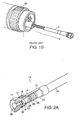
FIGS. 2A and2B illustrate amulti-piece liner 10 including aliner retainer 15 and aliner insert 20. Theliner retainer 15 has aproximal end portion 16 and adistal end portion 17. Thedistal end portion 17 includes aconnection device 18, such as ascrew thread 19. Theconnection device 18 mates with a housing within a torch's distal end to removably couple theliner retainer 15 to the torch. In embodiments, thedistal end portion 17 of theliner retainer 15 can include asealing device 21, such as, for example, a grommet, a polymer seal, or an o-ring, as shown inFIGS. 2A and2B . When theliner retainer 15 is secured to the torch, the sealingdevice 21 acts as a barrier to minimize (e.g., prevent) gas leakage from the distal end of the torch. - The
liner insert 20 has a proximal end portion (not shown), adistal end portion 22, and aliner body 23 extending therebetween. Thedistal end portion 22 of theliner insert 20 is insertable into theproximal end portion 16 of theliner retainer 15. To releasably secure the two pieces of theliner 10 together, (e.g., to secure theliner insert 20 to the liner retainer 15) thedistal end portion 22 includes one ormore connection elements 25, such as, for example, ascrew thread 26. Theconnection element 25 couples the two pieces of theliner 10 together so as to require application of a predetermined force to decouple theliner insert 20 from the liner retainer 15 (e.g., the force required to unscrew theliner insert 20 from the liner retainer 15). In some embodiments, a sealingelement 28, such as an o-ring or a grommet can be located between a coupledliner insert 20 andliner retainer 15 so as to prevent or minimize leakage of a gas (e.g., a shielding gas) into the lumen of theliner 10. - Referring to
FIGS. 3A and3B , there are many ways of releasably coupling theliner retainer 15 and theliner insert 20. Instead of using a screw thread, as described above, theliner retainer 15 and theliner insert 20 can be releasably coupled together with a compression-fit element, such as, for example, one or more o-rings 40. The o-rings 40 are deformable structures that deform under compression. As theliner insert 20 is inserted into theproximal end portion 16 of theliner retainer 15, the o-rings 40 deform under a compressive force to allow the insert to pass into theliner retainer 15. Once thedistal end portion 22 of theliner insert 20 is within theliner retainer 15, the o-rings 40 substantially return to their original state and hold theliner insert 20 within theliner retainer 15. Theliner insert 20 can be removed from the attachedliner retainer 15 by pulling the liner insert away from the liner retainer (e.g., the o-rings 40 will deform when compressed against theproximal end portion 16 of the liner retainer 15). - Both the
liner retainer 15 and theliner insert 20 can be made for a metal, such as, for example, aluminum, steel, copper or a metal alloy such as, for example, brass. In one embodiment, theliner insert 20 is made from multiple pieces which are formed from substantially the same materials. Theliner insert 20 is made from multiple pieces, which are formed from different materials. For example, in embodiments, thedistal end portion 22 of theliner insert 20 is a substantially solid piece of a metal alloy, such as, for example, brass and theliner body 23 and the proximal end portion of theliner insert 20 is a partially open structure, such as a metal (e.g., aluminum) coil. To attach the two pieces of theliner insert 20 together, thedistal end portion 22 is crimped on to theliner body 23 as shown inFIGS. 2B and3B . In embodiments, themulti-piece liner insert 20 is attached together with an adhesive positioned between thedistal end portion 22 and theliner body 23. In certain embodiment, theliner insert 20 is made from a single piece of metal or metal alloy, and theliner body 23 portion of theliner insert 20 is treated (e.g., mechanically treated, chemically treated) to increase the flexibility of theliner body 23. For example, a portion of theliner insert 20 corresponding to theliner body 23 can be laser cut to include openings which increase the flexibility of theliner body 23. - The distal ends of the
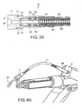
liner retainer 15 and theliner insert 20 each include anaperture wire feeder 3 to pass into theliner 10 and through theliner body 23. Theliner body 23 provides a passageway for thewire 37 to travel in between thewire feeder 3 and aproximal end 40 of thetorch 1. (See,FIG. 4A ). Theliner body 23 is a flexible structure (e.g., a metal coil, a slotted metal tube) that can bend along with movement of the torch while maintaining an open passageway for thewire 37 to travel through. In some embodiments, theliner body 23 can be protected with acoating 24, such as a heat shrink wrap coating, that prevents particulates from passing into theliner body 23. (See,FIGS. 2A-3B ). - During operation of the torch (e.g., 5 to 12 months of substantially continuous operation), gas and heat cause the
liner insert 20, especially theliner body 23 and proximal end portion, to slowly begin to be consumed. To maintain an open passageway for thewire 37, theliner insert 20 can be replaced after 3 months, 4 months, 5 months, or 6 months of use or whenever a welding torch operator decides to replace the liner insert. Referring toFIG. 4B , the welding torch operator can easily remove the used liner insert 20 from thetorch 1 by first removing thenozzle 4,contact tip 42, and thegas diffuser 44 from theproximal end 40 of thetorch 1 and then applying a force (e.g., unscrewing, pulling) to the exposed proximal end portion of theliner insert 20 to decouple the liner insert from theliner retainer 15. The welding torch operator can then insert a new liner insert 20' into the torch over thewire 37 at theproximal end 40 of the torch and attach the new liner insert 20' toliner retainer 15, which is already secured to the distal end of the torch. (See,FIG. 4C ). - In general, to install and remove the liner according to the present invention within or from a torch attached to a robotic arm, the welding torch operator first removes the
nozzle 4,contact tip 42, andgas diffuser 44 from theproximal end 40 of the torch. Then, the welding torch operator removes thetorch 1 from thewire feeder 3 to install theliner retainer 15 within adistal end 46 of the torch 1 (e.g., screws theliner retainer 15 into a housing forming thedistal end 46 of the torch 1). Once theliner retainer 15 is installed, thetorch 1 is re-installed into thewire feeder 3 and thewire 37 is fed from thedistal end 46 through theaperture 30 in theliner retainer 15 to theproximal end 40 of thetorch 1. - In the next step of the installation process, the
liner insert 20 is inserted from theproximal end 40 of the welding torch and is guided over thewire 37 to theliner retainer 15, which is secured to thedistal end 46 of thetorch 1. Upon reaching theliner retainer 15, thedistal end portion 22 of theliner insert 20 is inserted into theproximal end portion 16 of theliner retainer 15 and is fastened to theliner retainer 15 by, for example, screwing or pushing theliner insert 20 into theliner retainer 15 from the proximal end of theliner insert 20. Once theliner insert 20 has been fastened to theliner retainer 15, a portion of theliner insert 20 protruding from the proximal end of the torch is cut so that a desired or predetermined length of the liner insert remains protruding from the welding torch (e.g., liner insert extends about 0.1 centimeters to about 10 centimeters pass the welding torch). Next, thegas diffuser 44, thecontact tip 42, and thenozzle 4 are replaced. - After the initial installation of the
liner insert 20 andliner retainer 15 as described above, the liner can be replaced, according to the present invention, without having to remove thetorch 1 from thewire feeder 3 as is done in prior art systems and methods. For example, in the present invention the liner is formed of at least two pieces (e.g., theliner retainer 15 and the liner insert 20) and one of these pieces (e.g., the liner insert) is removed and replaced through theproximal end 40 of thetorch 1. - To replace the
liner insert 20, the welding torch operator removes thenozzle 4, thecontact tip 42, and thegas diffuser 44. The usedliner insert 20 which was originally installed is removed from theliner retainer 15 by unscrewing and/or pulling the proximal end portion of theliner insert 20. Once theliner insert 20 is decoupled from the liner retainer 15 (which remains attached to the distal end of the torch), the liner insert is pulled 20 in a proximal direction through the torch until it is fully removed. A new liner insert 20' is inserted over thewire 37 from theproximal end 40 of the torch and is inserted into the torch in adistal direction 50. (See,FIG. 4C ). The new liner insert 20' is coupled to theliner retainer 15 as described above before being cut to size. In the final step of the replacement process, thegas diffuser 44,contact tip 42, and thenozzle 4 are re-connected to theproximal end 40 of thetorch 1. The removal and installation of a portion of the liner (e.g., the liner insert) in accordance with this invention is advantageous since significant reductions in time needed for liner replacement are achieved (e.g., time saved due to not having to disconnect thedistal end 46 of the torch from theliner feeder 3 and not having to re-feed thewire 37 through the torch 1). Moreover, since thetorch 1 does not have to be removed from thewire feeder 3, less wire is consumed and operator safety is increased. - While certain embodiments have been described, other embodiments are also possible. As an example, while a liner for a welding torch has been described as including two pieces, the liner can include multiple pieces (e.g., two pieces, three pieces, four pieces, five pieces). In some embodiments, one or more of the multiple pieces is inserted and removed through the proximal end of the welding torch.
- As an additional example, while in one embodiment, the liner has been described as including a liner insert which has a sealing element (e.g., an o-ring) that prevents gases from entering into the passageway surrounding the
wire 37, in some embodiments, the liner retainer can include the sealing element. For example, an o-ring can be attached to theproximal end portion 16 of theliner retainer 15 so that when theliner insert 20 is inserted therein, the o-ring prevents a shielding gas from penetrating into the passageway between theliner retainer 15 and theliner insert 20. - As a further example, while in one embodiment, the liner has been described as being installed within a GMAW torch, in some embodiments the liner can be installed within other types of welding torches, such as, for example within a Flux Core Arc Welding (FCAW) torch.
- Variations, modifications, and other implementations of what is described herein will occur to those of ordinary skill without departing from the scope of the invention. Accordingly, the invention is not to be defined only by the preceding illustrative description, but rather more by the appended claims.
Claims (18)
- A multi-piece welding torch liner for insertion into a welding torch comprising:a liner retainer (15) adapted to be removably disposed at a distal end within the welding torch; anda liner insert (20) defining a lumen therethrough adapted to receive a wire of the welding torch and configured to be disposed within the welding torch, a distal end portion (22) of the liner insert (20) and the liner retainer (15) characterized by comprising connection elements (25, 26, 40) for removably coupling the liner insert (20) to the liner retainer (15), the connection elements (25, 26, 40) arranged to be coupled together and decoupled by application of a force to a proximal end of the liner insert without needing access to the distal end of the welding torch, wherein, when decoupled from the liner retainer (15), the liner insert (20) can be removed and replaced through a proximal end of the welding torch.
- The multi-piece welding torch liner of claim 1, wherein the connection elements comprise a screw thread (26)
- The multi-piece welding torch liner of claim 1, wherein the connection elements comprise compression-fit elements (25, 40).
- The multi-piece welding torch liner of claim 3, wherein the compression-fit elements comprise at least one o-ring (40).
- A multi-piece liner welding torch according to claim 1, wherein the liner insert (20) comprises a liner body (23) extending between the proximal end and the distal end portion (22).
- The multi-piece welding torch liner of claim 5, wherein the distal end portion (22) of the liner insert (20) comprises a solid piece and is secured to the liner body (23) of the liner insert (20), the liner body (23) being flexible.
- The multi-piece welding torch liner of claim 1, wherein the distal end portion (22) of the liner insert (20) includes a sealing element (28) disposed between the liner insert (20) and the liner retainer (15) when the liner insert (20 is removably coupled to the retainer (15) such that the sealing element (28) substantially prevents a shielding gas from passing into the lumen of the liner insert (20).
- The multi-piece welding torch liner of claim 1, wherein a proximal end portion of the liner retainer (15) includes a sealing element (28) disposed between the liner insert (20) and the liner retainer (15) when the liner insert (20) is removably coupled to the retainer (15) such that the sealing element substantially prevents a shielding gas from passing into the lumen of the liner insert (20).
- The multi-piece welding torch liner of claim 1, wherein a distal end portion (17) of the liner retainer (15) includes a sealing member (21) disposed between the liner retainer (15) and the torch such that the sealing member (21) substantially prevents a shielding gas from leaking from the distal end of the torch.
- The multi-piece welding torch liner of claim 1, wherein a distal end portion (17) of the liner retainer (15) includes a screw thread (19).
- The multi-piece welding torch liner of claim 1, wherein a distal end portion (17) of the liner retainer (15) defines an aperture (30) sized to allow an electrode wire (37) to pass through.
- A method of installing a multi-piece liner according to any one of claims 1 to 11 within a welding torch, the method comprising:inserting the liner insert (20) into a proximal end (40) of the welding torch; andsecuring the liner insert (20) to the liner retainer (15) installed onto a distal end of the welding torch.
- The method of claim 12, further comprising cutting the liner insert (20) to a predetermined length.
- The method of claim 12, further comprising feeding an electrode wire (37) through an aperture (30) in the liner retainer (15).
- The method of claim 12 comprising:feeding a wire (37) through the liner retainer (15) from the distal end of the welding torch; andinserting the liner insert (20) into a proximal end of the welding torch comprises passing the liner insert (20) over the wire (37) through the proximal end (40) of the welding torch.
- A method of removing a first liner insert of a multi-piece liner according to any one of claims 1 to 11 within a welding torch, the method comprising:decoupling the liner insert (20) from a liner retainer (15) secured to a distal end of the welding torch; andremoving the liner insert (20) through a proximal end (40) of the welding torch.
- A method according to claim 16 comprising:removing a nozzle (4), a contact tip (42), and a gas diffuser (44) from the proximal end (40) of the welding torch to expose a proximal end of the liner insert (20) and;applying a force to the proximal end of the liner insert (20) to decouple the liner insert (20) from the liner retainer (15) secured to the distal end of the welding torch.
- A method of replacing a portion of a multi-piece liner according to any one of claims 1 to 11 within a welding torch, the method comprising:removing a first liner insert from a liner retainer (15) secured to a distal end of the welding torch in accordance with the method of claim 16, andinstalling a second liner insert into the proximal end (40) of the welding torch in accordance with the method of claim 12.
Applications Claiming Priority (3)
| Application Number | Priority Date | Filing Date | Title |
|---|---|---|---|
| US49926303P | 2003-08-29 | 2003-08-29 | |
| US10/910,785 US7309844B2 (en) | 2003-08-29 | 2004-08-03 | Multi-piece front loading liner |
| PCT/CA2004/001573 WO2005021199A1 (en) | 2003-08-29 | 2004-08-27 | Multi-piece front loading liner |
Publications (3)
| Publication Number | Publication Date |
|---|---|
| EP1658155A1 EP1658155A1 (en) | 2006-05-24 |
| EP1658155A4 EP1658155A4 (en) | 2008-07-23 |
| EP1658155B1 true EP1658155B1 (en) | 2015-07-15 |
Family
ID=34396181
Family Applications (1)
| Application Number | Title | Priority Date | Filing Date |
|---|---|---|---|
| EP04761737.8A Active EP1658155B1 (en) | 2003-08-29 | 2004-08-27 | Multi-piece front loading liner |
Country Status (6)
| Country | Link |
|---|---|
| US (1) | US7309844B2 (en) |
| EP (1) | EP1658155B1 (en) |
| JP (1) | JP2007504002A (en) |
| CA (1) | CA2535864C (en) |
| ES (1) | ES2550097T3 (en) |
| WO (1) | WO2005021199A1 (en) |
Families Citing this family (23)
| Publication number | Priority date | Publication date | Assignee | Title |
|---|---|---|---|---|
| US7244910B2 (en) * | 2005-04-08 | 2007-07-17 | Illinois Tool Works Inc. | Welding torch nipple |
| US8373094B2 (en) * | 2007-03-08 | 2013-02-12 | Illinois Tool Works Inc. | Self-adjusting liner assembly for a consumable electrode arc-welding torch |
| US8963046B2 (en) | 2007-03-08 | 2015-02-24 | Illinois Tool Works Inc. | Self-adjusting liner assembly for welding torch |
| EP2227599B1 (en) * | 2007-12-09 | 2017-08-02 | Saferack, LLC | A gangway and method for manufacturing same |
| US8261393B2 (en) * | 2008-08-10 | 2012-09-11 | Saferack, Llc | Fall restraint equipment component and method for manufacturing the same |
| US8338753B2 (en) * | 2010-04-30 | 2012-12-25 | Lincoln Global, Inc. | Contact tip and diffuser |
| AT509589B1 (en) * | 2010-06-11 | 2011-10-15 | Fronius Int Gmbh | SYSTEM FOR FIXING A WIRE SEDE IN A COUPLING AND WIRE INJECTION NOZZLE FOR SUCH A FASTENING SYSTEM |
| CA2834703C (en) * | 2011-06-06 | 2016-07-26 | Illinois Tool Works Inc. | Self-adjusting liner assembly for welding torch |
| AU2013209396B2 (en) * | 2012-01-19 | 2016-07-07 | Victor Equipment Company | Universal conduit assembly for a welding torch |
| US9186746B2 (en) | 2012-09-14 | 2015-11-17 | Illinois Tool Works Inc. | Jump liner for push-pull MIG torch |
| US20140110386A1 (en) * | 2012-10-23 | 2014-04-24 | Robert J. Centner | Compressible end-fitting for welding gun liner |
| US9364915B2 (en) | 2013-03-15 | 2016-06-14 | Lincoln Global, Inc. | Welding diffuser insert |
| AT514572B1 (en) * | 2013-09-12 | 2015-02-15 | Fronius Int Gmbh | welding torch |
| CN104475944A (en) * | 2014-11-26 | 2015-04-01 | 泰佰亿(山东)工业有限公司 | Welding-gun wire feeding pipe chuck |
| US20160339533A1 (en) * | 2015-05-18 | 2016-11-24 | Abb Technology Ag | Robotically controlled gas tungsten arc welder and method for operating the same |
| US9713853B1 (en) * | 2016-02-29 | 2017-07-25 | Lincoln Global, Inc. | Wire feeder |
| US20200376585A1 (en) * | 2019-05-31 | 2020-12-03 | Illinois Tool Works Inc. | Welding torch and wire feeder that use electrode wire for voltage sensing |
| EP3799995A1 (en) | 2019-10-03 | 2021-04-07 | SKS Welding Systems GmbH | Arc welding torch |
| EP3799993B1 (en) | 2019-10-03 | 2024-04-03 | SKS Welding Systems GmbH | Arc welding torch |
| EP3799994A1 (en) | 2019-10-03 | 2021-04-07 | SKS Welding Systems GmbH | Arc welding torch |
| US11591802B1 (en) | 2020-02-28 | 2023-02-28 | Material Control, Inc. | Modular access system |
| US20210331267A1 (en) * | 2020-04-28 | 2021-10-28 | American Torch Tip Company | Quick-change liner for use in a removable gooseneck assembled in a welding torch. |
| CN112475698B (en) * | 2020-10-14 | 2022-06-17 | 安徽科技学院 | Welding device for producing MOSFET device |
Family Cites Families (19)
| Publication number | Priority date | Publication date | Assignee | Title |
|---|---|---|---|---|
| IT500124A (en) * | 1952-01-31 | |||
| US3261962A (en) * | 1964-11-24 | 1966-07-19 | Union Carbide Corp | Metal arc welding torch |
| US3783233A (en) | 1967-10-04 | 1974-01-01 | Co Ordinated Ind Inc | Welding gun cooling structure and electrode tip retainer |
| US4105891A (en) * | 1975-01-13 | 1978-08-08 | Union Carbide Corporation | Metal-inert-gas welding torch |
| US4158763A (en) | 1977-08-04 | 1979-06-19 | Moerke Delford A | Curved nozzle welding gun |
| US4403136A (en) | 1981-03-17 | 1983-09-06 | Lenco, Inc. | Arc welding gun with handle assembly |
| JPS5896866U (en) * | 1981-12-23 | 1983-07-01 | 谷田 博 | Conduit tube for wire feeding |
| US4521670A (en) | 1983-09-01 | 1985-06-04 | General Electric Company | Gas metal arc welding torch with vision system |
| US4582979A (en) * | 1984-09-10 | 1986-04-15 | Moerke Delford A | Arc welding system and docking assembly therefor |
| JPH084937B2 (en) * | 1987-04-02 | 1996-01-24 | 日本ビンツエル株式会社 | Welding conduit cable and manufacturing method thereof |
| JP2552973B2 (en) * | 1991-10-24 | 1996-11-13 | 新日本製鐵株式会社 | Welding device with guide pipe for feeding multiple wires |
| US5278392A (en) * | 1992-02-18 | 1994-01-11 | Tomkins Industries, Inc. | Self-cleaning nozzle for a gas welding torch |
| US5384447A (en) | 1993-01-06 | 1995-01-24 | Bernard Welding Equipment Company | Electric arc welding gun |
| US5782987A (en) | 1997-05-02 | 1998-07-21 | Furman; James Edmond | MIG welder wire cleaning apparatus and method |
| AU7556998A (en) | 1997-05-06 | 1998-11-27 | David Royd O'neill | Improvements in and relating to welding wire feeders |
| US6130407A (en) | 1998-07-29 | 2000-10-10 | Tregaskiss, Ltd. | Arc welding torch |
| US6841753B1 (en) | 1999-08-06 | 2005-01-11 | International Aluminium Holdings Limited | Welding apparatus and method |
| US6627848B2 (en) | 2001-04-06 | 2003-09-30 | Lincoln Global, Inc. | Guide device for electric arc torch welding |
| ATE507024T1 (en) | 2001-11-07 | 2011-05-15 | Commw Scient Ind Res Org | TOUCH TIP FOR ELECTRIC ARC WELDING USING A WIRE |
-
2004
- 2004-08-03 US US10/910,785 patent/US7309844B2/en active Active
- 2004-08-27 WO PCT/CA2004/001573 patent/WO2005021199A1/en active Application Filing
- 2004-08-27 CA CA2535864A patent/CA2535864C/en active Active
- 2004-08-27 ES ES04761737.8T patent/ES2550097T3/en active Active
- 2004-08-27 JP JP2006524192A patent/JP2007504002A/en active Pending
- 2004-08-27 EP EP04761737.8A patent/EP1658155B1/en active Active
Also Published As
| Publication number | Publication date |
|---|---|
| CA2535864C (en) | 2014-03-25 |
| JP2007504002A (en) | 2007-03-01 |
| EP1658155A4 (en) | 2008-07-23 |
| ES2550097T3 (en) | 2015-11-04 |
| WO2005021199B1 (en) | 2005-05-19 |
| US7309844B2 (en) | 2007-12-18 |
| US20050072764A1 (en) | 2005-04-07 |
| CA2535864A1 (en) | 2005-03-10 |
| WO2005021199A1 (en) | 2005-03-10 |
| EP1658155A1 (en) | 2006-05-24 |
Similar Documents
| Publication | Publication Date | Title |
|---|---|---|
| EP1658155B1 (en) | Multi-piece front loading liner | |
| US10786860B2 (en) | Welding gun having non-threading contact tip | |
| US7342200B2 (en) | Torch for arc welding | |
| US6852950B2 (en) | Welding gun having a removable nozzle end portion and method for operating same | |
| CN102648069B (en) | The welding gun that parts reduce and welding system; There is the cable bearing assembly of insulating sleeve | |
| EP2804714B1 (en) | Universal conduit assembly for a welding torch | |
| US7329827B2 (en) | Wire-guide nozzle assembly for a robotic TIG welding torch | |
| US9895762B2 (en) | Wire feeder connection | |
| JP2018027568A (en) | Torch clamp | |
| EP3778091B1 (en) | Welding torch | |
| CA2002503C (en) | Extracting nozzle structure in welding gun | |
| US20230166346A1 (en) | Welding torch neck adapters and welding torches including neck adapters | |
| EP0794029B1 (en) | Attachment for welding torch | |
| JP2920249B2 (en) | Arc welding torch using consumable electrodes | |
| CN115884844A (en) | Arc torch device with anti-kink device for welding wire | |
| CN115038542A (en) | Arc welding torch | |
| WO1998042472A1 (en) | Welding torch tip and welding torch | |
| CA2239198A1 (en) | Ceramic insert for welding torch |
Legal Events
| Date | Code | Title | Description |
|---|---|---|---|
| PUAI | Public reference made under article 153(3) epc to a published international application that has entered the european phase |
Free format text: ORIGINAL CODE: 0009012 |
|
| 17P | Request for examination filed |
Effective date: 20060316 |
|
| AK | Designated contracting states |
Kind code of ref document: A1 Designated state(s): AT BE BG CH CY CZ DE DK EE ES FI FR GB GR HU IE IT LI LU MC NL PL PT RO SE SI SK TR |
|
| DAX | Request for extension of the european patent (deleted) | ||
| A4 | Supplementary search report drawn up and despatched |
Effective date: 20080623 |
|
| RIC1 | Information provided on ipc code assigned before grant |
Ipc: F23D 14/40 20060101ALI20080617BHEP Ipc: B23K 9/28 20060101ALI20080617BHEP Ipc: B23K 9/29 20060101ALI20080617BHEP Ipc: B23K 9/32 20060101ALI20080617BHEP Ipc: B23K 9/24 20060101ALI20080617BHEP Ipc: B23K 31/02 20060101ALI20080617BHEP Ipc: B23K 37/00 20060101ALI20080617BHEP Ipc: B23K 9/00 20060101AFI20050316BHEP |
|
| RAP1 | Party data changed (applicant data changed or rights of an application transferred) |
Owner name: ITW CANADA |
|
| RAP1 | Party data changed (applicant data changed or rights of an application transferred) |
Owner name: ILLINOIS TOOL WORKS INC. |
|
| 17Q | First examination report despatched |
Effective date: 20081002 |
|
| RAP1 | Party data changed (applicant data changed or rights of an application transferred) |
Owner name: ILLINOIS TOOL WORKS INC. |
|
| GRAP | Despatch of communication of intention to grant a patent |
Free format text: ORIGINAL CODE: EPIDOSNIGR1 |
|
| INTG | Intention to grant announced |
Effective date: 20150511 |
|
| GRAS | Grant fee paid |
Free format text: ORIGINAL CODE: EPIDOSNIGR3 |
|
| GRAA | (expected) grant |
Free format text: ORIGINAL CODE: 0009210 |
|
| AK | Designated contracting states |
Kind code of ref document: B1 Designated state(s): AT BE BG CH CY CZ DE DK EE ES FI FR GB GR HU IE IT LI LU MC NL PL PT RO SE SI SK TR |
|
| REG | Reference to a national code |
Ref country code: CH Ref legal event code: EP Ref country code: GB Ref legal event code: FG4D |
|
| REG | Reference to a national code |
Ref country code: IE Ref legal event code: FG4D |
|
| REG | Reference to a national code |
Ref country code: AT Ref legal event code: REF Ref document number: 736523 Country of ref document: AT Kind code of ref document: T Effective date: 20150815 |
|
| REG | Reference to a national code |
Ref country code: DE Ref legal event code: R096 Ref document number: 602004047509 Country of ref document: DE |
|
| REG | Reference to a national code |
Ref country code: FR Ref legal event code: PLFP Year of fee payment: 12 |
|
| PGFP | Annual fee paid to national office [announced via postgrant information from national office to epo] |
Ref country code: GB Payment date: 20150827 Year of fee payment: 12 |
|
| REG | Reference to a national code |
Ref country code: ES Ref legal event code: FG2A Ref document number: 2550097 Country of ref document: ES Kind code of ref document: T3 Effective date: 20151104 |
|
| REG | Reference to a national code |
Ref country code: AT Ref legal event code: MK05 Ref document number: 736523 Country of ref document: AT Kind code of ref document: T Effective date: 20150715 |
|
| REG | Reference to a national code |
Ref country code: NL Ref legal event code: FP |
|
| PG25 | Lapsed in a contracting state [announced via postgrant information from national office to epo] |
Ref country code: FI Free format text: LAPSE BECAUSE OF FAILURE TO SUBMIT A TRANSLATION OF THE DESCRIPTION OR TO PAY THE FEE WITHIN THE PRESCRIBED TIME-LIMIT Effective date: 20150715 Ref country code: GR Free format text: LAPSE BECAUSE OF FAILURE TO SUBMIT A TRANSLATION OF THE DESCRIPTION OR TO PAY THE FEE WITHIN THE PRESCRIBED TIME-LIMIT Effective date: 20151016 |
|
| PG25 | Lapsed in a contracting state [announced via postgrant information from national office to epo] |
Ref country code: AT Free format text: LAPSE BECAUSE OF FAILURE TO SUBMIT A TRANSLATION OF THE DESCRIPTION OR TO PAY THE FEE WITHIN THE PRESCRIBED TIME-LIMIT Effective date: 20150715 Ref country code: PL Free format text: LAPSE BECAUSE OF FAILURE TO SUBMIT A TRANSLATION OF THE DESCRIPTION OR TO PAY THE FEE WITHIN THE PRESCRIBED TIME-LIMIT Effective date: 20150715 Ref country code: PT Free format text: LAPSE BECAUSE OF FAILURE TO SUBMIT A TRANSLATION OF THE DESCRIPTION OR TO PAY THE FEE WITHIN THE PRESCRIBED TIME-LIMIT Effective date: 20151116 Ref country code: SE Free format text: LAPSE BECAUSE OF FAILURE TO SUBMIT A TRANSLATION OF THE DESCRIPTION OR TO PAY THE FEE WITHIN THE PRESCRIBED TIME-LIMIT Effective date: 20150715 |
|
| REG | Reference to a national code |
Ref country code: CH Ref legal event code: PL |
|
| REG | Reference to a national code |
Ref country code: DE Ref legal event code: R097 Ref document number: 602004047509 Country of ref document: DE |
|
| PG25 | Lapsed in a contracting state [announced via postgrant information from national office to epo] |
Ref country code: EE Free format text: LAPSE BECAUSE OF FAILURE TO SUBMIT A TRANSLATION OF THE DESCRIPTION OR TO PAY THE FEE WITHIN THE PRESCRIBED TIME-LIMIT Effective date: 20150715 Ref country code: CZ Free format text: LAPSE BECAUSE OF FAILURE TO SUBMIT A TRANSLATION OF THE DESCRIPTION OR TO PAY THE FEE WITHIN THE PRESCRIBED TIME-LIMIT Effective date: 20150715 Ref country code: LI Free format text: LAPSE BECAUSE OF NON-PAYMENT OF DUE FEES Effective date: 20150831 Ref country code: DK Free format text: LAPSE BECAUSE OF FAILURE TO SUBMIT A TRANSLATION OF THE DESCRIPTION OR TO PAY THE FEE WITHIN THE PRESCRIBED TIME-LIMIT Effective date: 20150715 Ref country code: MC Free format text: LAPSE BECAUSE OF FAILURE TO SUBMIT A TRANSLATION OF THE DESCRIPTION OR TO PAY THE FEE WITHIN THE PRESCRIBED TIME-LIMIT Effective date: 20150715 Ref country code: CH Free format text: LAPSE BECAUSE OF NON-PAYMENT OF DUE FEES Effective date: 20150831 Ref country code: SK Free format text: LAPSE BECAUSE OF FAILURE TO SUBMIT A TRANSLATION OF THE DESCRIPTION OR TO PAY THE FEE WITHIN THE PRESCRIBED TIME-LIMIT Effective date: 20150715 |
|
| PLBE | No opposition filed within time limit |
Free format text: ORIGINAL CODE: 0009261 |
|
| STAA | Information on the status of an ep patent application or granted ep patent |
Free format text: STATUS: NO OPPOSITION FILED WITHIN TIME LIMIT |
|
| PG25 | Lapsed in a contracting state [announced via postgrant information from national office to epo] |
Ref country code: RO Free format text: LAPSE BECAUSE OF FAILURE TO SUBMIT A TRANSLATION OF THE DESCRIPTION OR TO PAY THE FEE WITHIN THE PRESCRIBED TIME-LIMIT Effective date: 20150715 |
|
| REG | Reference to a national code |
Ref country code: IE Ref legal event code: MM4A |
|
| 26N | No opposition filed |
Effective date: 20160418 |
|
| PG25 | Lapsed in a contracting state [announced via postgrant information from national office to epo] |
Ref country code: IE Free format text: LAPSE BECAUSE OF NON-PAYMENT OF DUE FEES Effective date: 20150827 |
|
| REG | Reference to a national code |
Ref country code: FR Ref legal event code: PLFP Year of fee payment: 13 |
|
| PG25 | Lapsed in a contracting state [announced via postgrant information from national office to epo] |
Ref country code: SI Free format text: LAPSE BECAUSE OF FAILURE TO SUBMIT A TRANSLATION OF THE DESCRIPTION OR TO PAY THE FEE WITHIN THE PRESCRIBED TIME-LIMIT Effective date: 20150715 |
|
| PGFP | Annual fee paid to national office [announced via postgrant information from national office to epo] |
Ref country code: NL Payment date: 20160826 Year of fee payment: 13 |
|
| GBPC | Gb: european patent ceased through non-payment of renewal fee |
Effective date: 20160827 |
|
| PG25 | Lapsed in a contracting state [announced via postgrant information from national office to epo] |
Ref country code: HU Free format text: LAPSE BECAUSE OF FAILURE TO SUBMIT A TRANSLATION OF THE DESCRIPTION OR TO PAY THE FEE WITHIN THE PRESCRIBED TIME-LIMIT; INVALID AB INITIO Effective date: 20040827 Ref country code: BG Free format text: LAPSE BECAUSE OF FAILURE TO SUBMIT A TRANSLATION OF THE DESCRIPTION OR TO PAY THE FEE WITHIN THE PRESCRIBED TIME-LIMIT Effective date: 20150715 |
|
| PG25 | Lapsed in a contracting state [announced via postgrant information from national office to epo] |
Ref country code: CY Free format text: LAPSE BECAUSE OF FAILURE TO SUBMIT A TRANSLATION OF THE DESCRIPTION OR TO PAY THE FEE WITHIN THE PRESCRIBED TIME-LIMIT Effective date: 20150715 |
|
| PG25 | Lapsed in a contracting state [announced via postgrant information from national office to epo] |
Ref country code: GB Free format text: LAPSE BECAUSE OF NON-PAYMENT OF DUE FEES Effective date: 20160827 Ref country code: BE Free format text: LAPSE BECAUSE OF NON-PAYMENT OF DUE FEES Effective date: 20150831 |
|
| REG | Reference to a national code |
Ref country code: FR Ref legal event code: PLFP Year of fee payment: 14 |
|
| PGFP | Annual fee paid to national office [announced via postgrant information from national office to epo] |
Ref country code: PL Payment date: 20180326 Year of fee payment: 4 |
|
| PG25 | Lapsed in a contracting state [announced via postgrant information from national office to epo] |
Ref country code: LU Free format text: LAPSE BECAUSE OF NON-PAYMENT OF DUE FEES Effective date: 20150827 |
|
| REG | Reference to a national code |
Ref country code: NL Ref legal event code: MM Effective date: 20170901 |
|
| PG25 | Lapsed in a contracting state [announced via postgrant information from national office to epo] |
Ref country code: NL Free format text: LAPSE BECAUSE OF NON-PAYMENT OF DUE FEES Effective date: 20170901 |
|
| REG | Reference to a national code |
Ref country code: FR Ref legal event code: PLFP Year of fee payment: 15 |
|
| REG | Reference to a national code |
Ref country code: ES Ref legal event code: FD2A Effective date: 20190918 |
|
| PG25 | Lapsed in a contracting state [announced via postgrant information from national office to epo] |
Ref country code: ES Free format text: LAPSE BECAUSE OF NON-PAYMENT OF DUE FEES Effective date: 20180828 |
|
| PGFP | Annual fee paid to national office [announced via postgrant information from national office to epo] |
Ref country code: FR Payment date: 20200825 Year of fee payment: 17 |
|
| PG25 | Lapsed in a contracting state [announced via postgrant information from national office to epo] |
Ref country code: TR Free format text: LAPSE BECAUSE OF NON-PAYMENT OF DUE FEES Effective date: 20170827 |
|
| PG25 | Lapsed in a contracting state [announced via postgrant information from national office to epo] |
Ref country code: FR Free format text: LAPSE BECAUSE OF NON-PAYMENT OF DUE FEES Effective date: 20210831 |
|
| P01 | Opt-out of the competence of the unified patent court (upc) registered |
Effective date: 20230606 |
|
| PGFP | Annual fee paid to national office [announced via postgrant information from national office to epo] |
Ref country code: IT Payment date: 20230822 Year of fee payment: 20 |
|
| PGFP | Annual fee paid to national office [announced via postgrant information from national office to epo] |
Ref country code: DE Payment date: 20230829 Year of fee payment: 20 |