EP1656242B1 - Capillary imprinting technique - Google Patents
Capillary imprinting technique Download PDFInfo
- Publication number
- EP1656242B1 EP1656242B1 EP04781082A EP04781082A EP1656242B1 EP 1656242 B1 EP1656242 B1 EP 1656242B1 EP 04781082 A EP04781082 A EP 04781082A EP 04781082 A EP04781082 A EP 04781082A EP 1656242 B1 EP1656242 B1 EP 1656242B1
- Authority
- EP
- European Patent Office
- Prior art keywords
- mold
- conformable material
- substrate
- region
- sub
- Prior art date
- Legal status (The legal status is an assumption and is not a legal conclusion. Google has not performed a legal analysis and makes no representation as to the accuracy of the status listed.)
- Active
Links
- 238000000034 method Methods 0.000 title claims abstract description 37
- 239000000463 material Substances 0.000 claims abstract description 96
- 239000000758 substrate Substances 0.000 claims abstract description 86
- 238000000059 patterning Methods 0.000 claims abstract description 10
- 230000009471 action Effects 0.000 claims abstract description 7
- 230000005855 radiation Effects 0.000 claims description 19
- 238000009736 wetting Methods 0.000 claims description 3
- 230000003247 decreasing effect Effects 0.000 claims description 2
- 238000000151 deposition Methods 0.000 claims 2
- 239000000203 mixture Substances 0.000 description 12
- 239000012530 fluid Substances 0.000 description 10
- 238000004519 manufacturing process Methods 0.000 description 9
- 230000008569 process Effects 0.000 description 8
- 238000009826 distribution Methods 0.000 description 7
- 239000002861 polymer material Substances 0.000 description 6
- 230000015572 biosynthetic process Effects 0.000 description 5
- 230000001419 dependent effect Effects 0.000 description 5
- KUDUQBURMYMBIJ-UHFFFAOYSA-N 2-prop-2-enoyloxyethyl prop-2-enoate Chemical compound C=CC(=O)OCCOC(=O)C=C KUDUQBURMYMBIJ-UHFFFAOYSA-N 0.000 description 4
- 239000003795 chemical substances by application Substances 0.000 description 4
- 238000012545 processing Methods 0.000 description 4
- 230000008901 benefit Effects 0.000 description 3
- 230000007423 decrease Effects 0.000 description 3
- 230000005499 meniscus Effects 0.000 description 3
- 239000010703 silicon Substances 0.000 description 3
- 229910052710 silicon Inorganic materials 0.000 description 3
- 238000003892 spreading Methods 0.000 description 3
- 230000007480 spreading Effects 0.000 description 3
- 239000000126 substance Substances 0.000 description 3
- 238000012546 transfer Methods 0.000 description 3
- PSGCQDPCAWOCSH-UHFFFAOYSA-N (4,7,7-trimethyl-3-bicyclo[2.2.1]heptanyl) prop-2-enoate Chemical compound C1CC2(C)C(OC(=O)C=C)CC1C2(C)C PSGCQDPCAWOCSH-UHFFFAOYSA-N 0.000 description 2
- XMLYCEVDHLAQEL-UHFFFAOYSA-N 2-hydroxy-2-methyl-1-phenylpropan-1-one Chemical compound CC(C)(O)C(=O)C1=CC=CC=C1 XMLYCEVDHLAQEL-UHFFFAOYSA-N 0.000 description 2
- VYPSYNLAJGMNEJ-UHFFFAOYSA-N Silicium dioxide Chemical compound O=[Si]=O VYPSYNLAJGMNEJ-UHFFFAOYSA-N 0.000 description 2
- -1 but not limited to Substances 0.000 description 2
- 239000000470 constituent Substances 0.000 description 2
- 229920006037 cross link polymer Polymers 0.000 description 2
- LNMQRPPRQDGUDR-UHFFFAOYSA-N hexyl prop-2-enoate Chemical compound CCCCCCOC(=O)C=C LNMQRPPRQDGUDR-UHFFFAOYSA-N 0.000 description 2
- 239000003999 initiator Substances 0.000 description 2
- 238000002348 laser-assisted direct imprint lithography Methods 0.000 description 2
- 238000005259 measurement Methods 0.000 description 2
- 229910052751 metal Inorganic materials 0.000 description 2
- 239000002184 metal Substances 0.000 description 2
- 238000001020 plasma etching Methods 0.000 description 2
- 238000006116 polymerization reaction Methods 0.000 description 2
- 239000004065 semiconductor Substances 0.000 description 2
- 239000007787 solid Substances 0.000 description 2
- 230000002269 spontaneous effect Effects 0.000 description 2
- JBRZTFJDHDCESZ-UHFFFAOYSA-N AsGa Chemical compound [As]#[Ga] JBRZTFJDHDCESZ-UHFFFAOYSA-N 0.000 description 1
- 206010073306 Exposure to radiation Diseases 0.000 description 1
- 229910001218 Gallium arsenide Inorganic materials 0.000 description 1
- 239000004952 Polyamide Substances 0.000 description 1
- 238000000231 atomic layer deposition Methods 0.000 description 1
- 230000009286 beneficial effect Effects 0.000 description 1
- 239000005388 borosilicate glass Substances 0.000 description 1
- 238000005219 brazing Methods 0.000 description 1
- 238000005229 chemical vapour deposition Methods 0.000 description 1
- 230000000295 complement effect Effects 0.000 description 1
- 239000002131 composite material Substances 0.000 description 1
- 238000005137 deposition process Methods 0.000 description 1
- 238000011161 development Methods 0.000 description 1
- KPUWHANPEXNPJT-UHFFFAOYSA-N disiloxane Chemical class [SiH3]O[SiH3] KPUWHANPEXNPJT-UHFFFAOYSA-N 0.000 description 1
- 238000004049 embossing Methods 0.000 description 1
- 238000005516 engineering process Methods 0.000 description 1
- 238000005530 etching Methods 0.000 description 1
- 229920002313 fluoropolymer Polymers 0.000 description 1
- 239000005350 fused silica glass Substances 0.000 description 1
- 230000002209 hydrophobic effect Effects 0.000 description 1
- VCEXCCILEWFFBG-UHFFFAOYSA-N mercury telluride Chemical compound [Hg]=[Te] VCEXCCILEWFFBG-UHFFFAOYSA-N 0.000 description 1
- 238000012986 modification Methods 0.000 description 1
- 230000004048 modification Effects 0.000 description 1
- 239000012778 molding material Substances 0.000 description 1
- 238000000465 moulding Methods 0.000 description 1
- 239000002086 nanomaterial Substances 0.000 description 1
- 230000003287 optical effect Effects 0.000 description 1
- 229920000620 organic polymer Polymers 0.000 description 1
- 238000005240 physical vapour deposition Methods 0.000 description 1
- 239000004033 plastic Substances 0.000 description 1
- 229920003023 plastic Polymers 0.000 description 1
- 229920002647 polyamide Polymers 0.000 description 1
- 229920000515 polycarbonate Polymers 0.000 description 1
- 239000004417 polycarbonate Substances 0.000 description 1
- 229920000728 polyester Polymers 0.000 description 1
- 229920000642 polymer Polymers 0.000 description 1
- 229920002635 polyurethane Polymers 0.000 description 1
- 239000004814 polyurethane Substances 0.000 description 1
- 238000012805 post-processing Methods 0.000 description 1
- 238000004886 process control Methods 0.000 description 1
- 239000010453 quartz Substances 0.000 description 1
- 230000009467 reduction Effects 0.000 description 1
- 229910052594 sapphire Inorganic materials 0.000 description 1
- 239000010980 sapphire Substances 0.000 description 1
- 239000003381 stabilizer Substances 0.000 description 1
- 229920001169 thermoplastic Polymers 0.000 description 1
- 229920001187 thermosetting polymer Polymers 0.000 description 1
- 238000001039 wet etching Methods 0.000 description 1
Images


Classifications
-
- B—PERFORMING OPERATIONS; TRANSPORTING
- B29—WORKING OF PLASTICS; WORKING OF SUBSTANCES IN A PLASTIC STATE IN GENERAL
- B29C—SHAPING OR JOINING OF PLASTICS; SHAPING OF MATERIAL IN A PLASTIC STATE, NOT OTHERWISE PROVIDED FOR; AFTER-TREATMENT OF THE SHAPED PRODUCTS, e.g. REPAIRING
- B29C59/00—Surface shaping of articles, e.g. embossing; Apparatus therefor
- B29C59/02—Surface shaping of articles, e.g. embossing; Apparatus therefor by mechanical means, e.g. pressing
-
- G—PHYSICS
- G03—PHOTOGRAPHY; CINEMATOGRAPHY; ANALOGOUS TECHNIQUES USING WAVES OTHER THAN OPTICAL WAVES; ELECTROGRAPHY; HOLOGRAPHY
- G03F—PHOTOMECHANICAL PRODUCTION OF TEXTURED OR PATTERNED SURFACES, e.g. FOR PRINTING, FOR PROCESSING OF SEMICONDUCTOR DEVICES; MATERIALS THEREFOR; ORIGINALS THEREFOR; APPARATUS SPECIALLY ADAPTED THEREFOR
- G03F7/00—Photomechanical, e.g. photolithographic, production of textured or patterned surfaces, e.g. printing surfaces; Materials therefor, e.g. comprising photoresists; Apparatus specially adapted therefor
- G03F7/0002—Lithographic processes using patterning methods other than those involving the exposure to radiation, e.g. by stamping
-
- B—PERFORMING OPERATIONS; TRANSPORTING
- B29—WORKING OF PLASTICS; WORKING OF SUBSTANCES IN A PLASTIC STATE IN GENERAL
- B29C—SHAPING OR JOINING OF PLASTICS; SHAPING OF MATERIAL IN A PLASTIC STATE, NOT OTHERWISE PROVIDED FOR; AFTER-TREATMENT OF THE SHAPED PRODUCTS, e.g. REPAIRING
- B29C35/00—Heating, cooling or curing, e.g. crosslinking or vulcanising; Apparatus therefor
- B29C35/02—Heating or curing, e.g. crosslinking or vulcanizing during moulding, e.g. in a mould
- B29C35/08—Heating or curing, e.g. crosslinking or vulcanizing during moulding, e.g. in a mould by wave energy or particle radiation
-
- B—PERFORMING OPERATIONS; TRANSPORTING
- B82—NANOTECHNOLOGY
- B82Y—SPECIFIC USES OR APPLICATIONS OF NANOSTRUCTURES; MEASUREMENT OR ANALYSIS OF NANOSTRUCTURES; MANUFACTURE OR TREATMENT OF NANOSTRUCTURES
- B82Y10/00—Nanotechnology for information processing, storage or transmission, e.g. quantum computing or single electron logic
-
- B—PERFORMING OPERATIONS; TRANSPORTING
- B82—NANOTECHNOLOGY
- B82Y—SPECIFIC USES OR APPLICATIONS OF NANOSTRUCTURES; MEASUREMENT OR ANALYSIS OF NANOSTRUCTURES; MANUFACTURE OR TREATMENT OF NANOSTRUCTURES
- B82Y40/00—Manufacture or treatment of nanostructures
-
- C—CHEMISTRY; METALLURGY
- C23—COATING METALLIC MATERIAL; COATING MATERIAL WITH METALLIC MATERIAL; CHEMICAL SURFACE TREATMENT; DIFFUSION TREATMENT OF METALLIC MATERIAL; COATING BY VACUUM EVAPORATION, BY SPUTTERING, BY ION IMPLANTATION OR BY CHEMICAL VAPOUR DEPOSITION, IN GENERAL; INHIBITING CORROSION OF METALLIC MATERIAL OR INCRUSTATION IN GENERAL
- C23F—NON-MECHANICAL REMOVAL OF METALLIC MATERIAL FROM SURFACE; INHIBITING CORROSION OF METALLIC MATERIAL OR INCRUSTATION IN GENERAL; MULTI-STEP PROCESSES FOR SURFACE TREATMENT OF METALLIC MATERIAL INVOLVING AT LEAST ONE PROCESS PROVIDED FOR IN CLASS C23 AND AT LEAST ONE PROCESS COVERED BY SUBCLASS C21D OR C22F OR CLASS C25
- C23F1/00—Etching metallic material by chemical means
- C23F1/08—Apparatus, e.g. for photomechanical printing surfaces
Landscapes
- Engineering & Computer Science (AREA)
- Chemical & Material Sciences (AREA)
- Nanotechnology (AREA)
- Physics & Mathematics (AREA)
- Crystallography & Structural Chemistry (AREA)
- General Physics & Mathematics (AREA)
- Mechanical Engineering (AREA)
- Mathematical Physics (AREA)
- Materials Engineering (AREA)
- Condensed Matter Physics & Semiconductors (AREA)
- Organic Chemistry (AREA)
- Metallurgy (AREA)
- Health & Medical Sciences (AREA)
- Theoretical Computer Science (AREA)
- Chemical Kinetics & Catalysis (AREA)
- General Chemical & Material Sciences (AREA)
- Manufacturing & Machinery (AREA)
- Toxicology (AREA)
- Oral & Maxillofacial Surgery (AREA)
- Thermal Sciences (AREA)
- Shaping Of Tube Ends By Bending Or Straightening (AREA)
- Moulds For Moulding Plastics Or The Like (AREA)
- Crystals, And After-Treatments Of Crystals (AREA)
- Printing Methods (AREA)
- Casting Or Compression Moulding Of Plastics Or The Like (AREA)
Abstract
Description
- The field of invention relates generally to micro-fabrication of structures. More particularly, the present invention is directed to patterning substrates in furtherance of the formation of structures.
- Micro-fabrication involves the fabrication of very small structures, e.g., having features on the order of micro-meters or smaller. One area in which micro-fabrication has had a sizeable impact is in the processing of integrated circuits. As the semiconductor processing industry continues to strive for larger production yields while increasing the circuits per unit area formed on a substrate, micro-fabrication becomes increasingly important. Micro-fabrication provides greater process control while allowing a reduction in the minimum feature dimension of the structures formed. Other areas of development in which micro-fabrication has been employed include biotechnology, optical technology, mechanical systems and the like.
- An exemplary micro-fabrication technique is shown in United States patent number
6,334,960 to Willson et al. Willson et al. discloses a method of forming a relief image in a substrate. The method includes having a mold make mechanical contact with the polymerizable fluid disposed on a substrate. The mold includes a relief structure. Under the compressive force created between the mold and substrate, the polymerizable fluid fills the relief structure in the mold. Thereafter, the polymerizable fluid is subjected to conditions to solidify and polymerize the same, forming a solidified polymeric material on a transfer layer that contains a relief structure complimentary.to that of the relief structure of the mold. The mold is then separated from the solid polymeric material such that a replica of the relief structure in the mold is formed in the solidified polymeric material. Post processing steps are undertaken to transfer the relief image into the substrate. - To accurately form the pattern in the polymeric material, sufficient time and force is employed to ensure that the relief structure is completely filled while controlling the distribution of the polymerizable fluid over the substrate. For example, to decrease the time required to imprint a polymerizable fluid with a given viscosity, involves increasing the compressive force between the mold and the substrate. However, too great a compressive force results in the polymerizable fluid spreading to undesired regions of the substrate. Conversely, to obtain precise control over the distribution of the polyermizable fluid over the substrate, often involves decreasing the compressive force between the mold and the substrate. As a result, the time required to imprint the polymerizable material increases. Thus, a tradeoff exists between compressive force employed and time required to imprint the polymerizable fluid.
DocumentsGB 2177342 A US 2002/066978 A1 ,US 5132069 ,US 6355198 , and
US 2003/0062334 A1 show methods for molding articles where molding material is subject to capillary action. - A need exists, therefore, to reduce the time required to pattern polymerizable fluid while maintaining adequate control of the distribution of the polymerizable fluid over the surface of the substrate.
- The present invention provides a method for patterning a substrate with a template having a mold according to
claim 1. Specifically, the movement between the mold and the substrate is controlled to a sufficient degree to attenuate, if not avoid, compressive forces between the mold and the substrate. As a result, upon initial contact of the mold with the conformable material, spontaneous capillary filling of the volume between the mold and the substrate occurs. The capillary filling creates pulling forces between the mold and the substrate, which is referred to as a negative imprint force. Many benefits result from the negative imprint force, including rapid and complete filling of the features of the mold, as well as precise control of the distribution of the conformable material of the substrate. These and other embodiments are described more fully below. -
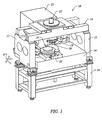
Fig. 1 is a perspective view of a patterning system in accordance with the present invention; -
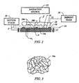
Fig. 2 is a simplified elevation view of a patterning system shown inFig. 1 ; -
Fig. 3 is a simplified representation of material from which an imprinting layer, shown inFig. 2 , is comprised before being polymerized and cross-linked; -
Fig. 4 is a simplified representation of cross-linked polymer material into which the material shown inFig. 3 is transformed after being subjected to radiation; -
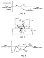
Fig. 5 is a simplified elevation view of a mold spaced-apart from the imprinting layer, shown inFig. 2 , after patterning of the imprinting layer; -
Fig. 6 is a graphical representation of the forces to which a mold, shown inFig. 2 , is subjected during imprinting processes, in accordance with one embodiment of the present invention; -
Fig. 7 is a detailed view of the system shown inFig. 1 ; -
Fig. 8 is a graphical representation of the forces to which a mold, shown inFig. 2 , is subjected during imprinting processes in accordance with an alternate embodiment of the present invention; -
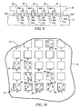
Fig. 9 is a close-up view of the template, shown inFig. 1 , having multiple molds formed thereon to concurrently imprint multiple pattern regions on the substrate in accordance with the present invention; -
Fig. 10 is a top down plan view of a portion of the substrate, shown inFig. 1 , showing a plurality of regions that are in superimposition with the molds of template, shown inFig. 9 , in accordance with the present invention; - .
Fig. 11 is a detailed side view showing a portion of the mold, shown inFig. 2 , extending from an edge of the substrate, in accordance with an alternate embodiment of the present invention; and -
Fig. 12 is a simplified elevation view of material in an imprint device and substrate employed with the present invention in accordance with an alternate embodiment. -
Fig. 1 depicts alithographic system 10 in accordance with one embodiment of the present invention that includes a pair of spaced-apart bridge supports 12 having abridge 14 and astage support 16 extending therebetween.Bridge 14 andstage support 16 are spaced-apart. Coupled tobridge 14 is animprint head 18, which extends frombridge 14 towardstage support 16. Disposed uponstage support 16 to faceimprint head 18 is amotion stage 20.Motion stage 20 is configured to move with respect tostage support 16 along X and Y axes, and may optionally facilitate movement along a Z axis, as well. Aradiation source 22 is coupled tolithographic system 10 to impinge actinic radiation uponmotion stage 20. As shown,radiation source 22 is coupled tobridge 14 and includes apower generator 23 connected toradiation source 22. - Referring to both
Figs. 1 and2 , connected toimprint head 18 is atemplate 26 having amold 28 thereon.Mold 28 includes a plurality of features defined by a plurality of spaced-apart recessions 28a and protrusions 28b. The plurality of features defines an original pattern that is to be transferred into asubstrate 31 positioned onmotion stage 20.Substrate 31 may comprise of a bare wafer or a wafer with one or more layers disposed thereon. To that end,imprint head 18 is adapted to move along the Z axis and vary a distance "d" betweenmold 28 andsubstrate 31. In this manner, the features onmold 28 may be imprinted into a conformable region ofsubstrate 31, discussed more fully below.Radiation source 22 is located so thatmold 28 is positioned betweenradiation source 22 andsubstrate 31. As a result,mold 28 is fabricated from material that allows it to be substantially transparent to the radiation produced byradiation source 22. - Referring to both
Figs. 2 and 3 , a conformable region, such as animprinting layer 34, is disposed on a portion ofsurface 32 that presents a substantially planar profile. It should be understood that the conformable region may be formed using any known technique to produce conformable material, such as a hot embossing process disclosed in United States patent number5,772,905 to Chou , or a laser assisted direct imprinting (LADI) process of the type described by Chou et al. in Ultrafast and Direct Imprint of Nanostructures in Silicon, Nature, Col. 417, pp. 835-837, June 2002. In the present embodiment, however, conformable region consists ofimprinting layer 34 being deposited as a plurality of spaced-apartdiscrete droplets 36 ofimprinting material 36a onsubstrate 31, discussed more fully below.Imprinting layer 34 is formed from imprintingmaterial 36a that may be selectively polymerized and cross-linked to record a pattern that is complementary to the original pattern, defining a recorded pattern.Imprinting material 36a is shown inFig. 4 as being cross-linked atpoints 36b, formingcross-linked polymer material 36c. - Referring to
Figs. 2, 3 and4 , after a desired distance "d" has been reached,radiation source 22 produces actinic radiation that polymerizes andcross-links imprinting material 36a, formingpolymer material 36c in which a substantial portion thereof is cross-linked. As a result,imprinting material 36a transforms topolymer material 36c, which is a solid, formingimprinting layer 134, shown inFig. 5 . Specifically,polymer material 36c is solidified to provideside 34c ofimprinting layer 134 with a shape conforming to a shape of asurface 28c ofmold 28, withimprinting layer 134 havingrecesses 30. After imprintinglayer 134 is transformed to consist ofpolymer material 36c, shown inFig. 4 ,imprint head 18, shown inFig. 2 , is moved to increase distance "d" so thatmold 28 andimprinting layer 134 are spaced-apart. - Referring to
Figs. 2, 3 and5 , the pattern recorded inimprinting layer 34 may be produced primarily, if not solely, by capillary force of imprintingmaterial 36a withmold 28 and/orsubstrate 31. The amount of external force, i.e., non-capillary pressure, employed is dependent upon several factors, including the composition ofimprinting material 36a, the resulting thickness ofimprinting layer 34 and the area over whichimprinting material 36a must spread. For example, a fixed composition ofimprinting material 36a and a fixed area over whichimprinting material 36a is to spread, there is a minimum distance d' betweensubstrate 31 and protrusions 28b that is reached before capillary filling occurs. Were thickness t2 ofimprinting layer 34 greater than d' very little capillary pressure would be employed to spreadimprinting material 36a, i.e., a greater amount of compressive forces would be exerted onmold 28. In that case, an external positive force F is employed to spreadimprinting material 36a indroplets 36 in a desirable amount of time. In this manner, imprintingmaterial 36a indroplets 36 is spread primarily with external pressure applied thereto viamold 28 a sufficient amount until imprintingmaterial 36a is spread betweenmold 28 andsubstrate 31, as desired. - Assuming, for the fixed area and fixed composition of
imprinting material 36a, that t2 is less than or equal to d', the amount of capillary pressure becomes primarily a function of thickness t2 and the fraction of the fixed area to be filled withimprinting material 36a, i.e., the portion of the fixed area upon whichimprinting material 36a is absent. More particularly, the amount of capillary pressure generated during imprinting is proportional to the fraction of the fixed area to be filled and inversely proportional to thickness t2. Understanding that thickness t2 is dependent upon distance d, it becomes important to carefully control distance d during the imprinting process. Control of distance d may be frustrated by compliance inimprint head 18 and/ ormotion stage 20. In this situation, rapid capillary filling occurs upon contact ofdroplets 36 withmold 28. Specifically, relative movement betweenmold 28 andsubstrate 31 is controlled so that distance d decreases to placesurface 28c ofmold 28 in contact withdroplets 36. Contact withsurface 28c ofmold 28 distorts the hemispherical shape ofdroplets 36, causing the same to initiate wetting/spreading acrosssurface 28c ofmold 28, as well as oversurface 32 ofsubstrate 31. The distance d continues to decrease until a volume V is defined betweenmold 28 and the region ofsubstrate 31 in superimposition therewith fills withimprinting material 36a through capillary action. - Referring to
Figs. 2, 3 and6 , force measurements onmold 28 during an exemplary capillary imprint method is shown with point 80 whereindroplets 36 are initially in contact with mold. As shown, the compressive and tensile forces to whichmold 28 is subjected are substantially zero. Atpoint 82, capillary filling of volume V is initiated so thatmold 28 is subjected to tension force T. Atpoint 84, tension force T has reached a maximum magnitude, i.e., substantially all ofimprinting material 36a in volume V is undergoing capillary attraction withmold 28 andsubstrate 31. - Specifically, relative movement of
mold 28 andsubstrate 31 is effectuated to attenuate, if not avoid, subjectingmold 28 to compressive forces resulting from contact withimprinting material 36a. The compressive forces C1 and C2, shown inFig. 7 , that are sought to be minimized result fromimprint head 18 pushing againstmold 28 asimprinting material 36a pushes againstmold 28 during imprinting. This facilitates spontaneous capillary filling of volume V occurring upon initial contact ofmold 28 withimprinting material 36a indroplets 36. The capillary filling creates pulling/tensional forces, T, uponmold 28, referred to as a negative imprint force. The negative imprinting force, or tension force, T causes elongation ofimprint head 18 andsubstrate 31 subjectingmold 28 to tension force T. - However, too great a negative imprint force may compromise control of
imprinting layer 134 thickness uniformity. It is has been found desirable to minimize the amount of negative imprint force present when attempting to achieve maximum thickness uniformity. To that end, movement betweenmold 28 andsubstrate 31 is effectuated to maximize thickness uniformity ofimprinting layer 134, i.e., to ensure that t1 is uniform over the area ofimprinting layer 134 and that t2, shown inFig. 5 , is uniform over the area of imprinting layer. This is achieved by minimizing the magnitude and/or time thatmold 28, shown inFig. 6 , is subjected to compressive forces C1 and C2 and tension force T. To that end, pushing forces S1 and/or S2, as well as pulling forces L1 and/or L2, may be employed to compensate for the presence of compressive forces C1 and C2 and tension force T. - Specifically,
imprint head 18 would apply pulling force L1 to attenuate, if not nullify, compressive forces C1 and C2. Alternatively,motion stage 20 would generate pulling force L2 to attenuate, if not nullify, compressive forces C1 and C2 orimprint head 18 andmotion stage 20 could move in conjunction with one another to attenuate or nullify forces C1 and C2. In a similar fashion,imprint head 18 could apply pushing force S1 to attenuate, if not nullify, tension force T and/ormotion stage 20 would generate pulling force L2 to attenuate, if not nullify, tension force T. In this manner, the magnitude of tensile and/or compressive forces may be controlled as desired in order to maximizeimprinting layer 134 thickness uniformity while still obtaining a desired distance d. - Referring to
Figs. 2, 3 and8 , force measurements onmold 28 during an exemplary capillary imprint method employed to maximize thickness uniformity is shown withpoint 88 whereindroplets 36 are initially in contact with mold. As shown, the compressive and tensile forces to whichmold 28 is subjected are substantially zero. Atpoint 90, capillary filling of volume V is initiated so thatmold 28 is subjected to tension force T. Apoint 92, tension force T has reached a maximum magnitude. Atpoint 94, substantially all ofimprinting material 36a in volume V has undergone capillary attraction withmold 28, i.e. volume V is substantially filled withimprinting material 36a. Inregion 96 either pulling force L1 or pulling force L2 or a combination thereof is applied tomold 28, thereby reducing the forces to which the same is subjected to substantially zero atpoint 96a. Were pushing force S1 employed,mold 28 may be subjected to compressive force C2 that is shown asregion 98. - Referring to
Figs. 5 and9 , many benefits result from the negative imprint force, including rapid and complete filling of the features ofmold 28, such asrecessions 28a, as well as precise control of the distribution of theconformable imprinting material 36a of thesubstrate 31. Additionally negative imprint forces facilitate control of the distribution ofimprinting material 36a, shown inFig. 3 , onsubstrate 31. - As a result,
template 26 may be provided with a plurality ofmolds 28 so that multiple discrete patterns may be formed onsubstrate 31, concurrently. Relying on capillary attraction betweenimprinting material 36a and/ormold 28 andsubstrate 31,imprinting material 36a does not extend between adjacentpatterned areas 31a onsubstrate 31. Rather, imprintingmaterial 36a remains confined within a region ofsubstrate 31 that is in superimposition with one of themolds 28. As seen, imprintingmaterial 36a forms ameniscus 34d at the periphery ofmold 28 due to the surface tension ofimprinting material 36a. Ahiatus 34c is present between adjacentpatterned areas 31a. The surface tension associated withimprinting material 36a inmeniscus 34d substantially reduces the probability thatimprinting material 36a will extend throughhiatus 34c. - Referring to
Figs. 2, 3 ,10 and11 , taking advantage of the surface tension associated withmeniscus 34d, additional flexibility with the distribution ofdroplets 36 onsubstrate 31 is provided. For example, assuming thattemplate 26 includesmultiple molds 28 in superimposition with a plurality of regions, shown as a-y onsubstrate 31. It is not necessary to createpatterned areas 31a in each of the plurality of regions a-y. Rather, a sub-portion of regions a-y may be provided withdroplets 36 ofimprinting material 36a, shown as d, k, l, q, s and u-y. In this manner, after contact withmolds 28 ontemplate 26 and subsequent formation of sub-portions 34a therein, only a sub-portion of regions a-y would be patternedareas 31a. This is beneficial for increasing the useful real estate ofsubstrate 31. As the capillary forces exist between both the surface ofmold 28 and the area of the region ofsubstrate 31 in superimposition therewith, patterning may occur at anedge 31c ofsubstrate 31. The absence ofsubstrate 31 in a sub-part 28d ofmold 28 extending beyondsubstrate 31 preventsimprinting material 36a from sub-part 28d. - To facilitate filling of volume V, which includes
recessions 28a,imprinting material 36a is provided with the requisite properties to completely fillrecessions 28a while coveringsurface 32 with a contiguous formation ofimprinting material 36a. In the present embodiment, sub-portions 34b, shown inFig. 5 , ofimprinting layer 34 in superimposition with protrusions 28b remain after the desired distance, "d", has been reached, leaving sub-portions 34a with thickness t1, and sub-portions 34b with thickness, t2. Thicknesses "t1" and "t2" may be any thickness desired, dependent upon the application. Typically, t1 is selected so as to be no greater than twice the width u of sub-portions 34a, i.e., t1 ≤ 2u, shown more clearly inFig. 5 . - Referring to
Fig. 5 , additional processing may be employed to complete the patterning ofsubstrate 31. For example,substrate 31 andimprinting layer 134 may be etched to transfer the pattern ofimprinting layer 134 intosubstrate 31, providing a patterned surface (not shown). To facilitate etching, the material from whichimprinting layer 134 is formed may be varied to define a relative etch rate with respect tosubstrate 31, as desired. - To that end,
imprinting layer 134 may be provided with an etch differential with respect to photo-resist material (not shown) selectively disposed thereon. The photo-resist material (not shown) may be provided to furtherpattern imprinting layer 134, using known techniques. Any etch process may be employed, dependent upon the etch rate desired and the underlying constituents that formsubstrate 31 andimprinting layer 134. Exemplary etch processes may include plasma etching, reactive ion etching, chemical wet etching and the like. - Referring to both
Figs. 1 and2 , anexemplary radiation source 22 may produce ultraviolet radiation; however, any known radiation source may be employed. The selection of radiation employed to initiate the polymerization of the material inimprinting layer 34 is known to one skilled in the art and typically depends on the specific application which is desired. Furthermore, the plurality of features onmold 28 are shown asrecessions 28a extending along a direction parallel to protrusions 28b that provide a cross-section ofmold 28 with a shape of a battlement. However,recessions 28a and protrusions 28b may correspond to virtually any feature required to create an integrated circuit and may be as small as a few tens of nanometers. - Referring to
Figs. 1 ,2 and5 , the pattern produced by the present patterning technique may be transferred intosubstrate 31 to provide features having aspect ratios as great as 30:1. To that end, one embodiment ofmold 28 hasrecessions 28a defining an aspect ratio in a range of 1:1 to 10:1. Specifically, protrusions 28b have a width W1 in a range of about 10 nm to about 5000 µm, andrecessions 28a have a width W2 in a range of 10 nm to about 5000 µm. As a result,mold 28 and/ortemplate 26, may be formed from various conventional materials, such as, but not limited to, fused-silica, quartz, silicon, organic polymers, siloxane polymers, borosilicate glass, fluorocarbon polymers, metal, hardened sapphire and the like. - Referring to
Figs. 1 ,2 ,3 and5 , the characteristics ofimprinting material 36a are important to efficientlypattern substrate 31 in light of the unique deposition process employed. As mentioned above, imprintingmaterial 36a is deposited onsubstrate 31 as a plurality of discrete and spaced-apartdroplets 36. The combined volume ofdroplets 36 is such thatimprinting material 36a is distributed appropriately over an area ofsurface 32 whereimprinting layer 34 is to be formed. As a result,imprinting layer 34 is spread and patterned concurrently, with the pattern being subsequently set intoimprinting layer 34 by exposure to radiation, such as ultraviolet radiation. It is desired, therefore, thatimprinting material 36a have certain characteristics to facilitate rapid and even spreading ofimprinting material 36a indroplets 36 oversurface 32 so that all thicknesses t1 are substantially uniform and all thicknesses t2 are substantially uniform. The desirable characteristics include having a low viscosity, e.g., in a range of 0.5 to 5 centepoise (csp), as well as the ability to wet surface ofsubstrate 31 and/ormold 28 and to avoid subsequent pit or hole formation after polymerization. With these characteristics satisfied, imprintinglayer 34 may be made sufficiently thin while avoiding formation of pits or holes in the thinner regions, such assub-portions 34b, shown inFig. 5 . - The constituent components that form
imprinting material 36a to provide the aforementioned characteristics may differ. This results fromsubstrate 31 being formed from a number of different materials. As a result, the chemical composition ofsurface 32 varies dependent upon the material from whichsubstrate 31 is formed. For example,substrate 31 may be formed from silicon, plastics, gallium arsenide, mercury telluride, and composites thereof. Additionally,substrate 31 may include one or more layers insub-portion 34b, e.g., dielectric layer, metal layer, semiconductor layer, planarization layer and the like. - Referring to
Figs. 1 ,2 and 3 , an exemplary composition forimprinting material 36a is as follows: - COMPOSITION
- isobornyl acrylate
- n-hexyl acrylate
- ethylene glycol diacrylate
- 2-hydroxy-2-methyl-1-phenyl-propan-1-one
- Referring to
Figs. 2 and9 , the above-described imprinting technique may be implemented onsubstrate 31 that includes aplanarization layer 37, shown inFig. 12 . The primary function ofplanarization layer 37 is to ensure that the surface ofsubstrate 31 is smooth, if not, planar. To that end,planarization layer 37 may be formed from a number of differing materials, such as, for example, thermoset polymers, thermoplastic polymers, polyepoxies, polyamides, polyurethanes, polycarbonates, polyesters, and combinations thereof.Planarization layer 37 is fabricated in such a manner so as to possess a continuous, smooth, relatively defect-free surface that may exhibit excellent adhesion toimprinting layer 34. - Additionally, to ensure that
imprinting layer 34 does not adhere to mold 28, the surface ofmold 28 may be treated with a modifying agent. As a result,imprinting layer 34 is located betweenplanarization layer 37 and the modifying agent. One such modifying agent is arelease layer 39, shown inFig. 12 .Release layer 39 and other surface modifying agents, may be applied using any known process. For example, processing techniques may include chemical vapor deposition, physical vapor deposition, atomic layer deposition or various other techniques, brazing and the like. Exemplary release layers are found in UnitedStates application number 10/375,817 States application number 10/375,832 - The embodiments of the present invention described above are exemplary. Many changes and modifications may be made to the disclosure recited above, while remaining within the scope of the invention. The scope of the invention should, therefore, be determined not with reference to the above description, but instead should be determined with reference to the appended claims along with their full scope of equivalents.
Claims (11)
- A method of patterning a substrate with a template having a mold,
said method comprising:positioning droplets (36) of conformable material between said substrate (31) and said mold (28);decreasing a distance (d) between the mold and the substrate by controlling relative movement between mold (28) and substrate (31) so that to place surface (28c) of mold (28) in contact with droplets (36) and to fill a volume (V) defined between said mold (28) and said substrate (31) with said conformable material through capillary action between said conformable material and one of said mold and said substrate, the capillary filling creating pulling tensional forces (T) upon the mold (28);applying on said mold forces compensating for the presence of said pulling forces (T); andsolidifying said conformable material. - The method as recited in claim 1 wherein positioning said conformable material further includes disposing said conformable material on said mold (28) and placing said mold in superimposition with said substrate (31).
- The method as recited in claim 1 wherein filling said volume (V) further includes filling said volume by capillary action of said conformable material with both said mold (28) and said substrate (31).
- The method as recited in claim 1 wherein filling said volume (V) further includes establishing a distance between said template (18) and said conformable material to allow a sub-section of said template to contact said conformable material.
- The method as recited in claim 1 wherein filling said volume (V) further includes establishing a distance between said template (18) and said conformable material to allow a sub-section of said template to contact said conformable material while minimizing variances in said distance to attenuate creation of compressive forces between said mold (28) and said conformable material.
- The method as recited in claim 1 wherein forming said conformable material further includes depositing said conformable material on a sub-portion of a region with filling said volume (V) further including wetting both said mold (28) and areas of said region outside of said sub-portion with said conformable material.
- The method as recited in claim 1 wherein forming said conformable material further includes depositing said conformable material on a sub-portion of a region with filling said volume (V) further including wetting both said mold (28) and areas of said region outside of said sub-portion with said conformable material while restricting movement of said conformable material outside of said region by capillary action of said conformable material with said mold.
- The method as recited in claim 1 wherein said template further includes first and second molds (28), with said first mold being disposed opposite to a first region of said substrate, and said second mold being disposed opposite to a second region of said substrate, with said conformable material disposed in a sub-area of said first region and a sub-part of said second region, with filling said volume (V) further including restricting movement of said conformable material in said sub-area outside of said first region and restricting movement of said conformable material in said sub-part outside of said second region by capillary action of said conformable material with said mold.
- The method as recited in claim 1 wherein solidifying said conformable material further includes exposing said conformable material to actinic radiation.
- The method as recited in claim 9 wherein said actinic radiation consists of ultraviolet radiation.
- The method as recited in claim 1 wherein said template further includes a plurality of spaced-part molds (28), a first subset of which is disposed opposite to a first region of said substrate, with the remaining molds being disposed opposite to a second region of said substrate, with said conformable material being disposed in said first region and absent from said second region.
Applications Claiming Priority (2)
| Application Number | Priority Date | Filing Date | Title |
|---|---|---|---|
| US10/645,306 US7442336B2 (en) | 2003-08-21 | 2003-08-21 | Capillary imprinting technique |
| PCT/US2004/026337 WO2005021156A2 (en) | 2003-08-21 | 2004-08-13 | Capillary imprinting technique |
Publications (3)
| Publication Number | Publication Date |
|---|---|
| EP1656242A2 EP1656242A2 (en) | 2006-05-17 |
| EP1656242A4 EP1656242A4 (en) | 2008-01-02 |
| EP1656242B1 true EP1656242B1 (en) | 2011-10-19 |
Family
ID=34273282
Family Applications (1)
| Application Number | Title | Priority Date | Filing Date |
|---|---|---|---|
| EP04781082A Active EP1656242B1 (en) | 2003-08-21 | 2004-08-13 | Capillary imprinting technique |
Country Status (9)
| Country | Link |
|---|---|
| US (4) | US7442336B2 (en) |
| EP (1) | EP1656242B1 (en) |
| JP (1) | JP4514754B2 (en) |
| KR (2) | KR101121015B1 (en) |
| CN (1) | CN100532055C (en) |
| AT (1) | ATE529237T1 (en) |
| MY (1) | MY138554A (en) |
| TW (1) | TWI319746B (en) |
| WO (1) | WO2005021156A2 (en) |
Families Citing this family (56)
| Publication number | Priority date | Publication date | Assignee | Title |
|---|---|---|---|---|
| KR100827741B1 (en) * | 2000-07-17 | 2008-05-07 | 보드 오브 리전츠, 더 유니버시티 오브 텍사스 시스템 | Method and system of automatic fluid dispensing for imprint lithography processes |
| US20060005657A1 (en) * | 2004-06-01 | 2006-01-12 | Molecular Imprints, Inc. | Method and system to control movement of a body for nano-scale manufacturing |
| US7019819B2 (en) | 2002-11-13 | 2006-03-28 | Molecular Imprints, Inc. | Chucking system for modulating shapes of substrates |
| US7077992B2 (en) * | 2002-07-11 | 2006-07-18 | Molecular Imprints, Inc. | Step and repeat imprint lithography processes |
| US7442336B2 (en) * | 2003-08-21 | 2008-10-28 | Molecular Imprints, Inc. | Capillary imprinting technique |
| US7641840B2 (en) * | 2002-11-13 | 2010-01-05 | Molecular Imprints, Inc. | Method for expelling gas positioned between a substrate and a mold |
| US8268446B2 (en) | 2003-09-23 | 2012-09-18 | The University Of North Carolina At Chapel Hill | Photocurable perfluoropolyethers for use as novel materials in microfluidic devices |
| US8211214B2 (en) * | 2003-10-02 | 2012-07-03 | Molecular Imprints, Inc. | Single phase fluid imprint lithography method |
| EP1542074A1 (en) * | 2003-12-11 | 2005-06-15 | Heptagon OY | Manufacturing a replication tool, sub-master or replica |
| AU2004318602B2 (en) | 2003-12-19 | 2009-12-10 | The University Of North Carolina At Chapel Hill | Methods for fabricating isolated micro- and nano- structures using soft or imprint lithography |
| US9040090B2 (en) | 2003-12-19 | 2015-05-26 | The University Of North Carolina At Chapel Hill | Isolated and fixed micro and nano structures and methods thereof |
| US20070275193A1 (en) * | 2004-02-13 | 2007-11-29 | Desimone Joseph M | Functional Materials and Novel Methods for the Fabrication of Microfluidic Devices |
| US20060062922A1 (en) | 2004-09-23 | 2006-03-23 | Molecular Imprints, Inc. | Polymerization technique to attenuate oxygen inhibition of solidification of liquids and composition therefor |
| WO2006084202A2 (en) * | 2005-02-03 | 2006-08-10 | The University Of North Carolina At Chapel Hill | Low surface energy polymeric material for use in liquid crystal displays |
| WO2007133235A2 (en) * | 2005-08-08 | 2007-11-22 | Liquidia Technologies, Inc. | Micro and nano-structure metrology |
| EP2537657A3 (en) | 2005-08-09 | 2016-05-04 | The University of North Carolina At Chapel Hill | Methods and materials for fabricating microfluidic devices |
| US8142703B2 (en) * | 2005-10-05 | 2012-03-27 | Molecular Imprints, Inc. | Imprint lithography method |
| JP4533358B2 (en) * | 2005-10-18 | 2010-09-01 | キヤノン株式会社 | Imprint method, imprint apparatus and chip manufacturing method |
| US7906058B2 (en) * | 2005-12-01 | 2011-03-15 | Molecular Imprints, Inc. | Bifurcated contact printing technique |
| WO2007067488A2 (en) * | 2005-12-08 | 2007-06-14 | Molecular Imprints, Inc. | Method and system for double-sided patterning of substrates |
| US7670530B2 (en) * | 2006-01-20 | 2010-03-02 | Molecular Imprints, Inc. | Patterning substrates employing multiple chucks |
| US7943080B2 (en) * | 2005-12-23 | 2011-05-17 | Asml Netherlands B.V. | Alignment for imprint lithography |
| US7459669B2 (en) * | 2005-12-30 | 2008-12-02 | Asml Netherlands B.V. | Sensor and lithographic apparatus |
| JP4814682B2 (en) * | 2006-04-18 | 2011-11-16 | 株式会社日立ハイテクノロジーズ | Fine structure pattern transfer method and transfer apparatus |
| US8012395B2 (en) * | 2006-04-18 | 2011-09-06 | Molecular Imprints, Inc. | Template having alignment marks formed of contrast material |
| US8215946B2 (en) | 2006-05-18 | 2012-07-10 | Molecular Imprints, Inc. | Imprint lithography system and method |
| CN100444027C (en) * | 2006-07-07 | 2008-12-17 | 中国科学院长春应用化学研究所 | Method for making reverse ladder structure by using architecture-complementary micro-patterning technique |
| WO2008011051A1 (en) * | 2006-07-17 | 2008-01-24 | Liquidia Technologies, Inc. | Nanoparticle fabrication methods, systems, and materials |
| WO2008097278A2 (en) | 2006-09-19 | 2008-08-14 | Molecular Imprints, Inc. | Etch-enhanced technique for lift-off patterning |
| WO2008082650A1 (en) * | 2006-12-29 | 2008-07-10 | Molecular Imprints, Inc. | Imprint fluid control |
| WO2008118861A2 (en) * | 2007-03-23 | 2008-10-02 | The University Of North Carolina At Chapel Hill | Discrete size and shape specific organic nanoparticles designed to elicit an immune response |
| US8142702B2 (en) * | 2007-06-18 | 2012-03-27 | Molecular Imprints, Inc. | Solvent-assisted layer formation for imprint lithography |
| US20090014917A1 (en) * | 2007-07-10 | 2009-01-15 | Molecular Imprints, Inc. | Drop Pattern Generation for Imprint Lithography |
| US8119052B2 (en) * | 2007-11-02 | 2012-02-21 | Molecular Imprints, Inc. | Drop pattern generation for imprint lithography |
| US8945444B2 (en) * | 2007-12-04 | 2015-02-03 | Canon Nanotechnologies, Inc. | High throughput imprint based on contact line motion tracking control |
| US20090148619A1 (en) * | 2007-12-05 | 2009-06-11 | Molecular Imprints, Inc. | Controlling Thickness of Residual Layer |
| US8361371B2 (en) * | 2008-02-08 | 2013-01-29 | Molecular Imprints, Inc. | Extrusion reduction in imprint lithography |
| US8187515B2 (en) * | 2008-04-01 | 2012-05-29 | Molecular Imprints, Inc. | Large area roll-to-roll imprint lithography |
| US20100096764A1 (en) * | 2008-10-20 | 2010-04-22 | Molecular Imprints, Inc. | Gas Environment for Imprint Lithography |
| US8512797B2 (en) * | 2008-10-21 | 2013-08-20 | Molecular Imprints, Inc. | Drop pattern generation with edge weighting |
| US8586126B2 (en) | 2008-10-21 | 2013-11-19 | Molecular Imprints, Inc. | Robust optimization to generate drop patterns in imprint lithography which are tolerant of variations in drop volume and drop placement |
| US8652393B2 (en) * | 2008-10-24 | 2014-02-18 | Molecular Imprints, Inc. | Strain and kinetics control during separation phase of imprint process |
| US20100112220A1 (en) * | 2008-11-03 | 2010-05-06 | Molecular Imprints, Inc. | Dispense system set-up and characterization |
| US8464838B2 (en) * | 2009-01-26 | 2013-06-18 | Kenneth C. Brooks | System and method for generating mechanical movement |
| US20100187834A1 (en) * | 2009-01-27 | 2010-07-29 | Brooks Kenneth C | System and method for generating electrical energy |
| NL2003875A (en) | 2009-02-04 | 2010-08-05 | Asml Netherlands Bv | Imprint lithography method and apparatus. |
| KR20120001768A (en) * | 2009-03-23 | 2012-01-04 | 인테벡, 인코포레이티드 | A process for optimization of island to trench ratio in patterned media |
| US20110030770A1 (en) | 2009-08-04 | 2011-02-10 | Molecular Imprints, Inc. | Nanostructured organic solar cells |
| US20110084417A1 (en) | 2009-10-08 | 2011-04-14 | Molecular Imprints, Inc. | Large area linear array nanoimprinting |
| JP5520270B2 (en) * | 2011-09-30 | 2014-06-11 | 富士フイルム株式会社 | MOLD FOR NANOIMPRINT, METHOD FOR MANUFACTURING SAME, NANOIMPRINT METHOD USING THE MOLD, AND METHOD FOR PRODUCING PATTERNED SUBSTRATE |
| JP2015088667A (en) * | 2013-10-31 | 2015-05-07 | 株式会社東芝 | Microfabrication system, microfabrication device, and microfabrication method |
| CN107075661B (en) * | 2014-09-26 | 2020-03-17 | 韩国机械研究院 | Substrate formed with a plurality of nanogaps and method for preparing the same |
| US20170363953A1 (en) * | 2014-11-03 | 2017-12-21 | Universität Osnabrück | Device for carrying out a capillary nanoprinting method, a method for carrying out capillary nanoprinting using the device, products obtained according to the method and use of the device |
| US10191368B2 (en) * | 2015-11-05 | 2019-01-29 | Board Of Regents, The University Of Texas System | Multi-field overlay control in jet and flash imprint lithography |
| US11294277B2 (en) * | 2018-07-25 | 2022-04-05 | Canon Kabushiki Kaisha | Process of imprinting a substrate with fluid control features |
| US20230229076A1 (en) | 2020-07-06 | 2023-07-20 | Ev Group E. Thallner Gmbh | Method and device for producing micro- and/or nanostructures |
Family Cites Families (140)
| Publication number | Priority date | Publication date | Assignee | Title |
|---|---|---|---|---|
| US588650A (en) * | 1897-08-24 | Island | ||
| DE2800476A1 (en) | 1977-01-07 | 1978-07-13 | Instruments Sa | Mass prodn. method for grids, graticules etc. - using revolving drum, belt carrying resin and UV light source for polymerisation process |
| JPS6053675B2 (en) * | 1978-09-20 | 1985-11-27 | 富士写真フイルム株式会社 | Spin coating method |
| US4512848A (en) * | 1984-02-06 | 1985-04-23 | Exxon Research And Engineering Co. | Procedure for fabrication of microstructures over large areas using physical replication |
| DE3614191A1 (en) | 1985-06-27 | 1987-01-08 | Man Technologie Gmbh | METHOD FOR FORMING A HIGH GOETE SURFACE ON A COMPONENT |
| DE3622540A1 (en) * | 1986-07-04 | 1988-01-07 | Bayer Ag | METHOD FOR PRODUCING LOW-STRESS MOLDED PARTS |
| FR2604553A1 (en) * | 1986-09-29 | 1988-04-01 | Rhone Poulenc Chimie | RIGID POLYMER SUBSTRATE FOR OPTICAL DISC AND OPTICAL DISCS OBTAINED FROM THE SUBSTRATE |
| US4731155A (en) * | 1987-04-15 | 1988-03-15 | General Electric Company | Process for forming a lithographic mask |
| US5132069A (en) * | 1987-07-10 | 1992-07-21 | Newton John R | Method of injection molding composite articles |
| US5028366A (en) * | 1988-01-12 | 1991-07-02 | Air Products And Chemicals, Inc. | Water based mold release compositions for making molded polyurethane foam |
| JPH01196749A (en) | 1988-01-30 | 1989-08-08 | Hoya Corp | Manufacture of substrate for optical information recording medium |
| JPH0224848A (en) | 1988-07-14 | 1990-01-26 | Canon Inc | Production of substrate for optical recording medium |
| JPH0292603A (en) | 1988-09-30 | 1990-04-03 | Hoya Corp | Manufacture of data recording board with guide groove |
| US5110514A (en) * | 1989-05-01 | 1992-05-05 | Soane Technologies, Inc. | Controlled casting of a shrinkable material |
| DE4029912A1 (en) * | 1990-09-21 | 1992-03-26 | Philips Patentverwaltung | METHOD FOR FORMING AT LEAST ONE TRENCH IN A SUBSTRATE LAYER |
| US5206983A (en) * | 1991-06-24 | 1993-05-04 | Wisconsin Alumni Research Foundation | Method of manufacturing micromechanical devices |
| JPH0553289A (en) * | 1991-08-22 | 1993-03-05 | Nec Corp | Production of phase shift reticle |
| JPH0577260A (en) * | 1991-09-20 | 1993-03-30 | Fujitsu Ltd | Resin layer duplicating device |
| JPH0580530A (en) * | 1991-09-24 | 1993-04-02 | Hitachi Ltd | Production of thin film pattern |
| US5545367A (en) * | 1992-04-15 | 1996-08-13 | Soane Technologies, Inc. | Rapid prototype three dimensional stereolithography |
| US5601641A (en) * | 1992-07-21 | 1997-02-11 | Tse Industries, Inc. | Mold release composition with polybutadiene and method of coating a mold core |
| DE69405451T2 (en) * | 1993-03-16 | 1998-03-12 | Koninkl Philips Electronics Nv | Method and device for producing a structured relief image from cross-linked photoresist on a flat substrate surface |
| JP2837063B2 (en) * | 1993-06-04 | 1998-12-14 | シャープ株式会社 | Method of forming resist pattern |
| US5776748A (en) * | 1993-10-04 | 1998-07-07 | President And Fellows Of Harvard College | Method of formation of microstamped patterns on plates for adhesion of cells and other biological materials, devices and uses therefor |
| US6776094B1 (en) * | 1993-10-04 | 2004-08-17 | President & Fellows Of Harvard College | Kit For Microcontact Printing |
| US5900160A (en) * | 1993-10-04 | 1999-05-04 | President And Fellows Of Harvard College | Methods of etching articles via microcontact printing |
| US6180239B1 (en) * | 1993-10-04 | 2001-01-30 | President And Fellows Of Harvard College | Microcontact printing on surfaces and derivative articles |
| US5512131A (en) * | 1993-10-04 | 1996-04-30 | President And Fellows Of Harvard College | Formation of microstamped patterns on surfaces and derivative articles |
| NL9401260A (en) * | 1993-11-12 | 1995-06-01 | Cornelis Johannes Maria Van Ri | Membrane for microfiltration, ultrafiltration, gas separation and catalysis, method for manufacturing such a membrane, mold for manufacturing such a membrane, as well as various separation systems comprising such a membrane. |
| US5534101A (en) * | 1994-03-02 | 1996-07-09 | Telecommunication Research Laboratories | Method and apparatus for making optical components by direct dispensing of curable liquid |
| US5849209A (en) * | 1995-03-31 | 1998-12-15 | Johnson & Johnson Vision Products, Inc. | Mold material made with additives |
| GB9509487D0 (en) * | 1995-05-10 | 1995-07-05 | Ici Plc | Micro relief element & preparation thereof |
| US5820769A (en) * | 1995-05-24 | 1998-10-13 | Regents Of The University Of Minnesota | Method for making magnetic storage having discrete elements with quantized magnetic moments |
| US6518168B1 (en) * | 1995-08-18 | 2003-02-11 | President And Fellows Of Harvard College | Self-assembled monolayer directed patterning of surfaces |
| US5849222A (en) * | 1995-09-29 | 1998-12-15 | Johnson & Johnson Vision Products, Inc. | Method for reducing lens hole defects in production of contact lens blanks |
| US6482742B1 (en) * | 2000-07-18 | 2002-11-19 | Stephen Y. Chou | Fluid pressure imprint lithography |
| US20030080471A1 (en) * | 2001-10-29 | 2003-05-01 | Chou Stephen Y. | Lithographic method for molding pattern with nanoscale features |
| US20040036201A1 (en) * | 2000-07-18 | 2004-02-26 | Princeton University | Methods and apparatus of field-induced pressure imprint lithography |
| US5772905A (en) * | 1995-11-15 | 1998-06-30 | Regents Of The University Of Minnesota | Nanoimprint lithography |
| US7758794B2 (en) * | 2001-10-29 | 2010-07-20 | Princeton University | Method of making an article comprising nanoscale patterns with reduced edge roughness |
| US6309580B1 (en) * | 1995-11-15 | 2001-10-30 | Regents Of The University Of Minnesota | Release surfaces, particularly for use in nanoimprint lithography |
| US6518189B1 (en) * | 1995-11-15 | 2003-02-11 | Regents Of The University Of Minnesota | Method and apparatus for high density nanostructures |
| US20040137734A1 (en) * | 1995-11-15 | 2004-07-15 | Princeton University | Compositions and processes for nanoimprinting |
| US5669303A (en) * | 1996-03-04 | 1997-09-23 | Motorola | Apparatus and method for stamping a surface |
| CA2248576C (en) * | 1996-03-15 | 2006-01-24 | President And Fellows Of Harvard College | Method of forming articles and patterning surfaces via capillary micromolding |
| US6355198B1 (en) * | 1996-03-15 | 2002-03-12 | President And Fellows Of Harvard College | Method of forming articles including waveguides via capillary micromolding and microtransfer molding |
| US5942443A (en) * | 1996-06-28 | 1999-08-24 | Caliper Technologies Corporation | High throughput screening assay systems in microscale fluidic devices |
| US5888650A (en) | 1996-06-03 | 1999-03-30 | Minnesota Mining And Manufacturing Company | Temperature-responsive adhesive article |
| US6753131B1 (en) * | 1996-07-22 | 2004-06-22 | President And Fellows Of Harvard College | Transparent elastomeric, contact-mode photolithography mask, sensor, and wavefront engineering element |
| US6074827A (en) * | 1996-07-30 | 2000-06-13 | Aclara Biosciences, Inc. | Microfluidic method for nucleic acid purification and processing |
| US6039897A (en) * | 1996-08-28 | 2000-03-21 | University Of Washington | Multiple patterned structures on a single substrate fabricated by elastomeric micro-molding techniques |
| US5948470A (en) * | 1997-04-28 | 1999-09-07 | Harrison; Christopher | Method of nanoscale patterning and products made thereby |
| US5912049A (en) * | 1997-08-12 | 1999-06-15 | Micron Technology, Inc. | Process liquid dispense method and apparatus |
| US5991022A (en) * | 1997-12-09 | 1999-11-23 | N&K Technology, Inc. | Reflectance spectrophotometric apparatus with toroidal mirrors |
| US6117708A (en) * | 1998-02-05 | 2000-09-12 | Micron Technology, Inc. | Use of residual organic compounds to facilitate gate break on a carrier substrate for a semiconductor device |
| JP3780700B2 (en) * | 1998-05-26 | 2006-05-31 | セイコーエプソン株式会社 | Pattern forming method, pattern forming apparatus, pattern forming plate, pattern forming plate manufacturing method, color filter manufacturing method, conductive film manufacturing method, and liquid crystal panel manufacturing method |
| US6713238B1 (en) * | 1998-10-09 | 2004-03-30 | Stephen Y. Chou | Microscale patterning and articles formed thereby |
| US6218316B1 (en) * | 1998-10-22 | 2001-04-17 | Micron Technology, Inc. | Planarization of non-planar surfaces in device fabrication |
| US6168845B1 (en) * | 1999-01-19 | 2001-01-02 | International Business Machines Corporation | Patterned magnetic media and method of making the same using selective oxidation |
| US6274294B1 (en) * | 1999-02-03 | 2001-08-14 | Electroformed Stents, Inc. | Cylindrical photolithography exposure process and apparatus |
| US6334960B1 (en) | 1999-03-11 | 2002-01-01 | Board Of Regents, The University Of Texas System | Step and flash imprint lithography |
| DE60044356D1 (en) | 1999-07-02 | 2010-06-17 | Shattil Steven James | METHOD AND DEVICE FOR SEPARATING SIGNALS IN WIRELESS COMMUNICATION BY FREQUENCY DIVERSITY |
| EP1072954A3 (en) | 1999-07-28 | 2002-05-22 | Lucent Technologies Inc. | Lithographic process for device fabrication |
| US6517995B1 (en) * | 1999-09-14 | 2003-02-11 | Massachusetts Institute Of Technology | Fabrication of finely featured devices by liquid embossing |
| US6873087B1 (en) | 1999-10-29 | 2005-03-29 | Board Of Regents, The University Of Texas System | High precision orientation alignment and gap control stages for imprint lithography processes |
| WO2001047003A2 (en) * | 1999-12-23 | 2001-06-28 | University Of Massachusetts | Methods and apparatus for forming submicron patterns on films |
| US6234379B1 (en) * | 2000-02-28 | 2001-05-22 | Nordson Corporation | No-flow flux and underfill dispensing methods |
| EP1303792B1 (en) | 2000-07-16 | 2012-10-03 | Board Of Regents, The University Of Texas System | High-resolution overlay alignement methods and systems for imprint lithography |
| KR100827741B1 (en) * | 2000-07-17 | 2008-05-07 | 보드 오브 리전츠, 더 유니버시티 오브 텍사스 시스템 | Method and system of automatic fluid dispensing for imprint lithography processes |
| US7635262B2 (en) * | 2000-07-18 | 2009-12-22 | Princeton University | Lithographic apparatus for fluid pressure imprint lithography |
| US20050037143A1 (en) * | 2000-07-18 | 2005-02-17 | Chou Stephen Y. | Imprint lithography with improved monitoring and control and apparatus therefor |
| US7211214B2 (en) * | 2000-07-18 | 2007-05-01 | Princeton University | Laser assisted direct imprint lithography |
| AU2001280980A1 (en) | 2000-08-01 | 2002-02-13 | Board Of Regents, The University Of Texas System | Methods for high-precision gap and orientation sensing between a transparent template and substrate for imprint lithography |
| US6326627B1 (en) * | 2000-08-02 | 2001-12-04 | Archimedes Technology Group, Inc. | Mass filtering sputtered ion source |
| EP1352295B1 (en) | 2000-10-12 | 2015-12-23 | Board of Regents, The University of Texas System | Template for room temperature, low pressure micro- and nano-imprint lithography |
| JP2004515918A (en) | 2000-12-04 | 2004-05-27 | 株式会社荏原製作所 | Substrate processing apparatus and method |
| US6387787B1 (en) * | 2001-03-02 | 2002-05-14 | Motorola, Inc. | Lithographic template and method of formation and use |
| US6517977B2 (en) * | 2001-03-28 | 2003-02-11 | Motorola, Inc. | Lithographic template and method of formation and use |
| SG187992A1 (en) * | 2001-07-25 | 2013-03-28 | Univ Princeton | Nanochannel arrays and their preparation and use for high throughput macromolecular analysis |
| CN100347608C (en) * | 2001-09-25 | 2007-11-07 | 米卢塔技术株式会社 | Method for forming a micro-pattern on a substrate by using capillary force |
| US6849558B2 (en) * | 2002-05-22 | 2005-02-01 | The Board Of Trustees Of The Leland Stanford Junior University | Replication and transfer of microstructures and nanostructures |
| US20030235787A1 (en) | 2002-06-24 | 2003-12-25 | Watts Michael P.C. | Low viscosity high resolution patterning material |
| US6926929B2 (en) | 2002-07-09 | 2005-08-09 | Molecular Imprints, Inc. | System and method for dispensing liquids |
| US6900881B2 (en) * | 2002-07-11 | 2005-05-31 | Molecular Imprints, Inc. | Step and repeat imprint lithography systems |
| US7077992B2 (en) * | 2002-07-11 | 2006-07-18 | Molecular Imprints, Inc. | Step and repeat imprint lithography processes |
| US6908861B2 (en) * | 2002-07-11 | 2005-06-21 | Molecular Imprints, Inc. | Method for imprint lithography using an electric field |
| MY164487A (en) * | 2002-07-11 | 2017-12-29 | Molecular Imprints Inc | Step and repeat imprint lithography processes |
| US7019819B2 (en) | 2002-11-13 | 2006-03-28 | Molecular Imprints, Inc. | Chucking system for modulating shapes of substrates |
| US6932934B2 (en) * | 2002-07-11 | 2005-08-23 | Molecular Imprints, Inc. | Formation of discontinuous films during an imprint lithography process |
| US7442336B2 (en) | 2003-08-21 | 2008-10-28 | Molecular Imprints, Inc. | Capillary imprinting technique |
| US7070405B2 (en) * | 2002-08-01 | 2006-07-04 | Molecular Imprints, Inc. | Alignment systems for imprint lithography |
| US7027156B2 (en) * | 2002-08-01 | 2006-04-11 | Molecular Imprints, Inc. | Scatterometry alignment for imprint lithography |
| US6916584B2 (en) * | 2002-08-01 | 2005-07-12 | Molecular Imprints, Inc. | Alignment methods for imprint lithography |
| KR20050026088A (en) * | 2002-08-01 | 2005-03-14 | 몰레큘러 임프린츠 인코퍼레이티드 | Scatterometry alignment for imprint lithography |
| US7071088B2 (en) | 2002-08-23 | 2006-07-04 | Molecular Imprints, Inc. | Method for fabricating bulbous-shaped vias |
| US8349241B2 (en) | 2002-10-04 | 2013-01-08 | Molecular Imprints, Inc. | Method to arrange features on a substrate to replicate features having minimal dimensional variability |
| US7641840B2 (en) | 2002-11-13 | 2010-01-05 | Molecular Imprints, Inc. | Method for expelling gas positioned between a substrate and a mold |
| US6980282B2 (en) | 2002-12-11 | 2005-12-27 | Molecular Imprints, Inc. | Method for modulating shapes of substrates |
| US6929762B2 (en) | 2002-11-13 | 2005-08-16 | Molecular Imprints, Inc. | Method of reducing pattern distortions during imprint lithography processes |
| EP2099066B1 (en) | 2002-11-13 | 2012-01-04 | Molecular Imprints, Inc. | Method for modulating shapes of substrates |
| US7750059B2 (en) * | 2002-12-04 | 2010-07-06 | Hewlett-Packard Development Company, L.P. | Polymer solution for nanoimprint lithography to reduce imprint temperature and pressure |
| US7365103B2 (en) | 2002-12-12 | 2008-04-29 | Board Of Regents, The University Of Texas System | Compositions for dark-field polymerization and method of using the same for imprint lithography processes |
| US6871558B2 (en) | 2002-12-12 | 2005-03-29 | Molecular Imprints, Inc. | Method for determining characteristics of substrate employing fluid geometries |
| US7452574B2 (en) | 2003-02-27 | 2008-11-18 | Molecular Imprints, Inc. | Method to reduce adhesion between a polymerizable layer and a substrate employing a fluorine-containing layer |
| US20040168613A1 (en) | 2003-02-27 | 2004-09-02 | Molecular Imprints, Inc. | Composition and method to form a release layer |
| US6943117B2 (en) * | 2003-03-27 | 2005-09-13 | Korea Institute Of Machinery & Materials | UV nanoimprint lithography process using elementwise embossed stamp and selectively additive pressurization |
| TWI228638B (en) * | 2003-06-10 | 2005-03-01 | Ind Tech Res Inst | Method for and apparatus for bonding patterned imprint to a substrate by adhering means |
| US7684008B2 (en) | 2003-06-11 | 2010-03-23 | Asml Netherlands B.V. | Lithographic apparatus and device manufacturing method |
| JP2005068181A (en) | 2003-08-22 | 2005-03-17 | Three M Innovative Properties Co | Precursor paste of microstructure, microstructure and method for producing the same |
| US8211214B2 (en) | 2003-10-02 | 2012-07-03 | Molecular Imprints, Inc. | Single phase fluid imprint lithography method |
| US7090716B2 (en) | 2003-10-02 | 2006-08-15 | Molecular Imprints, Inc. | Single phase fluid imprint lithography method |
| US20050106321A1 (en) | 2003-11-14 | 2005-05-19 | Molecular Imprints, Inc. | Dispense geometery to achieve high-speed filling and throughput |
| US20050156353A1 (en) | 2004-01-15 | 2005-07-21 | Watts Michael P. | Method to improve the flow rate of imprinting material |
| US20050158419A1 (en) | 2004-01-15 | 2005-07-21 | Watts Michael P. | Thermal processing system for imprint lithography |
| US20060115999A1 (en) | 2004-12-01 | 2006-06-01 | Molecular Imprints, Inc. | Methods of exposure for the purpose of thermal management for imprint lithography processes |
| US8076386B2 (en) | 2004-02-23 | 2011-12-13 | Molecular Imprints, Inc. | Materials for imprint lithography |
| US20050189676A1 (en) | 2004-02-27 | 2005-09-01 | Molecular Imprints, Inc. | Full-wafer or large area imprinting with multiple separated sub-fields for high throughput lithography |
| US20050276919A1 (en) | 2004-06-01 | 2005-12-15 | Molecular Imprints, Inc. | Method for dispensing a fluid on a substrate |
| DE602005022874D1 (en) | 2004-06-03 | 2010-09-23 | Molecular Imprints Inc | FLUID AND DROP EXPOSURE AS REQUIRED FOR MANUFACTURE IN THE NANO AREA |
| US20050270516A1 (en) | 2004-06-03 | 2005-12-08 | Molecular Imprints, Inc. | System for magnification and distortion correction during nano-scale manufacturing |
| US20070228593A1 (en) | 2006-04-03 | 2007-10-04 | Molecular Imprints, Inc. | Residual Layer Thickness Measurement and Correction |
| NL1027053C2 (en) * | 2004-09-16 | 2006-03-20 | Robert Oosterling | Rollable floor heating. |
| US7547504B2 (en) | 2004-09-21 | 2009-06-16 | Molecular Imprints, Inc. | Pattern reversal employing thick residual layers |
| US20060062922A1 (en) | 2004-09-23 | 2006-03-23 | Molecular Imprints, Inc. | Polymerization technique to attenuate oxygen inhibition of solidification of liquids and composition therefor |
| US7244386B2 (en) | 2004-09-27 | 2007-07-17 | Molecular Imprints, Inc. | Method of compensating for a volumetric shrinkage of a material disposed upon a substrate to form a substantially planar structure therefrom |
| US7811505B2 (en) | 2004-12-07 | 2010-10-12 | Molecular Imprints, Inc. | Method for fast filling of templates for imprint lithography using on template dispense |
| US20060177532A1 (en) | 2005-02-04 | 2006-08-10 | Molecular Imprints, Inc. | Imprint lithography method to control extrusion of a liquid from a desired region on a substrate |
| US20060177535A1 (en) | 2005-02-04 | 2006-08-10 | Molecular Imprints, Inc. | Imprint lithography template to facilitate control of liquid movement |
| US20070228608A1 (en) | 2006-04-03 | 2007-10-04 | Molecular Imprints, Inc. | Preserving Filled Features when Vacuum Wiping |
| US7692771B2 (en) | 2005-05-27 | 2010-04-06 | Asml Netherlands B.V. | Imprint lithography |
| US7316554B2 (en) | 2005-09-21 | 2008-01-08 | Molecular Imprints, Inc. | System to control an atmosphere between a body and a substrate |
| US7259102B2 (en) | 2005-09-30 | 2007-08-21 | Molecular Imprints, Inc. | Etching technique to planarize a multi-layer structure |
| US7906058B2 (en) | 2005-12-01 | 2011-03-15 | Molecular Imprints, Inc. | Bifurcated contact printing technique |
| WO2007067488A2 (en) | 2005-12-08 | 2007-06-14 | Molecular Imprints, Inc. | Method and system for double-sided patterning of substrates |
| US7670530B2 (en) | 2006-01-20 | 2010-03-02 | Molecular Imprints, Inc. | Patterning substrates employing multiple chucks |
| US8142850B2 (en) | 2006-04-03 | 2012-03-27 | Molecular Imprints, Inc. | Patterning a plurality of fields on a substrate to compensate for differing evaporation times |
| ATE513625T1 (en) | 2006-04-03 | 2011-07-15 | Molecular Imprints Inc | LITHOGRAPH PRINTING SYSTEM |
| KR20090003153A (en) | 2006-04-03 | 2009-01-09 | 몰레큘러 임프린츠 인코퍼레이티드 | Method of concurrently patterning a substrate having a plurality of fields and alignment marks |
| WO2008082650A1 (en) | 2006-12-29 | 2008-07-10 | Molecular Imprints, Inc. | Imprint fluid control |
| DE102008051973A1 (en) | 2008-10-16 | 2010-04-22 | Vmi - Az Extrusion Gmbh | Extrusion conveyor |
-
2003
- 2003-08-21 US US10/645,306 patent/US7442336B2/en not_active Expired - Lifetime
-
2004
- 2004-08-13 WO PCT/US2004/026337 patent/WO2005021156A2/en active Application Filing
- 2004-08-13 JP JP2006523943A patent/JP4514754B2/en active Active
- 2004-08-13 KR KR1020117021396A patent/KR101121015B1/en active IP Right Grant
- 2004-08-13 EP EP04781082A patent/EP1656242B1/en active Active
- 2004-08-13 CN CNB2004800230737A patent/CN100532055C/en active Active
- 2004-08-13 AT AT04781082T patent/ATE529237T1/en active
- 2004-08-13 KR KR1020067003525A patent/KR101108496B1/en active IP Right Grant
- 2004-08-17 MY MYPI20043345A patent/MY138554A/en unknown
- 2004-08-20 TW TW093125173A patent/TWI319746B/en active
-
2008
- 2008-02-05 US US12/026,049 patent/US7708926B2/en not_active Expired - Lifetime
-
2010
- 2010-02-17 US US12/707,365 patent/US7910042B2/en not_active Expired - Fee Related
-
2011
- 2011-02-16 US US13/028,336 patent/US8057725B2/en not_active Expired - Fee Related
Also Published As
| Publication number | Publication date |
|---|---|
| TWI319746B (en) | 2010-01-21 |
| US7708926B2 (en) | 2010-05-04 |
| US7910042B2 (en) | 2011-03-22 |
| WO2005021156A3 (en) | 2005-11-03 |
| US20110140302A1 (en) | 2011-06-16 |
| EP1656242A2 (en) | 2006-05-17 |
| KR101108496B1 (en) | 2012-01-31 |
| JP4514754B2 (en) | 2010-07-28 |
| TW200518913A (en) | 2005-06-16 |
| WO2005021156A2 (en) | 2005-03-10 |
| US20100140841A1 (en) | 2010-06-10 |
| US20080174046A1 (en) | 2008-07-24 |
| US8057725B2 (en) | 2011-11-15 |
| KR20110105880A (en) | 2011-09-27 |
| MY138554A (en) | 2009-06-30 |
| KR101121015B1 (en) | 2012-03-16 |
| ATE529237T1 (en) | 2011-11-15 |
| EP1656242A4 (en) | 2008-01-02 |
| KR20070048129A (en) | 2007-05-08 |
| CN100532055C (en) | 2009-08-26 |
| US20050061773A1 (en) | 2005-03-24 |
| JP2007502715A (en) | 2007-02-15 |
| CN1839023A (en) | 2006-09-27 |
| US7442336B2 (en) | 2008-10-28 |
Similar Documents
| Publication | Publication Date | Title |
|---|---|---|
| EP1656242B1 (en) | Capillary imprinting technique | |
| EP1633545B1 (en) | Method to reduce adhesion between a conformable region and a pattern of a mold | |
| US7179079B2 (en) | Conforming template for patterning liquids disposed on substrates | |
| US7906060B2 (en) | Compositions for dark-field polymerization and method of using the same for imprint lithography processes | |
| US20050156357A1 (en) | Planarization method of patterning a substrate | |
| US20040065252A1 (en) | Method of forming a layer on a substrate to facilitate fabrication of metrology standards | |
| US7939131B2 (en) | Method to provide a layer with uniform etch characteristics | |
| US20030235787A1 (en) | Low viscosity high resolution patterning material | |
| US7282550B2 (en) | Composition to provide a layer with uniform etch characteristics | |
| WO2006023297A1 (en) | Method and composition to provide a layer with uniform etch characteristics | |
| US7261830B2 (en) | Applying imprinting material to substrates employing electromagnetic fields | |
| Schumaker et al. | Applying imprinting material to substrates employing electromagnetic fields | |
| Stacey et al. | Compositions for dark-field polymerization and method of using the same for imprint lithography processes |
Legal Events
| Date | Code | Title | Description |
|---|---|---|---|
| PUAI | Public reference made under article 153(3) epc to a published international application that has entered the european phase |
Free format text: ORIGINAL CODE: 0009012 |
|
| 17P | Request for examination filed |
Effective date: 20060113 |
|
| AK | Designated contracting states |
Kind code of ref document: A2 Designated state(s): AT BE BG CH CY CZ DE DK EE ES FI FR GB GR HU IE IT LI LU MC NL PL PT RO SE SI SK TR |
|
| AX | Request for extension of the european patent |
Extension state: AL HR LT LV MK |
|
| DAX | Request for extension of the european patent (deleted) | ||
| A4 | Supplementary search report drawn up and despatched |
Effective date: 20071130 |
|
| RIC1 | Information provided on ipc code assigned before grant |
Ipc: B29C 31/04 20060101ALI20071123BHEP Ipc: G03F 7/00 20060101ALI20071123BHEP Ipc: B29C 35/08 20060101AFI20051118BHEP |
|
| 17Q | First examination report despatched |
Effective date: 20091015 |
|
| GRAP | Despatch of communication of intention to grant a patent |
Free format text: ORIGINAL CODE: EPIDOSNIGR1 |
|
| RIN1 | Information on inventor provided before grant (corrected) |
Inventor name: WATTS, MICHAEL, P., C. Inventor name: SREENIVASAN, SIDGLATA, V. Inventor name: CHOI, BYUNG-LIN |
|
| GRAS | Grant fee paid |
Free format text: ORIGINAL CODE: EPIDOSNIGR3 |
|
| GRAA | (expected) grant |
Free format text: ORIGINAL CODE: 0009210 |
|
| AK | Designated contracting states |
Kind code of ref document: B1 Designated state(s): AT BE BG CH CY CZ DE DK EE ES FI FR GB GR HU IE IT LI LU MC NL PL PT RO SE SI SK TR |
|
| REG | Reference to a national code |
Ref country code: GB Ref legal event code: FG4D |
|
| REG | Reference to a national code |
Ref country code: CH Ref legal event code: EP |
|
| REG | Reference to a national code |
Ref country code: IE Ref legal event code: FG4D |
|
| REG | Reference to a national code |
Ref country code: NL Ref legal event code: T3 |
|
| REG | Reference to a national code |
Ref country code: DE Ref legal event code: R096 Ref document number: 602004034949 Country of ref document: DE Effective date: 20120126 |
|
| REG | Reference to a national code |
Ref country code: SE Ref legal event code: TRGR |
|
| PG25 | Lapsed in a contracting state [announced via postgrant information from national office to epo] |
Ref country code: BE Free format text: LAPSE BECAUSE OF FAILURE TO SUBMIT A TRANSLATION OF THE DESCRIPTION OR TO PAY THE FEE WITHIN THE PRESCRIBED TIME-LIMIT Effective date: 20111019 |
|
| PG25 | Lapsed in a contracting state [announced via postgrant information from national office to epo] |
Ref country code: SI Free format text: LAPSE BECAUSE OF FAILURE TO SUBMIT A TRANSLATION OF THE DESCRIPTION OR TO PAY THE FEE WITHIN THE PRESCRIBED TIME-LIMIT Effective date: 20111019 Ref country code: GR Free format text: LAPSE BECAUSE OF FAILURE TO SUBMIT A TRANSLATION OF THE DESCRIPTION OR TO PAY THE FEE WITHIN THE PRESCRIBED TIME-LIMIT Effective date: 20120120 Ref country code: PT Free format text: LAPSE BECAUSE OF FAILURE TO SUBMIT A TRANSLATION OF THE DESCRIPTION OR TO PAY THE FEE WITHIN THE PRESCRIBED TIME-LIMIT Effective date: 20120220 |
|
| PG25 | Lapsed in a contracting state [announced via postgrant information from national office to epo] |
Ref country code: CY Free format text: LAPSE BECAUSE OF FAILURE TO SUBMIT A TRANSLATION OF THE DESCRIPTION OR TO PAY THE FEE WITHIN THE PRESCRIBED TIME-LIMIT Effective date: 20111019 |
|
| PG25 | Lapsed in a contracting state [announced via postgrant information from national office to epo] |
Ref country code: BG Free format text: LAPSE BECAUSE OF FAILURE TO SUBMIT A TRANSLATION OF THE DESCRIPTION OR TO PAY THE FEE WITHIN THE PRESCRIBED TIME-LIMIT Effective date: 20120119 Ref country code: SK Free format text: LAPSE BECAUSE OF FAILURE TO SUBMIT A TRANSLATION OF THE DESCRIPTION OR TO PAY THE FEE WITHIN THE PRESCRIBED TIME-LIMIT Effective date: 20111019 Ref country code: DK Free format text: LAPSE BECAUSE OF FAILURE TO SUBMIT A TRANSLATION OF THE DESCRIPTION OR TO PAY THE FEE WITHIN THE PRESCRIBED TIME-LIMIT Effective date: 20111019 Ref country code: EE Free format text: LAPSE BECAUSE OF FAILURE TO SUBMIT A TRANSLATION OF THE DESCRIPTION OR TO PAY THE FEE WITHIN THE PRESCRIBED TIME-LIMIT Effective date: 20111019 Ref country code: CZ Free format text: LAPSE BECAUSE OF FAILURE TO SUBMIT A TRANSLATION OF THE DESCRIPTION OR TO PAY THE FEE WITHIN THE PRESCRIBED TIME-LIMIT Effective date: 20111019 |
|
| PLBE | No opposition filed within time limit |
Free format text: ORIGINAL CODE: 0009261 |
|
| STAA | Information on the status of an ep patent application or granted ep patent |
Free format text: STATUS: NO OPPOSITION FILED WITHIN TIME LIMIT |
|
| PG25 | Lapsed in a contracting state [announced via postgrant information from national office to epo] |
Ref country code: RO Free format text: LAPSE BECAUSE OF FAILURE TO SUBMIT A TRANSLATION OF THE DESCRIPTION OR TO PAY THE FEE WITHIN THE PRESCRIBED TIME-LIMIT Effective date: 20111019 Ref country code: PL Free format text: LAPSE BECAUSE OF FAILURE TO SUBMIT A TRANSLATION OF THE DESCRIPTION OR TO PAY THE FEE WITHIN THE PRESCRIBED TIME-LIMIT Effective date: 20111019 |
|
| 26N | No opposition filed |
Effective date: 20120720 |
|
| REG | Reference to a national code |
Ref country code: DE Ref legal event code: R097 Ref document number: 602004034949 Country of ref document: DE Effective date: 20120720 |
|
| PGFP | Annual fee paid to national office [announced via postgrant information from national office to epo] |
Ref country code: IT Payment date: 20121024 Year of fee payment: 9 Ref country code: GB Payment date: 20121025 Year of fee payment: 9 |
|
| REG | Reference to a national code |
Ref country code: CH Ref legal event code: PL |
|
| PG25 | Lapsed in a contracting state [announced via postgrant information from national office to epo] |
Ref country code: MC Free format text: LAPSE BECAUSE OF NON-PAYMENT OF DUE FEES Effective date: 20120831 |
|
| PG25 | Lapsed in a contracting state [announced via postgrant information from national office to epo] |
Ref country code: CH Free format text: LAPSE BECAUSE OF NON-PAYMENT OF DUE FEES Effective date: 20120831 Ref country code: ES Free format text: LAPSE BECAUSE OF FAILURE TO SUBMIT A TRANSLATION OF THE DESCRIPTION OR TO PAY THE FEE WITHIN THE PRESCRIBED TIME-LIMIT Effective date: 20120130 Ref country code: LI Free format text: LAPSE BECAUSE OF NON-PAYMENT OF DUE FEES Effective date: 20120831 |
|
| REG | Reference to a national code |
Ref country code: IE Ref legal event code: MM4A |
|
| PG25 | Lapsed in a contracting state [announced via postgrant information from national office to epo] |
Ref country code: FI Free format text: LAPSE BECAUSE OF FAILURE TO SUBMIT A TRANSLATION OF THE DESCRIPTION OR TO PAY THE FEE WITHIN THE PRESCRIBED TIME-LIMIT Effective date: 20111019 |
|
| PG25 | Lapsed in a contracting state [announced via postgrant information from national office to epo] |
Ref country code: IE Free format text: LAPSE BECAUSE OF NON-PAYMENT OF DUE FEES Effective date: 20120813 |
|
| GBPC | Gb: european patent ceased through non-payment of renewal fee |
Effective date: 20130813 |
|
| PG25 | Lapsed in a contracting state [announced via postgrant information from national office to epo] |
Ref country code: TR Free format text: LAPSE BECAUSE OF FAILURE TO SUBMIT A TRANSLATION OF THE DESCRIPTION OR TO PAY THE FEE WITHIN THE PRESCRIBED TIME-LIMIT Effective date: 20111019 |
|
| PG25 | Lapsed in a contracting state [announced via postgrant information from national office to epo] |
Ref country code: IT Free format text: LAPSE BECAUSE OF NON-PAYMENT OF DUE FEES Effective date: 20130813 Ref country code: LU Free format text: LAPSE BECAUSE OF NON-PAYMENT OF DUE FEES Effective date: 20120813 |
|
| PG25 | Lapsed in a contracting state [announced via postgrant information from national office to epo] |
Ref country code: HU Free format text: LAPSE BECAUSE OF FAILURE TO SUBMIT A TRANSLATION OF THE DESCRIPTION OR TO PAY THE FEE WITHIN THE PRESCRIBED TIME-LIMIT Effective date: 20040813 Ref country code: GB Free format text: LAPSE BECAUSE OF NON-PAYMENT OF DUE FEES Effective date: 20130813 |
|
| REG | Reference to a national code |
Ref country code: FR Ref legal event code: PLFP Year of fee payment: 12 |
|
| REG | Reference to a national code |
Ref country code: FR Ref legal event code: PLFP Year of fee payment: 13 |
|
| REG | Reference to a national code |
Ref country code: FR Ref legal event code: PLFP Year of fee payment: 14 |
|
| REG | Reference to a national code |
Ref country code: FR Ref legal event code: PLFP Year of fee payment: 15 |
|
| PGFP | Annual fee paid to national office [announced via postgrant information from national office to epo] |
Ref country code: NL Payment date: 20230826 Year of fee payment: 20 |
|
| PGFP | Annual fee paid to national office [announced via postgrant information from national office to epo] |
Ref country code: AT Payment date: 20230719 Year of fee payment: 20 |
|
| PGFP | Annual fee paid to national office [announced via postgrant information from national office to epo] |
Ref country code: SE Payment date: 20230720 Year of fee payment: 20 Ref country code: FR Payment date: 20230720 Year of fee payment: 20 Ref country code: DE Payment date: 20230829 Year of fee payment: 20 |