EP1655909B1 - Method and apparatus for scheduling uplink data transmission using different UE-IDs in a mobile communication system supporting uplink packet data service - Google Patents
Method and apparatus for scheduling uplink data transmission using different UE-IDs in a mobile communication system supporting uplink packet data service Download PDFInfo
- Publication number
- EP1655909B1 EP1655909B1 EP20050024127 EP05024127A EP1655909B1 EP 1655909 B1 EP1655909 B1 EP 1655909B1 EP 20050024127 EP20050024127 EP 20050024127 EP 05024127 A EP05024127 A EP 05024127A EP 1655909 B1 EP1655909 B1 EP 1655909B1
- Authority
- EP
- European Patent Office
- Prior art keywords
- data rate
- crc
- allowed maximum
- maximum data
- node
- Prior art date
- Legal status (The legal status is an assumption and is not a legal conclusion. Google has not performed a legal analysis and makes no representation as to the accuracy of the status listed.)
- Active
Links
Images


Classifications
-
- H—ELECTRICITY
- H04—ELECTRIC COMMUNICATION TECHNIQUE
- H04W—WIRELESS COMMUNICATION NETWORKS
- H04W72/00—Local resource management
- H04W72/12—Wireless traffic scheduling
-
- H—ELECTRICITY
- H04—ELECTRIC COMMUNICATION TECHNIQUE
- H04W—WIRELESS COMMUNICATION NETWORKS
- H04W72/00—Local resource management
- H04W72/12—Wireless traffic scheduling
- H04W72/1263—Mapping of traffic onto schedule, e.g. scheduled allocation or multiplexing of flows
- H04W72/1268—Mapping of traffic onto schedule, e.g. scheduled allocation or multiplexing of flows of uplink data flows
-
- H—ELECTRICITY
- H04—ELECTRIC COMMUNICATION TECHNIQUE
- H04L—TRANSMISSION OF DIGITAL INFORMATION, e.g. TELEGRAPHIC COMMUNICATION
- H04L1/00—Arrangements for detecting or preventing errors in the information received
- H04L1/0001—Systems modifying transmission characteristics according to link quality, e.g. power backoff
- H04L1/0023—Systems modifying transmission characteristics according to link quality, e.g. power backoff characterised by the signalling
- H04L1/0028—Formatting
- H04L1/0029—Reduction of the amount of signalling, e.g. retention of useful signalling or differential signalling
-
- H—ELECTRICITY
- H04—ELECTRIC COMMUNICATION TECHNIQUE
- H04L—TRANSMISSION OF DIGITAL INFORMATION, e.g. TELEGRAPHIC COMMUNICATION
- H04L1/00—Arrangements for detecting or preventing errors in the information received
- H04L1/0001—Systems modifying transmission characteristics according to link quality, e.g. power backoff
- H04L1/0023—Systems modifying transmission characteristics according to link quality, e.g. power backoff characterised by the signalling
- H04L1/0032—Without explicit signalling
-
- H—ELECTRICITY
- H04—ELECTRIC COMMUNICATION TECHNIQUE
- H04L—TRANSMISSION OF DIGITAL INFORMATION, e.g. TELEGRAPHIC COMMUNICATION
- H04L1/00—Arrangements for detecting or preventing errors in the information received
- H04L1/004—Arrangements for detecting or preventing errors in the information received by using forward error control
- H04L1/0056—Systems characterized by the type of code used
- H04L1/0057—Block codes
-
- H—ELECTRICITY
- H04—ELECTRIC COMMUNICATION TECHNIQUE
- H04L—TRANSMISSION OF DIGITAL INFORMATION, e.g. TELEGRAPHIC COMMUNICATION
- H04L5/00—Arrangements affording multiple use of the transmission path
- H04L5/0001—Arrangements for dividing the transmission path
- H04L5/0003—Two-dimensional division
- H04L5/0005—Time-frequency
- H04L5/0007—Time-frequency the frequencies being orthogonal, e.g. OFDM(A), DMT
-
- H—ELECTRICITY
- H04—ELECTRIC COMMUNICATION TECHNIQUE
- H04L—TRANSMISSION OF DIGITAL INFORMATION, e.g. TELEGRAPHIC COMMUNICATION
- H04L5/00—Arrangements affording multiple use of the transmission path
- H04L5/003—Arrangements for allocating sub-channels of the transmission path
- H04L5/0037—Inter-user or inter-terminal allocation
-
- H—ELECTRICITY
- H04—ELECTRIC COMMUNICATION TECHNIQUE
- H04L—TRANSMISSION OF DIGITAL INFORMATION, e.g. TELEGRAPHIC COMMUNICATION
- H04L5/00—Arrangements affording multiple use of the transmission path
- H04L5/003—Arrangements for allocating sub-channels of the transmission path
- H04L5/0044—Arrangements for allocating sub-channels of the transmission path allocation of payload
-
- H—ELECTRICITY
- H04—ELECTRIC COMMUNICATION TECHNIQUE
- H04L—TRANSMISSION OF DIGITAL INFORMATION, e.g. TELEGRAPHIC COMMUNICATION
- H04L5/00—Arrangements affording multiple use of the transmission path
- H04L5/0091—Signaling for the administration of the divided path
- H04L5/0092—Indication of how the channel is divided
-
- H—ELECTRICITY
- H04—ELECTRIC COMMUNICATION TECHNIQUE
- H04W—WIRELESS COMMUNICATION NETWORKS
- H04W68/00—User notification, e.g. alerting and paging, for incoming communication, change of service or the like
- H04W68/02—Arrangements for increasing efficiency of notification or paging channel
-
- H—ELECTRICITY
- H04—ELECTRIC COMMUNICATION TECHNIQUE
- H04W—WIRELESS COMMUNICATION NETWORKS
- H04W28/00—Network traffic management; Network resource management
- H04W28/16—Central resource management; Negotiation of resources or communication parameters, e.g. negotiating bandwidth or QoS [Quality of Service]
- H04W28/18—Negotiating wireless communication parameters
- H04W28/22—Negotiating communication rate
-
- H—ELECTRICITY
- H04—ELECTRIC COMMUNICATION TECHNIQUE
- H04W—WIRELESS COMMUNICATION NETWORKS
- H04W72/00—Local resource management
- H04W72/20—Control channels or signalling for resource management
- H04W72/23—Control channels or signalling for resource management in the downlink direction of a wireless link, i.e. towards a terminal
Landscapes
- Engineering & Computer Science (AREA)
- Signal Processing (AREA)
- Computer Networks & Wireless Communication (AREA)
- Quality & Reliability (AREA)
- Mobile Radio Communication Systems (AREA)
Description
- The present invention relates to a mobile communication system supporting an uplink packet data service. More particularly, the present invention relates to a method and apparatus for scheduling uplink data transmission for a User Equipment (UE) that uses an enhanced uplink dedicated transport channel.
- Universal Mobile Telecommunication Service (UMTS) is a 3rd generation mobile communication system that uses WCDMA and is based on the European Global System for Mobile communications (GSM) system. UMTS provides mobile subscribers a uniform service for the transmission of packet-based text, digitized voice, video and multimedia data at or above 2Mbps irrespective of their geographic location. With the introduction of the virtual access concept, UMTS allows access to any end point within a network at any time. Virtual access refers to packet-switched access using a packet protocol like Internet Protocol (IP).
- The UMTS system uses a transport channel called Enhanced Uplink Dedicated CHannel (EUDCH or E-DCH) in order to provide improved packet transmission performance for uplink communications from a UE to a Node B (or base station). To increase high-speed data transmission stablity, Adaptive Modulation and Coding (AMC), Hybrid Automatic Repeat reQuest (HARQ), and Node B-controlled scheduling have been added to E-DCH transmissions.
- AMC is a technique for adaptively selecting a modulation and coding scheme (MCS) according to channel conditions between a Node B and a UE. A plurality of MCS configurations can be defined in accordance with the available modulation and coding schemes. The adaptive selection of an MCS configuration according to channel conditions increases resource use efficiency.
- HARQ is a packet retransmission scheme for retransmitting a packet to correct errors in a previously transmitted packet. HARQ comprises Chase Combining (CC) and Incremental Redundancy (IR). In CC, the retransmitted packet is in the same format as the previously transmitted packet, whereas in IR, the previously transmitted packet and the retransmitted packet are formatted differently.
- Node B-controlled scheduling is a scheme in which a Node B determines whether to permit E-DCH transmission for a UE. When IE-DCH transmission is permitted, an allowed maximum data rate is determined and data rate information is transmitted to the UE. Based on the data rate information, the UE determines an available E-DCH data rate.
-
FIG. 1 illustrates an uplink data transmission on the E-DCH in a typical mobile communication system.Reference numeral 110 denotes a Node B supporting E-DCH andreference numerals 101 to 104 denote UEs using E-DCH. As illustrated, UEs 101 to 104 transmit data to Node B 110 onE-DCHs 111 to 114. -
Node B 110 individually notifies UEs of E-DCH transmission being allowed by transmitting to the UEs scheduling grants and E-DCH data rate information, based on buffer occupancy information, requested data rate and channel condition information received from the UEs. This operation is called scheduling of uplink data transmission. The scheduling is performed such that the measured increase in Node B's noise does not exceed a noise increase threshold, thus enhancing total system performance. For example, low data rates are allocated to remote UEs, such as UEs 103 and 104, whereas high data rates are allocated to nearby UEs, such as UEs 101 and 102. UEs 101 to 104 determine their allowed maximum data rates for E-DCH data based on the scheduling grants and transmit the E-DCH data at the determined data rates. - The uplink signals of the different UEs interfere with one another due to asynchronization of the signals. Reception performance of a Node B increasingly suffers as the numbers of uplink signals increases. The compromised reception performance occurs when the numbers of uplink signals increases because as the numbers of uplink signals increases so does the amount of interference on the uplink signal of any given UE. This problem can be overcome by increasing the uplink transmit power of the UE. However, in doing so, the increased transmit power in turn serves as interference to other uplink signals. Thus, the reception performance would still be compromised at the Node B. The total power of uplink signals received at the Node B needs to be limited in order to maintain acceptable reception performance. Rise Over Thermal (ROT) represents uplink radio resources used by the Node B is defined as

where Io denotes a power spectral density over a total reception band, that is, the total power of all uplink signals received at the Node B. No denotes the thermal noise power spectral density at Node B. Therefore, an allowed maximum ROT represents the total uplink radio resources available to Node B. - The total ROT is expressed as the sum of inter-cell interference, voice traffic and E-DCH traffic. With Node B-controlled scheduling, simultaneous transmission of packets at high data rates by a plurality of UEs is prevented, thus maintaining the total ROT at or below a target ROT so as to ensure acceptable reception performance at all times. When high data rates are allowed for particular UEs, they are not allowed for other UEs in the Node B-controlled scheduling. Consequently, the total ROT does not exceed the target ROT.
- In the case where many UEs are using the E-DCH service in one cell, the overhead of downlink signaling for scheduling grants must be considered in Node-controlled scheduling. For a large number of UEs using the E-DCH, the downlink power consumption of the Node B increases when transmitting scheduling grants and the number of downlink channelization codes increases to receive the scheduling grants. As a result, the whole downlink capacity of the cell decreases.
- Ericsson "E-DCH Scheduling-Way Forward" CT-doc R1-040959) describes the use of absolute grants and relative grants for scheduling uplink data transmission.
- Accordingly, there is a need for a technique that reduces downlink signaling overhead when transmitting scheduling grants involved in Node B-controlled scheduling so as to increase downlink capacity.
- An aspect of the present invention is to address at least the above problems and/or disadvantages and to provide at least the advantages described below. Accordingly, an aspect of the present invention is to provide a method and apparatus for minimizing signaling overhead from scheduling an uplink packet data service in a Node B.
- Another aspect of the present invention is to provide a method and apparatus for effectively transmitting a scheduling grant using a common identifier (ID) and a dedicated ID, with reduced downlink signaling overhead, in a Node B that provides an uplink packet data service on an uplink dedicated channel.
- A further aspect of the present invention is to provide a method and apparatus for effectively receiving in a UE a scheduling grant that a Node B transmits with minimized downlink signaling overhead.
- The above aspects are achieved by providing a method and apparatus for controlling an uplink data rate without increasing downlink signaling overhead in a mobile communication system that supports an uplink packet data service.
- According to one aspect of the present invention, in a method of scheduling uplink data transmission of an UE in a mobile communication system that supports an uplink packet data service, the UE is allocated a first UE-ID and a second UE-ID for scheduling uplink data transmissions. The UE receives from a Node B an AG indicating the absolute value of an allowed maximum data rate for uplink data transmission, and determines whether the AG has the first or second UE-ID. If the AG has the first UE-ID, the UE receives from the Node B an RG indicating a change in the allowed maximum data rate for uplink data transmission. If the AG has the second UE-ID, the UE neglects the RG received from the Node B. The UE transmits uplink data within an allowed maximum data rate decided by one of the AG and the RG.
- According to another aspect of the present invention, in an apparatus for scheduling uplink data transmission in a UE in a mobile communication system supporting an uplink packet data service, an receiver receives an AG indicating the absolute value of an allowed maximum data rate for uplink data transmission from a Node B. A decider receives first and second UE-IDs allocated for scheduling of uplink data transmission and determines whether the AG has the first or second UE-ID. A controller manages the first and second UE-IDs, provides the first and second UE-IDs to the decider, and sets an RG reception mode to ON if the AG has the first UE-ID and the RG reception mode to OFF if the AG has the second UE-ID. Here, an RG indicates a change in the allowed maximum data rate for uplink data transmission, transmitted from the Node B. An RG receiver receives an RG from the Node B, if the RG reception mode is set to ON. An RG information decider provides a rate-up or rate-down command for an allowed maximum data rate to the controller according to the received RG.
- According to a further aspect of the present invention, in a method of scheduling uplink data transmission for a UE in a Node B in a mobile communication system supporting an uplink packet data service, the Node B is allocated a first UE-ID and a second UE-ID for scheduling of uplink data transmission, determines an allowed maximum data rate for the UE, and selects one of the first and second UE-IDs to notify the UE of the allowed maximum data rate. Here, the first UE-ID indicates reception of an RG indicating a change in the allowed maximum data rate and the second UE-ID indicates non-reception of the RG. The Node B generates an AG indicating the allowed maximum data rate and adds the selected UE-ID to the AG. The Node B then transmits the AG with the selected UE-ID to the UE.
- According to still another aspect of the present invention, in an apparatus for scheduling uplink data transmission for a UE in a Node B in a mobile communication system that supports an uplink packet data service. A scheduler manages first and second UE-IDs allocated for the scheduling of uplink data transmission, determines an allowed maximum data rate for the UE and selects one of the first and second UE-IDs to notify the UE of the allowed maximum data rate. The first UE-ID indicates the reception of an RG indicating a change in the allowed maximum data rate and the second UE-ID indicates non-reception of the RG. A rate information generator generates an AG indicating the allowed maximum data rate. An adder adds the selected UE-ID to the AG. A first transmitter transmits the AG with the selected UE-ID to the UE, a second transmitter transmits the RG. to the UE.
- Other objects, advantages, and salient features of the invention will become apparent to those skilled in the art from the following detailed description, which, taken in conjunction with the annexed drawings, discloses exemplary embodiments of the invention.
- The above and other objects, features, and advantages of certain embodiments of the present invention will be more apparent from the following description taken in conjunction with the accompanying drawings, in which:
-
FIG. 1 illustrates uplink data transmission on an E-DCH in a typical mobile communication system; -
FIGs. 2A and2B are views comparing transmission of individual scheduling grants to all UEs and transmission of a common scheduling grant to some UEs; -
FIG. 3 illustrates the data format of an Enhanced uplink Absolute Grant CHannel (E-AGCH) for carrying an AG according to an embodiment of the present invention; -
FIG. 4 is a flowchart illustrating a UE operation according to an embodiment of the present invention; -
FIG. 5 is a block diagram of a transmitter in a Node B according to an embodiment of the present invention; -
FIG. 6 is a block diagram of a receiver in a UE according to an embodiment of the present invention; -
FIG. 7 is a flowchart illustrating a UE operation according to another embodiment of the present invention; -
FIG. 8 is a block diagram of a transmitter in a Node B according to a second embodiment of the present invention; -
FIG. 9 is a block diagram of a receiver in a UE according to a second embodiment of the present invention; -
FIG. 10 illustrates the data format of an Enhanced Scheduling Grant CHannel (E-SGCH) for carrying downlink signaling information according to a third embodiment of the present invention; -
FIG. 11 is a flowchart illustrating a UE operation according to a fourth embodiment of the present invention; -
FIG. 12 is a flowchart illustrating an operation for determining an uplink data rate in a UE according to the fourth embodiment of the present invention; -
FIG. 13 is a flowchart illustrating an operation for determining an uplink data rate in a UE according to a fifth embodiment of the present invention; and -
FIG. 14 is a block diagram of a receiver in the UE according to the fifth embodiment of the present invention. - Throughout the drawings, the same drawing reference numerals will be understood to refer to the same elements, features, and structures.
- The matters defined in the description such as a detailed construction and elements are provided to assist in a comprehensive understanding of the embodiments of the invention. Also, descriptions of well-known functions and constructions are omitted for clarity and conciseness.
- Embodiments of the present invention are characterized in that a Node B transmits scheduling grants to UEs with as little downlink signaling overhead as possible. Embodiments of the present invention are further characterized in that they operate in uplink packet data service supporting Node B-controlled scheduling, such as an E-DCH service in a WCDMA system.
- There are two types of Node B-controlled scheduling, rate scheduling and time and rate scheduling. Rate scheduling increases or decreases a data rate for a UE, while time and rate scheduling controls a transmission/reception timing in addition to a data rate for a UE.
- In the rate scheduling scheme, UEs can transmit data in each Transmission Time Interval (TTI) and their data rates are controlled by a Node B. Thus, the Node B transmits scheduling grants to the UEs for each TTI. If the scheduling grants are absolute grants (AGs) indicating the absolute values of data rates, there is too much overhead signaling. Thus, instead of AGs, the Node B signals relative grants (RGs) indicating UP/DOWN/KEEP to the UEs. An RG is one-bit of information. In the case of an RG set to KEEP, the Node B transmits the RG in a discontinuous transmission (DTX) mode. The rate scheduling scheme limits the increment or decrement of a data rate that the Node B can allow for one UE at one given instant. In other words, if the UE requests a very high data rate, the Node B increases the data rate of the UE stepwise by signaling an RG to the UE a plurality of times in a plurality of TTIs. Therefore, there is a long delay before the UE achieves its intended data rate.
- A physical channel that carries an RG can be a dedicated channel or a common channel. In the rate scheduling scheme, every UE receives an RG in each TTI. When a dedicated channel carries RGs, it is processed in Code Division Multiplexing (CDM) by allocating UE-specific channelization codes to identify individual UEs or in Time Division Multiplexing (TDM) by allocating reception timings to the UEs. The channelization codes used for CDM of the dedicated channel are mutually orthogonal so that the UEs can be identified.
- In the time and rate scheduling scheme, upon receipt of an AG as a scheduling grant from a Node B, a UE transmits E-DCH traffic based on the AG. Unless the UE receives an AG, it does not transmit E-DCH traffic. The AG indicates the absolute value of a data rate. The Node B can allocate a particular data rate to the UE for each TTI. For example, if the UE supports a data rate ranging from 8kbps to 1Mbps, the Node B can allocate 8kbps to the UE for transmission in one TTI and 1Mbps for transmission in the next TTI. If the Node B does not transmit a scheduling grant to the UE, it prevents E-DCH transmission from the UE or transitions the UE to an autonomous transmission mode in which the UE transmits data at a minimum data rate. Compared to the rate scheduling scheme, the time and rate scheduling scheme enables a one-time increase or decrease to a target data rate by a single scheduling grant, thereby reducing a time delay in scheduling.
- AGs are carried on a common channel and their recipients are identified by UE-IDs. Since each UE-ID is masked with error detection information such as a Cyclic Redundancy Check (CRC) code, each AG contains a CRC specific to the UE-ID and the absolute value of a maximum allowed data rate for a corresponding UE. The UE performs a CRC check on a scheduling grant received on a common channel every scheduling period. If the scheduling grant is not for the UE, the CRC check fails and the UE discards the scheduling grant. If the CRC check passes, the UE adjusts its uplink data rate based on the scheduling grant.
- The number of UEs to which the Node N transmits scheduling grants significantly increases in the cases where:
- (1) a sudden increase in interference within the cell results in an increases in total ROT;
- (2) UEs with higher priority levels request high data rates, while numerous other UEs simultaneously reduce their data rates; and
- (3) when it is possible to simultaneously receive uplink data from many UEs due to sufficient cell capacity.
- In the above cases, both the scheduling schemes must consider uplink overhead arising from signaling scheduling grants. In the rate scheduling scheme, all UEs maintain code channels on which to receive RGs at all times and thus there is no need for new channelization codes despite the increase in the number of UEs. However, uplink transmit power for signaling RGs increases. On the other hand, under the same situation, new channelization codes are needed that may result in a lack of uplink code resources in the time and rate scheduling scheme. Considering the limited code resources in a cell, the uplink capacity of the cell eventually decreases.
- In a third approach to reducing uplink signaling overhead, a common control scheduling scheme signals a common scheduling grant over the entire cell. If the ROT level of the cell is higher than a target ROT level set for E-DCH transmission, the Node B transmits a scheduling grant indicating DOWN to all UEs. Otherwise, the Node B transmits a scheduling grant indicating UP to the UEs. Despite the advantage of the decrease of signaling overhead by fewer signaling channels and less transmit power, the common control scheduling scheme cannot schedule individual UEs according to their priority levels or Quality of Service (QoS) data requirements.
- In this context, a scheduling grant is delivered using a combined common signaling and dedicated signaling in accordance with preferred embodiments of the present invention. The Node B determines a data rate for each UE based on its requested data rate and UE status information in every scheduling period and then determines whether the scheduling grant will be transmitted by dedicated signaling or common signaling. The UE first monitors the presence or absence of a dedicated scheduling grant on a dedicated channel and in the absence of the dedicated scheduling grant, reads a common scheduling grant from a common channel.
-
FIGs. 2A and2B are views comparing transmission of individual scheduling grants to all UEs and transmission of a common scheduling grant to some UEs. An example of AGs being delivered to the UEs is illustrated inFIGs. 2A and2B . - Referring to
FIG. 2A , aNode B 201 transmits AGs onE-AGCHs 202 in order to schedule E-DCH data transmission. Since fiveUEs 203 to 207 (UE1 to UE5) use E-DCHs, five E-AGCHs 202, E-AGCH1 to E-AGCH5 are defined by UE-specific channelization codes or UE-specific TTIs. In every scheduling period, theNode B 201 determines data rates for UE 1 to UE5 and transmits AGs indicating the data rates to them on the channels E-AGCH1 to E-AGCH 5. In this case, up to five channels are needed to deliver AGs in each TTI. - If a UE with a higher priority level, for example, UE5 requests a high data rate, the
Node B 201 allocates a high data rate to UE5, while allocating a common low data rate to UE 1 to UE4. Thus, common signaling is used for UE 1 to UE4, as illustrated inFIG. 2B . - Referring to
FIG. 2B , theNode B 201 allocates a high data rate to UE5 via the dedicated signaling channel E-AGCH5, and a low data rate commonly to UE 1 to UE4 on a commonsignaling channel E-AGCH 209. With the common signaling being used for part of the UEs, the number of channels to be transmitted simultaneously is decreased from 5 to 2. - In a system where the uplink data rates of UEs are controlled by AGs, a radio network controller (RNC) allocates a common UE-ID and a dedicated UE-ID to each UE and a Node B transmits an AG to the UE by the common or dedicated UE-ID.
-
FIG. 3 illustrates the data format of an E-AGCH for carrying an AG according to an embodiment of the present invention. - Referring to
FIG. 3 , anAG 302 indicates the absolute value of an allocated allowed maximum data rate and aCRC field 304 provides a CRC masked with a UE-ID. Since theCRC 304 is masked with a specific UE-ID, theAG 302 is decoded only by a UE having the UE-ID and neglected by a UE with a different UE-ID due to CRC error. Alternatively, the UE-ID may be substituted for theCRC 304. - The E-AGCH can be configured in two ways to deliver an AG to a UE. The E-AGCH is configured in the above manner, that is, using a CRC masked with a UE-ID. Thus, the UE performs a CRC check using the CRC. Alternatively, the E-AGCH is configured to have a common CRC and a UE-ID inserted in E-AGCH data. After acquiring error-free E-AGCH data by a CRC check, the UE reads the E-AGCH data and checks a UE-ID. In this way, the UE determines whether the AG is for the UE or not.
- At the start of E-DCH communications from a UE, an RNC allocates both a common UE-ID and a dedicated UE-ID to the UE by upper layer signaling. The RNC sets one common UE-ID for all UEs within a cell or for a group of UEs having the same service type, according to a Node B scheduling scheme and the E-DCH service types of the UEs. Thus, the Node B can increase scheduling efficiency by using common signaling with a common UE-ID.
- Besides using dedicated and common UE-IDs, the RNC can set an additional common control UE-ID to provide common control information to UEs. This can be done when the Node B needs to restrict transmission/reception of UEs. As illustrated in Table 1 below, the RNC allocates UE-IDs when needed according to the status of each Node B.
(Table 1) ID Type Information Description Dedicated UE-ID AG Node B controls the data rate of particular UE Common UE-ID AG Node B controls the data rates of all UEs or a UE group Common Control UE-ID Common control information Node B controls UEs with common control ID - The common control information is not a scheduling grant for E-DCH transmission. It is used to control the operation of a UE according to the state of the Node B. For a 5-bit common control information field, the following control information can be defined.
(Table 2) Field Value Name Description 00000 ONLY_MINSET_ID Decrease rates of all UEs to lowest rate 00001 REQ_NOT_ALLOWED Do not request rate due to load in cell being too high 00010 DATA_RATE_SCALE_DOWN Decrease rates of all UEs by one level 00011 DATA_RATE_SCALE_UP Increase rates of all UEs by one level 00100 DATA_RATE_SCALE_TWO DOWN Decrease rates of all UEs by two levels 00101 DATA_RATE_SCALE_TWO UP Increase rates of all UEs by two levels - Table 3 illustrates the structure of an AG delivered using a dedicated UE-ID.
(Table 3) Name Description E-TFI Allocated rate Validity duration_indicator Indicates whether the AG is valid in a TTI of interest or until receiving the next AG ALL_Process_indicator Indicates whether the rate applies only to a TTI of interest or to entire HARQ process - Table 4 illustrates the structure of an AG delivered using a common UE-ID.
(Table 4) Name Description E-TFI Allocated rate ALL_UE_indicator Indicates whether AG applies to all UEs or only to some particular UEs - Upon receipt of an AG having the configuration illustrated in Table 4, a UE operates according to the value of ALL_UE_indicator defined as
(Table 5) ALL_UE_indicator Description 0 Applies rate only to UEs which did not transmit data in a previous TTI 1 Applies rate to all UEs having common UE-ID - In every scheduling period, the Node B determines AGs and a signaling scheme for UEs that are communicating on the E-DCH. The signaling scheme is determined depending on system design and implementation. In one embodiment, the Node B selects a common signaling scheme to transmit an AG, if the number of UEs to which the same AG is applied in a cell is equal to or greater than a predetermined value. It can be further contemplated as another embodiment that the Node B allocates the same AG to a predetermined UE group and selects common signaling for the UE group and dedicated signaling for the remaining UEs.
- UEs that report similar status information or that have the same QoS or the same service type can be grouped into one UE group. The Node B groups UEs according to a particular condition, determines an AG for the UE group, and transmits the AG to the UE group by common signaling. Once a signaling scheme is selected, the Node B transmits the AG together with a CRC masked with a dedicated or common UE-ID according to the selected signaling scheme.
- With reference to
FIG. 4 , a UE operation according to an embodiment of the present invention will be described. -
FIG. 4 is a flowchart illustrating an operation of a UE having a common UE-ID, a dedicated UE-ID and a common control UE-ID. In the case where the Node B transmits AGs to the UE by the common and dedicated UE-IDs, and common control information to the UE by the common control UE-ID, the UE prioritizes the UE-IDs for signal reception. Since the Node B transmits common control information to control the transmission of the UE in an emergency state, the UE monitors whether common control information exists for the UE using the common control UE-ID. - Referring to
FIG. 4 , the UE receives E-AGCH data on an E-AGCH instep 402. The UE checks the CRC of the E-AGCH data using the common control UE-ID instep 404 and determines whether the CRC check has passed or failed instep 406. To describe it more specifically, the UE separates the E-AGCH data into signaling information and a masked CRC and acquires an original CRC by demasking the CRC with the common control UE-ID. Then the UE checks errors in the signaling information using the original CRC. If the CRC check has passed, which implies that the E-AGCH data contains common control information, the UE interprets the common control information instep 408. - If the common control information indicates a one-level rate-down or a rate-down to a minimum rate to restrict transmission, the UE limits its E-DCH data rate based on the common control information in
step 412. Notably, the UE does not attempt to receive an AG by either the dedicated or common UE-ID. On the other hand, if the CTC check has failed instep 406, or if the common control information is not transmission restriction information (such as, being a rate request) instep 408, the UE checks the CRC of the E-AGCH data using the dedicated UE-ID instep 410. - In the presence of an AG delivered by the dedicated UE-ID as a result of the CRC check in
step 414, the UE updates its allowed maximum data rate for the E-DCH to a data rate indicated by the AG instep 416 and selects a final E-DCH data rate within the updated allowed maximum data rate instep 426. The final data rate is determined within the allowed maximum data rate according to the amount of data to be transmitted and the status of the UE. - On the contrary, if the CRC check has failed in
step 414, which implies the absence of an AG delivered using the dedicated UE-ID, the UE performs a CRC check on the E-AGCH data using the common UE-ID instep 418. If the CRC check has passed and thus an AG is acquired instep 420, the UE updates its allowed maximum data rate for the E-DCH to a data rate indicated by the AG instep 422 and selects a final E-DCH data rate within the updated allowed maximum data rate instep 426. The final data rate is determined within the allowed maximum data rate according to the amount of data to be transmitted and the status of the UE. Meanwhile, if the CRC check has failed instep 420, the UE does not transmit E-DCH data or operate in an autonomous transmission mode instep 424. - To describe
step 422 in more detail, the UE reads ALL_UE_indicator set in the AG instep 422. If ALL_UE_indicator is 1, which implies that an allocated data rate applies to all UEs, the UE updates its allowed maximum data rate to the data rate indicated by the AG. If ALL_UE_indicator is 0, the UE checks whether it transmitted data in a previous TTI. Only if the UE did not transmit data in a previous TTI, it updates its allowed maximum data rate to the data rate indicated by an E-TFI set in the AG. While not shown, if the UE transmitted data before, it proceeds to step 424. -
FIG. 5 is a block diagram of a transmitter for transmitting E-AGCH data in the Node B according to an embodiment of the present invention. - Referring to
FIG. 5 , ascheduler 502 preserves dedicated UE-IDs and common UE-IDs allocated by the RNC, for use in scheduling uplink data transmission. Thescheduler 502 allocates an allowed maximum data rate to a UE that intends to perform an E-DCH service according to a report of the buffer status and power status of the UE and the ROT level of the cell, selects a signaling scheme according to the allowed maximum data rate, and provides a dedicated or common UE-ID to aCRC generator 504 according to the selected signaling scheme. For instance, if the number of UEs to which the same allowed maximum data rate is allocated is equal to or greater than a predetermined value, thescheduler 502 selects common signaling and provides a common UE-ID to theCRC generator 504. In another case, thescheduler 502 allocates the same data rate to a predetermined UE group and selects common signaling for the UE group. - A
rate information generator 506 generates an AG according to the allowed maximum data rate and theCRC generator 504 generates a CRC masked with the dedicated or common UE-ID with respect to the AG. ACRC adder 508 adds the masked CRC to the AG. Since the masked CRC contains the UE-ID, it is called a UE-ID-specific CRC. To increase reliability, the masked CRC and the AG are encoded in anencoder 510 and modulated in amodulator 512. The modulated data is spread with an E-AGCH channelization code (CAG) in aspreader 514. A multiplexer (MUX) 516 multiplexes the spread E-AGCH data with other spread channel data, prior to transmission. -
FIG. 6 is a block diagram of a receiver for receiving E-AGCH data in the UE according to an embodiment of the present invention. The illustrated receiver configuration is confined to reception of an AG except common control information. - Referring to
FIG. 6 , a received signal is despread with the E-AGCH channelization code CAG in adespreader 612, demodulated in ademodulator 610, and decoded in adecoder 608. ACRC detector 606 extracts a masked CRC from the decoded data. ACRC checker 614 receives both a dedicated UE-ID and a common UE-ID for the UE from anE-DCH controller 602. It performs a CRC check on the decoded data by first demasking the masked CRC using the dedicated UE-ID. If the CRC has failed, theCRC checker 614 performs a CRC check on the decoded data by demasking the masked CRC using the common UE-ID. - The
CRC checker 614 provides the CRC results to theCRC detector 606. If at least one of the UE-IDs has passed in the CRC check, theCRC detector 606 provides an AG without the masked CRC in the decoded data to arate information decider 604. If both the UE-IDs have failed in the CRC check, theCRC detector 606 discards the decoded data. TheCRC detector 606 tells therate information decider 604 whether the AG has been interpreted by the dedicated or common UE-ID. Therate information decider 604 updates the allowed maximum data rate of the UE using the AG depending on whether the AG has been interpreted by the dedicated or common UE-ID, and provides the updated allowed maximum data rate to theE-DCH controller 602, for E-DCH transmission. - In a system where the uplink data rates of UEs are controlled by RGs indicating UP, DOWN or KEEP, an RNC allocates common codes and dedicated codes to the UEs and a Node B transmits the RGs to the UEs by the dedicated or common codes.
- The RNC sets both common and dedicated codes for UEs by upper layer signaling in allocating orthogonal codes to the UEs, for RG reception. Here, the RNC sets one common code for all UEs in each cell or for a UE group classified by service type. The UEs basically have dedicated codes. UEs that report similar status information, have the same QoS, or have the same service type can be grouped into one UE group.
- In every scheduling period, the Node B determines RGs and signaling schemes for UEs that are communicating for an E-DCH service. The signaling schemes are decided depending on system design and implementation. The Node B selects common signaling for most RGs indicating UP, DOWN or KEEP in one embodiment. In another embodiment, the Node B selects common signaling to increase or decrease the data rates of a predetermined UE group in the cell and dedicated signaling for the remaining UEs. The Node B then spreads RGs with orthogonal codes according to the selected signaling scheme.
-
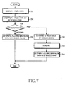
FIG. 7 is a flowchart illustrating a UE operation according to another embodiment of the present invention. The UE is allocated both dedicated and common codes. - Referring to
FIG. 7 , the UE receives Enhanced uplink dedicated channel Relative Grant CHannel (E-RGCH) data containing an RG spread with an orthogonal code every scheduling period instep 702. Instep 704, the UE acquires the RG by interpreting the E-RGCH data first with the dedicated code. The UE then reads the RG instep 706. The RG has the following values listed in Table 6 below.(Table 6) Value Conventional An Embodiment of Present Invention +1 UP UP 0 KEEP Common signaling information -1 DOWN DOWN - If the RG is +1 or -1 in
step 706, the UE increase or decreases an allowed maximum data rate for the E-DCH by a predetermined level instep 708. If the RG is 0, the UE acquires an RG by interpreting the E-RGCH data using the common code instep 710 and reads the RG instep 712. Instep 714, the UE increases, decreases or maintains the allowed maximum data rate for the E-DCH. If the RG is +1, the allowed maximum data rate is increased, if the RG is -1, it is decreased, and if the RG is 0, it is not changed. -
FIG. 8 is a block diagram of a transmitter for transmitting E-RGCH data in the Node B according to the second embodiment of the present invention. - Referring to
FIG. 8 , ascheduler 802 allocates an allowed maximum data rate to a UE that intends to perform an E-DCH service according to a report of the buffer status and power status of the UE and the ROT level of the cell. A signaling scheme is selected according to the allowed maximum data rate. AnRG generator 804 generates an RG set to +1, 0 or -1 by comparing the allocated allowed maximum data rate with the current allowed maximum data rate of the UE. Amodulator 806 modulates the RG. Meanwhile, anRG code controller 814 selects an orthogonal code by which to transmit the RG according to the selected signaling scheme. The orthogonal code is a common code in common signaling and a dedicated code in dedicated signaling. - A
multiplier 808 multiplies the modulated RF by the selected orthogonal code (SRG). Aspreader 810 spreads the product with an E-RGCH channelization code CRG, thereby creating E-RGCH data. AMUX 812 multiplexes the E-RGCH data with other spread channel data, prior to transmission. -
FIG. 9 is a block diagram of a receiver for receiving E-RGCH data in the UE according to the second embodiment of the present invention. - Referring to
FIG. 9 , a received signal is despread with the E-RGCH channelization code (CRG) in adespreader 910, multiplied by the orthogonal code SRG in amultiplier 908, and demodulated in ademodulator 906. AnRG code controller 912 receives both a dedicated and common code of the UE from anE-DCH controller 902. It first provides the dedicated code to themultiplier 908 every scheduling period. Unless an RG interpreted by the dedicated code is "KEEP", theRG code controller 912 provides the common code to themultiplier 908. - An
RG information decider 904 determines whether the RG interpreted by the dedicated code is 0 (KEEP). If the RG is not 0, theRG information decider 904 provides a rate-up or rate-down command based on the RG to theE-DCH controller 902. TheE-DCH controller 902 increase or decreases the current allowed maximum data rate according to the command and selects an E-DCH data rate within the changed allowed maximum data rate. - If the RG has been interpreted by the dedicated code and indicates "KEEP", the
RG information decider 904 requests theRG code controller 912 to set the common code. TheRG code controller 912 correspondingly sets the common code for themultiplier 908. Themultiplier 908 again multiplies the same E-RGCH data by the common code and thedemodulator 906 demodulates the product. Thus, the resulting new RG is provided to theRG information decider 904 and theE-DCH controller 902 increases, maintains or decreases the current allowed maximum data rate according to a decision made on the new RG by theRG information decider 904. - A third embodiment of the present invention is characterized by the use of an indicator indicating a scheduling grant or common control information so that a UE operating in accordance with the first embodiment of the present invention does not need to distinguish the scheduling grant from the common control information by performing a CRC check on an E-SGCH designed for delivering a scheduling grant.
- In the first embodiment of the present invention, the UE uses numerous UE-IDs including dedicated and common UE-IDs in CRC checks. This may bring about reception complexity to the UE which must read a scheduling grant in every TTI. To overcome the shortcoming, an indicator indicating a scheduling grant or common control information is inserted into the header of E-SGCH data, thereby mitigating the CRC check constraint in the third embodiment of the present invention.
- With reference to
FIG. 10 , the structure of E-SGCH data according to the third embodiment of the present invention will be described in great detail. - Referring to
FIG. 10 ,reference numeral 1000 denotes data including a scheduling grant (hereinafter, referred to as scheduling data) andreference numeral 1100 denotes data including common control information (hereinafter, referred to as common control data). Thescheduling data 1000 includes a dedicated or common indicator (D/C) 1002, ascheduling grant 1004, and a CRC with UE-ID 1006. Thecommon control data 1100 includes a D/C 1012,common control information 1014, and a CRC without UE-ID 1016. - The D/
Cs ID 1006 is a CRC masked with a dedicated or common UE-ID. Thecommon control information 1014 is used for the Node B to control the operation of the UE. The CRC without UE-ID 1016 is an ordinary CRC masked with no UE-ID. - In accordance with the third embodiment of the present invention, the UE determines by the D/C of received E-SGCH data whether the
scheduling grant 1004 or thecommon control information 1014 follows the D/C. If the D/C indicates ascheduling grant 1004, the UE performs a CRC check on thescheduling grant 1004 using the CRC with UE-ID 1006. The CRC check is done first using a dedicated UE-ID and then using a common UE-ID. If the D/C indicatescommon control information 1014, the UE performs a CRC check on thecommon control information 1014 using the CRC without UE-ID 1016. In this way, the D/C is interpreted before a CRC check. - The UE then determines an allowed maximum data rate for the E-DCH by interpreting the scheduling grant, or interpreting the common control information.
- In a system where the uplink data rate of a UE is controlled by Node B-controlled scheduling, if a channel for delivering an AG and a channel for delivering an RG are simultaneously established to indicate an E-DCH rate, a scheduler transmits the AG to rapidly increase/decrease the data rate by two or more levels or transmits the RG to increase/decrease the data rate by one level or maintain the data rate.
- The system allocates both dedicated and common UE-IDs to each UE. A Node B transmits an AG using the dedicated or common UE-ID to the UE, when needed.
- An AG delivered by a dedicated UE-ID is constructed in the same format illustrated in Table 3 as in the first embodiment of the present invention. Yet, an AG delivered using a common UE-ID is configured to include an indicator indicating whether an allowed maximum data rate is changed to a data rate indicated by an E-TFI stepwise or at one time.
- Table 7 below illustrates the format of the AG delivered using the common UE-ID.
(Table 7) Name Description E-TFI Allocated rate ALL_UE_indicator Indicates whether AG applies to all UEs or only to some particular UEs. Ramping_indicator Indicates whether to increase to the allocated rate at one time and receive RG or to increase to the allocated rate gradually and not receive RG. - ALL_UE_indicator is defined as
(Table 8) ALL_UE_indicator Description 0 Applies rate only to UEs which did not transmit data in a previous TTI 1 Applies rate to all UEs having common UE-ID - Ramping_indicator is defined as
(Table 9) Ramping_indicator Description 0 increase to the allocated rate at one time and receive RG. 1 increase to the allocated rate gradually and not receive RG. - Upon receipt of an AG using the dedicated UE-ID, the UE operates in the same manner as in the first embodiment of the present invention. On the other hand, if it receives an AG using the common UE-ID, the UE changes its allowed maximum data rate to a data rate indicated by E-TFI stepwise or at one time according to Ramping_indicator. The E-TFI is applied only when data was not transmitted before or all the time according to ALL_UE_indicator.
- Severe interference may be created in the case where a plurality of UEs increase their allowed maximum data rates to target rates indicated by received AGs at one time. Thus UEs, receiving AGs by common UE-IDs, change their allowed maximum data rates to a target rate over a plurality of TTIs according to the Ramping_indicator. However, if an AG received using a common UE-ID indicates a target rate lower than a current allowed maximum data rate, a corresponding UE decreases the allowed maximum data rate to the target rate at one time.
- In the case of a gradual increase to a target rate according to an AG received using a common UE-ID, an RG is meaningless. Therefore, the UE either does not receive an RG or discards a received RG. In the case of receiving an AG using a dedicated UE-ID, the UE increases its allowed maximum data rate to a target rate at one time and then updates the allowed maximum data rate according to an RG received in the next TTI.
- For better understanding of the fourth embodiment of the present invention, a required AG structure and associated operations of a Node B and a UE will be described.
- E-AGCH data containing an AG has the configuration illustrated in
FIG. 3 . The precedingAG 302 indicates an absolute value of an allocated allowed maximum data rate and the following CRC with UE-ID 304 is used to identify a UE for which theAG 302 transmitted on a common channel is destined for a CRC check. Basically, the UE checks errors in theAG 302 using theCRC 304. Since theCRC 304 is masked with a UE-ID, a CRC check by a different UE-ID results in errors. Hence, only the UE having the right UE-ID acquires theAG 302. - The E-AGCH can be configured in two ways to deliver an AG to a UE. The E-AGCH is configured in the above manner, that is, to have a CRC masked with a UE-ID. Thus, the UE performs a CRC check using the CRC. Alternatively, the E-AGCH is configured to have a common CRC and a UE-ID inserted in E-AGCH data. After acquiring error-free E-AGCH data by a CRC check, the UE reads the E-AGCH data and checks a UE-ID.
- As described above, the RNC allocates both dedicated and common UE-IDs to each UE that want to establish an E-DCH by upper layer signaling, with the aim to use common signaling and dedicated signaling in combination. Besides the common and dedicated UE-IDs for scheduling, a common control UE-ID can be additionally allocated to deliver common control information by which the Node B restricts the transmission/reception of the UE.
- The RNC sets the same common UE-ID for all UEs in each cell or for a UE group classified by service type. UEs that report similar status information, have the same QoS, or have the same service type can be grouped into one UE group.
- In every scheduling period, a Node B scheduler determines an AG and a signaling scheme for each UE. The signaling scheme is determined depending on system design and implementation. In one embodiment, the Node B selects common signaling to transmit an AG, if the number of UEs to which the same AG is applied in a cell is equal to or greater than a predetermined value. It can be further contemplated as another embodiment that the Node B allocates the same AG to a predetermined UE group and decides to transmit the AG to the UE group by a common UE-ID. If the load of a cell is small and a small number of UEs are scheduled, the Node B may transmit an AG to all the UEs within the cell by a common UE-ID. Once an AG and a signaling scheme are determined, the Node B transmits the AG together with a CRC masked with a dedicated or common UE-ID to the UE.
-
FIG. 11 is a flowchart illustrating a UE operation according to a fourth embodiment of the present invention. - Referring to
FIG. 11 , the UE receives E-AGCH data every scheduling period instep 1102. The UE performs a CRC check on the E-AGCH data first using a common control UE-ID in step 1104 and determines whether the CRC check has passed instep 1106. If the CRC check is good, this implies that the E-AGCH data contains common control information. Thus, the UE interprets the common control information instep 1108. - If the common control information is transmission restriction information indicating a one-level rate-down or a change to a minimum rate, the UE restricts an E-DCH data rate according to the common control information in
step 1112. In this case, the UE does not attempt to receive an AG by a dedicated UE-ID or a common UE-ID. However, if the CRC check has failed instep 1106 or if the common control information is not related to transmission restriction, for example, it is a rate request instep 1108, the UE performs a CRC check on the E-AGCH data using the dedicated UE-ID instep 1110. - If determining that an AG transmitted using the dedicated UE-ID exists as a result of the CRC check in
step 1114, the UE updates its allowed maximum data rate for the E-DCH to a data rate indicated by the AG instep 1116 and sets an RG reception mode to ON to receive an RG in the next TTI instep 1126. On the contrary, if the CRC check has failed, that is, the AG transmitted by the dedicated UE-ID is not present instep 1114, the UE performs a CRC check on the E-AGCH data using the common UE-ID instep 1118. When the CRC check is good and thus an AG is acquired instep 1120, the UE updates the allowed maximum data rate according to the AG instep 1122 and sets an RG reception mode to OFF not to receive an RG in the next TTI instep 1128. - To describe
step 1122 in great detail, the UE reads ALL_UE_indicator included in the AG instep 1122. If ALL_UE_indicator is 1, this implies that the AG applies to all UEs. Thus, the UE updates the allowed maximum data rate to the data rate indicated by the AG (referred to as RATE_AG) and proceeds to step 1128. On the other hand, ALL_UE_indicator is 0, the UE determines whether it transmitted data in a previous TTI. If the UE did not transmit data in a previous TTI, it updates the allowed maximum data rate to RATE_AG and proceeds to step 1128. While not shown, if the UE transmitted data in a previous TTI, it maintains the previous allowed maximum data rate. - If the allowed maximum data rate is increased in
step 1122, the UE reads Ramping_indicator included in the AG. If Ramping_indicator is 0, the UE increases the allowed maximum data rate at one time to the data rate indicated by E-TFI included in the AG. If Ramping_indicator is 1, the UE increases the allowed maximum data rate stepwise to the indicated data rate. - Meanwhile, if the CRC check has failed in
step 1120, this implies that the AG based on the common UE-ID was not transmitted. Thus the UE maintains the previous allowed maximum data rate instep 1124. In this case, no AGs have been received and thus the UE receives an RG for rate determination. - With reference to
FIG. 12 , a description will be made of a method of determining an actual uplink data rate in the UE after updating its allowed maximum data rate in the procedure illustrated inFIG. 11 . - Referring to
FIG. 12 , upon generation of E-DCH data to be transmitted instep 1202, the UE determines whether the current allowed maximum data rate was updated using the dedicated or common UE-ID instep 1204. If the current allowed maximum data rate was updated using the dedicated UE-ID, the UE selects a final data rate within the updated allowed maximum data rate based on the amount of data to be transmitted and the status information of the UE. If a large amount of data is to be transmitted and sufficient transmit power is available, the UE can transmit the data at the allowed maximum data rate. - While not shown, if the current allowed maximum data rate was updated using the common UE-ID, the UE reads Ramping_indicator in an AG using the common UE-ID. If Ramping_indicator is 0, the UE goes to step 1206. If Ramping_indicator is 1, the UE changes the previous data rate by a predetermined value, delta and compares the changed data rate with the current allowed maximum data rate in
step 1208. The value, delta is a maximum rate increment/decrement available in one TTI, set by upper signaling or predetermined. If the changed data rate is lower than the allowed maximum data rate, the UE selects a final data rate within the changed data rate based on the amount of data to be transmitted and the UE status information (such as a power margin) instep 1210. If the changed data rate is equal to or higher than the allowed maximum data rate, the UE selects a final data rate within the allowed maximum data rate based on the amount of data to be transmitted and the UE status information (such as a power margin) instep 1212. - A Node B transmitter for transmitting an AG and a UE receiver for receiving the AG are identical in configuration and operation to their counterparts that operate according to the first embodiment of the present invention. Thus, they will not be described redundantly herein.
- In a system that controls the uplink data rate of a UE by Node B-controlled scheduling, the UE has a fast ramping UE-ID and a slow ramping UE-ID to receive an AG. The fast and slow ramping UE-IDs are transmitted by dedicated or common signaling. The UE may have an additional common control UE-ID. A Node B simultaneously establishes a channel for delivering an AG and a channel for delivering an RG, for scheduling of uplink packet data transmission.
- Upon receipt of an AG by the fast ramping UE-ID, the UE increases its allowed maximum data rate to a target rate at one time and receives an RG. Upon receipt of an AG by the slow ramping UE-ID, the UE increases its allowed maximum data rate to a target rate stepwise and does not receive an RG. Because of the stepwise rate increase, the RG is meaningless to the UE. Therefore, when receiving the AG by the slow ramping UE-ID, the UE neither receives an RG nor discards a received RG. On the other hand, when receiving the AG by the fast ramping UE-ID, the UE increases the allowed maximum data rate to the target rate and then receives an RG in the next TTI, for E-DCH transmission.
- At the start of E-DCH communications from the UE, the RNC allocates both a fast ramping UE-ID and a slow ramping UE-ID to the UE by upper layer signaling, taking into account many factors including Node B-controlled scheduling and the E-DCH service type of the UE. The UE-ID allocation can be considered in the following ways:
- (1) The RNC allocates a fast ramping UE-ID to each UE and a slow ramping UE-ID to each UE group. In this case, the Node B and the UE operate in the same manner as in the fourth embodiment of the present invention.
- (2) The RNC allocates a fast ramping UE-ID and a slow ramping UE-ID to each UE group.
- (3) The RNC allocates a fast ramping UE-ID and a slow ramping UE-ID to each UE.
- (4) The RNC allocates a fast ramping UE-ID to each UE group and a slow ramping UE-ID to each UE. UEs which report similar UE status information, have the same QoS, or the same service type are grouped into one UE group.
- Table 10 below illustrates UE-IDs used in the fifth embodiment of the present invention.
(Table 10) ID Type Information included in E-AGCH Description Fast ramping UE-ID ramping AG -Increase allowed maximum data rate to target rate at one time -receive an RG Slow ramping UE-ID AG -Increase allowed maximum data rate to target rate stepwise -does not receive an RG Common Control UE-ID Common control information Node B controls UEs with common control ID -
FIG. 13 is a flowchart illustrating a UE operation according to the fifth embodiment of the present invention. The UE has all of a fast ramping UE-ID, a slow ramping UE-ID, and a common control UE-ID and operates depending on the UE-ID type of a received AG. - Referring to
FIG. 13 , the UE receives E-AGCH data every scheduling period instep 1302. The UE performs a CRC check on the E-AGCH data first using a common control UE-ID instep 1304 and determines whether the CRC check has passed instep 1306. If the CRC check is good, this implies that the E-AGCH data contains common control information. Thus, the UE interprets the common control information instep 1308. - If the common control information is transmission restriction information indicating a one-level rate-down or a change to a minimum rate, the UE restricts an E-DCH data rate according to the common control information in
step 1312. In this case, the UE does not attempt to receive an AG by the fast or slow ramping UE-ID. However, if the CRC check has failed instep 1306 or if the common control information is not related to transmission restriction, for example, it is a rate request instep 1308, the UE performs a CRC check on the E-AGCH data using the fast ramping UE-ID instep 1310. - If determining that an AG transmitted using the fast ramping UE-ID exists as a result of the CRC check in
step 1314, the UE updates its allowed maximum data rate for the E-DCH to a data rate indicated by the AG instep 1316 and sets an RG reception mode to ON to receive an RG in the next TTI instep 1326. On the contrary, if the CRC check has failed, that is, the AG transmitted by the dedicated UE-ID is not present instep 1314, the UE performs a CRC check on the E-AGCH data using the slow ramping UE-ID instep 1318. - When the CRC check is good and thus an AG is acquired in
step 1320, the UE updates the allowed maximum data rate according to the AG instep 1322 and sets an RG reception mode to OFF not to receive an RG in the next TTI or to ignore a received RG in the next TTI instep 1328. Meanwhile, if the CRC check has failed instep 1320, this implies that the AG based on the slow ramping UE-ID was not transmitted. Thus the UE maintains the previous allowed maximum data rate instep 1324. In this case, no AGs have been received and thus the UE receives an RG for rate determination. - After setting the allowed maximum data rate in the above procedure, the UE selects a final data rate for actual data transmission in the procedure illustrated in
FIG. 12 . - In accordance with the fifth embodiment of the present invention, the Node B is configured and operates similarly to in the first embodiment of the present invention. With reference to
FIG. 5 , the operation of the Node B according to the fifth embodiment of the present invention will be described below. - Referring to
FIG. 5 , theNode B scheduler 502 preserves fast ramping UE-IDs and slow ramping UE-IDs allocated by the RNC, for use in scheduling uplink data transmission. Thescheduler 502 allocates an allowed maximum data rate to a UE that intends to perform an E-DCH service according to a report of the buffer status and power status of the UE and the ROT level of the cell. Thescheduler 502 further determines a UE-ID by which to notify the UE of the allowed maximum data rate. To allow the UE to receive an RG, thescheduler 502 provides a fast ramping UE-ID to theCRC generator 504. To prevent the UE from receiving an RG, thescheduler 502 provides a slow ramping UE-ID to theCRC generator 504. Based on any other criterion, thescheduler 502 can select the fast or slow ramping UE-ID. - The
rate information generator 506 generates an AG according to the allowed maximum data rate and theCRC generator 504 generates a CRC masked with the fast or slow ramping UE-ID with respect to the AG. TheCRC adder 508 adds the masked CRC to the AG. Since the masked CRC contains the UE-ID, it is called a UE-ID-specific CRC. The masked CRC and the AG are encoded in theencoder 510 and modulated in themodulator 512. The modulated data is spread with an E-AGCH channelization code CAG in thespreader 514. TheMUX 516 multiplexes the spread E-AGCH data with other spread channel data, prior to transmission. - While not shown, the Node B generates an RG indicating a change in the allowed maximum data rate decided by the
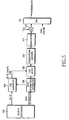
Node B scheduler 502, modulates the RG, and transmits the RG using an orthogonal code allocated to the UE and an E-RGCH channelization code. -
FIG. 14 is a block diagram of a receiver for receiving E-AGCH data and E-RGCH data in the UE according to the fifth embodiment of the present invention. A configuration for receiving common control information by a common control UE-ID is excluded from the illustrated receiver configuration. - Referring to
FIG. 14 , a received signal is despread with the E-AGCH channelization code CAG in adespreader 1402, demodulated in ademodulator 1404, and decoded in adecoder 1406. ACRC detector 1408 extracts a masked CRC from the decoded data. AnE-DCH controller 1412 manages a fast ramping UE-ID and a slow ramping UE-ID allocated by the RNC for scheduling of uplink data transmission. ACRC checker 1414 receives both the fast and slow ramping UE-IDs from theE-DCH controller 1412 and first performs a CRC check on the decoded data by demasking the masked CRC using the fast ramping UE-ID. If the CRC has failed, theCRC checker 1414 performs a CRC check on the decoded data by demasking the masked CRC using the slow ramping UE-ID. - The
CRC checker 1414 provides the CRC results to theCRC detector 1408. If at least one of the UE-IDs has passed in the CRC check, theCRC detector 1414 provides an AG without the masked CRC in the decoded data to arate information decider 1410. If both the UE-IDs have failed in the CRC check, theCRC detector 1414 discards the decoded data. TheCRC detector 1408 provides therate information decider 1410 with ID information indicating whether the AG has been interpreted by the fast or slow ramping UE-ID. Therate information decider 1410 updates the allowed maximum data rate of the UE using the AG according to the ID information, and provides the updated allowed maximum data rate to theE-DCH controller 1412, for E-DCH transmission. - Meanwhile, the ID information is also provided to the
E-DCH controller 1412. TheE-DCH controller 1412 determines whether to receive an RG depending on the ID information. If the received AG is associated with the fast ramping UE-ID, theE-DCH controller 1412 sets an RG reception mode to ON. If the received AG is associated with the slow ramping UE-ID, theE-DCH controller 1412 sets the RG reception mode to OFF. The RG reception mode is notified to anRG reception controller 1430. - The
RG reception controller 1430 controls a firstRG reception switch 1418 according to the RG reception mode. The firstRG reception switch 1418 provides a received signal to thedespreader 1420 only when the RG reception mode is ON. Thedespreader 1420 despreads the signal with an E-RGCH channelization code CRG. The despread signal is multiplied by an orthogonal code SRG allocated to the UE in amultiplier 1422 and demodulated in ademodulator 1424. - An
RG information decider 1426 determines whether the RG received from thedemodulator 1424 is 0 (KEEP). If the RG is not 0, theRG information decider 1426 provides a rate-increase or rate-decrease command according to the RG to theE-DCH controller 1412 through a secondRG reception switch 1428. Similarly to the first RG reception switch 1614, the secondRG reception switch 1428 provides the command to theE-DCH controller 1412 only when the RG reception mode is ON. When not receiving an allowed maximum data rate from therate information decider 1410, theE-DCH controller 1412 increases or decreases a stored allowed maximum data rate according to the command and selects an E-DCH rate within the changed allowed maximum data rate. - In accordance with the embodiments of present invention as described above, an AG and an RG are efficiently transmitted for an uplink packet data service. Therefore, downlink signaling overhead arising from notifying a UE of an allocated allowed maximum data rate is reduced and interference from signaling AGs is minimized.
- While the invention has been shown and described with reference to certain embodiments thereof, it will be understood by those skilled in the art that various changes in form and details may be made therein without departing from the scope of the invention as defined by the appended claims.
Claims (28)
- A method of scheduling uplink data transmission for user equipment UE (101, 102), in a mobile communication system supporting an uplink packet data service, characterized by the steps of:receiving (402) from a Node B, an absolute grant, AG, indicating the absolute value of an allowed maximum data rate for uplink data transmission;determining whether the AG has a pre-assigned first or second UE-Identifier, ID,receiving from the Node B, a relative grant, RG, indicating a change in the allowed maximum data rate for uplink data transmission, if the AG has the first UE-ID;neglecting the RG received from the Node B, if the AG has the second UE-ID; andtransmitting uplink data within an allowed maximum data rate decided by one of the AG and the RG.
- The method of claim 1, further comprising the step of, changing, at one time, the allowed maximum data rate to a target data rate indicated by the AG, if the AG has the first UE-ID.
- The method of claim 1, further comprising the step of, changing, stepwise in each transmission time interval, the allowed maximum data rate to a target data rate indicated by the AG, if the AG has the second UE-ID.
- The method of claim 1, wherein the first UE-ID is unique to the UE and the second UE-ID is unique to a predetermined UE group that comprises the UE.
- The method of claim 1, wherein the first UE-ID and the second UE-ID are unique to a predetermined UE group comprising the UE.
- The method of claim 1, wherein the first UE-ID and the second UE-ID are unique to the UE.
- The method of claim 1, wherein the determining step comprises the steps of:detecting a masked cyclic redundancy check, CRC, attached to the AG;demasking the masked CRC with the first UE-ID,performing a CRC check on the AG using the CRC demasked with the first UE-ID;determining that the AG has the first UE-ID, if the CRC check using the first UE-ID is good;demasking the masked CRC with the second UE-ID, if the CRC check using the first UE-ID fails;performing a CRC check on the AG using the CRC demasked with the second UE-ID; anddetermining that the AG has the second UE-ID, if the CRC check using the second UE-ID is good.
- An apparatus for scheduling uplink data transmission for user equipment, UE, in a mobile communication system supporting an uplink packet data service, characterized by:an absolute grant, AG, receiver for receiving from a Node B, an AG indicating the absolute value of an allowed maximum data rate for uplink data transmission;a controller for managing a pre-assigned first and second UE-Identifiers, UE-IDs, setting a relative grant, RG, reception mode to ON if the AG has the first UE-ID and the RG reception mode to OFF if the AG has the second UE-ID, and determining the allowed maximum data rate for uplink data transmission according to the one of AG and RG; andan RG receiver for receiving an RG from the Node B, when the RG reception mode is set to ON.
- The apparatus of claim 8, wherein the controller is further for changing, at one time, the allowed maximum data rate to a target data rate indicated by the AG, if the AG has the first UE-ID.
- The apparatus of claim 8, wherein the controller is further for changing, stepwise in each transmission time interval, the allowed maximum data rate to a target data rate indicated by the AG, if the AG has the second UE-ID.
- The apparatus of claim 8, wherein the first UE-ID is unique to the UE and the second UE-ID is unique to a predetermined UE group that comprises the UE.
- The apparatus of claim 8, wherein the first UE-ID and the second UE-ID are unique to a predetermined UE group that comprises the UE.
- The apparatus of claim 8, wherein the first UE-ID and the second UE-ID are unique to the UE.
- The apparatus of claim 8, wherein the decider comprises:a cyclic redundancy check, CRC, detector for detecting a masked CRC attached to the AG; anda CRC checker for demasking the masked CRC with the first UE-ID, performing a CRC check on the AG using the CRC demasked with the first UE-ID, determining that the AG has the first UE-ID, if the CRC check is good, demasking the masked CRC with the second UE-ID, if the CRC check fails, performing a CRC check on the AG using the CRC demasked with the second UE-ID, and determining that the AG has the second UE-ID, if the CRC check is good.
- A method of scheduling uplink data transmission for user equipment, UE, in a Node B of a mobile communication system supporting an uplink packet data service, characterized by the steps of:allocating a first LJE-Identifier, UE-ID and a second UE-ID for scheduling uplink data transmission;determining an allowed maximum data rate for the UE, selecting one of the first or second UE-IDs to notify the UE of the allowed maximum data rate, the first UE-ID indicating reception of a relative grant, RG, indicating a change in the allowed maximum data rate and the second UE-ID indicating non-reception of the RG;generating an absolute grant, AG, indicating the allowed maximum data rate and adding the selected IJE-ID to the AG; andtransmitting the AG with the selected UE-ID to the UE.
- The method of claim 15, wherein the first UE-ID indicates that the UE is to change, at one time, the allowed maximum data rate to a target data rate indicated by an AG having the first UE-ID.
- The method of claim 15, wherein the second UE-ID indicates that the UE is to change, stepwise in each transmission time interval, the allowed maximum data rate to a target data rate indicated by an AG having first UE-ID.
- The method of claim 15, wherein the first UE-ID is unique to the UE and the second UE-ID is unique to a predetermined UE group comprising the UE.
- The method of claim 15, wherein the first UE-ID and the second UE-ID are unique to a predetermined UE group comprising the UE.
- The method of claim 15, wherein the first UE-ID and the second UE-ID are unique to the UE.
- The method of claim 15, wherein the adding step comprises the steps of:generating a cyclic redundancy check, CRC, for the AG;masking the CRC with the selected UE-ID; andadding the masked CRC to the AG.
- An apparatus for scheduling uplink data transmission for user equipment, UE, in a Node B of a mobile communication system supporting an uplink packet data service, characterized by:a scheduler adapted to manage first and second UE-Identifiers, UE-IDs, allocated for scheduling of uplink data transmission, adapted to determine an allowed maximum data rate for the UE and adapted to select one of the first or second UE-IDs to notify the UE of the allowed maximum data rate, the first UE-ID indicating reception of a relative grant, RG, indicating a change in the allowed maximum data rate and the second UE-ID indicating non-reception of the RG;a rate information generator for generating an absolute grant, AG, indicating the allowed maximum data rate;an adder for adding the selected UE-ID to the AG;a first transmitter for transmitting the AG with the selected UE-ID to the UE; anda second transmitter for transmitting the RG to the UE.
- The apparatus of claim 22, wherein an AG with the first UE-ID selected indicates that the UE is to change, at one time, the allowed maximum data rate to a target data rate.
- The apparatus of claim 22, wherein an AG with the second UE-ID selected indicates that the UE is to change, stepwise in each transmission time interval, the allowed maximum data rate to a target data rate.
- The apparatus of claim 22, wherein the first UE-ID is unique to the UE and the second UE-ID is unique to a predetermined UE group comprising the UE.
- The apparatus of claim 22, wherein the first UE-ID and the second UE-ID are unique to a predetermined UE group comprising the UE.
- The apparatus of claim 22, wherein the first UE-ID and the second UE-ID are unique to the UE.
- The apparatus of claim 22, wherein the adder comprises:a cyclic redundancy check, CRC, generator for generating a CRC for the AG and masking the CRC with the selected UE-ID; anda CRC adder for adding the masked CRC to the AG.
Priority Applications (1)
| Application Number | Priority Date | Filing Date | Title |
|---|---|---|---|
| EP20080003812 EP1921812B1 (en) | 2004-11-05 | 2005-11-04 | Method and apparatus for scheduling data transmission in a mobile communication system supporting packet data service |
Applications Claiming Priority (3)
| Application Number | Priority Date | Filing Date | Title |
|---|---|---|---|
| KR20040090043 | 2004-11-05 | ||
| KR20040091119 | 2004-11-09 | ||
| KR20040092963 | 2004-11-15 |
Related Child Applications (1)
| Application Number | Title | Priority Date | Filing Date |
|---|---|---|---|
| EP20080003812 Division EP1921812B1 (en) | 2004-11-05 | 2005-11-04 | Method and apparatus for scheduling data transmission in a mobile communication system supporting packet data service |
Publications (2)
| Publication Number | Publication Date |
|---|---|
| EP1655909A1 EP1655909A1 (en) | 2006-05-10 |
| EP1655909B1 true EP1655909B1 (en) | 2008-04-16 |
Family
ID=35734903
Family Applications (2)
| Application Number | Title | Priority Date | Filing Date |
|---|---|---|---|
| EP20080003812 Active EP1921812B1 (en) | 2004-11-05 | 2005-11-04 | Method and apparatus for scheduling data transmission in a mobile communication system supporting packet data service |
| EP20050024127 Active EP1655909B1 (en) | 2004-11-05 | 2005-11-04 | Method and apparatus for scheduling uplink data transmission using different UE-IDs in a mobile communication system supporting uplink packet data service |
Family Applications Before (1)
| Application Number | Title | Priority Date | Filing Date |
|---|---|---|---|
| EP20080003812 Active EP1921812B1 (en) | 2004-11-05 | 2005-11-04 | Method and apparatus for scheduling data transmission in a mobile communication system supporting packet data service |
Country Status (7)
| Country | Link |
|---|---|
| US (1) | US7480269B2 (en) |
| EP (2) | EP1921812B1 (en) |
| JP (2) | JP2006135992A (en) |
| KR (1) | KR100651548B1 (en) |
| CN (2) | CN101854675B (en) |
| AU (1) | AU2005229703B2 (en) |
| DE (1) | DE602005006072T2 (en) |
Cited By (1)
| Publication number | Priority date | Publication date | Assignee | Title |
|---|---|---|---|---|
| CN109314976A (en) * | 2016-06-29 | 2019-02-05 | 华为技术有限公司 | A kind of data transmission method and device |
Families Citing this family (77)
| Publication number | Priority date | Publication date | Assignee | Title |
|---|---|---|---|---|
| US7046678B2 (en) * | 2000-02-18 | 2006-05-16 | At & T Corp. | Channel efficiency based packet scheduling for interactive data in cellular networks |
| US7684408B2 (en) * | 2003-09-30 | 2010-03-23 | Mitsubishi Denki Kabushiki Kaisha | Communication mode control method, mobile communication system, base station control apparatus, base station, and mobile communication terminal |
| EP1845746B1 (en) * | 2005-01-05 | 2009-12-02 | NTT DoCoMo Inc. | Transmission rate control method, radio base station, and radio network controller |
| JP4083771B2 (en) * | 2005-02-09 | 2008-04-30 | 株式会社エヌ・ティ・ティ・ドコモ | Radio resource management method, radio network controller and radio base station |
| US7693537B2 (en) * | 2005-03-22 | 2010-04-06 | Ntt Docomo, Inc. | Transmission rate control method, transmission rate control system, and mobile station |
| EP1876744A4 (en) * | 2005-04-04 | 2012-11-21 | Ntt Docomo Inc | Transmitting method, receiving method, radio base station, and mobile station |
| JP4559290B2 (en) | 2005-04-28 | 2010-10-06 | 株式会社エヌ・ティ・ティ・ドコモ | Transmission rate control method, mobile station and radio base station |
| JP4616070B2 (en) * | 2005-05-02 | 2011-01-19 | 株式会社エヌ・ティ・ティ・ドコモ | Transmission rate control method and mobile station |
| GB0509162D0 (en) * | 2005-05-04 | 2005-06-15 | Koninkl Philips Electronics Nv | Method of operating a radio terminal |
| JP4751673B2 (en) * | 2005-08-29 | 2011-08-17 | 株式会社エヌ・ティ・ティ・ドコモ | Transmission rate control method and mobile station |
| US7613157B2 (en) * | 2005-08-30 | 2009-11-03 | Interdigital Technology Corporation | Wireless communication method and apparatus for processing enhanced uplink scheduling grants |
| US7688796B2 (en) * | 2005-08-31 | 2010-03-30 | Interdigital Technology Corporation | Wireless communication method and apparatus for decoding enhanced dedicated channel absolute grant channel transmissions |
| US7801487B2 (en) * | 2005-12-29 | 2010-09-21 | Airvana, Inc. | Detection of radio frequency interference in wireless communication systems |
| US7660279B2 (en) * | 2006-01-27 | 2010-02-09 | Alcatel-Lucent Usa Inc. | Method of scheduling uplink resource in a wireless communication system |
| ES2721056T3 (en) * | 2006-02-24 | 2019-07-26 | Sun Patent Trust | Candidate selection technique for resource blocks that uses packet programming in wireless communication systems |
| WO2007108636A1 (en) * | 2006-03-20 | 2007-09-27 | Samsung Electronics Co., Ltd. | Method and apparatus for allocating and identifying frequency resources in a frequency division multiple access system |
| US7693156B2 (en) * | 2006-04-19 | 2010-04-06 | Nokia Corporation | Apparatus, method and computer program product providing user equipment operation by considering scheduling information with regard to the use of relative grants |
| US20070297361A1 (en) * | 2006-06-15 | 2007-12-27 | Ranta-Aho Karri | Apparatus, method and software product for utilizing user equipment identification to add signaling information on a shared control channel |
| KR101297564B1 (en) * | 2006-07-06 | 2013-09-17 | 광동 누프론트 컴퓨터 시스템 칩 컴퍼니 리미티드 | Wireless communication method of selecting an enhanced uplink transport format combination by setting a scheduling grant payload to the highest payload that can be transmitted |
| WO2008069617A2 (en) * | 2006-12-07 | 2008-06-12 | Lg Electronics Inc. | Method and transmitter for transmitting and method of receiving status report and structure of status data blocks in a mobile communication system |
| KR101342365B1 (en) * | 2006-12-07 | 2013-12-16 | 엘지전자 주식회사 | Method of transferring data in wireless communication system |
| WO2008069616A2 (en) | 2006-12-07 | 2008-06-12 | Lg Electronics Inc. | Methods of transferring data in a wireless communication system |
| TWI486081B (en) * | 2006-12-28 | 2015-05-21 | Interdigital Tech Corp | Efficient uplink operation with high instantaneous data rates |
| WO2008085954A2 (en) | 2007-01-05 | 2008-07-17 | Interdigital Technology Corporation | Fast uplink response to downlink shared channel transmission without a dedicated uplink channel |
| EP2100392A4 (en) * | 2007-01-08 | 2013-09-25 | Lg Electronics Inc | Method for receiving common channel in wireless communication and terminal thereof |
| WO2008084984A2 (en) * | 2007-01-09 | 2008-07-17 | Lg Electronics Inc. | Method of controlling data retransmission in a wireless communication system |
| WO2008084985A2 (en) * | 2007-01-09 | 2008-07-17 | Lg Electronics Inc. | Method of transmitting and receiving data in a wireless communication system |
| CN104883745B (en) | 2007-01-09 | 2019-06-14 | 华为技术有限公司 | Base station apparatus, mobile station apparatus, control method for sending information, control message receiving method and program |
| EP2103071A4 (en) * | 2007-01-09 | 2013-07-31 | Lg Electronics Inc | Method of transmitting and receiving scheduling information in a wireless communication system |
| CN101578783A (en) * | 2007-01-10 | 2009-11-11 | Lg电子株式会社 | Method for constructing data format in mobile communication and terminal thereof |
| KR101211758B1 (en) * | 2007-01-10 | 2012-12-12 | 엘지전자 주식회사 | Method for generating block data in wireless communication system |
| EP2176961A2 (en) * | 2007-08-10 | 2010-04-21 | Samsung Electronics Co., Ltd. | Apparatus and method for controlling uplink dedicated channel in a mobile communication system |
| EP3024294B1 (en) | 2007-08-22 | 2018-06-06 | LG Electronics, Inc. | Allocating radio resources in a wireless communication system |
| USRE44767E1 (en) | 2007-08-22 | 2014-02-18 | Lg Electronics Inc. | Method of allocating radio resources in a wireless communication system |
| CN114501691A (en) | 2007-09-28 | 2022-05-13 | 泛泰有限责任公司 | Method executed by WTRU, method executed by base station and base station |
| CN101400140B (en) * | 2007-09-30 | 2010-06-02 | 大唐移动通信设备有限公司 | Method and apparatus for lowering cost of uplink scheduling control signaling |
| KR101364797B1 (en) | 2007-10-02 | 2014-02-19 | 엘지전자 주식회사 | Method for allocating uplink radio resource |
| KR101568149B1 (en) | 2007-10-25 | 2015-11-11 | 시그널 트러스트 포 와이어리스 이노베이션 | Methods and apparatuses for management and setup of enhanced mac-e/es resources in cell-fach state |
| CN101426254B (en) * | 2007-10-31 | 2010-12-08 | 华为技术有限公司 | Method, apparatus and system for information transmission implementation |
| CN101426253B (en) * | 2007-10-31 | 2013-08-07 | 华为技术有限公司 | Method, apparatus and system for information transmission implementation |
| US9215669B2 (en) * | 2007-11-16 | 2015-12-15 | Qualcomm Incorporated | Preamble design for a wireless signal |
| US8918112B2 (en) | 2007-11-16 | 2014-12-23 | Qualcomm Incorporated | Preamble design for a wireless signal |
| US20090129333A1 (en) * | 2007-11-16 | 2009-05-21 | Qualcomm Incorporated | Preamble design for a wireless signal |
| US9264976B2 (en) * | 2007-11-16 | 2016-02-16 | Qualcomm Incorporated | Preamble design for a wireless signal |
| JP5113500B2 (en) | 2007-11-26 | 2013-01-09 | 株式会社エヌ・ティ・ティ・ドコモ | Transmission rate control method and radio base station |
| JP5117837B2 (en) * | 2007-12-07 | 2013-01-16 | 株式会社エヌ・ティ・ティ・ドコモ | Wireless communication system, wireless communication method, and base station |
| WO2009079812A1 (en) * | 2007-12-10 | 2009-07-02 | Zte Corporation | A method of configuring the absolute grant mapping table for base station |
| AU2008341208B2 (en) * | 2007-12-21 | 2013-07-18 | Telefonaktiebolaget L M Ericsson (Publ) | Methods and arrangements in a mobile telecommunications network |
| BRPI0722340A2 (en) * | 2007-12-21 | 2014-07-01 | Ericsson Telefon Ab L M | METHOD FOR OPERATING THE HIGH SPEED UP LINK STATION AND HIGH SPEED UP LINK STATION. |
| WO2009088877A2 (en) | 2008-01-02 | 2009-07-16 | Interdigital Patent Holdings, Inc. | Methods and apparatus for cell reselection |
| CN101217298B (en) * | 2008-01-03 | 2011-08-24 | 中兴通讯股份有限公司 | A method to reduce and enhance the code rate of absolute authorization channel of private channel |
| US10051658B2 (en) | 2008-01-07 | 2018-08-14 | Samsung Electronics Co., Ltd | Apparatus and method for transmitting and receiving enhanced RACH in a mobile communication system |
| CN101911813B (en) * | 2008-01-07 | 2015-06-03 | 三星电子株式会社 | Apparatus and method for transmitting and receiving enhanced RACH in a mobile communication system |
| US9801188B2 (en) * | 2008-02-01 | 2017-10-24 | Qualcomm Incorporated | Backhaul signaling for interference avoidance |
| KR101577845B1 (en) | 2008-02-04 | 2015-12-15 | 텔레폰악티에볼라겟엘엠에릭슨(펍) | Methods and arrangements for a mobile communications network |
| US20090201871A1 (en) * | 2008-02-12 | 2009-08-13 | Qualcomm, Incorporated | Efficient utilization of channel resources in wireless communication |
| US8768372B2 (en) | 2008-02-13 | 2014-07-01 | Qualcomm Incorporated | Sector interference management based on inter-sector performance |
| JP5184141B2 (en) * | 2008-02-25 | 2013-04-17 | 株式会社エヌ・ティ・ティ・ドコモ | Wireless communication system, wireless communication method, and base station |
| JP5081706B2 (en) * | 2008-02-25 | 2012-11-28 | 株式会社エヌ・ティ・ティ・ドコモ | Mobile communication method, mobile communication system, and radio base station |
| JPWO2010029763A1 (en) * | 2008-09-12 | 2012-02-02 | パナソニック株式会社 | Relay device and relay method |
| US20110173519A1 (en) * | 2008-09-12 | 2011-07-14 | Panasonic Corporation | Wireless communication apparatus and error detection result feedback method |
| US8380178B1 (en) | 2009-04-03 | 2013-02-19 | Sprint Communications Company L.P. | Presenting an indication of an originating carrier of a wireless call |
| JP5293423B2 (en) * | 2009-06-05 | 2013-09-18 | 富士通株式会社 | Terminal apparatus and base station apparatus |
| US8150446B2 (en) * | 2009-06-17 | 2012-04-03 | Telefonaktiebolaget L M Ericsson (Publ) | Thermal energy control in a mobile transceiver |
| US20110038334A1 (en) * | 2009-08-12 | 2011-02-17 | Qualcomm Incorporated | Method and apparatus for semi-persistent scheduling for multiple uplink voip connections |
| EP2537386B1 (en) * | 2010-02-15 | 2019-09-18 | Telefonaktiebolaget LM Ericsson (publ) | Contention based access optimization |
| US9277532B2 (en) * | 2012-09-18 | 2016-03-01 | Alcatel Lucent | Methods for allocating and scheduling uplink and downlink transmissions and apparatuses thereof |
| US8902907B2 (en) * | 2012-10-05 | 2014-12-02 | Futurewei Technologies, Inc. | Terminal based grouping virtual transmission and reception in wireless networks |
| US10390333B2 (en) * | 2013-05-02 | 2019-08-20 | Huawei Technologies Co., Ltd. | System and method for transmission source identification |
| CN105359610B (en) * | 2013-05-08 | 2020-10-16 | 诺基亚技术有限公司 | Signaling optimization of absolute grants for uplink transmission using time division multiplexing |
| US20140376459A1 (en) * | 2013-06-21 | 2014-12-25 | Qualcomm Incorporated | Aggregating data to improve performance at a user equipment (ue) |
| JP6159035B2 (en) | 2014-04-01 | 2017-07-05 | テレフオンアクチーボラゲット エルエム エリクソン(パブル) | Method and node for controlling uplink transmission |
| US11595164B2 (en) | 2016-09-30 | 2023-02-28 | Huawei Technologies Co., Ltd. | Self-contained subframe configuration method and apparatus |
| US10277252B2 (en) | 2017-01-09 | 2019-04-30 | At&T Intellectual Property I, L.P. | Encoding data with polar codes for control channels |
| CN106940312B (en) * | 2017-01-25 | 2019-08-06 | 北京镧彩科技有限公司 | A kind of adjustable off-color material of dynamics and preparation method thereof |
| US10856300B2 (en) * | 2017-10-17 | 2020-12-01 | Qualcomm Incorporated | Per-TTI rank control within transmission opportunity for downlink comp |
| US10764907B2 (en) * | 2017-12-29 | 2020-09-01 | Futurewei Technologies, Inc. | Scheduling of data transmission from internet of things user equipment to a base station of a cellular network |
Family Cites Families (10)
| Publication number | Priority date | Publication date | Assignee | Title |
|---|---|---|---|---|
| EP1190496B1 (en) * | 2000-02-17 | 2004-10-27 | Samsung Electronics Co., Ltd. | Apparatus and method for assigning a common packet channel in a cdma communication system |
| US6804528B1 (en) * | 2000-11-03 | 2004-10-12 | Lucent Technologies, Inc. | Apparatus and method for use in the multicast of traffic data in wireless multiple access communications systems |
| KR100396669B1 (en) * | 2001-05-04 | 2003-09-02 | 엘지전자 주식회사 | Method for controling the data rate of reverse link, Terminal for the same |
| US6915473B2 (en) * | 2001-05-14 | 2005-07-05 | Interdigital Technology Corporation | Method and system for implicit user equipment identification |
| US7539165B2 (en) * | 2002-05-24 | 2009-05-26 | Antti Toskala | Method and apparatus for distributed signaling for uplink rate control |
| US8107885B2 (en) * | 2002-10-30 | 2012-01-31 | Motorola Mobility, Inc. | Method and apparatus for providing a distributed architecture digital wireless communication system |
| AU2004204850B2 (en) * | 2003-01-11 | 2007-11-22 | Samsung Electronics Co., Ltd. | System and method for controlling traffic distribution in a mobile communication system |
| US7493132B2 (en) * | 2003-02-14 | 2009-02-17 | Qualcomm Incorporated | System and method for uplink rate selection |
| CA2457285A1 (en) * | 2003-02-15 | 2004-08-15 | Samsung Electronics Co., Ltd. | Scheduling apparatus and method in a cdma mobile communication system |
| US7693110B2 (en) * | 2004-09-16 | 2010-04-06 | Motorola, Inc. | System and method for downlink signaling for high speed uplink packet access |
-
2005
- 2005-11-03 AU AU2005229703A patent/AU2005229703B2/en not_active Ceased
- 2005-11-03 KR KR20050104853A patent/KR100651548B1/en not_active IP Right Cessation
- 2005-11-04 DE DE200560006072 patent/DE602005006072T2/en active Active
- 2005-11-04 EP EP20080003812 patent/EP1921812B1/en active Active
- 2005-11-04 EP EP20050024127 patent/EP1655909B1/en active Active
- 2005-11-04 JP JP2005321420A patent/JP2006135992A/en active Pending
- 2005-11-07 CN CN201010004584.1A patent/CN101854675B/en active Active
- 2005-11-07 CN CN2005100230108A patent/CN1773888B/en active Active
- 2005-11-07 US US11/267,580 patent/US7480269B2/en active Active
-
2009
- 2009-05-01 JP JP2009112181A patent/JP4920721B2/en active Active
Cited By (1)
| Publication number | Priority date | Publication date | Assignee | Title |
|---|---|---|---|---|
| CN109314976A (en) * | 2016-06-29 | 2019-02-05 | 华为技术有限公司 | A kind of data transmission method and device |
Also Published As
| Publication number | Publication date |
|---|---|
| CN101854675B (en) | 2017-04-12 |
| CN101854675A (en) | 2010-10-06 |
| CN1773888A (en) | 2006-05-17 |
| AU2005229703A1 (en) | 2006-05-25 |
| AU2005229703B2 (en) | 2007-06-07 |
| JP2009207166A (en) | 2009-09-10 |
| EP1921812B1 (en) | 2011-06-22 |
| JP4920721B2 (en) | 2012-04-18 |
| DE602005006072T2 (en) | 2009-05-07 |
| KR20060052437A (en) | 2006-05-19 |
| EP1655909A1 (en) | 2006-05-10 |
| EP1921812A3 (en) | 2008-09-17 |
| CN1773888B (en) | 2010-05-12 |
| US7480269B2 (en) | 2009-01-20 |
| DE602005006072D1 (en) | 2008-05-29 |
| KR100651548B1 (en) | 2006-11-29 |
| US20060114877A1 (en) | 2006-06-01 |
| EP1921812A2 (en) | 2008-05-14 |
| JP2006135992A (en) | 2006-05-25 |
Similar Documents
| Publication | Publication Date | Title |
|---|---|---|
| EP1655909B1 (en) | Method and apparatus for scheduling uplink data transmission using different UE-IDs in a mobile communication system supporting uplink packet data service | |
| AU2005229670B2 (en) | Method and apparatus for scheduling uplink data transmission for mobile station in soft handover region in a mobile communication system | |
| US7756087B2 (en) | Method and apparatus for performing non-scheduled transmission in a mobile communication system for supporting an enhanced uplink data channel | |
| KR100984566B1 (en) | Communicating uplink signalling information | |
| KR101128197B1 (en) | Happy bit setting in a mobile communication system | |
| KR101340100B1 (en) | Apparatus and method for communicating signalling information | |
| US7899009B2 (en) | Method and apparatus for scheduling uplink rates adaptively to fast rate ramping in a packet communication system | |
| EP1708523A1 (en) | Scheduling of mobile terminals in a mobile communication system | |
| US20050073985A1 (en) | System and method for controlling a TTI in a W-CDMA communication system supporting enhanced uplink dedicated transport channel | |
| RU2305372C2 (en) | Method and device for planning data transfer through reverse communication line, using user equipment identifier, in mobile communication system, supporting service of packet data transfer through reverse communication line | |
| KR101174934B1 (en) | Method and apparatus for transmitting/receiving scheduling grants of uplink data transmission in mobile telecommunications system | |
| KR20060054664A (en) | A method for rate scheduling in enhanced uplink service system supporting the multiple service | |
| KR20050119067A (en) | A method for controlling uplink data rate for reducing the downlink signaling overhead in mobile telecommunication system | |
| JP2008252861A (en) | Method and apparatus for communicating signaling information |
Legal Events
| Date | Code | Title | Description |
|---|---|---|---|
| PUAI | Public reference made under article 153(3) epc to a published international application that has entered the european phase |
Free format text: ORIGINAL CODE: 0009012 |
|
| 17P | Request for examination filed |
Effective date: 20051104 |
|
| AK | Designated contracting states |
Kind code of ref document: A1 Designated state(s): AT BE BG CH CY CZ DE DK EE ES FI FR GB GR HU IE IS IT LI LT LU LV MC NL PL PT RO SE SI SK TR |
|
| AX | Request for extension of the european patent |
Extension state: AL BA HR MK YU |
|
| 17Q | First examination report despatched |
Effective date: 20060720 |
|
| AKX | Designation fees paid |
Designated state(s): DE FI FR GB IT SE |
|
| GRAP | Despatch of communication of intention to grant a patent |
Free format text: ORIGINAL CODE: EPIDOSNIGR1 |
|
| GRAS | Grant fee paid |
Free format text: ORIGINAL CODE: EPIDOSNIGR3 |
|
| GRAA | (expected) grant |
Free format text: ORIGINAL CODE: 0009210 |
|
| AK | Designated contracting states |
Kind code of ref document: B1 Designated state(s): DE FI FR GB IT SE |
|
| REF | Corresponds to: |
Ref document number: 602005006072 Country of ref document: DE Date of ref document: 20080529 Kind code of ref document: P |
|
| REG | Reference to a national code |
Ref country code: SE Ref legal event code: TRGR |
|
| ET | Fr: translation filed | ||
| PLBE | No opposition filed within time limit |
Free format text: ORIGINAL CODE: 0009261 |
|
| STAA | Information on the status of an ep patent application or granted ep patent |
Free format text: STATUS: NO OPPOSITION FILED WITHIN TIME LIMIT |
|
| 26N | No opposition filed |
Effective date: 20090119 |
|
| REG | Reference to a national code |
Ref country code: FR Ref legal event code: PLFP Year of fee payment: 12 |
|
| REG | Reference to a national code |
Ref country code: FR Ref legal event code: PLFP Year of fee payment: 13 |
|
| REG | Reference to a national code |
Ref country code: FR Ref legal event code: PLFP Year of fee payment: 14 |
|
| PGFP | Annual fee paid to national office [announced via postgrant information from national office to epo] |
Ref country code: SE Payment date: 20191022 Year of fee payment: 15 Ref country code: FI Payment date: 20191021 Year of fee payment: 15 |
|
| PGFP | Annual fee paid to national office [announced via postgrant information from national office to epo] |
Ref country code: DE Payment date: 20201020 Year of fee payment: 16 Ref country code: FR Payment date: 20201023 Year of fee payment: 16 Ref country code: IT Payment date: 20201112 Year of fee payment: 16 |
|
| REG | Reference to a national code |
Ref country code: FI Ref legal event code: MAE |
|
| REG | Reference to a national code |
Ref country code: SE Ref legal event code: EUG |
|
| PG25 | Lapsed in a contracting state [announced via postgrant information from national office to epo] |
Ref country code: FI Free format text: LAPSE BECAUSE OF NON-PAYMENT OF DUE FEES Effective date: 20201104 |
|
| PG25 | Lapsed in a contracting state [announced via postgrant information from national office to epo] |
Ref country code: SE Free format text: LAPSE BECAUSE OF NON-PAYMENT OF DUE FEES Effective date: 20201105 |
|
| REG | Reference to a national code |
Ref country code: DE Ref legal event code: R119 Ref document number: 602005006072 Country of ref document: DE |
|
| PG25 | Lapsed in a contracting state [announced via postgrant information from national office to epo] |
Ref country code: DE Free format text: LAPSE BECAUSE OF NON-PAYMENT OF DUE FEES Effective date: 20220601 |
|
| PG25 | Lapsed in a contracting state [announced via postgrant information from national office to epo] |
Ref country code: FR Free format text: LAPSE BECAUSE OF NON-PAYMENT OF DUE FEES Effective date: 20211130 |
|
| PG25 | Lapsed in a contracting state [announced via postgrant information from national office to epo] |
Ref country code: IT Free format text: LAPSE BECAUSE OF NON-PAYMENT OF DUE FEES Effective date: 20211104 |
|
| PGFP | Annual fee paid to national office [announced via postgrant information from national office to epo] |
Ref country code: GB Payment date: 20221020 Year of fee payment: 18 |