EP1653611A1 - Apparatus and method for matching an antenna of a mobile communication terminal - Google Patents
Apparatus and method for matching an antenna of a mobile communication terminal Download PDFInfo
- Publication number
- EP1653611A1 EP1653611A1 EP20050007471 EP05007471A EP1653611A1 EP 1653611 A1 EP1653611 A1 EP 1653611A1 EP 20050007471 EP20050007471 EP 20050007471 EP 05007471 A EP05007471 A EP 05007471A EP 1653611 A1 EP1653611 A1 EP 1653611A1
- Authority
- EP
- European Patent Office
- Prior art keywords
- antenna
- power emission
- matching units
- antenna matching
- values
- Prior art date
- Legal status (The legal status is an assumption and is not a legal conclusion. Google has not performed a legal analysis and makes no representation as to the accuracy of the status listed.)
- Ceased
Links
Images

Classifications
-
- H—ELECTRICITY
- H01—ELECTRIC ELEMENTS
- H01Q—ANTENNAS, i.e. RADIO AERIALS
- H01Q1/00—Details of, or arrangements associated with, antennas
- H01Q1/12—Supports; Mounting means
- H01Q1/22—Supports; Mounting means by structural association with other equipment or articles
- H01Q1/24—Supports; Mounting means by structural association with other equipment or articles with receiving set
- H01Q1/241—Supports; Mounting means by structural association with other equipment or articles with receiving set used in mobile communications, e.g. GSM
- H01Q1/242—Supports; Mounting means by structural association with other equipment or articles with receiving set used in mobile communications, e.g. GSM specially adapted for hand-held use
-
- H—ELECTRICITY
- H01—ELECTRIC ELEMENTS
- H01Q—ANTENNAS, i.e. RADIO AERIALS
- H01Q1/00—Details of, or arrangements associated with, antennas
- H01Q1/27—Adaptation for use in or on movable bodies
- H01Q1/273—Adaptation for carrying or wearing by persons or animals
-
- H—ELECTRICITY
- H04—ELECTRIC COMMUNICATION TECHNIQUE
- H04B—TRANSMISSION
- H04B1/00—Details of transmission systems, not covered by a single one of groups H04B3/00 - H04B13/00; Details of transmission systems not characterised by the medium used for transmission
- H04B1/38—Transceivers, i.e. devices in which transmitter and receiver form a structural unit and in which at least one part is used for functions of transmitting and receiving
- H04B1/40—Circuits
Definitions
- the present invention relates to a mobile communication terminal, and more particularly, to an apparatus and method for matching an antenna to optimize emission performance of the mobile communication terminal.
- a mobile communication terminal communicates a signal from one user utilizing a wireless page, transmitted through a mobile switching center (MSC), to another user.
- MSC mobile switching center
- a base station (BS) monitors a user's movement through a mobile service area.
- a conventional mobile communication terminal includes an antenna for transmitting and/or receiving signals.
- a matching network for an antenna is a crucial component for providing a high quality signal for reception by a user.
- the conventional apparatus 1 for matching an antenna of a mobile communication terminal comprises an antenna 10 for transmitting and/or receiving a signal, an antenna matching unit 30 connected to the antenna 10, and a circuit unit 50 connected to the antenna matching unit 30.
- the antenna matching unit 30 matches the antenna 10 for a single condition.
- the antenna matching unit 30, in one example, is implemented for the single condition that users are not holding the mobile terminal. In another example, the antenna matching unit 30 is implemented for the single condition that users position the mobile terminal using one hand proximal to an ear. If the antenna matching unit 30 is implemented for situations other than the single condition, a large voltage standing wave ratio (VSWR) will appear at the antenna 10. The large voltage standing wave ratio results in received signals having a weak electric field strength.
- the mobile terminal is required to increase power consumption of a battery supply to compensate for the weak electric field strength. The increased power consumption results in decreased talk time for the mobile terminal.
- an apparatus comprises antenna matching units for connecting to the antenna, and a path controller connecting at least one of the antenna matching units between the antenna and an internal circuit unit for measuring power emission values of the antenna with the at least one of the antenna matching units.
- the path controller selects, in one example, from the at least one of the antenna matching units for connecting to the antenna based on an optimal power emission value of the measured power emission values for matching the antenna.
- a method comprises measuring power emission values of the antenna to which at least one of antenna matching units has been connected, storing the measured power emission values, comparing the stored measured power emission values relative to each other for determining at least one optimal antenna matching unit based on an optimal power emission value of the measured power emission values, and connecting the at least one optimal antenna matching unit between the antenna and an internal circuit unit.
- the optimal power emission value preferably is the greatest power emission value of the antenna. In the alternative, the optimal power emission value may be a user defined criteria.
- the invention relates to an apparatus and method for matching an antenna of the mobile communication terminal for optimizing emission performance of the antenna.
- the invention provides an apparatus for selection of antenna matching units wherein at least one antenna matching unit is selectively connected to an antenna and the internal circuit unit of the mobile communication terminal.
- the invention further provides for the antenna being optimally matched according to a selected condition of the mobile communication terminal for optimizing the emission performance of the antenna.
- Fig. 2 is a block diagram showing an apparatus 100 for matching an antenna of a mobile communication terminal in accordance with a preferred embodiment of the present invention.
- An antenna 110 transmits and/or receives a signal.
- First and second path controllers 120 and 140 respectively selectively connect one of the antenna matching units 130A, 130B, and 130C to the antenna 110 and to an internal circuit unit 150.
- An antenna coupler 160 measures power emission values of the antenna 110 utilizing, for example, the selected antenna such as matching units 130A, 130B, and/or 130C.
- the antenna coupler 160 outputs measured power emission values to an internal circuit unit 150.
- the internal circuit unit 150 has a memory 151 and a controller 152.
- the memory 151 stores the outputted power emission values.
- the controller 152 outputs a control signal to the first and second path controllers 120 and 140 based on the stored power emission values which selects from, in this exemplary example, any of the antenna matching units 130A, 130B, and 130C. The selection is preferably made for optimizing the antenna 110 emission performance.
- the selected antenna matching units are connected in the apparatus 100.
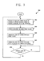
- Fig. 3 is a flow chart 200 for matching an antenna of a mobile communication terminal 100 in accordance with the preferred embodiment of the present invention as described in Fig. 2.
- the method sequentially measures power emission values of the antenna from antenna matching units connected between the antenna and the internal circuit unit (S31).
- the sequentially measured power emission values are stored in memory (S33).
- the stored power emission values are compared to each other (S35).
- Antenna matching units are selectively connected between the antenna and an internal circuit unit based on a result of the comparison (S37).
- the method checks whether a selected time has elapsed since the antenna matching units are connected (S39).
- the controller 152 sequentially connects selected antenna matching units 130A, 130B, and 130C to the antenna 110 and to the internal circuit unit 150.
- the antenna coupler 160 sequentially measures the power emission values of the antenna 110 connected to the antenna matching units 130 (S31).
- the antenna coupler 160 outputs the measured power emission values to memory 151 (S33).
- the selected number of the antenna matching units is set to two or greater.
- the selected antenna matching units are preferably implemented in consideration of various situations at the initial stage of designing a mobile communication terminal.
- the selected antenna matching units are chosen for setting the voltage standing wave ratio (VSWR) values of the antenna within an ideal range under selected circumstances.
- VSWR voltage standing wave ratio
- the controller 152 sets index values of the selected antenna matching units 130A, 130B, and 130C.
- the controller 152 stores set index values of the antenna matching units 130A, 130B, and 130C and power emission values corresponding to the antenna matching units 130A, 130B, and 130C having the index values in the memory 151 (S33).
- the controller 152 compares the stored power emission values (S35), and outputs a control signal to a first and a second path controller 120 and 140.
- the control signal provides information for selection of an antenna matching unit, such as 130A, 130B, and/or 130C, in this exemplary example, to provide an optimal power emission value for the antenna 110 of the mobile terminal.
- the optimal power emission value may be the greatest power emission value or a user defined power emission value based on a selected criteria.
- a first and second path controllers 120 and 140 connect selectively at least one of the antenna matching units for producing the optimal emission power value between the antenna and the internal circuit unit associated with the control signal (S37).
- the first path controller 120 connects the selected antenna matching unit to the antenna 110.
- the second path controller 140 connects the selected antenna matching unit to the internal circuit unit 150.
- the controller 152 checks whether a selected time has elapsed based on when the selected antenna matching unit, such as 130A, 130B, and 130C, was selected and connected to the antenna (S39). When the selected time has elapsed, the controller 152 repeatedly sequentially measures power emission values of the antenna 110 to which the selected antenna matching units have been connected. If the selected time has not elapsed, the controller 152 continuously connects the selected antenna matching units.
- the selected time is preferably set to approximately one minute.
- the present invention provides an apparatus for measuring power emission values of the antenna for selecting and connecting at least one of the antenna matching units 130A, 130B, and 130C.
- the emission power measurement occurs within a selected time of at least one of the antenna matching units 130A, 130B, and 130C selectively connected to the antenna 110 and an internal circuit unit 150.
- the emission power performance of the antenna 110 can be optimized based on the circumstances or the changes in circumstances of the mobile communication terminal.
- the present invention is described in the context of a mobile terminal, the present invention may also be used in any wired or wireless communication systems using mobile devices, such as PDAs and laptop computers equipped with wired and wireless communication capabilities. Moreover, the use of certain terms to describe the present invention should not limit the scope of the present invention to certain type of wireless communication system, such as UMTS. The present invention is also applicable to other wireless communication systems using different air interfaces and/or physical layers, for example, TDMA, CDMA, FDMA, WCDMA, etc.
- Code in the computer readable medium is accessed and executed by a processor.
- the code in which preferred embodiments are implemented may further be accessible through a transmission media or from a file server over a network.
- the article of manufacture in which the code is implemented may comprise a transmission media, such as a network transmission line, wireless transmission media, signals propagating through space, radio waves, infrared signals, etc.
- a transmission media such as a network transmission line, wireless transmission media, signals propagating through space, radio waves, infrared signals, etc.
Landscapes
- Engineering & Computer Science (AREA)
- Computer Networks & Wireless Communication (AREA)
- Signal Processing (AREA)
- Mobile Radio Communication Systems (AREA)
- Transmitters (AREA)
- Telephone Function (AREA)
- Transceivers (AREA)
Abstract
Description
- The present invention relates to a mobile communication terminal, and more particularly, to an apparatus and method for matching an antenna to optimize emission performance of the mobile communication terminal.
- A mobile communication terminal communicates a signal from one user utilizing a wireless page, transmitted through a mobile switching center (MSC), to another user. A base station (BS) monitors a user's movement through a mobile service area. A conventional mobile communication terminal includes an antenna for transmitting and/or receiving signals.
- Research is ongoing to improve sensitivity of an antenna within a noisy environment. The noisy environment may be result from noise generated from electronic devices and other obstacles, such as buildings, within a communication path. A matching network for an antenna is a crucial component for providing a high quality signal for reception by a user.
- A conventional apparatus for matching an antenna of a mobile communication terminal is disclosed in Fig. 1. The
conventional apparatus 1 for matching an antenna of a mobile communication terminal comprises anantenna 10 for transmitting and/or receiving a signal, an antenna matchingunit 30 connected to theantenna 10, and acircuit unit 50 connected to theantenna matching unit 30. - The antenna matching
unit 30 matches theantenna 10 for a single condition. The antenna matchingunit 30, in one example, is implemented for the single condition that users are not holding the mobile terminal. In another example, the antenna matchingunit 30 is implemented for the single condition that users position the mobile terminal using one hand proximal to an ear. If the antenna matchingunit 30 is implemented for situations other than the single condition, a large voltage standing wave ratio (VSWR) will appear at theantenna 10. The large voltage standing wave ratio results in received signals having a weak electric field strength. The mobile terminal is required to increase power consumption of a battery supply to compensate for the weak electric field strength. The increased power consumption results in decreased talk time for the mobile terminal. - Therefore, there is a need for a system that overcomes the above problems and provides advantages over other signal matching systems.
- Features and advantages of the invention will be set forth in the description which follows, and in part will be apparent from the description, or may be learned by practice of the invention. The objectives and other advantages of the invention will be realized and attained by the structure particularly pointed out in the written description and claims hereof as well as the appended drawings.
- In one embodiment, an apparatus comprises antenna matching units for connecting to the antenna, and a path controller connecting at least one of the antenna matching units between the antenna and an internal circuit unit for measuring power emission values of the antenna with the at least one of the antenna matching units. The path controller selects, in one example, from the at least one of the antenna matching units for connecting to the antenna based on an optimal power emission value of the measured power emission values for matching the antenna.
- In another embodiment, a method comprises measuring power emission values of the antenna to which at least one of antenna matching units has been connected, storing the measured power emission values, comparing the stored measured power emission values relative to each other for determining at least one optimal antenna matching unit based on an optimal power emission value of the measured power emission values, and connecting the at least one optimal antenna matching unit between the antenna and an internal circuit unit. The optimal power emission value preferably is the greatest power emission value of the antenna. In the alternative, the optimal power emission value may be a user defined criteria.
- Additional features and advantages of the invention will be set forth in the description which follows, and in part will be apparent from the description, or may be learned by practice of the invention. It is to be understood that both the foregoing general description and the following detailed description of the present invention are exemplary and explanatory and are intended to provide further explanation of the invention as claimed.
- These and other embodiments will also become readily apparent to those skilled in the art from the following detailed description of the embodiments having reference to the attached figures, the invention not being limited to any particular embodiments disclosed.
- The accompanying drawings, which are included to provide a further understanding of the invention and are incorporated in and constitute a part of this specification, illustrate embodiments of the invention and together with the description serve to explain the principles of the invention.
- Features, elements, and aspects of the invention that are referenced by the same numerals in different figures represent the same, equivalent, or similar features, elements, or aspects in accordance with one or more embodiments.
- The invention will be described in detail with reference to the following drawings in which like reference numerals refer to like elements wherein:
- Fig. 1 is a block diagram showing a conventional apparatus for matching an antenna of a mobile communication terminal.
- Fig. 2 is a block diagram showing an apparatus for matching an antenna of a mobile communication terminal in accordance with a preferred embodiment of the present invention.
- Fig. 3 is a flow chart of a method for matching an antenna of a mobile communication terminal in accordance with the preferred embodiment of the present invention.
- The invention relates to an apparatus and method for matching an antenna of the mobile communication terminal for optimizing emission performance of the antenna.
- Although the invention is illustrated with respect to a mobile terminal, it is contemplated that the invention may be utilized anywhere it is desired for efficiently transmit and receive signals. Reference will now be made in detail to the preferred embodiments of the present invention, examples of which are illustrated in the accompanying drawings. Preferred embodiments of the present invention will now be described with reference to the accompanying drawings.
- The invention provides an apparatus for selection of antenna matching units wherein at least one antenna matching unit is selectively connected to an antenna and the internal circuit unit of the mobile communication terminal. The invention further provides for the antenna being optimally matched according to a selected condition of the mobile communication terminal for optimizing the emission performance of the antenna.
- Fig. 2 is a block diagram showing an
apparatus 100 for matching an antenna of a mobile communication terminal in accordance with a preferred embodiment of the present invention. Anantenna 110 transmits and/or receives a signal. First andsecond path controllers units antenna 110 and to aninternal circuit unit 150. Anantenna coupler 160 measures power emission values of theantenna 110 utilizing, for example, the selected antenna such asmatching units antenna coupler 160 outputs measured power emission values to aninternal circuit unit 150. Theinternal circuit unit 150 has amemory 151 and acontroller 152. Thememory 151 stores the outputted power emission values. Thecontroller 152 outputs a control signal to the first andsecond path controllers units antenna 110 emission performance. The selected antenna matching units are connected in theapparatus 100. - Fig. 3 is a
flow chart 200 for matching an antenna of amobile communication terminal 100 in accordance with the preferred embodiment of the present invention as described in Fig. 2. The method sequentially measures power emission values of the antenna from antenna matching units connected between the antenna and the internal circuit unit (S31). The sequentially measured power emission values are stored in memory (S33). The stored power emission values are compared to each other (S35). Antenna matching units are selectively connected between the antenna and an internal circuit unit based on a result of the comparison (S37). The method checks whether a selected time has elapsed since the antenna matching units are connected (S39). - The following is one exemplary example of the flow chart for Fig. 3. In this exemplary example, the
controller 152 sequentially connects selected antenna matchingunits antenna 110 and to theinternal circuit unit 150. The antenna coupler 160 sequentially measures the power emission values of theantenna 110 connected to the antenna matching units 130 (S31). Theantenna coupler 160 outputs the measured power emission values to memory 151 (S33). - Preferably, the selected number of the antenna matching units is set to two or greater. The selected antenna matching units are preferably implemented in consideration of various situations at the initial stage of designing a mobile communication terminal. The selected antenna matching units are chosen for setting the voltage standing wave ratio (VSWR) values of the antenna within an ideal range under selected circumstances.
- The
controller 152 sets index values of the selectedantenna matching units controller 152 stores set index values of theantenna matching units antenna matching units - The
controller 152 compares the stored power emission values (S35), and outputs a control signal to a first and asecond path controller antenna 110 of the mobile terminal. The optimal power emission value may be the greatest power emission value or a user defined power emission value based on a selected criteria. - A first and
second path controllers first path controller 120 connects the selected antenna matching unit to theantenna 110. Thesecond path controller 140 connects the selected antenna matching unit to theinternal circuit unit 150. - The
controller 152 checks whether a selected time has elapsed based on when the selected antenna matching unit, such as 130A, 130B, and 130C, was selected and connected to the antenna (S39). When the selected time has elapsed, thecontroller 152 repeatedly sequentially measures power emission values of theantenna 110 to which the selected antenna matching units have been connected. If the selected time has not elapsed, thecontroller 152 continuously connects the selected antenna matching units. The selected time is preferably set to approximately one minute. - The present invention provides an apparatus for measuring power emission values of the antenna for selecting and connecting at least one of the
antenna matching units antenna matching units antenna 110 and aninternal circuit unit 150. The emission power performance of theantenna 110 can be optimized based on the circumstances or the changes in circumstances of the mobile communication terminal. - Although the present invention is described in the context of a mobile terminal, the present invention may also be used in any wired or wireless communication systems using mobile devices, such as PDAs and laptop computers equipped with wired and wireless communication capabilities. Moreover, the use of certain terms to describe the present invention should not limit the scope of the present invention to certain type of wireless communication system, such as UMTS. The present invention is also applicable to other wireless communication systems using different air interfaces and/or physical layers, for example, TDMA, CDMA, FDMA, WCDMA, etc.
- Code in the computer readable medium is accessed and executed by a processor. The code in which preferred embodiments are implemented may further be accessible through a transmission media or from a file server over a network. In such cases, the article of manufacture in which the code is implemented may comprise a transmission media, such as a network transmission line, wireless transmission media, signals propagating through space, radio waves, infrared signals, etc. Of course, those skilled in the art will recognize that many modifications may be made to this configuration without departing from the scope of the present invention, and that the article of manufacture may comprise any information bearing medium known in the art.
- The logic implementation shown in the figures described specific operations as occurring in a particular order. In alternative implementations, certain of the logic operations may be performed in a different order, modified or removed and still implement preferred embodiments of the present invention. Moreover, steps may be added to the above described logic and still conform to implementations of the invention.
- The foregoing embodiments and advantages are merely exemplary and are not to be construed as limiting the present invention. The present teaching can be readily applied to other types of systems. The description of the present invention is intended to be illustrative, and not to limit the scope of the claims. Many alternatives, modifications, and variations will be apparent to those skilled in the art. Accordingly, the invention is not limited to the precise embodiments described in detail hereinabove.
Claims (24)
- An apparatus for matching an antenna of a mobile communication terminal, the apparatus comprising:antenna matching units for connecting to the antenna; anda path controller connecting at least one of the antenna matching units between the antenna and an internal circuit unit for measuring power emission values of the antenna with the at least one of the antenna matching units,wherein the path controller selects from the at least one of the antenna matching units for connecting to the antenna based on an optimal power emission value of the measured power emission values for matching the antenna.
- The apparatus of claim 1, further comprising:an antenna coupler for measuring the power emission values of the antenna utilizing the at least one of the antenna matching units.
- The apparatus of claim 2, wherein the internal circuit unit comprises:a controller for outputting a control signal to selectively connect at least one of the antenna matching units associated with the measured power emission values to the antenna.
- The apparatus of claim 3, wherein the internal circuit unit further comprises:memory for storing the measured power emission values.
- The apparatus of claim 4, wherein the internal circuit unit further comprises:index values corresponding to the antenna and the at least one of the antenna matching units are set which are associated with the measured power emission values.
- The apparatus of claim 5, wherein the path controller sets the index values of the at least one of the antenna matching units corresponding to the measured power emission values.
- The apparatus of claim 1, wherein the path controller comprises a first path controller for selectively connecting the antenna and the at least one of the antenna matching units.
- The apparatus of claim 1, wherein the path controller includes a second path controller for selectively connecting the at least one of the antenna matching units and the internal circuit unit.
- A method for decreasing a voltage standing wave ratio of a match network between an antenna of a mobile communication terminal and a communication signal, the method comprising:measuring power emission values of the antenna to which at least one of antenna matching units has been connected;storing the measured power emission values;comparing the stored measured power emission values relative to each other for determining at least one optimal antenna matching unit based on an optimal power emission value of the measured power emission values; andconnecting the at least one optimal antenna matching unit between the antenna and an internal circuit unit.
- The method of claim 9, wherein the optimal power emission value is the greatest power emission value of the antenna.
- The method of claim 9, further comprising:setting index values of the antenna matching units corresponding to the measured power emission power values of the antenna matching units.
- The method of claim 9, wherein storing the measured power emission values of the antenna further comprises:associating the measured power emission power values with corresponding index values of the antenna matching units.
- The method of claim 9, wherein connecting at least one of the antenna matching units further comprises determining an antenna matching unit having an optimal power emission value.
- The method of claim 9, further comprising:determining if a selected time has elapsed when the at least one of the antenna matching units is connected to the antenna.
- The method of claim 9, further comprising:determining repeatedly if a selected time has elapsed for at least one of the antenna matching units being connected to the antenna.
- The method of claim 14, wherein the selected time is approximately one minute.
- The method of claim 14, further comprising:determining if the selected time has not elapsed and continuously connecting at least one of the antenna matching units to the antenna while the selected time has not elapsed.
- An apparatus for matching an antenna of a mobile communication terminal, the apparatus comprising:antenna matching units for connecting to the antenna;a path controller for connecting at least one of the antenna matching units to the antenna and to an internal circuit unit; andan antenna coupler for measurement of power emission values of the antenna utilizing the antenna matching units,wherein the internal circuit unit comprises a controller for outputting a control signal for connecting the antenna matching units associated with the measured power emission values, andwherein the path controller connects the at least one of the antenna matching units and the antenna associated with an optimal power emission value for matching the antenna.
- The apparatus of claim 18, wherein the internal circuit unit further comprises:memory for storing the measured power emission values.
- The apparatus of claim 18, wherein the optimal power emission value is a greatest power emission value for the antenna.
- The apparatus of claim 18, where the internal circuit further comprises:index values corresponding to the antenna and the at least one of the antenna matching units being set based on the measured power emission values.
- The apparatus of claim 18, wherein the path controller comprises a first path controller for connecting at least one of the antenna matching unit to the antenna.
- The apparatus of claim 18, wherein the path controller sets index values of the at least one of the antenna matching units corresponding to the measured power emission values.
- The apparatus of claim 22, wherein the path controller comprises a second path controller for connecting at least one of the antenna matching units and the internal circuit unit.
Applications Claiming Priority (1)
| Application Number | Priority Date | Filing Date | Title |
|---|---|---|---|
| KR1020040085930A KR100677370B1 (en) | 2004-10-26 | 2004-10-26 | Apparatus and method for matching antenna of mobile communication terminal |
Publications (1)
| Publication Number | Publication Date |
|---|---|
| EP1653611A1 true EP1653611A1 (en) | 2006-05-03 |
Family
ID=34934785
Family Applications (1)
| Application Number | Title | Priority Date | Filing Date |
|---|---|---|---|
| EP20050007471 Ceased EP1653611A1 (en) | 2004-10-26 | 2005-04-05 | Apparatus and method for matching an antenna of a mobile communication terminal |
Country Status (5)
| Country | Link |
|---|---|
| US (1) | US20060094486A1 (en) |
| EP (1) | EP1653611A1 (en) |
| JP (1) | JP4112566B2 (en) |
| KR (1) | KR100677370B1 (en) |
| CN (1) | CN1767399A (en) |
Cited By (1)
| Publication number | Priority date | Publication date | Assignee | Title |
|---|---|---|---|---|
| WO2009033510A1 (en) * | 2007-09-13 | 2009-03-19 | Sony Ericsson Mobile Communications Ab | Adaptive antenna matching |
Families Citing this family (8)
| Publication number | Priority date | Publication date | Assignee | Title |
|---|---|---|---|---|
| FI20065339A0 (en) * | 2006-05-18 | 2006-05-18 | Nokia Corp | Antenna matching measurement and gain control |
| JP2009253479A (en) * | 2008-04-02 | 2009-10-29 | Sony Ericsson Mobilecommunications Japan Inc | Mobile communication terminal and method of controlling transmission characteristics thereof |
| US20120108195A1 (en) * | 2009-07-02 | 2012-05-03 | Samsung Electronics Co., Ltd. | Method for matching an antenna of a portable terminal and apparatus for same |
| WO2011024506A1 (en) * | 2009-08-25 | 2011-03-03 | 株式会社村田製作所 | Antenna device |
| US20120071108A1 (en) * | 2010-09-20 | 2012-03-22 | Mediatek Inc. | Radio Frequency Signal Control Module and Radio Frequency Signal Controlling Method |
| US8874041B2 (en) | 2011-10-03 | 2014-10-28 | Apple Inc. | Electronic device with service acquisition antenna switching |
| CN105990683B (en) * | 2015-02-04 | 2020-10-09 | 深圳富泰宏精密工业有限公司 | Device and method for adjusting antenna |
| CN107437968B (en) * | 2016-05-26 | 2021-03-23 | 中兴通讯股份有限公司 | Radio frequency transmitting circuit and circuit matching method |
Citations (7)
| Publication number | Priority date | Publication date | Assignee | Title |
|---|---|---|---|---|
| GB2289989A (en) * | 1994-05-25 | 1995-12-06 | Nokia Mobile Phones Ltd | Antenna impedance matching arrangement |
| GB2330965A (en) * | 1997-10-28 | 1999-05-05 | Nec Corp | A mobile radio communication device with an adjustment of the impedance matching, as affected by human presence, of the aerial to the device |
| JPH11251956A (en) * | 1998-03-05 | 1999-09-17 | Nec Corp | Antenna matching adjustment circuit |
| GB2355341A (en) * | 1999-09-07 | 2001-04-18 | Nec Corp | Portable telephone which compensates for change of antenna impedance |
| GB2365628A (en) * | 2000-03-22 | 2002-02-20 | Matsushita Electric Ind Co Ltd | Antenna and impedance matching apparatus |
| JP2003243998A (en) | 2002-02-21 | 2003-08-29 | Hitachi Kokusai Electric Inc | Radio equipment |
| EP1398875A1 (en) | 2002-09-12 | 2004-03-17 | Filtronic LK Oy | System for controlling the transmitting power of a multiband antenna |
Family Cites Families (9)
| Publication number | Priority date | Publication date | Assignee | Title |
|---|---|---|---|---|
| JPH0766614A (en) * | 1993-08-24 | 1995-03-10 | Oki Electric Ind Co Ltd | Retractable antenna |
| US5564086A (en) * | 1993-11-29 | 1996-10-08 | Motorola, Inc. | Method and apparatus for enhancing an operating characteristic of a radio transmitter |
| JP2692670B2 (en) * | 1995-12-28 | 1997-12-17 | 日本電気株式会社 | Antenna for portable radio |
| JPH11136157A (en) * | 1997-10-28 | 1999-05-21 | Nec Corp | Mobile radio terminal equipment |
| JP3131967B2 (en) * | 1997-11-05 | 2001-02-05 | 日本電気株式会社 | Antenna circuit |
| EP1137192B1 (en) * | 2000-03-18 | 2005-11-23 | Siemens Aktiengesellschaft | Radio station for transmitting signals |
| KR20020051044A (en) * | 2000-12-22 | 2002-06-28 | 송문섭 | Antenna matching device in mobile station system |
| KR20040070618A (en) * | 2003-02-04 | 2004-08-11 | 엘지전자 주식회사 | Multi-matching apparatus and method for antenna |
| KR20050020129A (en) * | 2003-08-21 | 2005-03-04 | 주식회사 팬택앤큐리텔 | Device for matching variable antenna |
-
2004
- 2004-10-26 KR KR1020040085930A patent/KR100677370B1/en not_active IP Right Cessation
-
2005
- 2005-04-05 EP EP20050007471 patent/EP1653611A1/en not_active Ceased
- 2005-04-15 JP JP2005118996A patent/JP4112566B2/en not_active Expired - Fee Related
- 2005-05-18 CN CNA2005100746501A patent/CN1767399A/en active Pending
- 2005-07-12 US US11/180,465 patent/US20060094486A1/en not_active Abandoned
Patent Citations (7)
| Publication number | Priority date | Publication date | Assignee | Title |
|---|---|---|---|---|
| GB2289989A (en) * | 1994-05-25 | 1995-12-06 | Nokia Mobile Phones Ltd | Antenna impedance matching arrangement |
| GB2330965A (en) * | 1997-10-28 | 1999-05-05 | Nec Corp | A mobile radio communication device with an adjustment of the impedance matching, as affected by human presence, of the aerial to the device |
| JPH11251956A (en) * | 1998-03-05 | 1999-09-17 | Nec Corp | Antenna matching adjustment circuit |
| GB2355341A (en) * | 1999-09-07 | 2001-04-18 | Nec Corp | Portable telephone which compensates for change of antenna impedance |
| GB2365628A (en) * | 2000-03-22 | 2002-02-20 | Matsushita Electric Ind Co Ltd | Antenna and impedance matching apparatus |
| JP2003243998A (en) | 2002-02-21 | 2003-08-29 | Hitachi Kokusai Electric Inc | Radio equipment |
| EP1398875A1 (en) | 2002-09-12 | 2004-03-17 | Filtronic LK Oy | System for controlling the transmitting power of a multiband antenna |
Non-Patent Citations (1)
| Title |
|---|
| PATENT ABSTRACTS OF JAPAN vol. 1999, no. 14 22 December 1999 (1999-12-22) * |
Cited By (2)
| Publication number | Priority date | Publication date | Assignee | Title |
|---|---|---|---|---|
| WO2009033510A1 (en) * | 2007-09-13 | 2009-03-19 | Sony Ericsson Mobile Communications Ab | Adaptive antenna matching |
| US7746290B2 (en) | 2007-09-13 | 2010-06-29 | Sony Ericsson Mobile Communications Ab | Adaptive antenna matching |
Also Published As
| Publication number | Publication date |
|---|---|
| JP2006129428A (en) | 2006-05-18 |
| CN1767399A (en) | 2006-05-03 |
| KR100677370B1 (en) | 2007-02-02 |
| JP4112566B2 (en) | 2008-07-02 |
| US20060094486A1 (en) | 2006-05-04 |
| KR20060036817A (en) | 2006-05-02 |
Similar Documents
| Publication | Publication Date | Title |
|---|---|---|
| EP1653611A1 (en) | Apparatus and method for matching an antenna of a mobile communication terminal | |
| US7702335B2 (en) | Method of system access to a wireless network | |
| US8265554B2 (en) | Communication device and method using human body | |
| US8055197B2 (en) | Apparatus and method for bluetooth connection in portable terminal | |
| US7454227B2 (en) | Wireless communication module, communication terminal, and impedance matching method | |
| CN109150327B (en) | Antenna detection method, antenna detection device and mobile terminal | |
| TW201336167A (en) | Adaptive tunable antennas for wireless devices | |
| US8145204B2 (en) | Communication terminal out of range determination method, wireless communication system switching method and communication terminal | |
| US20070236296A1 (en) | Apparatus and method for preventing degradation of RF performance due to impedance change of antenna in mobile communication terminal | |
| US11411611B2 (en) | Communication device and method for operating the same | |
| CN108963451B (en) | Electronic device specific absorption rate adjusting method and device, electronic device and storage medium | |
| CN113783634A (en) | Method and apparatus for adjusting specific absorption rate of electromagnetic wave, medium, and electronic device | |
| CN108768548B (en) | Radio frequency calibration method, device, mobile terminal and computer readable storage medium | |
| CN108770055A (en) | Transmission power adjustment method, device and electronic device | |
| CN108832944B (en) | Power compensation method, device, terminal equipment and storage medium | |
| CN106550484B (en) | Direct call communication method and terminal | |
| JPH11136157A (en) | Mobile radio terminal equipment | |
| WO2014070559A1 (en) | Sub-channel detection for wireless data communication | |
| US8477632B2 (en) | Antenna testing device | |
| US10623973B2 (en) | Detection device and detection method | |
| US20050102541A1 (en) | System controller for controlling an output state | |
| CN114221678B (en) | Near field communication chip, wireless communication device, and specific absorption rate detection method | |
| CN117792427A (en) | Electronic equipment, control circuit of radio frequency antenna and power consumption control method of control circuit | |
| CN113725590A (en) | Antenna structure and terminal equipment | |
| CN117595893A (en) | Mobile communication system and method for determining use situation thereof |
Legal Events
| Date | Code | Title | Description |
|---|---|---|---|
| PUAI | Public reference made under article 153(3) epc to a published international application that has entered the european phase |
Free format text: ORIGINAL CODE: 0009012 |
|
| 17P | Request for examination filed |
Effective date: 20050405 |
|
| AK | Designated contracting states |
Kind code of ref document: A1 Designated state(s): AT BE BG CH CY CZ DE DK EE ES FI FR GB GR HU IE IS IT LI LT LU MC NL PL PT RO SE SI SK TR |
|
| AX | Request for extension of the european patent |
Extension state: AL BA HR LV MK YU |
|
| 17Q | First examination report despatched |
Effective date: 20060929 |
|
| AKX | Designation fees paid |
Designated state(s): AT BE BG CH CY CZ DE DK EE ES FI FR GB GR HU IE IS IT LI LT LU MC NL PL PT RO SE SI SK TR |
|
| RAP1 | Party data changed (applicant data changed or rights of an application transferred) |
Owner name: LG ELECTRONICS INC. |
|
| STAA | Information on the status of an ep patent application or granted ep patent |
Free format text: STATUS: THE APPLICATION HAS BEEN REFUSED |
|
| 18R | Application refused |
Effective date: 20150423 |