EP1652328B1 - Use of polarization for differentiation of information - Google Patents
Use of polarization for differentiation of information Download PDFInfo
- Publication number
- EP1652328B1 EP1652328B1 EP04748771A EP04748771A EP1652328B1 EP 1652328 B1 EP1652328 B1 EP 1652328B1 EP 04748771 A EP04748771 A EP 04748771A EP 04748771 A EP04748771 A EP 04748771A EP 1652328 B1 EP1652328 B1 EP 1652328B1
- Authority
- EP
- European Patent Office
- Prior art keywords
- packets
- optical
- packet
- polarization
- qos
- Prior art date
- Legal status (The legal status is an assumption and is not a legal conclusion. Google has not performed a legal analysis and makes no representation as to the accuracy of the status listed.)
- Not-in-force
Links
- 230000010287 polarization Effects 0.000 title claims abstract description 49
- 230000004069 differentiation Effects 0.000 title description 4
- 230000003287 optical effect Effects 0.000 claims abstract description 102
- 238000000034 method Methods 0.000 claims abstract description 32
- 230000011664 signaling Effects 0.000 claims abstract description 6
- 238000004891 communication Methods 0.000 claims description 24
- 239000011159 matrix material Substances 0.000 claims description 9
- 238000000926 separation method Methods 0.000 abstract description 18
- 230000005540 biological transmission Effects 0.000 abstract description 17
- 239000000835 fiber Substances 0.000 description 18
- 239000000872 buffer Substances 0.000 description 17
- 238000013461 design Methods 0.000 description 17
- 230000015556 catabolic process Effects 0.000 description 12
- 238000006731 degradation reaction Methods 0.000 description 12
- 238000013459 approach Methods 0.000 description 7
- 230000003139 buffering effect Effects 0.000 description 4
- 238000012545 processing Methods 0.000 description 4
- 230000008859 change Effects 0.000 description 3
- 230000006866 deterioration Effects 0.000 description 3
- 238000013508 migration Methods 0.000 description 3
- 230000005012 migration Effects 0.000 description 3
- 230000009467 reduction Effects 0.000 description 3
- 238000005204 segregation Methods 0.000 description 3
- 238000004088 simulation Methods 0.000 description 3
- 238000010561 standard procedure Methods 0.000 description 3
- 230000003068 static effect Effects 0.000 description 3
- 238000012546 transfer Methods 0.000 description 3
- 101150071746 Pbsn gene Proteins 0.000 description 2
- 241000162337 Stolas Species 0.000 description 2
- 238000006880 cross-coupling reaction Methods 0.000 description 2
- 230000003247 decreasing effect Effects 0.000 description 2
- 230000003111 delayed effect Effects 0.000 description 2
- 239000006185 dispersion Substances 0.000 description 2
- 238000005516 engineering process Methods 0.000 description 2
- 230000010354 integration Effects 0.000 description 2
- 238000013507 mapping Methods 0.000 description 2
- 238000005259 measurement Methods 0.000 description 2
- 239000013307 optical fiber Substances 0.000 description 2
- 239000004065 semiconductor Substances 0.000 description 2
- 241000736774 Uria aalge Species 0.000 description 1
- 230000002776 aggregation Effects 0.000 description 1
- 238000004220 aggregation Methods 0.000 description 1
- 230000003321 amplification Effects 0.000 description 1
- 238000004458 analytical method Methods 0.000 description 1
- 230000008901 benefit Effects 0.000 description 1
- 238000010276 construction Methods 0.000 description 1
- 230000008878 coupling Effects 0.000 description 1
- 238000010168 coupling process Methods 0.000 description 1
- 238000005859 coupling reaction Methods 0.000 description 1
- 238000001514 detection method Methods 0.000 description 1
- 238000011161 development Methods 0.000 description 1
- 230000000694 effects Effects 0.000 description 1
- 230000007613 environmental effect Effects 0.000 description 1
- 238000002675 image-guided surgery Methods 0.000 description 1
- 238000002372 labelling Methods 0.000 description 1
- 239000012464 large buffer Substances 0.000 description 1
- 238000012423 maintenance Methods 0.000 description 1
- 238000003199 nucleic acid amplification method Methods 0.000 description 1
- 230000001902 propagating effect Effects 0.000 description 1
- 238000011160 research Methods 0.000 description 1
- 230000035945 sensitivity Effects 0.000 description 1
- 230000003595 spectral effect Effects 0.000 description 1
- 238000001228 spectrum Methods 0.000 description 1
- 238000001356 surgical procedure Methods 0.000 description 1
- 238000012360 testing method Methods 0.000 description 1
- 230000009466 transformation Effects 0.000 description 1
- 238000000844 transformation Methods 0.000 description 1
Images


Classifications
-
- H—ELECTRICITY
- H04—ELECTRIC COMMUNICATION TECHNIQUE
- H04J—MULTIPLEX COMMUNICATION
- H04J14/00—Optical multiplex systems
- H04J14/06—Polarisation multiplex systems
-
- H—ELECTRICITY
- H04—ELECTRIC COMMUNICATION TECHNIQUE
- H04J—MULTIPLEX COMMUNICATION
- H04J14/00—Optical multiplex systems
- H04J14/02—Wavelength-division multiplex systems
-
- H—ELECTRICITY
- H04—ELECTRIC COMMUNICATION TECHNIQUE
- H04Q—SELECTING
- H04Q11/00—Selecting arrangements for multiplex systems
-
- H—ELECTRICITY
- H04—ELECTRIC COMMUNICATION TECHNIQUE
- H04Q—SELECTING
- H04Q11/00—Selecting arrangements for multiplex systems
- H04Q11/0001—Selecting arrangements for multiplex systems using optical switching
- H04Q11/0005—Switch and router aspects
- H04Q2011/0007—Construction
-
- H—ELECTRICITY
- H04—ELECTRIC COMMUNICATION TECHNIQUE
- H04Q—SELECTING
- H04Q11/00—Selecting arrangements for multiplex systems
- H04Q11/0001—Selecting arrangements for multiplex systems using optical switching
- H04Q11/0005—Switch and router aspects
- H04Q2011/0007—Construction
- H04Q2011/0035—Construction using miscellaneous components, e.g. circulator, polarisation, acousto/thermo optical
Definitions
- the present invention relates to polarisation to distinguish QoS classes, and to distinguish payload and header in packets within communicational networks. More generally the present invention relates to a new and improved use of states of polarisation within all types of communicational networks.
- optical network elements have a functionality which can operate effectively within a packet switched network.
- OPS optical packet switching
- optical burst switching where packets or bursts of packets are switched directly in the optical layer with optical switches.
- optical signal processing is still immature there are very restricted possibilities for signalling different types of information such as address information.
- Dimensions available for transfer of-information in an optical fibre are: intensity, time, frequency, phase and polarization. All these dimensions are through the years suggested used for different purposes.
- the formats of modulation used in optical links and networks are today based on NRZ- and RZ-formats where intensity varies between a minimum- and maximum level.
- the signals are time divisional multiplexed (TDM) with a data rate between 2,5 and 40 Gb/sec.
- TDM time divisional multiplexed
- WDM Wavelength Division Multiplexing
- the optical frequency is also suggested used as a label with optical networks where the framework from MPLS is used. Phase and frequency are suggested used as a form of modulation as to increase spectral efficiency likely in combination with polarization.
- serial header Several techniques have been proposed for in-band header encoding, like serial header, SubCarrier Modulation (SCM), and Frequency Shift Keying (FSK).
- SCM SubCarrier Modulation
- FSK Frequency Shift Keying
- serial header requires a fast optical gate e.g. a Semiconductor Optical Amplifier (SOA), while SCM and FSK need an optical wavelength converter. This increases component count of complex and yet technologically immature components.
- SOA Semiconductor Optical Amplifier
- FSK Frequency Shift Keying
- GS Guaranteed service
- S-WRON Static or Dynamic Wavelength Routed Optical Network
- D-WRONs increases throughput efficiency, compared to S-WRONs, by dynamically reconfiguring the wavelength paths to adapt to the traffic demands.
- control plane operates on an ms to s timescale, and cannot be optimized to the bursty traffic patterns of OPS, where packet durations are typically in the ⁇ s range. Therefore, not even D-WRONs can achieve the throughput efficiency and granularity of statistical multiplexing.
- the packet switch The packet switch
- a packet switch may be partial optical and partial electronic or fully optical.
- EP. 07944684 A1 it is described an optical packet switched network with one or several nodes and a transmitter sending polarized packet signals.
- the packet signals comprising a header- and a payload separated from each other by way of orthogonal polarizing.
- CA 2352113 an optical method of communication where it is utilized a high speed polarized bit stuffing method.
- the method describes a way of using polarized bit-stuffing for separation of data packet instead of multiplexing data streams from different modulators. This increases the speed for transferring of data within an optical network.
- US 20030048506 it is shown a method for solving packet congestion at a node output using polarization multiplexing. Two packets arriving at different inputs are supposed to be switched to the same output hence to avoid packet congestion the packets are sent in different orthogonal polarisation states thus enabling simultaneous sending of the packets.
- OPS Optical packet switching
- QoS Quality of Service
- a statistically multiplexed packet switched network OPS
- the GS enabled by optical circuit switched networks like S-WRON/D-WRON
- a node design that allows full sharing of link bandwidth is proposed, and that allows a migration from an S-WRON to the more efficient combined network, by adding OPS capability. The efficiency of the node is studied using a simulator.
- the technique proposed here overcomes the drawbacks as described above by using orthogonal States of Polarisation (SOP) for separating packets and sending control information.
- SOP orthogonal States of Polarisation
- PBS Polarisation Beam Splitter
- the present invention discloses a system and a method in accordance with the independent claims enclosed.
- figure 1 it is given an example on how the states of polarization may be used for optical separation between two different QoS-classes.
- the same principle may be utilized to separate optically between a header- and a payload.
- the method may, with the use of a polarization beam splitter, separate the information independent of the wavelength. If a WDM-signal with a number of wavelengths is sent towards the splitter, the splitter will function as a demultiplexer for header- and payload or QoS-classes for all the wavelengths.
- Figure 2 illustrates one embodiment of the present invention.
- Header and payload separation is implemented by sending the header in a SOP labelled '1', and the payload in SOP '2', orthogonal to '1'. Separation is done using a PBS, allowing full transparency with respect to bit rate and signal format for both header and payload.
- the GS packets may be forwarded solely on the basis of their wavelength information using a wavelength router.
- These packets can be separated from e.g. Best Effort (BE) packets by transmitting BE packets in SOP '2', while GS packets are transmitted in the SOP '1', like in figure 2.
- BE packets will then pass through a wavelength routed network allowing GS, while BE packets will be interleaved with the GS packets at the output of each node, increasing the utilisation of the links.
- the GS- packets are delayed equally to the longest BE-packet in every node so that by detecting a GS-packet on the input one can reserve the output and make sure that for the moment no BE-packet is transmitted. In this way packet contentions between BE- and GS-packets are avoided.
- GS packets will then be sent in SOP '1', without an orthogonal polarisation header, while BE packets will be sent in the SOP '2' with a simultaneously transmitted header in SOP '1'.
- SOP '1' When a signal is observed in SOP '1', with a signal simultaneously present in SOP '2', the signal in SOP '1' is recognised as the header of a BE packet. If there is no signal simultaneously present in SOP '2', the signal is recognised as a GS packet.
- detection of the simultaneous presence of signals in the two SOP's enables distinction of GS packets and BE headers.
- serial BE header distinction can be implemented sending the signals from the two SOP's into an optical AND gate.
- the GS packets ' in SOP '1' are forwarded through the AND gate if SOP '2' is tion of GS packets and BE headers.
- serial BE header distinction can be implemented sending the signals from the two SOP's into an optical AND gate.
- the GS packets in SOP '1' are forwarded through the AND gate if SOP '2' is high, while if SOP '2' is low, a BE header in SOP '1' is present, and blocked by the gate.
- BE and GS packets can be sent simultaneously in both SOPs. This has the potential of doubling the link's bandwidth utilisation.
- the transmission properties of the principle have much in common with polarisation multiplexing: Depending on the fibre's birefringence, PMD and the link distance, signals are depolarised. However, unlike conventional polarisation multiplexing, where a polarisation demultiplexing is done only at the receiver node, the present invention includes polarisation demultiplexing, polarisation, SOP re-alignment and polarisation multiplexing in all intermediate "core nodes". This increases tolerance to depolarisation and changes in SOPs, thereby allowing longer transmission distances.
- the quality of the signal path through a network model using one of the described embodiments is shown.
- the experimental set-up corresponding to a network consisting of an ingress node, a core node and an egress node, is shown in figure 3.
- Two optical transmitters on the same wavelength are modulated at 2.488 Gb/s using two separate and decorrelated bit generators with PRBS of length 2 11 -1.
- the signals are combined using a polarisation maintaining coupling (PM) coupler, and amplified using an EDFA. After the first 25 km SMF link, the signals arrive at the "Core Node".
- a manual Polarisation Controller (PC) ensures an ideal SOP to allow optimum splitting of the two signals in a PBS.
- the two arms are combined using a PM coupler, and sent to the receiver node, through the second 25 km SMF link.
- the two signals are again realigned and separated, before sent to the receiver.
- Power penalties are found comparing transmission path and back-to-back Bit Error Rate (BER) curves in different configurations.
- BER Bit Error Rate
- the proposed node design according to the present invention is shown in figure 5, where an OPS module is added to an S-WRON node.
- Packets are divided into two classes: "GS", that follows the pre-assigned S-WRON path, and a Best Effort class, "BE", without service guarantees, which is switched using the packet switch module.
- the two packet classes are segregated by setting 1x2 switches based on information in a header, or as shown in the figure 5 by using orthogonal States of Polarization (SOP). Then each of the polarization states is assigned to each of the service classes.
- SOP orthogonal States of Polarization
- GS packets destinations are decided by the configuration of the cross coupling matrix and the individual wavelengths of the packets, as shown in figure 5, GS headers are superfluous. Since service class segregation is achieved using SOP, contrary to principles as known from the prior art of optical QoS separation using reservation of wavelengths in an OCS network, the wavelength domain can be entirely devoted to wavelength routing purposes.
- the control electronics register that a packet is present at the input before the packet is delayed in a FDL corresponding to the duration of a maximum sized BE packet, D BEMAX .
- the output for which the packet is scheduled is then reserved. If a BE packet is currently propagating through the reserved output, it will not collide with the newly arrived GS packet, because of the delay in the FDL. Alternatively, the output can be reserved D BEMAX in advance of the GS packet arrival by sending a control packet. If SOP is used for segregating the packet classes, the control packet should be sent in the same SOP as the GS packet, enabling simultaneous transmission with potentially earlier transmitted BE packets.
- Packet delay and packet loss is found by simulation. Independent, asynchronous traffic generators, generating fixed length packets are used.
- the BE packets have a length of 500 B, while the GS packets length is varied, and set to either 500 B or 50 kB.
- An output is reserved D BEMAX before a GS packet that arrives at the input enters the output.
- the packets interarrival times are negative exponential distributed (Poisson), corresponding to a load of 0.8 of a maximum load on each wavelength.
- Packet arrivals both BE and GS, are uniformly distributed at the switch inputs.
- BE packet destinations are uniformly distributed, thereby also among the outputs.
- the GS packets are forwarded to a fixed destination and wavelength, uniformly distributed, hence avoiding congestion with other GS packets.
- BE packets can stay in the buffer for an arbitrary period of time. There is no limit on the size of the buffer; however the registered maximum filling of the buffer was 632 packets. The use of a very large buffer is therefore avoided. Buffered packets are normally scheduled as soon as a destined output becomes available, but reordering of packets may occur in rare cases.
- the node performance is analysed in a transport network for 32 and 128 wavelengths at a node-degree of 8, varying the number of buffer inputs.
- the maximum delay measured was 0.21 times the packet duration, in the case of 60 buffer inputs, 50 % GS traffic share, 50 kB GS packet length, also giving maximum buffer filling. This is normally much lower than the transmission delay and hence negligible.
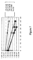
- the simulation results showing PLR, for GS packet share of 10% and 50 % of the total traffic load, measured in bytes, are shown in figure 6 and 7, respectively.
- the degradation is approximately one decade, and for 50 % GS traffic, the degradation is approximately three decades. Worth noticing is that when the number of buffer interfaces is further increased, causing lower PLR's, degradation is observed also when using GS packets of 50 kB length. At a pure BE system PLR of 10 -7 , the degradation is one half of a decade and one decade for 10% and 50% GS traffic shares, respectively.
- Figures 6 and 7 illustrates that the overhead caused by the reservation time is the main reason for the PLR degradation.
- a degradation increasing with the decreasing PLR and thus, number of interfaces can be observed.
- the GS packet length is large (50 kB)
- the degradation is low, independently of the GS traffic share.
- the degradation may be several decades. From the simulation results we conclude that the PLR penalty is low if the GS packets are much longer than D BEMAX . Since GS packets are given absolute priority, the very low BE PLR penalty observed, even when 50 % of the total traffic is GS packets, may come as a surprise.
- the number of BE packets are decreased, causing less problems with contention between BE packets and less load on the available buffer resources.
- An OPS node design supporting GS without packet loss and with fixed delay, as well as a BE service class is proposed.
- the design supports a migration strategy from circuit to packet switching by starting with an S-WRON module and adding an OPS module.
- High capacity utilisation is obtained by interleaving statistically multiplexed BE packets with GS packets that follow a pre-assigned wavelength path.
- the penalty of introducing GS packets in the system is shown to be very moderate if the GS packets is much longer than the BE packets. Aggregation of GS packets into bursts must therefore be considered.
- the switch has two switching matrixes, one electronic and one optical switch matrix.
- the electronic switching matrix is to a great extent similar to today's electronic switches switching matrix, as known from the Prior Art, and works together with the control entity in a manner known from Prior Art "Best Effort" switches.
- the optical switching matrix is supposed to function as a "wavelength router".
- An inward wavelength is sent to an appointed fibre and outward wavelength.
- the outward wavelength and the outward fibre are fixed according to the inward wavelength and the inward fibre.
- At the input the signal is split according to the optical signal's polarization.
- the advantage of this solution is a pure optical entity which may be used to split the traffic which is supposed to be handled as first priority, and which is supposed to be handled as BE-traffic.
- the solution presumes that the transmitting party is classifying priority traffic and BE traffic by sending these with orthogonal polarization relatively to each other.
- the solution may in principle be an addition to the electronic switch wherein the electronic switch is maintained as it is today, and handled "Best effort"-traffic, while the optical wavelength router is handling first priority traffic.
- the design will then differ from and be less optimal than shown in figure 8. There will be no possibilities for the electronic switch to let the optical switch handle the traffic when the latter has available capacity. The utilization of the optical part will therefore become less optimal; however the design becomes considerably simplified.
- figure 8 it is thought that a number of wavelengths reserves to the electronic switch and a number to the optical switch. If the optical switch is an addition, this number of wavelengths may be a fixed number, or it may be controlled centrally. If the two switches are built together from the beginning, the number of wavelengths can easier vary and be dynamic and be handled internally in the switch.
- BE packets may choose freely among all the wavelengths at the output of the switch. In the first stage be reserved so that the destined output is vacant when the packet occurs at the output of the optical buffer.
- BE packets may choose freely among all the wavelengths at the output of the switch.
- the output wavelengths is chosen.
- the QoS packets bypasses this first stage, hence the QoS packets input wavelength will decide the output wavelength at the output fibre.
- To which output fibre the packet is forwarded, is decided by the wavelength set by the packet switch's second row of wavelength-converters.
- the wavelength will be set to a fixed wavelength matching the input wavelength of specific input of a mux. Hence there is not possible changing the wavelength.
- node degree in a transport network will be in the order of say 4-8. Also the total number of nodes in the transport network will be limited.
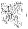
- COST 266 a reference scenario for a pan European network is given. Figure 11 illustrates this network. In the network a total of 37 Nodes is present, and it has a maximum node degree of 5. The question is whether a static configuration of QoS resources will be sufficiently effective in a transport network. Whether this is true will depend on the amount of QoS traffic in the network, and the number of wavelengths in each node. The packet switch design described will be effective only when a high number of wavelengths are available. This is because the design relies on using the wavelength dimension for contention resolution. Number of wavelengths should therefore be 32 or more
- wavelengths can dynamically be set up and taken down on demand. This will increase the utilization of the resources available for transmitting QoS packets, since it will allow dynamic changes in the traffic load.
- the node in figure 9. is slightly modified, replacing the fixed wavelength converters at the output with tuneable wavelength converters, the wavelength for a QoS path can be allowed to change along the way. This will allow a higher reuse factor of the wavelengths in the network.
- a technical problem when multiplexing the unpredictable wavelengths at the output of the tuneable wavelength converters has to be solved. Normally a low loss multiplexer will be wavelength sensitive. Other approaches to switching the wavelength in the node may be evaluated. when multiplexing the unpredictable wavelengths at the output of the tuneable wavelength converters has to be solved. Normally a low loss multiplexer will be wavelength sensitive. Other approaches to switching the wavelength in the node may be evaluated.
- the QoS packets do actually not need to be packets. They can be bursts of packets, i.e. burst switching can be performed, or it can be a semi-permanent line, i.e. line switching. It will all depend on the preferred approach.
- a QoS packet arrives at the input of the switch, a change in the state of polarisation will be detected. Hence it is known that it is a QoS packet.
- the state of polarisation has to be changed back to the "best effort state" so that when the QoS packet has passed the polarisation monitor, the switch will know the end of the packet. The output and the resources in the switch will then be freed, so that resources can be used by the Best Effort packets.
- the destination of the packet must be known in advance. This is for the switch to be able to set the wavelength converter in the second row of converters.
- the information about the QoS packet should be sent in advance. There are two approaches to this:
- the node design in figure 9 allows the QoS paths to be utilized by BE packets when QoS packets are not present.
- the lights state of polarisation is used for differencing between QoS and BE packets. Therefore, most of the capacity not used by the QoS traffic can be used by the BE packets by interleaving these packets in between the QoS packets or bursts.
- BE packets can be buffered and allocated a random wavelength along the path to its destination. This allows the capacity of the wavelengths, and also the wavelengths or paths reserved for transmission of QoS packets, to be efficiently utilized.
- a BE packet can, if it is available at one of the inputs or in the buffer, be switched to the reserved QoS path.
- the packet When a QoS packet occurs at the input of the switch (node), the packet will be sent in to an optical buffer with a delay corresponding to the length of the longest BE packet. While the QoS packet is in the buffer, the reserved QoS path at the output of the switch will be left vacant from the time when the last packet at this output has left the output until the QoS packet reaches the output of the buffer.
- the optical buffer will give a predictable delay, thus causing no jitter, with a magnitude insignificant compared to the transmission delay in the fibre between the nodes.
- Abbreviation list AWG Arrayed Waveguide Gratings a component using interferometer principles for wavelength routing or MUX/DEMUX.
- BE Best effort BER Bit Error Rate Cw Continuous Wave, laser emitting light, not modulated.
- D-WRON Dynamic Wavelength Routed Optical Network EDFA Erbium-Doped Fibre Amplifier A form of fibre optical amplification in which the transmitted light signal passes through a section erbium-doped fibre and is amplified by means of a laser pump diode. EDFA is used in transmitter booster amplifiers, in-line repeating amplifiers, and receiver preamplifiers. FDL Fibre Delay Line. FSK Frequency shift keying. A modulation technique for data transmission. It shifts the frequency above the carrier for a 1 and below the carrier for a 0 (zero) GMPLS Generalized Multiprotocol Label Switching GS Guaranteed service.
- MPLS Multiprotocol label switching this is a "multiprotocol forwarding standard" describing a method for integration of IP and ATM through label swapping.
- a IP- and ATM switch i.e. a MPLS switch, comprises ATM hardware with MPLS software.
- the software is IP addressing, IP-routing and label distribution protocol. NRZ Non Return to Zero.
- OCS Optical circuit switched (networks).
- OPS Optical packet switched (networks).
- OTDM Optical time division multiplexing.
- PC Polarisation Controller PLR Packet Loss Ratio PM Polarizing Maintaining.
- PMD Polarization Mode Dispersion this is a "multiprotocol forwarding standard" describing a method for integration of IP and ATM through label swapping.
- a test pattern having the properties of random data (generally 511 or 2047 bits), but generated in such manner that another circuit operating independently, can synchronize on the pattern and detect individual transmission bit errors.
- RZ Return to Zero.
- SCM Sub Carrier Modulation combines a signal with a single low frequency sine wave. The low frequency signal is called a subcarrier. This combined signal is then added to a higher frequency radio signal. The resulting high frequency radio signal is very complex and the original signal is not detectable by ordinary means.
- SMF Single mode Fibre.
- SOA Semiconductor Optical Amplifier.
Abstract
Description
- The present invention relates to polarisation to distinguish QoS classes, and to distinguish payload and header in packets within communicational networks. More generally the present invention relates to a new and improved use of states of polarisation within all types of communicational networks.
- With the introduction and the development of optical networks it is a goal to reduce the cost and complecity of data transmission within Tele and data networks. A major factor for achieving this is to reduce the number of signal transformations between optical and electrical signals. Such a reduction will reduce the number of components within the networks elements and reduce the need for electronic signal processing. Further a reduction in the number of components within the networks element will result in a reduction of the sources of errors, and hence reduced need for service and maintenance and an increased operational time. These factors will again result in a potentially reduced cost.
- The traffic volume of Internet is reported to show a significant increase despite the downturn of the telecommunication industry. Hence, increasing parts of the traffic in the transport network origins from packet data. For obvious economic reasons, new switching techniques should first be introduced at the time they show maturity and cost effectiveness. Hence there is a need to develop flexible optical networks supporting a seamless migration from an optical circuit switched (OCS) to an optical packet switched (OPS) backbone network.
- Thus by replacing electronical network element with optical network elements it is necessary that the optical network elements have a functionality which can operate effectively within a packet switched network. In the last few years intensive research have been spent on optical packet switching (OPS), and optical burst switching where packets or bursts of packets are switched directly in the optical layer with optical switches. These techniques are expected to be commercially of interest within approximately four years.
- As optical signal processing is still immature there are very restricted possibilities for signalling different types of information such as address information. Dimensions available for transfer of-information in an optical fibre are: intensity, time, frequency, phase and polarization. All these dimensions are through the years suggested used for different purposes.
- The formats of modulation used in optical links and networks are today based on NRZ- and RZ-formats where intensity varies between a minimum- and maximum level. The signals are time divisional multiplexed (TDM) with a data rate between 2,5 and 40 Gb/sec. In optical line switched networks the available and useable optical frequency spectrum is used for multiplexing a number of TDM-channels within one fibre, so called Wavelength Division Multiplexing (WDM). The optical frequency is also suggested used as a label with optical networks where the framework from MPLS is used. Phase and frequency are suggested used as a form of modulation as to increase spectral efficiency likely in combination with polarization.
- In connection with optical packet switching transfer of address information in the form of a header or a label is a problem for discussion. Normally, in an electronic router the header will be transferred at the beginning of the packet or the frame, and the address information and payload is thereby time multiplexed. Demultiplexing in the time domain is difficult using optical components. Transfer of address information separated from payload is therefore suggested carried out in different manners such as:
- 1a) Address and payload are separated by the use of separate optical wavelengths; this gives however a bad utilization of the wavelengths.
- 1b usage of a separate frequency within the optical wavelength, so-called Sub Carrier Modulation (SCM), utilizing the optical wavelength more efficiently than when a separate wavelength is used. However, this solution may lead to a deterioration of the payload signal.
- Ic) In the EU-sponsored project "STOLAS" it is suggested to use frequency modulation for modulation of packet header separated from the payload; however this method may also give a deterioration of the signal quality within the payload. STOLAS is an ongoing project within EUs 5th general plan "IST". Reference for this theme within the project: Sulur, T.K. et al. "IM/FSK Format for Payload/orthogonal Labelling IP Packets in IP over WDM Networks Supported by GMPLS-based LOBS." ONDM 2003, February 3-5, 2003, Budapest, Hungary.
- Several techniques have been proposed for in-band header encoding, like serial header, SubCarrier Modulation (SCM), and Frequency Shift Keying (FSK). However, they require advanced components for separation of header and payload, and reinsertion of new headers. To erase old header, before a new one can be inserted, per input wavelength, serial header requires a fast optical gate e.g. a Semiconductor Optical Amplifier (SOA), while SCM and FSK need an optical wavelength converter. This increases component count of complex and yet technologically immature components. Furthermore, if separation of packets belonging to different QoS classes is desirable, it will normally be done based on electronic processing of the header information, hence not all-optical.
-
- 1) Use of polarization of multiplexing/demultiplexing of two data channels (multiplexing by polarization) on one fibre is a known principle.
- 2) Use of polarization to find a start and stop on a bit-sequence is known, consequently by changing state of polarization.
- 3) To separate different optical data channels by polarization in the same manner as different optical data channels may be separated on its wavelength. Optical ad/drop entities based on separation between orthogonal polarizations like similar entities which are distinguished by the use of wavelength demonstrated and referred to in the literature.
- 4) Separation of header- and payload by the use of polarization is patented.
- In a statistical multiplexed packet switched network, services like constant delay, and no packet loss, can not be guaranteed due to the very nature of statistical multiplexing. This may preclude the use of strict real-time applications, where delay is critical, and packet loss should be at an absolute minimum, like e.g. for remotely controlled surgery. Guaranteed service (GS), without contention causing packet loss, and a fixed delay, can however be offered if the packets are sent through a network following a path with pre-assigned resources, like in a Static or Dynamic Wavelength Routed Optical Network (S-WRON or D-WRON). D-WRONs increases throughput efficiency, compared to S-WRONs, by dynamically reconfiguring the wavelength paths to adapt to the traffic demands. However, the control plane operates on an ms to s timescale, and cannot be optimized to the bursty traffic patterns of OPS, where packet durations are typically in the µs range. Therefore, not even D-WRONs can achieve the throughput efficiency and granularity of statistical multiplexing.
- A packet switch may be partial optical and partial electronic or fully optical.
- In EP. 07944684 A1 it is described an optical packet switched network with one or several nodes and a transmitter sending polarized packet signals. The packet signals comprising a header- and a payload separated from each other by way of orthogonal polarizing. Further it is known from CA 2352113 an optical method of communication where it is utilized a high speed polarized bit stuffing method. The method describes a way of using polarized bit-stuffing for separation of data packet instead of multiplexing data streams from different modulators. This increases the speed for transferring of data within an optical network. Further from US 20030048506 it is shown a method for solving packet congestion at a node output using polarization multiplexing. Two packets arriving at different inputs are supposed to be switched to the same output hence to avoid packet congestion the packets are sent in different orthogonal polarisation states thus enabling simultaneous sending of the packets.
- Optical packet switching (OPS) is promoted as a way to overcome the electronic bandwidth bottleneck. However, if OPS nodes are to be realised, they must also prove to be cost effective. The present invention proposes to use polarisation multiplexing for a low-cost separation and reinsertion of control information in OPS, as well as for optical differentiation between Quality of Service (QoS) classes. The two applications can be performed simultaneously or separately.
- In the present invention it is proposed to combine the properties of a statistically multiplexed packet switched network (OPS) with the GS enabled by optical circuit switched networks (like S-WRON/D-WRON) in a single optical network layer. This requires that the circuit switched GS packets and the OPS packets efficiently share the data layer resources. A node design that allows full sharing of link bandwidth is proposed, and that allows a migration from an S-WRON to the more efficient combined network, by adding OPS capability. The efficiency of the node is studied using a simulator.
- The technique proposed here, as presented in the present invention, overcomes the drawbacks as described above by using orthogonal States of Polarisation (SOP) for separating packets and sending control information. By using a Polarisation Beam Splitter (PBS) per wavelength for header/payload separation, the complexity and cost may be reduced significantly, compared to the solutions mentioned above.
- The present invention discloses a system and a method in accordance with the independent claims enclosed.
- The enclosed drawings which are included and which form a part of the specification are illustrating embodiments of the present invention and serves, together with the description, as an explanation for the principles of the invention.
- Figure 1 shows packets which belong to different QoS-classes assigned relative orthogonal states of palarization. Thus it becomes possible for the receiver to separate two classes of priority optically by the use of a simple polarization beam splitter,
- Figure 2 shows the proposed node design. The resources used in the 1-switch and packet switch are shared. The number of inputs needed equals the number of input fibres X the number of link-wavelengths, GS = Guaranteed Service. & = Optical And Gate,
- Figure 3 shows experimental setup. PC = Polarisation Controller, i.e. device for adjustment of state of polarisation.
- Figure 4 shows, Sensitivity curves for two signals, both for back-to-back (stippled lines) and at the egress node. The characteristic of the transmission for the header/payload separation is measured using modulation on both transmitters, thus this is the most critical situation, with crosstalk between the two polarisation signals. Modulation of both transmitters at the same time is equal to sending header- and payload simultaneously, or having two packets with different QoS class transmitted at the same time. Using this principle prohibits the use of the node as shown in figure 2 due to the fact that this node depends on simultaneous modulation of only one of the polarising states where the other is used as a control signal. Experimentation with modulation of one transmitter at a time has time. Using this principle prohibits the use of the node as shown in figure 2 due to the fact that this node depends on simultaneous modulation of only one of the polarising states where the other is used as a control signal. Experimentation with modulation of one transmitter at a time has shown less signal deterioration. This equals sending header- and payload serially and having packets belonging to different QoS being sent serially. The node as shown in figure 2 is supporting this principle. A polarisation state is the modulated whereas the other serves as a control signal so as to indicate whether a header is transferred to the BE-packet or to a GS packet.
- Figure 5 shows, the OPS part of the node as an embedded part of an S-WRON node with a hardwired cross coupling matrix. In the S-WRON configuration example, each of the nodes connected to the inputs have 'k' wavelength-connections available to each of the outputs. The fixed wavelength converters enable on-line reconfiguration of the S-WRON. FDL = Fibre Delay Line, n= number of link-wavelength. N = Number of link inputs,
- Figure 6 shows a PLR for a system with exclusive BE-traffic for 32 λ as well as with GS-shares of 10% and 30% at 50kb and 10 and 50% at 500B packet lengths,
- Figure 7 shows a PLR for a system with exclusive BE-traffic for 128 λ as well as with GS-shares of 10% and 30% at 50kb and 10 and 50% at 500B packet lengths
- Figure 8 shows a sketch of a hybrid switch. The router may handle two QoS classes, best effort (BE) and a first priority traffic. The polarization of the light is used for signalling the QoS class. BE is electronically managed, whereas first priority traffic are optically handled. In the optical switch it is the wavelength that determines where to forward a packet,
- Figure 10 shows, a network with a number of nodes and QoS connections between some of these,
- Figure 11 shows a reference scenario for a pan-European network with 37 nodes, with a maximum node degree of 5.
- In the following it is given a detailed description of the present invention with support in the enclosed figures. As mentioned earlier there are several problems related to OPS. The present invention is addressing these problems by the use of polarization for signalling.
- One can imagine the signalization being used in different ways:
- 3a) Synchronizing, the state of polarization changes at the beginning of each packet.
- 3b) Header- and payload within each packet is separated by orthogonal states of polarization.
- 3c) QoS-classes are separated by assigning different priority to packets to be processed, thus having different polarization on the transmitter side.
- In figure 1 it is given an example on how the states of polarization may be used for optical separation between two different QoS-classes. The same principle may be utilized to separate optically between a header- and a payload. The method may, with the use of a polarization beam splitter, separate the information independent of the wavelength. If a WDM-signal with a number of wavelengths is sent towards the splitter, the splitter will function as a demultiplexer for header- and payload or QoS-classes for all the wavelengths.
- Figure 2 illustrates one embodiment of the present invention. Header and payload separation is implemented by sending the header in a SOP labelled '1', and the payload in SOP '2', orthogonal to '1'. Separation is done using a PBS, allowing full transparency with respect to bit rate and signal format for both header and payload.
- Additionally, if a very high QoS is needed with a Guaranteed Service (GS) with respect to packet loss and delay, like e.g. remote image guided surgery, the GS packets may be forwarded solely on the basis of their wavelength information using a wavelength router. These packets can be separated from e.g. Best Effort (BE) packets by transmitting BE packets in SOP '2', while GS packets are transmitted in the SOP '1', like in figure 2. GS packets will then pass through a wavelength routed network allowing GS, while BE packets will be interleaved with the GS packets at the output of each node, increasing the utilisation of the links. The GS- packets are delayed equally to the longest BE-packet in every node so that by detecting a GS-packet on the input one can reserve the output and make sure that for the moment no BE-packet is transmitted. In this way packet contentions between BE- and GS-packets are avoided.
- Both described embodiments can be combined. GS packets will then be sent in SOP '1', without an orthogonal polarisation header, while BE packets will be sent in the SOP '2' with a simultaneously transmitted header in SOP '1'. When a signal is observed in SOP '1', with a signal simultaneously present in SOP '2', the signal in SOP '1' is recognised as the header of a BE packet. If there is no signal simultaneously present in SOP '2', the signal is recognised as a GS packet. When using this method, detection of the simultaneous presence of signals in the two SOP's enables distinction of GS packets and BE headers. If serial BE header is used, distinction can be implemented sending the signals from the two SOP's into an optical AND gate. The GS packets ' in SOP '1' are forwarded through the AND gate if SOP '2' is tion of GS packets and BE headers. If serial BE header is used, distinction can be implemented sending the signals from the two SOP's into an optical AND gate. The GS packets in SOP '1' are forwarded through the AND gate if SOP '2' is high, while if SOP '2' is low, a BE header in SOP '1' is present, and blocked by the gate.
- If only one application is implemented, BE and GS packets, or a header and a BE packet, can be sent simultaneously in both SOPs. This has the potential of doubling the link's bandwidth utilisation.
- The transmission properties of the principle have much in common with polarisation multiplexing: Depending on the fibre's birefringence, PMD and the link distance, signals are depolarised. However, unlike conventional polarisation multiplexing, where a polarisation demultiplexing is done only at the receiver node, the present invention includes polarisation demultiplexing, polarisation, SOP re-alignment and polarisation multiplexing in all intermediate "core nodes". This increases tolerance to depolarisation and changes in SOPs, thereby allowing longer transmission distances.
- The quality of the signal path through a network model using one of the described embodiments is shown. The experimental set-up, corresponding to a network consisting of an ingress node, a core node and an egress node, is shown in figure 3. Two optical transmitters on the same wavelength are modulated at 2.488 Gb/s using two separate and decorrelated bit generators with PRBS of length 211 -1. The signals are combined using a polarisation maintaining coupling (PM) coupler, and amplified using an EDFA. After the first 25 km SMF link, the signals arrive at the "Core Node". A manual Polarisation Controller (PC) ensures an ideal SOP to allow optimum splitting of the two signals in a PBS. To emulate forwarding of the signals, the two arms are combined using a PM coupler, and sent to the receiver node, through the second 25 km SMF link. Here, the two signals are again realigned and separated, before sent to the receiver. Power penalties are found comparing transmission path and back-to-back Bit Error Rate (BER) curves in different configurations. Because of the polarisation variations occurring in the fibre due to variations in the fibres environmental conditions, like temperature variations, SOPs at the PBS inputs must be continuously monitored and optimised. The frequency of the variations caused by the environment is normally lower than an Hz; automatic polarisation optimisation can therefore be used.
- Two different transmission schemes, illustrating two embodiments were tested. The transmission characteristics of the header-payload separation is measured using modulation on both transmitters, while segregation of packets belonging to different QoS classes is done by modulating only one transmitter at a time, leaving the other in CW mode. The most critical application is when both polarisation states are modulated. However, as shown in figure 4, segregating packets was demonstrated with a very moderate penalty. The experimental points are interconnected by a linear fit, taking all but the very last measurement of the two egress node series into account. These are omitted because, during the measurement, drift in absolute SOP's, thus sub-optimum header-payload separation, occurred. This can be avoided using automatic PC. As shown in figure 4, a maximum penalty of less than 0.5 dB can be observed at a BER of 10-9.
- Thus the use of polarisation multiplexing for header and payload separation and for optical QoS differentiation in optical packet switched networks has been shown. The principle of a packet switch node is described and the quality of the signal path through a network model is experimentally verified. Using this principle, the need for complex costly components is significantly reduced, and optical QoS packet segregation is achieved. A maximum penalty of only 0.5 dB was observed at the receiver node after passing the suggested optical packet switch node and 2 X 25 km of SMF.
- The proposed node design according to the present invention is shown in figure 5, where an OPS module is added to an S-WRON node. Packets are divided into two classes: "GS", that follows the pre-assigned S-WRON path, and a Best Effort class, "BE", without service guarantees, which is switched using the packet switch module. At the input, the two packet classes are segregated by setting 1x2 switches based on information in a header, or as shown in the figure 5 by using orthogonal States of Polarization (SOP). Then each of the polarization states is assigned to each of the service classes.
- Since the GS packets destinations are decided by the configuration of the cross coupling matrix and the individual wavelengths of the packets, as shown in figure 5, GS headers are superfluous. Since service class segregation is achieved using SOP, contrary to principles as known from the prior art of optical QoS separation using reservation of wavelengths in an OCS network, the wavelength domain can be entirely devoted to wavelength routing purposes.
- If a GS packet arrives at the switch, the control electronics register that a packet is present at the input before the packet is delayed in a FDL corresponding to the duration of a maximum sized BE packet, DBEMAX. The output for which the packet is scheduled is then reserved. If a BE packet is currently propagating through the reserved output, it will not collide with the newly arrived GS packet, because of the delay in the FDL. Alternatively, the output can be reserved DBEMAX in advance of the GS packet arrival by sending a control packet. If SOP is used for segregating the packet classes, the control packet should be sent in the same SOP as the GS packet, enabling simultaneous transmission with potentially earlier transmitted BE packets.
- Packet delay and packet loss is found by simulation. Independent, asynchronous traffic generators, generating fixed length packets are used. The BE packets have a length of 500 B, while the GS packets length is varied, and set to either 500 B or 50 kB. An output is reserved DBEMAX before a GS packet that arrives at the input enters the output.
- The packets interarrival times are negative exponential distributed (Poisson), corresponding to a load of 0.8 of a maximum load on each wavelength. Packet arrivals, both BE and GS, are uniformly distributed at the switch inputs. BE packet destinations are uniformly distributed, thereby also among the outputs. The GS packets are forwarded to a fixed destination and wavelength, uniformly distributed, hence avoiding congestion with other GS packets.
- Electronic buffering is assumed, therefore the BE packets can stay in the buffer for an arbitrary period of time. There is no limit on the size of the buffer; however the registered maximum filling of the buffer was 632 packets. The use of a very large buffer is therefore avoided. Buffered packets are normally scheduled as soon as a destined output becomes available, but reordering of packets may occur in rare cases.
- The node performance is analysed in a transport network for 32 and 128 wavelengths at a node-degree of 8, varying the number of buffer inputs. The maximum delay measured, was 0.21 times the packet duration, in the case of 60 buffer inputs, 50 % GS traffic share, 50 kB GS packet length, also giving maximum buffer filling. This is normally much lower than the transmission delay and hence negligible. The simulation results showing PLR, for GS packet share of 10% and 50 % of the total traffic load, measured in bytes, are shown in figure 6 and 7, respectively.
- In figure 6 and 7 the performance with a system with only BE traffic is compared. When the PLR for the pure BE traffic is 10-6, for 32 wavelengths and a GS packet length of 500 bytes, the degradation is two decades for a 10 % GS traffic share, while for 50 % GS traffic share the degradation is more than three decades. If a GS packet length of 50 kB is used, the 50% and 10% curves are overlapping, and the degradation is one decade. Figure 7, for 128 wavelengths, show the same tendency. At a pure BE system PLR of 10-6, degradation can be observed for GS packets when the packet length is 500 Bytes. At a GS traffic share of 10%, the degradation is approximately one decade, and for 50 % GS traffic, the degradation is approximately three decades. Worth noticing is that when the number of buffer interfaces is further increased, causing lower PLR's, degradation is observed also when using GS packets of 50 kB length. At a pure BE system PLR of 10-7, the degradation is one half of a decade and one decade for 10% and 50% GS traffic shares, respectively.
- Figures 6 and 7 illustrates that the overhead caused by the reservation time is the main reason for the PLR degradation. Generally, a degradation increasing with the decreasing PLR and thus, number of interfaces, can be observed. When the GS packet length is large (50 kB), the degradation is low, independently of the GS traffic share. However, when GS and BE packets have equal length, the degradation may be several decades. From the simulation results we conclude that the PLR penalty is low if the GS packets are much longer than DBEMAX. Since GS packets are given absolute priority, the very low BE PLR penalty observed, even when 50 % of the total traffic is GS packets, may come as a surprise. However, when increasing the number of GS packets in the system, the number of BE packets are decreased, causing less problems with contention between BE packets and less load on the available buffer resources.
- An OPS node design according to the present invention supporting GS without packet loss and with fixed delay, as well as a BE service class is proposed. The design supports a migration strategy from circuit to packet switching by starting with an S-WRON module and adding an OPS module. High capacity utilisation is obtained by interleaving statistically multiplexed BE packets with GS packets that follow a pre-assigned wavelength path. The penalty of introducing GS packets in the system is shown to be very moderate if the GS packets is much longer than the BE packets. Aggregation of GS packets into bursts must therefore be considered.
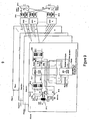
- In the following section a hybrid construction is described where a switch is built with an optical forwarding of a class of quality (GS) and an electronic forwarding of another class of quality (BE). Figure 8 presents a sketch of the building.
- The switch has two switching matrixes, one electronic and one optical switch matrix. The electronic switching matrix is to a great extent similar to today's electronic switches switching matrix, as known from the Prior Art, and works together with the control entity in a manner known from Prior Art "Best Effort" switches.
- The optical switching matrix is supposed to function as a "wavelength router". An inward wavelength is sent to an appointed fibre and outward wavelength. The outward wavelength and the outward fibre are fixed according to the inward wavelength and the inward fibre. As shown in figure 8 At the input the signal is split according to the optical signal's polarization. The advantage of this solution is a pure optical entity which may be used to split the traffic which is supposed to be handled as first priority, and which is supposed to be handled as BE-traffic. The solution presumes that the transmitting party is classifying priority traffic and BE traffic by sending these with orthogonal polarization relatively to each other. The solution may in principle be an addition to the electronic switch wherein the electronic switch is maintained as it is today, and handled "Best effort"-traffic, while the optical wavelength router is handling first priority traffic. The design will then differ from and be less optimal than shown in figure 8. There will be no possibilities for the electronic switch to let the optical switch handle the traffic when the latter has available capacity. The utilization of the optical part will therefore become less optimal; however the design becomes considerably simplified.
- In figure 8 it is thought that a number of wavelengths reserves to the electronic switch and a number to the optical switch. If the optical switch is an addition, this number of wavelengths may be a fixed number, or it may be controlled centrally. If the two switches are built together from the beginning, the number of wavelengths can easier vary and be dynamic and be handled internally in the switch.
- Another design example is given in figure 9. By always delaying packets with high priority (QoS packet), outputs can be reserved so that the destined output is vacant when the packet occurs at the output of the optical buffer.
- In this design BE packets may choose freely among all the wavelengths at the output of the switch. In the first stage be reserved so that the destined output is vacant when the packet occurs at the output of the optical buffer.
- In this design BE packets may choose freely among all the wavelengths at the output of the switch. In the first stage of the switch the output wavelengths is chosen. The QoS packets bypasses this first stage, hence the QoS packets input wavelength will decide the output wavelength at the output fibre. To which output fibre the packet is forwarded, is decided by the wavelength set by the packet switch's second row of wavelength-converters. In the third row of wavelength-converters, the wavelength will be set to a fixed wavelength matching the input wavelength of specific input of a mux. Hence there is not possible changing the wavelength.
- Because there is not possible to buffer the QoS packets for contention resolution in this design, a reservation scheme will be necessary. Before a QoS packet is transmitted, a wavelength from the transmitter to the destination should be reserved. This implies that each of the receivers will simultaneously be able to receive QoS packets from a number of destinations limited to the number of input wavelengths at the receiver end. To avoid contention, no more than one source will be allowed to generate packets to each of the input wavelengths in a node. Figure 10 illustrates this principle.
- In the network shown in figure 10, when QoS information is sent from one node to another, say from node 4, to node 6, a path consisting of one or more wavelengths needs to be reserved all the way through the network, from node 4 to node 6. The reservation implies that no other nodes can transmit QoS information at the reserved wavelength if the wavelengths are sharing the same path (fibre) along the way. If two nodes where transmitting at the same wavelength, contention would occur. Since no buffering is available for QoS packets, packets would have to be node N2, named N2-λ 4, is dropped at N1, and reused for sending QoS packets from node N1 to node N6 (N1-λ 4).
- Normally the node degree in a transport network like this will be in the order of say 4-8. Also the total number of nodes in the transport network will be limited. In COST 266 a reference scenario for a pan European network is given. Figure 11 illustrates this network. In the network a total of 37 Nodes is present, and it has a maximum node degree of 5. The question is whether a static configuration of QoS resources will be sufficiently effective in a transport network. Whether this is true will depend on the amount of QoS traffic in the network, and the number of wavelengths in each node. The packet switch design described will be effective only when a high number of wavelengths are available. This is because the design relies on using the wavelength dimension for contention resolution. Number of wavelengths should therefore be 32 or more
- If a dynamic wavelength allocation scheme is employed, wavelengths can dynamically be set up and taken down on demand. This will increase the utilization of the resources available for transmitting QoS packets, since it will allow dynamic changes in the traffic load. If the node in figure 9. is slightly modified, replacing the fixed wavelength converters at the output with tuneable wavelength converters, the wavelength for a QoS path can be allowed to change along the way. This will allow a higher reuse factor of the wavelengths in the network. However, a technical problem when multiplexing the unpredictable wavelengths at the output of the tuneable wavelength converters has to be solved. Normally a low loss multiplexer will be wavelength sensitive. Other approaches to switching the wavelength in the node may be evaluated. when multiplexing the unpredictable wavelengths at the output of the tuneable wavelength converters has to be solved. Normally a low loss multiplexer will be wavelength sensitive. Other approaches to switching the wavelength in the node may be evaluated.
- The QoS packets do actually not need to be packets. They can be bursts of packets, i.e. burst switching can be performed, or it can be a semi-permanent line, i.e. line switching. It will all depend on the preferred approach. When a QoS packet arrives at the input of the switch, a change in the state of polarisation will be detected. Hence it is known that it is a QoS packet. At the end of a QoS packet, the state of polarisation has to be changed back to the "best effort state" so that when the QoS packet has passed the polarisation monitor, the switch will know the end of the packet. The output and the resources in the switch will then be freed, so that resources can be used by the Best Effort packets.
- Since the start and stop of the QoS packets is detected only by change in state of polarisation, and QoS packets will never be passed to the buffer, there is no need to know the content of the information in the QoS packets. The physical format of the QoS packet, like bitrate and modulation, can therefore in principle be varied. The limitations on the transparency will be set by the characteristics of the wavelength converters.
- For forwarding of the QoS packets, the destination of the packet must be known in advance. This is for the switch to be able to set the wavelength converter in the second row of converters. The information about the QoS packet should be sent in advance. There are two approaches to this:
- 4a) Burst switching approach: This principle should be used if there are few QoS paths in the network, and they will have to be reused often. QoS paths can be established for a very short period of time, corresponding to the length of a packet, or a burst of packets.
The information about the destination for QoS packets occurring at a specific input and wavelength is sent as a control packet. The control packet can be sent on a separate wavelength, or at the same wavelength, and will contain a header, telling the destination of the QoS packet(s). It does not need to contain information about the length of the packet or burst of packets, since the state of polarisation will tell the start and stop of the packets or burst. In burst switching, information about the arrival time of the packet is sent out in advance. This is for the immediate nodes to be able to reserve bandwidth during a, in the control packet, specified period of time. However since the QoS packets are always buffered in the switch in an optical fibre delay line, bandwidth reservation is not necessary in advance, it will be done when the QoS packet arrives at the switch. In addition, a protocol for distribution of the forwarding information will be needed. A table containing a mapping between the address information in the control packet and how to set the wavelength converters is necessary. - 4b) Line switching approach: This principle should be used when QoS paths will have a duration that is much longer than a burst of packets. The output wavelength of the wavelength converter will be set to a wavelength according to a table. The table will be updated by a protocol distributing the forwarding information. This implies that no address lookup will be needed when a QoS packet arrives, avoiding processing. However, there will be a mapping between a specified input (wavelength), and a specified output wavelength, that can be changed only by updating the table. The speed of the dynamic allocation of QoS paths will therefore be limited by the protocol updating of the table.
- The node design in figure 9 allows the QoS paths to be utilized by BE packets when QoS packets are not present. The lights state of polarisation is used for differencing between QoS and BE packets. Therefore, most of the capacity not used by the QoS traffic can be used by the BE packets by interleaving these packets in between the QoS packets or bursts. Technically, it is possible to transmit both QoS and BE packets simultaneously when the polarization is orthogonal. This implies doubling the capacity in the fibre; however this also implies a number of technical challenges with respect to the transmission quality of the signal, since interference between the signals in the two states of polarisation will occur.
- When the node design in figure 9 is used, BE packets can be buffered and allocated a random wavelength along the path to its destination. This allows the capacity of the wavelengths, and also the wavelengths or paths reserved for transmission of QoS packets, to be efficiently utilized. When no QoS packet is present at a reserved QoS path, a BE packet can, if it is available at one of the inputs or in the buffer, be switched to the reserved QoS path.
- When a QoS packet occurs at the input of the switch (node), the packet will be sent in to an optical buffer with a delay corresponding to the length of the longest BE packet. While the QoS packet is in the buffer, the reserved QoS path at the output of the switch will be left vacant from the time when the last packet at this output has left the output until the QoS packet reaches the output of the buffer. The optical buffer will give a predictable delay, thus causing no jitter, with a magnitude insignificant compared to the transmission delay in the fibre between the nodes.
Abbreviation list AWG Arrayed Waveguide Gratings, a component using interferometer principles for wavelength routing or MUX/DEMUX. BE: Best effort BER Bit Error Rate Cw Continuous Wave, laser emitting light, not modulated. D-WRON Dynamic Wavelength Routed Optical Network EDFA Erbium-Doped Fibre Amplifier A form of fibre optical amplification in which the transmitted light signal passes through a section erbium-doped fibre and is amplified by means of a laser pump diode. EDFA is used in transmitter booster amplifiers, in-line repeating amplifiers, and receiver preamplifiers. FDL Fibre Delay Line. FSK Frequency shift keying. A modulation technique for data transmission. It shifts the frequency above the carrier for a 1 and below the carrier for a 0 (zero) GMPLS Generalized Multiprotocol Label Switching GS Guaranteed service. IST EUs 5th program for support of a number of projects. MPLS Multiprotocol label switching, this is a "multiprotocol forwarding standard" describing a method for integration of IP and ATM through label swapping. A IP- and ATM switch, i.e. a MPLS switch, comprises ATM hardware with MPLS software. The software is IP addressing, IP-routing and label distribution protocol. NRZ Non Return to Zero. OCS Optical circuit switched (networks). OPS Optical packet switched (networks). OTDM Optical time division multiplexing. PBS Polarisation Beam Splitter. PC Polarisation Controller PLR Packet Loss Ratio PM Polarizing Maintaining. PMD Polarization Mode Dispersion. A dispersion effect created by irregularities in the shape of the fibre optic cable and it score. Resulting in light propagation at different speeds in the two different modes of polarisation PRBS Pseudo Random Bit Sequence/pattern. A test pattern having the properties of random data (generally 511 or 2047 bits), but generated in such manner that another circuit operating independently, can synchronize on the pattern and detect individual transmission bit errors. QoS Quality of service. RZ Return to Zero. SCM Sub Carrier Modulation combines a signal with a single low frequency sine wave. The low frequency signal is called a subcarrier. This combined signal is then added to a higher frequency radio signal. The resulting high frequency radio signal is very complex and the original signal is not detectable by ordinary means. To detect a signal that has been modulated by a subcarrier, it must be passed through two detector circuits, one to separate the subcarrier from the high frequency radio transmission, and a second to separate the subcarrier from the desired information. SMF Single mode Fibre. SOA Semiconductor Optical Amplifier. SOP States Of Polarisation. S-WRON Static Wavelength Routed Optical Network. WDM Optical Wavelength Division Multiplexing -
- 1. Mike J. O' Mahony et.al. "The application of Optical Packet Switching in Future Communication Networks", IEEE communication Magazine, March 2001, pages 128-135.
- 2. Chunming Qiao et.al. "Labelled Optical Burst Switching for IP-over-WDM Integration" IEEE Communication Magazine, September 2000. Pages 104-114.
- 3. N. Ghani et al. "On IP over WDM integration", IEEE communication magazine, March 2000, pp. 72-83.
- 4. Betti, S.; Curti, F.; De Marchis, G.; Iannone, E Fondazione Ugo Bordoni, Rome, Italy, "A novel multilevel coherent optical system: 4-quadrature signalling" Journal of Lightwave Technology, page(s): 514 - 523 April 1991, Volume: 9 Issue: 4
- 5. Blumenthal, D.J.; Carena, A.; Rau, L.; Curri, V.; Humphries, S. Dept. of Electr. & Comput. Eng., California Univ., Santa Barbara, CA, USA, "WDM optical IP tag switching with packet-rate wavelength conversion and subcarrier multiplexed addressing", Optical Fiber Communication Conference, 1999, and the International Conference on Integrated Optics and Optical Fiber Communication. OFC/IOOC '99. Technical Digest, page(s): 162 - 164 vol.3. 21-26 Feb. 1999
- 6. Xu Lei; Yao Minyu; Cheng Minghua; Zhang Jianfeng; Cheng Xingzhong; Gao Yizhi; Chih-Hsiao Chen, "All optical frame clock extraction with polarization flag in OTDM system", Communications, 1999. APCC/OECC '99. Fifth Asia-Pacific Conference on ... and Fourth Optoelectronics and Communications Conference, 1999 Page(s): 361 -363 vol.1
- 7. Guillemot, et.al. "Transparent optical packet switching: the European ACTS KEOPS project, approach." Journ. Lightwave Techn. 16, pp 2117 -2134, 1998.
- 8. Blumenthal, D.J "Photonic packet and all-optical label switching technologies and techniques"
- 9. OFC 2002 , 17-22 March 2002, pages: 282 -2843
- 10. Sulur, T. K. et.al. "IM/FSK Format for Payload/orthogonal Labelling IP Packets in IP over WDM Networks Supported by GMPLS-based LOBS." ONDM 2003, February 3-5, 2003, Budapest, Hungary.
- 11. Bjornstad et.al. "A highly efficient optical packet switch node design supporting guaranteed service", submitted to ECOC 2003, Sept 21-25 Rimini, Italy.
- 12. J. Hansryd et.al. "Impact of PMD on Four-Wave-Mixing-Induced Crosstalk in WDM Systems." IEEE photonics Technology letters, vol.12, No. 9. September 2000, page 1261-1263.
- 13. M. J. O' Mahony et.al. "The application of optical packet switching in future communication networks", IEEE Comm. Mag., vol. 3, no. 3, pp. 128-135, 2001.
- 14. S. Bjornstad et.al. "A scalable optical packet switch for variable length packets employing shared electronic buffering". ECOC 2002,vol.3,2002. P 4.7
- 15. S. Bjornstad et.al. "QoS differentiation and header/payload separation in optical packet switching using polarisation multiplexing" submitted to ECOC 2003, 2003.
- 16. A. Jukan et.al. "Quality-of-Service Routing in Optical N works" ECOC 97, 1997, pp. 160-163.
Claims (31)
- A communication network arrangement for handling packets within optical or combined optical/electrical packet switched networks, the arrangement comprising at least an ingress node (fig1;1-1) adapted to multiplex optical packets by polarization and an egress node (fig1;1-2) adapted to demultiplex received optical packets by polarization,
characterized in that the ingress node (fig1; 1-1) is further adapted to:transmit packets of a first QoS class in a first state of polarization, and transmit packets of a second QoS in a second state of polarization. - A communication network arrangement according to claim 1,
characterized in that the ingress node is further adapted to:while transmitting said packets of said second QoS in said second state of polarization, simultaneously transmitting a header in said first state of polarization. - A communication network arrangement according to claim 1 or 2,
characterized in that said first and said second states of polarization are interchanged at the beginning of each package. - A communication network arrangement according to any of the preceding claims,
characterized in that the second and first states of polarization are substantially orthogonal states. - A communication network arrangement according to any of the claims 1, 2, or 4
characterized in that the network arrangement further comprises at least one core node (fig3) adapted to;
SOP align received packets,
demultiplex the received packets by polarisation, and
multiplex packets for forwarding by means of polarisation. - A communication network arrangement according to claim 1, 2 or 4,
characterized in that the network arrangement further comprises at least one core node (fig. 3) adapted to demultiplex the received packets by polarisation and to separate packets according to the packets' state of polarisation and the at least one core node (fig. 3) further comprises a first optical switching matrix and a second electronic switching matrix. - A communication network arrangement according to claim 6,
characterized in that the first optical switching matrix is a wavelength router adapted to separate payload of packets of a first QoS class, payload of a second QoS class and header information of the second QoS. - A communication network arrangement according to claim 1, 2 or 4,
characterized in that the network arrangement further comprises at least one core node (fig.3), said core node (fig.3) comprises at least one polarisation beam splitter (PBS1) and at least one optical demultiplexer. - A communication network arrangement according to claim 1, 2 or 4,
characterized in that the network arrangement further comprises at least one core node (fig.3), wherein said at least one core node (fig.3) comprises
two optical demultiplexers,
at least one first wavelength converter,
a second wavelength router, and
at least one third fixed wavelength converter adapted to forward packets of the first and second QoS class to a first optical multiplexer. - A communication network arrangement according to any of the preceding claims,
characterized in that the first. QoS class represents GS-packets and the second QoS class represents BE-packets. - A communication network arrangement according to any of the claims 1, 2 or 9,
characterized in that the ingress node (fig.2) further is adapted to:separate header and payload for BE-packets by means of state of polarisation, andseparate packets by changing state of polarisation at the beginning of every new packet,by means of at least one polarisation beam splitter (PBS) adapted to receive a WDM-signal with a plurality of wavelengths where the polarisation beam splitter (PBS) is adapted to separate header and payload by using the polarization beam splitter per wavelength. - A communication network arrangement according to any of the preceding claims,
characterized in that the arrangement is adapted for use with at least two states of polarisation for signalling traffic. - A communication network arrangement according to any of the claims 5-12,
characterized in that the ingress node and/or the at least one core node comprises an optical packet switched module attached to a S-WRON node. - A communication network arrangement according to any of the claims 1-7, 9; 11,or 12,
characterized in that the network arrangement is adapted to use the derivative of said state of polarisation for separating one or more QoS. - A communication network arrangement according to claim 6,
characterized in that the at least one core node (fig.8) is adapted to switch packets electronically or optically according to which QoS class the packets are associated with. - A communication network arrangement according to claim 15,
characterized in that a number of wavelengths is reserved for the at least one core node of the network adapted to switch packets electronically. - A communication network arrangement according to claim 15,
characterized in that a number of wavelengths is reserved for the at least one core node of the network adapted to switch packets optically. - A method for handling packets within optical or combined optical/electrical packet switched networks comprising at least an ingress node (fig.1;1-1) for multiplexing of optical packets by polarization and an egress node (fig.1;1-2) for demultiplexing of received optical packets by polarization,
characterized by the step of:transmitting packets of a first QoS class in a first state of polarization and transmitting packets of a second QoS in a second state of polarization. - A method according to claim 18,
characterized by transmitting said packets of said second QoS in said second state of polarization while simultaneously transmitting a header associated with the second QoS in said first state of polarization. - A method according to claim 18 or 19,
characterized by interchanging said first and said second states of polarization at the beginning of each package. - A method according to claim 18-20,
characterized in that the second and first state of polarization are substantially orthogonal states. - A method according to claim 18, 19 or 21,
characterized in that the network further comprises at least one core node (fig.3), said core node (fig.3) executing at least one of the following steps:a) demultiplexing received traffic by polarisation, and/orb) polarizing the received traffic, and/orc) SOP-aligning received traffic. - A method according to claim 18, 19 or 21,
characterized in that packets are separated into a first and a second class of quality, wherein packets of the first class is routed using a predefined route within a communication network, and packets of the second class is switched by a packet switch module. - Method according to claim 18 or 20,
characterized in that at the ingress node packets are separated into two classes by setting switches based on header information from said packets. - A method according to claim 20,
characterized in that, at the at least one core node in the optical packet switched network, time divisional multiplexing of received packets is executed. - A method according to claim 22-25,
characterized in that at least one core node (fig.3) in the optical packet switched network is SOP-aligning (fig.3;PC) received packets. - A method according to claim 22,
characterized in that, when a first packet of a first QoS class of the type GS-packet arrives at a switch, the following steps are carried out:a controlling device registering that the first packet is present at the input,then delaying the first packet in a FDL in a first pre-determined period of time, andreserving an output where the first packet is directed to be transmitted. - A method according to claim 27,
characterized by defining the first predefined period of time to be longer than a second period of time, defining the second period of time using a packet with a lower QoS level than the first packet, wherein the second packet is of a maximum allowed size. - A method according to claim 21,
characterized in that statistically multiplexed packets of the second QOS class are interleaved with packets of the first QoS class, and the packets of the first QoS class use a predefined wavelength path within a communication network. - A method according to any of the claims 18-29,
characterized by assigning the first QoS class to GS-packets and assigning the second QoS class to BE-packets. - A method according to claim 30,
characterized by forwarding GS-packets optically using an optical switch and forwarding BE-packets electronically using an electronic switch (fig.8).
Applications Claiming Priority (2)
| Application Number | Priority Date | Filing Date | Title |
|---|---|---|---|
| NO20033075A NO320962B1 (en) | 2003-07-04 | 2003-07-04 | Use of polarization to distinguish different types of information |
| PCT/NO2004/000195 WO2005004363A1 (en) | 2003-07-04 | 2004-06-28 | Use of polarization for differentiation of information |
Publications (2)
| Publication Number | Publication Date |
|---|---|
| EP1652328A1 EP1652328A1 (en) | 2006-05-03 |
| EP1652328B1 true EP1652328B1 (en) | 2007-01-03 |
Family
ID=27800769
Family Applications (1)
| Application Number | Title | Priority Date | Filing Date |
|---|---|---|---|
| EP04748771A Not-in-force EP1652328B1 (en) | 2003-07-04 | 2004-06-28 | Use of polarization for differentiation of information |
Country Status (9)
| Country | Link |
|---|---|
| US (2) | US8073328B2 (en) |
| EP (1) | EP1652328B1 (en) |
| JP (1) | JP2007527638A (en) |
| KR (1) | KR20060114315A (en) |
| CN (1) | CN1842984A (en) |
| AT (1) | ATE350825T1 (en) |
| DE (1) | DE602004004151T2 (en) |
| NO (1) | NO320962B1 (en) |
| WO (1) | WO2005004363A1 (en) |
Cited By (1)
| Publication number | Priority date | Publication date | Assignee | Title |
|---|---|---|---|---|
| WO2014139438A1 (en) | 2013-03-15 | 2014-09-18 | Huawei Technologies Co., Ltd. | System and method for steering packet streams |
Families Citing this family (39)
| Publication number | Priority date | Publication date | Assignee | Title |
|---|---|---|---|---|
| NO320962B1 (en) * | 2003-07-04 | 2006-02-20 | Telenor Asa | Use of polarization to distinguish different types of information |
| KR100602269B1 (en) * | 2004-11-02 | 2006-07-19 | 삼성전자주식회사 | The optical packet communication system using the labling of the wavelength-offset polarization-division multiplexing |
| JP4638754B2 (en) * | 2005-03-18 | 2011-02-23 | 富士通株式会社 | Optical device and optical cross-connect device |
| WO2007003932A2 (en) * | 2005-07-01 | 2007-01-11 | Ntnu Technology Transfer As | Packet switched networks |
| NO20053902L (en) * | 2005-08-19 | 2007-02-20 | Telenor Asa | Method and system for signaling in an optical packet switched network |
| US7920790B2 (en) * | 2006-09-08 | 2011-04-05 | Telcordia Technologies, Inc. | Polarization envelope modulation for signaling and labeling in optical networks |
| MX2010003928A (en) | 2007-10-11 | 2010-09-10 | Philip Morris Prod | Smokeless tobacco product. |
| JP5545752B2 (en) * | 2010-12-20 | 2014-07-09 | 富士通テレコムネットワークス株式会社 | Optical packet switching system |
| GB201101709D0 (en) | 2011-02-01 | 2011-03-16 | Transpacket As | A method and a node arrangement for optimizing traffic processing in integrated hybrid networks |
| US8891963B2 (en) * | 2011-09-09 | 2014-11-18 | Evertz Microsystems Ltd. | Hybrid signal router |
| US9136969B2 (en) | 2012-01-27 | 2015-09-15 | Futurewei Technologies, Inc. | Spectral encoding of an optical label or destination |
| EP2685653A1 (en) * | 2012-07-11 | 2014-01-15 | Xieon Networks S.à.r.l. | Method and device for signal processing in an optical communication network |
| US9123190B2 (en) * | 2013-01-31 | 2015-09-01 | Eastman Kodak Company | Method for authenticating an object |
| CN105637821B (en) * | 2013-10-22 | 2020-06-05 | 慧与发展有限责任合伙企业 | Hybrid circuit-packet switch |
| JP6458560B2 (en) * | 2015-03-06 | 2019-01-30 | 富士通株式会社 | Wavelength allocation method and wavelength allocation apparatus |
| CN104897997B (en) * | 2015-06-12 | 2016-10-26 | 广东电网有限责任公司电力科学研究院 | A kind of digitalized electric energy metering communication analog |
| US10015568B2 (en) * | 2016-10-11 | 2018-07-03 | Fluke Corporation | Optically-addressable optical switch |
| GB201711293D0 (en) | 2017-07-13 | 2017-08-30 | Transpacket As | Packet-based communication |
| US10601520B2 (en) | 2018-02-07 | 2020-03-24 | Infinera Corporation | Clock recovery for digital subcarriers for optical networks |
| US11368228B2 (en) | 2018-04-13 | 2022-06-21 | Infinera Corporation | Apparatuses and methods for digital subcarrier parameter modifications for optical communication networks |
| US11095389B2 (en) | 2018-07-12 | 2021-08-17 | Infiriera Corporation | Subcarrier based data center network architecture |
| CN109451377B (en) * | 2018-11-28 | 2021-07-27 | 杭州电子科技大学 | Optical switch based on integrated hybrid switching technology |
| US11258528B2 (en) | 2019-09-22 | 2022-02-22 | Infinera Corporation | Frequency division multiple access optical subcarriers |
| US11075694B2 (en) | 2019-03-04 | 2021-07-27 | Infinera Corporation | Frequency division multiple access optical subcarriers |
| US11336369B2 (en) | 2019-03-22 | 2022-05-17 | Infinera Corporation | Framework for handling signal integrity using ASE in optical networks |
| US10965439B2 (en) | 2019-04-19 | 2021-03-30 | Infinera Corporation | Synchronization for subcarrier communication |
| US11838105B2 (en) | 2019-05-07 | 2023-12-05 | Infinera Corporation | Bidirectional optical communications |
| US11476966B2 (en) | 2019-05-14 | 2022-10-18 | Infinera Corporation | Out-of-band communication channel for subcarrier-based optical communication systems |
| US11088764B2 (en) * | 2019-05-14 | 2021-08-10 | Infinera Corporation | Out-of-band communication channel for sub-carrier-based optical communication systems |
| US11190291B2 (en) | 2019-05-14 | 2021-11-30 | Infinera Corporation | Out-of-band communication channel for subcarrier-based optical communication systems |
| US11489613B2 (en) | 2019-05-14 | 2022-11-01 | Infinera Corporation | Out-of-band communication channel for subcarrier-based optical communication systems |
| US11239935B2 (en) * | 2019-05-14 | 2022-02-01 | Infinera Corporation | Out-of-band communication channel for subcarrier-based optical communication systems |
| US11296812B2 (en) | 2019-05-14 | 2022-04-05 | Infinera Corporation | Out-of-band communication channel for subcarrier-based optical communication systems |
| KR102128201B1 (en) | 2019-06-18 | 2020-06-29 | 연세대학교 산학협력단 | Differential polarization Shift Keying based Optical Transmitter/Receiver and Method thereof |
| US11122347B2 (en) * | 2019-07-01 | 2021-09-14 | Google Llc | Reconfigurable computing pods using optical networks with one-to-many optical switches |
| US11297005B2 (en) | 2019-09-05 | 2022-04-05 | Infiriera Corporation | Dynamically switching queueing schemes for network switches |
| EP4042607A1 (en) | 2019-10-10 | 2022-08-17 | Infinera Corporation | Network switches systems for optical communications networks |
| US20210111802A1 (en) | 2019-10-10 | 2021-04-15 | Infinera Corporation | Hub-leaf laser synchronization |
| AU2020364088A1 (en) | 2019-10-10 | 2022-05-12 | Infinera Corporation | Optical subcarrier dual-path protection and restoration for optical communications networks |
Family Cites Families (17)
| Publication number | Priority date | Publication date | Assignee | Title |
|---|---|---|---|---|
| NL1005263C2 (en) * | 1996-03-06 | 1997-09-09 | Nederland Ptt | Optical packet-switched transmission network. |
| US5946116A (en) * | 1997-04-02 | 1999-08-31 | Wu; Kuang-Yi | 1 X N digitally programmable optical routing switch |
| US6934471B1 (en) * | 1999-06-03 | 2005-08-23 | Avici Systems, Inc. | Photonic switch using time-slot interchange |
| US6819872B2 (en) * | 1999-06-23 | 2004-11-16 | Jds Uniphase Corporation | Micro-optic delay element for use in a time division multiplexed system |
| US20010048556A1 (en) * | 1999-11-29 | 2001-12-06 | Ranalli Eliseo R. | Wavelength selective switch |
| US6580535B1 (en) * | 1999-12-28 | 2003-06-17 | Telefonaktiebolaget Lm Ericsson (Publ) | Polarization division multiplexing in optical data transmission systems |
| US7058974B1 (en) * | 2000-06-21 | 2006-06-06 | Netrake Corporation | Method and apparatus for preventing denial of service attacks |
| US7298704B2 (en) * | 2000-07-06 | 2007-11-20 | Lucent Technologies Inc. | Dynamic path routing with service level guarantees in optical networks |
| US6459827B1 (en) * | 2000-10-02 | 2002-10-01 | John N. Hait | Polarization-stabilizing, phase-and-polarization-insensitive, photonic data router |
| JP2002300181A (en) * | 2001-03-30 | 2002-10-11 | Nec Corp | INTEGRATED NETWORK QoS CONTROL SYSTEM |
| US20030026250A1 (en) * | 2001-08-03 | 2003-02-06 | Xiaojun Fang | Method and device for synchronous cell transfer and circuit-packet duality switching |
| US7106967B2 (en) * | 2001-09-04 | 2006-09-12 | Doron Handelman | Optical packet switching apparatus and methods |
| DE10147892B4 (en) * | 2001-09-28 | 2004-02-05 | Siemens Ag | Method for transmitting at least one first and second data signal in polarization multiplex in an optical transmission system |
| KR100452945B1 (en) * | 2002-01-07 | 2004-10-14 | 학교법인 한국정보통신학원 | Dynamic Wavelength Management Method in OBS Networks |
| DE10212649B4 (en) * | 2002-03-21 | 2004-02-12 | Siemens Ag | Cross connector for optical signals |
| US7209670B2 (en) * | 2003-04-29 | 2007-04-24 | Nortel Networks Limited | Polarization diversity receiver for optical transmission system |
| NO320962B1 (en) * | 2003-07-04 | 2006-02-20 | Telenor Asa | Use of polarization to distinguish different types of information |
-
2003
- 2003-07-04 NO NO20033075A patent/NO320962B1/en not_active IP Right Cessation
-
2004
- 2004-06-28 CN CNA200480024561XA patent/CN1842984A/en active Pending
- 2004-06-28 AT AT04748771T patent/ATE350825T1/en not_active IP Right Cessation
- 2004-06-28 JP JP2006518569A patent/JP2007527638A/en active Pending
- 2004-06-28 DE DE602004004151T patent/DE602004004151T2/en active Active
- 2004-06-28 EP EP04748771A patent/EP1652328B1/en not_active Not-in-force
- 2004-06-28 KR KR1020067000245A patent/KR20060114315A/en not_active Application Discontinuation
- 2004-06-28 US US10/563,494 patent/US8073328B2/en not_active Expired - Fee Related
- 2004-06-28 WO PCT/NO2004/000195 patent/WO2005004363A1/en active IP Right Grant
-
2011
- 2011-10-26 US US13/282,258 patent/US9071381B2/en not_active Expired - Fee Related
Cited By (3)
| Publication number | Priority date | Publication date | Assignee | Title |
|---|---|---|---|---|
| WO2014139438A1 (en) | 2013-03-15 | 2014-09-18 | Huawei Technologies Co., Ltd. | System and method for steering packet streams |
| EP2962417A4 (en) * | 2013-03-15 | 2016-03-16 | Huawei Tech Co Ltd | System and method for steering packet streams |
| US10015111B2 (en) | 2013-03-15 | 2018-07-03 | Huawei Technologies Co., Ltd. | System and method for steering packet streams |
Also Published As
| Publication number | Publication date |
|---|---|
| NO320962B1 (en) | 2006-02-20 |
| DE602004004151D1 (en) | 2007-02-15 |
| CN1842984A (en) | 2006-10-04 |
| US20060159454A1 (en) | 2006-07-20 |
| US8073328B2 (en) | 2011-12-06 |
| NO20033075D0 (en) | 2003-07-04 |
| KR20060114315A (en) | 2006-11-06 |
| JP2007527638A (en) | 2007-09-27 |
| US9071381B2 (en) | 2015-06-30 |
| WO2005004363A1 (en) | 2005-01-13 |
| EP1652328A1 (en) | 2006-05-03 |
| NO20033075L (en) | 2005-01-05 |
| ATE350825T1 (en) | 2007-01-15 |
| US20120039601A1 (en) | 2012-02-16 |
| DE602004004151T2 (en) | 2008-03-20 |
Similar Documents
| Publication | Publication Date | Title |
|---|---|---|
| EP1652328B1 (en) | Use of polarization for differentiation of information | |
| US10506311B2 (en) | System and method for optical network | |
| US7162155B2 (en) | Optical packet switching apparatus and methods | |
| US20030147585A1 (en) | Equipments including transponder for optical fiber transmission | |
| JP4969473B2 (en) | Optical access network and optical communication path switching control system | |
| EP1600029B1 (en) | Architecture, method and system of wdm-based photonic burst switched networks | |
| KR20040070691A (en) | High capacity router employing electrical buffer memory | |
| Maier et al. | A hybrid MAC protocol for a metro WDM network using multiple free spectral ranges of an arrayed-waveguide grating | |
| Choa et al. | An optical packet switch based on WDM technologies | |
| US20100111526A1 (en) | Communications node for and method of routing optical data packet signals | |
| JP5614482B1 (en) | Station side terminal device and path switching method | |
| Okada et al. | All-optical packet routing by an out-of-band optical label and wavelength conversion in a full-mesh network based on a cyclic-frequency AWG | |
| KR101069977B1 (en) | Communication device and communication method | |
| US6782200B1 (en) | Packet-based optical communications networks | |
| KR20120074357A (en) | Passive optical network apparatus for transmitting optical signal | |
| Richter et al. | Field trial of an ASON in the metropolitan area | |
| Chan et al. | Node architecture and protocol of a packet-switched dense WDMA metropolitan area network | |
| US20020109880A1 (en) | Method and apparatus for switching wavelength-division-multiplexed optical signals | |
| KR100565943B1 (en) | Optical packet label switching system based on the wavelength band path | |
| Miyazawa et al. | Optical access architecture designs based on WDM-direct toward new generation networks | |
| Willner et al. | 3.3 Photonic Networks | |
| Wada et al. | Optical integrated network technologies for coping with traffic fluctuation and service diversification | |
| Yoo | Optical burst and packet switching | |
| KR100281419B1 (en) | Fully Optical Packet Switching System | |
| Ali et al. | Analyzing Wavelength Conversion and Traffic Grooming in Optical WDM Networks |
Legal Events
| Date | Code | Title | Description |
|---|---|---|---|
| PUAI | Public reference made under article 153(3) epc to a published international application that has entered the european phase |
Free format text: ORIGINAL CODE: 0009012 |
|
| 17P | Request for examination filed |
Effective date: 20060131 |
|
| AK | Designated contracting states |
Kind code of ref document: A1 Designated state(s): AT BE BG CH CY CZ DE DK EE ES FI FR GB GR HU IE IT LI LU MC NL PL PT RO SE SI SK TR |
|
| GRAP | Despatch of communication of intention to grant a patent |
Free format text: ORIGINAL CODE: EPIDOSNIGR1 |
|
| DAX | Request for extension of the european patent (deleted) | ||
| GRAS | Grant fee paid |
Free format text: ORIGINAL CODE: EPIDOSNIGR3 |
|
| GRAA | (expected) grant |
Free format text: ORIGINAL CODE: 0009210 |
|
| AK | Designated contracting states |
Kind code of ref document: B1 Designated state(s): AT BE BG CH CY CZ DE DK EE ES FI FR GB GR HU IE IT LI LU MC NL PL PT RO SE SI SK TR |
|
| PG25 | Lapsed in a contracting state [announced via postgrant information from national office to epo] |
Ref country code: SI Free format text: LAPSE BECAUSE OF FAILURE TO SUBMIT A TRANSLATION OF THE DESCRIPTION OR TO PAY THE FEE WITHIN THE PRESCRIBED TIME-LIMIT Effective date: 20070103 Ref country code: FI Free format text: LAPSE BECAUSE OF FAILURE TO SUBMIT A TRANSLATION OF THE DESCRIPTION OR TO PAY THE FEE WITHIN THE PRESCRIBED TIME-LIMIT Effective date: 20070103 Ref country code: PL Free format text: LAPSE BECAUSE OF FAILURE TO SUBMIT A TRANSLATION OF THE DESCRIPTION OR TO PAY THE FEE WITHIN THE PRESCRIBED TIME-LIMIT Effective date: 20070103 Ref country code: LI Free format text: LAPSE BECAUSE OF FAILURE TO SUBMIT A TRANSLATION OF THE DESCRIPTION OR TO PAY THE FEE WITHIN THE PRESCRIBED TIME-LIMIT Effective date: 20070103 Ref country code: CH Free format text: LAPSE BECAUSE OF FAILURE TO SUBMIT A TRANSLATION OF THE DESCRIPTION OR TO PAY THE FEE WITHIN THE PRESCRIBED TIME-LIMIT Effective date: 20070103 Ref country code: AT Free format text: LAPSE BECAUSE OF FAILURE TO SUBMIT A TRANSLATION OF THE DESCRIPTION OR TO PAY THE FEE WITHIN THE PRESCRIBED TIME-LIMIT Effective date: 20070103 Ref country code: DK Free format text: LAPSE BECAUSE OF FAILURE TO SUBMIT A TRANSLATION OF THE DESCRIPTION OR TO PAY THE FEE WITHIN THE PRESCRIBED TIME-LIMIT Effective date: 20070103 Ref country code: NL Free format text: LAPSE BECAUSE OF FAILURE TO SUBMIT A TRANSLATION OF THE DESCRIPTION OR TO PAY THE FEE WITHIN THE PRESCRIBED TIME-LIMIT Effective date: 20070103 |
|
| REG | Reference to a national code |
Ref country code: GB Ref legal event code: FG4D |
|
| REF | Corresponds to: |
Ref document number: 602004004151 Country of ref document: DE Date of ref document: 20070215 Kind code of ref document: P |
|
| REG | Reference to a national code |
Ref country code: IE Ref legal event code: FG4D |
|
| PG25 | Lapsed in a contracting state [announced via postgrant information from national office to epo] |
Ref country code: SE Free format text: LAPSE BECAUSE OF FAILURE TO SUBMIT A TRANSLATION OF THE DESCRIPTION OR TO PAY THE FEE WITHIN THE PRESCRIBED TIME-LIMIT Effective date: 20070403 Ref country code: BG Free format text: LAPSE BECAUSE OF FAILURE TO SUBMIT A TRANSLATION OF THE DESCRIPTION OR TO PAY THE FEE WITHIN THE PRESCRIBED TIME-LIMIT Effective date: 20070403 |
|
| PG25 | Lapsed in a contracting state [announced via postgrant information from national office to epo] |
Ref country code: ES Free format text: LAPSE BECAUSE OF FAILURE TO SUBMIT A TRANSLATION OF THE DESCRIPTION OR TO PAY THE FEE WITHIN THE PRESCRIBED TIME-LIMIT Effective date: 20070414 |
|
| PG25 | Lapsed in a contracting state [announced via postgrant information from national office to epo] |
Ref country code: PT Free format text: LAPSE BECAUSE OF FAILURE TO SUBMIT A TRANSLATION OF THE DESCRIPTION OR TO PAY THE FEE WITHIN THE PRESCRIBED TIME-LIMIT Effective date: 20070604 |
|
| ET | Fr: translation filed | ||
| NLV1 | Nl: lapsed or annulled due to failure to fulfill the requirements of art. 29p and 29m of the patents act | ||
| REG | Reference to a national code |
Ref country code: CH Ref legal event code: PL |
|
| PLBE | No opposition filed within time limit |
Free format text: ORIGINAL CODE: 0009261 |
|
| STAA | Information on the status of an ep patent application or granted ep patent |
Free format text: STATUS: NO OPPOSITION FILED WITHIN TIME LIMIT |
|
| PG25 | Lapsed in a contracting state [announced via postgrant information from national office to epo] |
Ref country code: SK Free format text: LAPSE BECAUSE OF FAILURE TO SUBMIT A TRANSLATION OF THE DESCRIPTION OR TO PAY THE FEE WITHIN THE PRESCRIBED TIME-LIMIT Effective date: 20070103 |
|
| 26N | No opposition filed |
Effective date: 20071005 |
|
| PG25 | Lapsed in a contracting state [announced via postgrant information from national office to epo] |
Ref country code: RO Free format text: LAPSE BECAUSE OF FAILURE TO SUBMIT A TRANSLATION OF THE DESCRIPTION OR TO PAY THE FEE WITHIN THE PRESCRIBED TIME-LIMIT Effective date: 20070103 Ref country code: BE Free format text: LAPSE BECAUSE OF FAILURE TO SUBMIT A TRANSLATION OF THE DESCRIPTION OR TO PAY THE FEE WITHIN THE PRESCRIBED TIME-LIMIT Effective date: 20070103 Ref country code: CZ Free format text: LAPSE BECAUSE OF FAILURE TO SUBMIT A TRANSLATION OF THE DESCRIPTION OR TO PAY THE FEE WITHIN THE PRESCRIBED TIME-LIMIT Effective date: 20070103 |
|
| PG25 | Lapsed in a contracting state [announced via postgrant information from national office to epo] |
Ref country code: MC Free format text: LAPSE BECAUSE OF NON-PAYMENT OF DUE FEES Effective date: 20070630 |
|
| PG25 | Lapsed in a contracting state [announced via postgrant information from national office to epo] |
Ref country code: IT Free format text: LAPSE BECAUSE OF FAILURE TO SUBMIT A TRANSLATION OF THE DESCRIPTION OR TO PAY THE FEE WITHIN THE PRESCRIBED TIME-LIMIT Effective date: 20070103 Ref country code: GR Free format text: LAPSE BECAUSE OF FAILURE TO SUBMIT A TRANSLATION OF THE DESCRIPTION OR TO PAY THE FEE WITHIN THE PRESCRIBED TIME-LIMIT Effective date: 20070404 |
|
| PG25 | Lapsed in a contracting state [announced via postgrant information from national office to epo] |
Ref country code: IE Free format text: LAPSE BECAUSE OF NON-PAYMENT OF DUE FEES Effective date: 20070628 |
|
| PG25 | Lapsed in a contracting state [announced via postgrant information from national office to epo] |
Ref country code: EE Free format text: LAPSE BECAUSE OF FAILURE TO SUBMIT A TRANSLATION OF THE DESCRIPTION OR TO PAY THE FEE WITHIN THE PRESCRIBED TIME-LIMIT Effective date: 20070103 |
|
| GBPC | Gb: european patent ceased through non-payment of renewal fee |
Effective date: 20080628 |
|
| PG25 | Lapsed in a contracting state [announced via postgrant information from national office to epo] |
Ref country code: GB Free format text: LAPSE BECAUSE OF NON-PAYMENT OF DUE FEES Effective date: 20080628 |
|
| PG25 | Lapsed in a contracting state [announced via postgrant information from national office to epo] |
Ref country code: CY Free format text: LAPSE BECAUSE OF FAILURE TO SUBMIT A TRANSLATION OF THE DESCRIPTION OR TO PAY THE FEE WITHIN THE PRESCRIBED TIME-LIMIT Effective date: 20070103 |
|
| PG25 | Lapsed in a contracting state [announced via postgrant information from national office to epo] |
Ref country code: LU Free format text: LAPSE BECAUSE OF NON-PAYMENT OF DUE FEES Effective date: 20070628 |
|
| PG25 | Lapsed in a contracting state [announced via postgrant information from national office to epo] |
Ref country code: TR Free format text: LAPSE BECAUSE OF FAILURE TO SUBMIT A TRANSLATION OF THE DESCRIPTION OR TO PAY THE FEE WITHIN THE PRESCRIBED TIME-LIMIT Effective date: 20070103 Ref country code: HU Free format text: LAPSE BECAUSE OF FAILURE TO SUBMIT A TRANSLATION OF THE DESCRIPTION OR TO PAY THE FEE WITHIN THE PRESCRIBED TIME-LIMIT Effective date: 20070704 |
|
| REG | Reference to a national code |
Ref country code: GB Ref legal event code: S28 Free format text: APPLICATION FILED |
|
| REG | Reference to a national code |
Ref country code: GB Ref legal event code: 732E Free format text: REGISTERED BETWEEN 20091119 AND 20091125 |
|
| REG | Reference to a national code |
Ref country code: GB Ref legal event code: S28 Free format text: RESTORATION ALLOWED Effective date: 20100803 |
|
| REG | Reference to a national code |
Ref country code: FR Ref legal event code: TP |
|
| REG | Reference to a national code |
Ref country code: DE Ref legal event code: R081 Ref document number: 602004004151 Country of ref document: DE Owner name: TRANSPACKET AS, NO Free format text: FORMER OWNER: TELENOR ASA, FORNEBU, NO Effective date: 20110218 |
|
| REG | Reference to a national code |
Ref country code: GB Ref legal event code: 732E Free format text: REGISTERED BETWEEN 20130418 AND 20130424 |
|
| REG | Reference to a national code |
Ref country code: FR Ref legal event code: PLFP Year of fee payment: 13 |
|
| REG | Reference to a national code |
Ref country code: FR Ref legal event code: PLFP Year of fee payment: 14 |
|
| REG | Reference to a national code |
Ref country code: FR Ref legal event code: PLFP Year of fee payment: 15 |
|
| PGFP | Annual fee paid to national office [announced via postgrant information from national office to epo] |
Ref country code: FR Payment date: 20210610 Year of fee payment: 18 |
|
| PGFP | Annual fee paid to national office [announced via postgrant information from national office to epo] |
Ref country code: DE Payment date: 20210812 Year of fee payment: 18 |
|
| PGFP | Annual fee paid to national office [announced via postgrant information from national office to epo] |
Ref country code: GB Payment date: 20220617 Year of fee payment: 19 |
|
| REG | Reference to a national code |
Ref country code: DE Ref legal event code: R119 Ref document number: 602004004151 Country of ref document: DE |
|
| PG25 | Lapsed in a contracting state [announced via postgrant information from national office to epo] |
Ref country code: FR Free format text: LAPSE BECAUSE OF NON-PAYMENT OF DUE FEES Effective date: 20220630 |
|
| PG25 | Lapsed in a contracting state [announced via postgrant information from national office to epo] |
Ref country code: DE Free format text: LAPSE BECAUSE OF NON-PAYMENT OF DUE FEES Effective date: 20230103 |
|
| GBPC | Gb: european patent ceased through non-payment of renewal fee |
Effective date: 20230628 |
|
| PG25 | Lapsed in a contracting state [announced via postgrant information from national office to epo] |
Ref country code: GB Free format text: LAPSE BECAUSE OF NON-PAYMENT OF DUE FEES Effective date: 20230628 |