EP1650635A1 - Computer housing with removable light pipe - Google Patents
Computer housing with removable light pipe Download PDFInfo
- Publication number
- EP1650635A1 EP1650635A1 EP05256175A EP05256175A EP1650635A1 EP 1650635 A1 EP1650635 A1 EP 1650635A1 EP 05256175 A EP05256175 A EP 05256175A EP 05256175 A EP05256175 A EP 05256175A EP 1650635 A1 EP1650635 A1 EP 1650635A1
- Authority
- EP
- European Patent Office
- Prior art keywords
- door assembly
- light pipe
- drive
- computer housing
- optical conductor
- Prior art date
- Legal status (The legal status is an assumption and is not a legal conclusion. Google has not performed a legal analysis and makes no representation as to the accuracy of the status listed.)
- Granted
Links
Images


Classifications
-
- G—PHYSICS
- G11—INFORMATION STORAGE
- G11B—INFORMATION STORAGE BASED ON RELATIVE MOVEMENT BETWEEN RECORD CARRIER AND TRANSDUCER
- G11B33/00—Constructional parts, details or accessories not provided for in the other groups of this subclass
- G11B33/02—Cabinets; Cases; Stands; Disposition of apparatus therein or thereon
- G11B33/027—Covers
-
- G—PHYSICS
- G06—COMPUTING; CALCULATING OR COUNTING
- G06F—ELECTRIC DIGITAL DATA PROCESSING
- G06F1/00—Details not covered by groups G06F3/00 - G06F13/00 and G06F21/00
- G06F1/16—Constructional details or arrangements
- G06F1/18—Packaging or power distribution
-
- G—PHYSICS
- G06—COMPUTING; CALCULATING OR COUNTING
- G06F—ELECTRIC DIGITAL DATA PROCESSING
- G06F1/00—Details not covered by groups G06F3/00 - G06F13/00 and G06F21/00
- G06F1/16—Constructional details or arrangements
- G06F1/18—Packaging or power distribution
- G06F1/181—Enclosures
-
- G—PHYSICS
- G11—INFORMATION STORAGE
- G11B—INFORMATION STORAGE BASED ON RELATIVE MOVEMENT BETWEEN RECORD CARRIER AND TRANSDUCER
- G11B33/00—Constructional parts, details or accessories not provided for in the other groups of this subclass
- G11B33/12—Disposition of constructional parts in the apparatus, e.g. of power supply, of modules
- G11B33/121—Disposition of constructional parts in the apparatus, e.g. of power supply, of modules the apparatus comprising a single recording/reproducing device
- G11B33/122—Arrangements for providing electrical connections, e.g. connectors, cables, switches
Definitions
- An embodiment of the present invention relates to the field of housings for computers. More specifically, embodiments of the present invention relate to a computer housing with a removable light pipe.
- Computers such as a personal computer (PC), workstation computers, etc. and similar electronic apparatus, instruments, etc. are typically housed in a protective structure. Such computer housings function to protect and support components of the computer within their enclosure. Protection is provided against moisture, dirt, dust, and other environmental contaminants, and potentially disturbing mechanical and electrical contact with outside objects.
- PC personal computer
- workstation computers etc.
- similar electronic apparatus, instruments, etc. are typically housed in a protective structure.
- Such computer housings function to protect and support components of the computer within their enclosure. Protection is provided against moisture, dirt, dust, and other environmental contaminants, and potentially disturbing mechanical and electrical contact with outside objects.
- a variety of conventional light pipes may be installable with a particular conventional computer housing. Not all of the various light pipes will function properly in a particular installation. However, conventional light pipes are not labeled for a designated installation. This can cause confusion, mis-selection, and mis-installation (e.g., choosing the incorrect light pipe for a particular installation and installing the incorrect light pipe in that installation).
- Conventional light pipes can be installed with conventional computer housings in several possible configurations. However, not all of the possible configurations will allow the conventional light pipe to function properly in a particular installation. Once installed, reconfiguring the mis-configured light pipe into the correct configuration for that light pipe in that installation requires removal of the mis-configured, thus mis-installed light pipe. As discussed above, this can cause damage to the light pipe, to another computer housing component, or both.
- Figure 1 depicts an exemplary computer housing, according to an embodiment of the present invention, from an outer perspective.
- Figure 2 depicts an exemplary computer housing, according to an embodiment of the present invention, from an exploded perspective.
- Figure 7 depicts an exemplary front panel for a computer housing with multiple drives installed, according to an embodiment of the present invention, from a rear perspective.
- Figure 1 depicts an exemplary computer housing 10, according to an embodiment of the present invention, from an outer perspective.
- Computer housing 10 has a front panel 11.
- Front panel 11 couples with a case 16 and functions as a protective front surface for computer housing 11, which allows users to access and interface with components internal to the computer housing 11, such as drives.
- embodiments of the present invention may be practiced with functionality, exemplified herein with reference to front panel 11, wherein the computer housing is configured, oriented, etc. in such a way that the functionality is oriented to an aspect (e.g., direction, position, orientation, etc.) other than the front of the computer housing.
- the computer housing exemplified herein with reference to computer housing 10 can have any shape, size, configuration, orientation, etc., and can house any kind of computer, instrument, electronic apparatus, etc.
- Drive 22 is a drive for an optical medium such as a compact disk (CD), a digital versatile disk (DVD) with which data and program storage and/or retrieval such as reading, writing, and read/write operations, etc. can be performed.
- Drive 22 has a light emitting diode (LED) 25, which illuminates to indicate an operation thereof. For instance, LED 25 can illuminate responsive to drive 22 performing a read or a write operation, etc.
- LED light emitting diode
- drive door assembly 18 With front panel 11 in place with case 16, drive door assembly 18 is positioned proximate to drive 22 such that indicator 15 provides indication responsive to LED 25 illuminating, which displays the indication provided by LED 25 outside of computer housing 10, e.g., in front of front panel 11. With front panel 11 in place with case 16, drive door assembly 18 is positioned proximate to drive 22 such that indicator 15 is proximate to a position P on drive 22, which is a distance D away from LED 25.
- Drive door assembly has a light pipe 30 for transmitting light emitted by LED 25 (Fig. 2) to indicator 15 (Fig. 1, 2).
- drive door assembly 18 With front panel 11 in place with case 16, drive door assembly 18 is positioned such that light pipe 30 conducts light emitted by LED 25 at position P' to be displayed with indicator 15 at position P. From the perspective depicted, one end of light pipe 30 covers indicator 15 at position P and its other end faces position P'.
- Light pipe 30 thus has a length corresponding to the distance D, e.g., the horizontal distance between LED 25 and indicator 15 with respect to front panel 11.
- drive door assembly 18 couples light pipe 30 securely with door assembly 15
- light pipe 30 and door assembly 15 are coupled such that light pipe 30 can be readily, e.g., easily, quickly, with little effort, and without damage to either, decoupled therefrom.
- light pipe 30 has a key 57, which can be of integral construction with optical conductor 40 and/or appurtenant thereto. Key 57 functions with optical conductor 40 to couple the optical conductor 40 with the door assembly 15 in a configuration wherein end 42 is coupled with a first location on door assembly 15, e.g., proximate to position P' conforming to LED 25, and wherein end 41 is coupled with a second location on the door assembly, e.g., proximate to position P conforming to indicator 14.
- light pipe 30 comprises one of a plurality of different light pipes, each for example correspondingly labeled by a distinctive (e.g., different, individual, etc.) label 43 (Fig. 4) and each having a distinctive key 57.
- structural feature 58 is correspondingly distinctive and functions with key 57 to couple only the proper light pipe 30 for a particular door assembly 15, in their proper configuration.
- Figure 6 depicts an exemplary computer housing 60 with multiple drive door assemblies 61 and 62 installed, according to an embodiment of the present invention, from an outer perspective.
- Computer housing 60 has a front panel 69.
- Front panel 69 couples with case 16 and functions as a protective front surface for computer housing 60, which allows users to access and interface with components such as drives, which are internal to the computer housing 60.
- Drive door assemblies 61 and 62 allow accessing and interfacing with internal drives and can be a component of, integral with, etc. front panel 69.
- step 83 the light pipe is aligned to couple with the drive door assembly in a single configuration.
- coupling the light pipe with the drive door assembly in any other configuration is deterred, e.g., by one or more structural features of the light pipe and/or the drive door assembly.
Abstract
Description
- An embodiment of the present invention relates to the field of housings for computers. More specifically, embodiments of the present invention relate to a computer housing with a removable light pipe.
- Computers such as a personal computer (PC), workstation computers, etc. and similar electronic apparatus, instruments, etc. are typically housed in a protective structure. Such computer housings function to protect and support components of the computer within their enclosure. Protection is provided against moisture, dirt, dust, and other environmental contaminants, and potentially disturbing mechanical and electrical contact with outside objects.
- For instance, modern computer components such as processors, memory, etc. typically comprise field effect transistors and other devices that tend to be very sensitive to damage with spurious electrostatic discharges. Thus, computer housings are typically electrically grounded, and may also so function as a convenient chassis based ground reference for some electrical components of the computer housed therein. Further, in as much as some electrical components of the computer housed within can operate at hazardous voltage levels, in ensconcing the components, computer housings provide the added beneficial function of isolating them from outside, thus protecting humans from dangerous accidental contact therewith.
- Computer housings typically have a case for enclosing the computer and a sturdy frame which supports the case and components of the computer. The case can have a number of panels, such as a front and a back, a top and a bottom, and a left and a right side, etc. On some computer housings, one or more of the panels, e.g., the front panel, can provide access, indication, and/or interfacing with computer components internal to the computer housing, e.g., supported by its frame.
- Common computer components include drives for accessing removable media, such as to store and/or retrieve data and/or programs, etc. thereon. Such drives can include magnetic drives and optical drives. Optical drives allow the computer to function with optical media such as a compact disk (CD), a digital versatile dick (DVD), etc. Typical optical drives are accessed by mechanically, electromechanically, etc. operating an eject button, which allows the optical medium to be installed and/or removed from the drive and provide indication relating to an operation of the drive with a light emitting diode (LED).
- Computer housings, e.g., a front panel thereof, allow the eject button to be operated by a user, e.g., by actuating an externally accessible eject button actuator, which can mechanically actuate the internally housed drive component's eject button. A drive door component of the computer housing opens with responsive action of the internal drive, such as to eject and/or accept a CD, DVD, etc.
- Computer housings allow external display to the user of indication relating to an operation of the internal drive, such as by coupling light emitted by the LED thereof to the outside of the housing, e.g., a front panel thereof. For any of various component configuration, aesthetic, and operational related reasons, the external display may be displaced in one or more spatial aspects (e.g., configuration, position, etc.) from the LED. For instance, the LED may be in a corner of the drive proximate to a front inside corner of the computer housing, and the indication provided in the middle of the front panel, or closer to the side of the front panel opposite from the side proximate to the inside front corner of the LED. A light pipe can be used to couple the light emitted by the drive's LED to a position on the front or other panel of the computer housing at which the user's indication is to be provided.
- Conventional light pipes, used in conventional computer housings, are securely installed during the manufacturing, fabrication, assembly, etc. of the computer. In this conventional arrangement however, it can be difficult to remove an installed light pipe without damaging the light pipe, the computer housing component to which it is attached, or both.
- A variety of conventional light pipes may be installable with a particular conventional computer housing. Not all of the various light pipes will function properly in a particular installation. However, conventional light pipes are not labeled for a designated installation. This can cause confusion, mis-selection, and mis-installation (e.g., choosing the incorrect light pipe for a particular installation and installing the incorrect light pipe in that installation).
- Once installed, replacing the mis-selected/mis-installed light pipe with the correct light pipe for that installation requires removal of the mis-selected/mis-installed light pipe. As discussed above, this can cause damage to the light pipe, to another computer housing component, or both.
- Conventional light pipes can be installed with conventional computer housings in several possible configurations. However, not all of the possible configurations will allow the conventional light pipe to function properly in a particular installation. Once installed, reconfiguring the mis-configured light pipe into the correct configuration for that light pipe in that installation requires removal of the mis-configured, thus mis-installed light pipe. As discussed above, this can cause damage to the light pipe, to another computer housing component, or both.
- A computer housing, removable light pipe device, and method for assembling a computer are disclosed. The computer housing has a drive door assembly and a light pipe. The light pipe is removably coupleable with the drive door assembly.
- The accompanying drawings, which are incorporated in and form a part of this specification, illustrate embodiments of the invention and, together with the description, serve to explain the principles of the invention. The drawings are not to scale.
- Figure 1 depicts an exemplary computer housing, according to an embodiment of the present invention, from an outer perspective.
- Figure 2 depicts an exemplary computer housing, according to an embodiment of the present invention, from an exploded perspective.
- Figure 3 depicts an exemplary front panel for a computer housing, according to an embodiment of the present invention, from a rear perspective.
- Figure 4 depicts an exemplary removable light pipe, according to an embodiment of the present invention.
- Figure 5 depicts an exemplary light pipe installation, according to an embodiment of the present invention.
- Figure 6 depicts an exemplary computer housing with multiple drives installed, according to an embodiment of the present invention, from an outer perspective.
- Figure 7 depicts an exemplary front panel for a computer housing with multiple drives installed, according to an embodiment of the present invention, from a rear perspective.
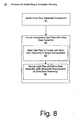
- Figure 8 is a flowchart of the steps in an exemplary method for assembling a computer housing, according to an embodiment of the present invention.
- A computer housing, removable light pipe device, and method for assembling a computer are disclosed. Reference is now made in detail to several embodiments of the invention, examples of which are illustrated in the accompanying drawing figures. While the invention will be described in conjunction with these embodiments, it will be understood that they are not intended to limit the invention to these embodiments. On the contrary, the invention is intended to cover alternatives, modifications and equivalents, which may be included within the spirit and scope of the invention as defined by the appended claims.
- Furthermore, in the following detailed description of the present invention, numerous specific details are set forth in order to provide a thorough understanding of the present invention. However, one of ordinary skill in the art will realize that embodiments of the present invention may be practiced without these specific details. In other instances, well-known devices, circuits, methods, processes, procedures, systems, components, and apparatus, etc. have not been described in detail so as not to unnecessarily obscure aspects of the present invention.
- A portion of the detailed description that follows is presented and discussed in terms of a process. Although steps and sequencing thereof are disclosed in a figure herein (e.g., Figure 8) describing the operations of this process (e.g., process 80), such steps and sequencing are exemplary. Embodiments of the present invention are well suited to performing various other steps or variations of the steps recited in the flowchart of the figure herein, and in a sequence other than that depicted and described herein.
- Embodiments of the present invention provide a computer housing, removable light pipe device, and method for assembling a computer. In one embodiment, the computer housing has a drive door assembly and a light pipe. The light pipe is removably coupleable with the drive door assembly. In one embodiment, in a coupled aspect, a structural characteristic of the drive door assembly secures the light pipe therewith. In one embodiment, the light pipe is labeled for one installation. In one embodiment, the light pipe is configured for one installation configuration.
- Therefore, embodiments of the present invention allow a light pipe to be removed, decoupled, etc. from a computer housing without damage to the light pipe or to another component of the computer housing. Confusion, mis-selection, incorrect configuration, and mis-installation of a light pipe, are deterred with light pipes and computer housings according to embodiments of the present invention. Further, in the event of incorrect configuration and/or mis-installation of a light pipe according to an embodiment of the present invention, the mis-installed or mis-configured light pipe can be readily removed and replaced without damaging the light pipe and/or another component of the computer housing.
- Figure 1 depicts an
exemplary computer housing 10, according to an embodiment of the present invention, from an outer perspective.Computer housing 10 has afront panel 11.Front panel 11 couples with acase 16 and functions as a protective front surface forcomputer housing 11, which allows users to access and interface with components internal to thecomputer housing 11, such as drives. - For instance,
front panel 11 has adrive door assembly 18 for accessing and interfacing with an internal drive (e.g., drive 22; Fig. 2). Drivedoor assembly 18 has adrive door 12 for accessing an internal drive, aneject actuator 14 for interfacing with the internal drive to causedrive door 12 to operate, and anindicator 15 for displaying a visual indication relating to the operation of the internal drive. Drivedoor assembly 18 can be a component of, integral with, etc.front panel 11. - It is appreciated that embodiments of the present invention may be practiced with functionality, exemplified herein with reference to
front panel 11, wherein the computer housing is configured, oriented, etc. in such a way that the functionality is oriented to an aspect (e.g., direction, position, orientation, etc.) other than the front of the computer housing. It is further appreciated that the computer housing exemplified herein with reference tocomputer housing 10 can have any shape, size, configuration, orientation, etc., and can house any kind of computer, instrument, electronic apparatus, etc. - Figure 2 depicts
exemplary computer housing 10, according to an embodiment of the present invention, from an exploded perspective.Case 16 andfront panel 11 couple and are structurally supported with asturdy frame 21.Frame 21 supports, mounts, etc. one or more drives 22 (e.g., and other components). -
Drive 22 is a drive for an optical medium such as a compact disk (CD), a digital versatile disk (DVD) with which data and program storage and/or retrieval such as reading, writing, and read/write operations, etc. can be performed.Drive 22 has a light emitting diode (LED) 25, which illuminates to indicate an operation thereof. For instance,LED 25 can illuminate responsive to drive 22 performing a read or a write operation, etc. -
Drive 22 also has aneject button 24, which when actuated, causes the drive to eject (e.g., or accept) media, such as a CD, DVD, etc. Withfront panel 11 in place withcase 16, drive door assembly is positioned proximate to drive 22 such that ejectactuator 14 actuates ejectbutton 24 responsive to a user action. - With
front panel 11 in place withcase 16, drivedoor assembly 18 is positioned proximate to drive 22 such thatindicator 15 provides indication responsive toLED 25 illuminating, which displays the indication provided byLED 25 outside ofcomputer housing 10, e.g., in front offront panel 11. Withfront panel 11 in place withcase 16, drivedoor assembly 18 is positioned proximate to drive 22 such thatindicator 15 is proximate to a position P ondrive 22, which is a distance D away fromLED 25. - Figure 3 depicts exemplary
front panel 11, according to an embodiment of the present invention, from a rear perspective. Theeject button 14 is belowdrive door 12 wherein, withfront panel 11 in place withcase 16, drivedoor assembly 18 is positioned such that the rear ofeject actuator 14 is proximate toejection button 24 sufficient to actuateeject button 14 responsive to a user action, e.g., pressing the front accessible side of eject actuator 14 (Fig. 1, 2). - Drive
door 12 has one ormore components 29 such as ramps, with which it can be operated with drive 22 (Fig. 2). Drivedoor 12 can also be spring actuated, spring assisted, etc. and/or can function with other mechanical components (e.g., ledges, levers, cams, gears, surfaces, etc.), with electromechanical components, etc. - Drive door assembly has a
light pipe 30 for transmitting light emitted by LED 25 (Fig. 2) to indicator 15 (Fig. 1, 2). Withfront panel 11 in place withcase 16, drivedoor assembly 18 is positioned such thatlight pipe 30 conducts light emitted byLED 25 at position P' to be displayed withindicator 15 at position P. From the perspective depicted, one end oflight pipe 30 coversindicator 15 at position P and its other end faces position P'.Light pipe 30 thus has a length corresponding to the distance D, e.g., the horizontal distance betweenLED 25 andindicator 15 with respect tofront panel 11. - Figure 4 depicts an exemplary removable
light pipe 30, according to an embodiment of the present invention.Light pipe 30 has anoptical conductor 40 with afirst end 41 and asecond end 42. Light entersoptical conductor 40 at anoptical entry portal 45, proximate to end 42.Optical conductor 40 is of a material, configuration, structure, etc. having optical qualities sufficient for coupling light entering atoptical entry port 45 to anoptical exit portal 46, which is proximate to end 41. In one embodiment,light pipe 30 has alabel 43 with which it is identified.Label 43 can be lased, inscribed, or etched into, affixed to, written on, etc. an outer surface ofoptical conductor 40, in any position and in such a way that it does not interfere with the optical conduction function thereof. - In one embodiment,
optical conductor 40 has a substantially cylindrical shape configuration wherein ends 41 and/or 42 have substantially circular, ellipsoidal, etc. contours. In one embodiment,optical conductor 40 comprises a transparent plastic, glass, or material of similar optical properties. - Figure 5 depicts an exemplary
light pipe installation 50, according to an embodiment of the present invention. Ininstallation 50,light pipe 30 couples with thedrive door assembly 18 wherein, in their coupled aspect, astructural characteristic 59 ofdoor assembly 15 securesoptical conductor 40 therewith. - One or more such
structural characteristics 59 can function to securelight pipe 30 withdoor assembly 15. The structural characteristic 59 can be a component part, an integral piece, etc. The structural characteristic 59 can securelight pipe 30 anddoor assembly 15 with plastic and/or elastic forces, structural conformity, mechanical coupling, etc. - Importantly, while the
structural characteristic 59 ofdrive door assembly 18 couples lightpipe 30 securely withdoor assembly 15,light pipe 30 anddoor assembly 15 are coupled such thatlight pipe 30 can be readily, e.g., easily, quickly, with little effort, and without damage to either, decoupled therefrom. - In one embodiment,
light pipe 30 has a key 57, which can be of integral construction withoptical conductor 40 and/or appurtenant thereto.Key 57 functions withoptical conductor 40 to couple theoptical conductor 40 with thedoor assembly 15 in a configuration whereinend 42 is coupled with a first location ondoor assembly 15, e.g., proximate to position P' conforming toLED 25, and whereinend 41 is coupled with a second location on the door assembly, e.g., proximate to position P conforming toindicator 14. -
Key 57 also functions to deter couplingoptical conductor 40 withdoor assembly 15 in another configuration. Advantageously, this can deter improper installation oflight pipe 30.Key 57 conforms with astructural feature 58, such as a recess, a lock mechanism, a detent, etc., ofdoor assembly 15.Structural feature 58 functions with key 57 to couplelight pipe 30 and thedoor assembly 15 in their proper configuration. - In one embodiment,
light pipe 30 comprises one of a plurality of different light pipes, each for example correspondingly labeled by a distinctive (e.g., different, individual, etc.) label 43 (Fig. 4) and each having adistinctive key 57. In this embodiment,structural feature 58 is correspondingly distinctive and functions with key 57 to couple only theproper light pipe 30 for aparticular door assembly 15, in their proper configuration. - With
front panel 11 in place with case 16 (Fig. 1, 2),light pipe 30 is configured wherein light fromLED 25 entersoptical conductor 40 atoptical entry portal 45.Optical conductor 40 couples the light entering atoptical entry portal 45 tooptical exit portal 46. The light exitsoptical conductor 40 atoptical exit portal 46 and is displayed as a luminous indication withindicator 14. - Figure 6 depicts an exemplary computer housing 60 with multiple
drive door assemblies front panel 69.Front panel 69 couples withcase 16 and functions as a protective front surface for computer housing 60, which allows users to access and interface with components such as drives, which are internal to the computer housing 60. Drivedoor assemblies front panel 69. - Drive
door assembly 61 accesses a first internal drive. Aneject actuator 64 interfaces with that internal drive to causedrive door 601 to operate.Indicator 65 displays a visual indication relating to the operation of that internal drive. - Drive
door assembly 62 accesses a second internal drive. Aneject actuator 66 interfaces with that internal drive to causedrive door 62 to operate.Indicator 67 displays a visual indication relating to the operation of that internal drive. - Figure 7 depicts exemplary
front panel 69, according to an embodiment of the present invention, from a rear perspective, e.g., looking at a rear surface thereof, which would face towards the inside ofcase 16 and drives therein. Theeject buttons drive doors front panel 69 in place withcase 16,drive door assemblies eject actuators eject actuators - Drive
doors more components 29 such as ramps, with which it can be operated with the drives. Drivedoors - Drive
door assemblies light pipes indicator 65 and 67 (Fig. 6).Light pipes - With
front panel 69 in place withcase 16,drive door assemblies light pipes indicator 15 at positions P. From the perspective depicted, one end oflight pipe 71 coversindicator 65 at position P and its other end faces a position P'.Light pipes front panel 69, between the LEDs of the internal devices andindicators indicators - Figure 8 is a flowchart of the steps in an
exemplary process 80 for assembling a computer housing, according to an embodiment of the present invention.Process 80 begins withstep 81, wherein a drive door assembly is installed into a component of the computer housing, such as a front or other panel. - In
step 82, a light pipe is removably coupled with the drive door assembly. The light pipe can be readily decoupled with the drive door assembly if desired, without damage to either component. In one embodiment, the light pipe is removably coupled with the drive door assembly comprisessteps 83 and 84. - In step 83, the light pipe is aligned to couple with the drive door assembly in a single configuration. For instance, coupling the light pipe with the drive door assembly in any other configuration is deterred, e.g., by one or more structural features of the light pipe and/or the drive door assembly.
- In
step 84, the light pipe is secured with the drive door assembly, such as with a structural characteristic of the drive door assembly, completingprocess 80. In one embodiment, one or more of the same or other structural characteristics align the light pipe to couple with the drive door assembly.
Claims (10)
- A computer housing (10), comprising:a drive door assembly (18); anda light pipe (30) coupled to said drive door assembly (18), wherein said light pipe (30) is removable.
- The computer housing (10) as recited in Claim 1 wherein said drive door (12) opens for access to a drive (22) comprising an optical drive.
- The computer housing (10) as recited in Claim 1 wherein said light pipe device (30) comprises:an optical conductor (40) with a first end (41) and a second end (42) wherein said optical conductor component (40) is configured for removable coupling with a door assembly (18) of said drive (22); anda key (57) functioning with said optical conductor (40) to couple said optical conductor (40) with said door assembly (18) in one configuration wherein said first end (41) is coupled with a first location on said door assembly (18), wherein said second end (42) is coupled with a second location on said door assembly (18), and wherein said key (57) further functions to deter coupling said optical conductor (40) with said door assembly (18) in another configuration.
- The computer housing (10) as recited in Claim 3 wherein said door assembly (18) comprises one (61) of a plurality of door assemblies (61, 62), wherein said light pipe device (40) is configured for removably coupling with said one door assembly (61), and wherein said key (57) further functions to deter coupling said optical conductor (40) with another door assembly (62) of said plurality of door assemblies.
- The computer housing (10) as recited in Claim 3 wherein said optical conductor (40) is integrated with said key (57).
- The computer housing (10) as recited in Claim 1 further comprising a label (43) for identifying said light pipe device (30).
- The computer housing (10) as recited in Claim 6 wherein said label (43) is integrated with said optical conductor (40).
- The computer housing (10) as recited in Claim 6 wherein said label (43) further identifies said drive door (18, 61).
- The computer housing (10) as recited in Claim 3 wherein said optical conductor (40) removably couples with said door assembly (18) wherein, in a coupled aspect, a structural characteristic (59) of said door assembly (18) secures said optical conductor (40) with said door assembly (18).
- A light pipe device (30) for an drive door (12), comprising:an optical conductor (40) with a first end (41) and a second end (42) wherein said optical conductor component (40) is configured for removable coupling with a door assembly (18) of said drive (12); anda key (57) functioning with said optical conductor (40) to couple said optical conductor (40) with said door assembly (18) in one configuration wherein said first end (41) is coupled with a first location on said door assembly (18), wherein said second end (42) is coupled with a second location on said door assembly (18), and wherein said key (57) further functions to deter coupling said optical conductor (30) with said door assembly (18) in another configuration.
Applications Claiming Priority (1)
| Application Number | Priority Date | Filing Date | Title |
|---|---|---|---|
| US10/970,138 US7215553B2 (en) | 2004-10-20 | 2004-10-20 | Computer housing with removable light pipe |
Publications (2)
| Publication Number | Publication Date |
|---|---|
| EP1650635A1 true EP1650635A1 (en) | 2006-04-26 |
| EP1650635B1 EP1650635B1 (en) | 2007-09-12 |
Family
ID=35464093
Family Applications (1)
| Application Number | Title | Priority Date | Filing Date |
|---|---|---|---|
| EP05256175A Expired - Fee Related EP1650635B1 (en) | 2004-10-20 | 2005-10-03 | Computer housing with removable light pipe |
Country Status (4)
| Country | Link |
|---|---|
| US (1) | US7215553B2 (en) |
| EP (1) | EP1650635B1 (en) |
| CN (1) | CN1763692B (en) |
| DE (1) | DE602005002435T2 (en) |
Families Citing this family (2)
| Publication number | Priority date | Publication date | Assignee | Title |
|---|---|---|---|---|
| US20130019045A1 (en) * | 2011-07-14 | 2013-01-17 | International Business Machines Corporation | Consolidating Computer Memory Drive Management In A Computing System |
| JP7177803B2 (en) * | 2020-07-08 | 2022-11-24 | シャープ株式会社 | Display device |
Citations (3)
| Publication number | Priority date | Publication date | Assignee | Title |
|---|---|---|---|---|
| EP0426330A2 (en) * | 1989-10-27 | 1991-05-08 | International Business Machines Corporation | Enclosure for a computer |
| US5654873A (en) * | 1996-01-29 | 1997-08-05 | Silicon Graphics, Inc. | Single connector attachment drive sled assembly having light pipe coupled to a rail |
| US5721669A (en) * | 1995-09-15 | 1998-02-24 | Apple Computer, Inc. | Gear-driven docking apparatus for removable mass-storage drives |
Family Cites Families (10)
| Publication number | Priority date | Publication date | Assignee | Title |
|---|---|---|---|---|
| US6640235B1 (en) * | 1992-08-20 | 2003-10-28 | Intel Corporation | Expandable mass disk drive storage system |
| US5646816A (en) * | 1994-03-18 | 1997-07-08 | Lucent Technologies Inc. | Identification icon indicia for plug-in units of a power distribution system |
| US5684671A (en) * | 1995-08-22 | 1997-11-04 | Sequent Computer Systems, Inc. | Packaging architecture for a data server |
| US5938324A (en) * | 1996-10-07 | 1999-08-17 | Cisco Technology, Inc. | Light pipe |
| US6428216B1 (en) * | 1998-11-09 | 2002-08-06 | John M. Savage, Jr. | Optical coupling of light pipes, with light diffusion |
| US6483107B1 (en) * | 1999-05-11 | 2002-11-19 | Josef Rabinovitz | Canister having a combined guide rail and light pipe system for use in a computer peripheral enclosure |
| US6231224B1 (en) * | 1999-09-22 | 2001-05-15 | International Business Machines Corporation | Light pipe guide and carrier for hard disk drive |
| US20020036699A1 (en) * | 2000-09-15 | 2002-03-28 | Nicklos Carl F. | Light pipe having an improved mounting structure and method of assembling same |
| US6747874B2 (en) * | 2002-11-12 | 2004-06-08 | Dell Products L.P. | Rack system with rear status indicator and method of use |
| US7145776B2 (en) * | 2003-12-22 | 2006-12-05 | Emc Corporation | Midplane-less data storage enclosure |
-
2004
- 2004-10-20 US US10/970,138 patent/US7215553B2/en not_active Expired - Fee Related
-
2005
- 2005-10-03 EP EP05256175A patent/EP1650635B1/en not_active Expired - Fee Related
- 2005-10-03 DE DE602005002435T patent/DE602005002435T2/en active Active
- 2005-10-19 CN CN2005101164762A patent/CN1763692B/en not_active Expired - Fee Related
Patent Citations (3)
| Publication number | Priority date | Publication date | Assignee | Title |
|---|---|---|---|---|
| EP0426330A2 (en) * | 1989-10-27 | 1991-05-08 | International Business Machines Corporation | Enclosure for a computer |
| US5721669A (en) * | 1995-09-15 | 1998-02-24 | Apple Computer, Inc. | Gear-driven docking apparatus for removable mass-storage drives |
| US5654873A (en) * | 1996-01-29 | 1997-08-05 | Silicon Graphics, Inc. | Single connector attachment drive sled assembly having light pipe coupled to a rail |
Also Published As
| Publication number | Publication date |
|---|---|
| CN1763692A (en) | 2006-04-26 |
| US7215553B2 (en) | 2007-05-08 |
| CN1763692B (en) | 2012-03-21 |
| US20060083018A1 (en) | 2006-04-20 |
| EP1650635B1 (en) | 2007-09-12 |
| DE602005002435D1 (en) | 2007-10-25 |
| DE602005002435T2 (en) | 2008-09-18 |
Similar Documents
| Publication | Publication Date | Title |
|---|---|---|
| CN2837924Y (en) | Encrypted removable storage system | |
| JP3605048B2 (en) | Device holding device and chassis for information processing system having the same | |
| CN102013262B (en) | Information processing device | |
| US5816672A (en) | Three-position locking mechanism | |
| US6157532A (en) | Computer system access panel having a biased cover latching mechanism | |
| TWI492125B (en) | Track pad acoustic features related to a portable computer | |
| JP4845979B2 (en) | Information processing device | |
| JP3982941B2 (en) | Storage device | |
| US20010015885A1 (en) | Electric apparatus with cover for opening/closing receptacle containing module | |
| US6560097B2 (en) | Electronic apparatus | |
| US20110035519A1 (en) | Computer storage device adapter | |
| EP1650635B1 (en) | Computer housing with removable light pipe | |
| US7035095B2 (en) | Computer system and chassis | |
| US7113398B2 (en) | Removable storage device unit | |
| US20140269240A1 (en) | Drive carrier substrate | |
| US4636781A (en) | Housing for data terminal device | |
| JP2005070969A (en) | Electronic equipment, and operation unit used for electronic equipment | |
| US8437132B2 (en) | Computer enclosure with cover plate | |
| US6847367B1 (en) | Display for port area of electronic equipment | |
| US6271985B1 (en) | Flanged cover for a low profile magnetic disk apparatus | |
| KR100460766B1 (en) | Detaching device of a test device for a hard disk drive, specifically related to realizing a detaching function by alternately locking and unlocking with a locking pin | |
| EP1517321A1 (en) | Inventory control device | |
| JP4488442B2 (en) | Game machine | |
| KR101520500B1 (en) | computer memory storage | |
| US7277278B2 (en) | Hinged panel and disc drive for a computer |
Legal Events
| Date | Code | Title | Description |
|---|---|---|---|
| PUAI | Public reference made under article 153(3) epc to a published international application that has entered the european phase |
Free format text: ORIGINAL CODE: 0009012 |
|
| AK | Designated contracting states |
Kind code of ref document: A1 Designated state(s): AT BE BG CH CY CZ DE DK EE ES FI FR GB GR HU IE IS IT LI LT LU LV MC NL PL PT RO SE SI SK TR |
|
| AX | Request for extension of the european patent |
Extension state: AL BA HR MK YU |
|
| 17P | Request for examination filed |
Effective date: 20060807 |
|
| 17Q | First examination report despatched |
Effective date: 20060901 |
|
| AKX | Designation fees paid |
Designated state(s): DE FR GB |
|
| GRAP | Despatch of communication of intention to grant a patent |
Free format text: ORIGINAL CODE: EPIDOSNIGR1 |
|
| GRAS | Grant fee paid |
Free format text: ORIGINAL CODE: EPIDOSNIGR3 |
|
| GRAA | (expected) grant |
Free format text: ORIGINAL CODE: 0009210 |
|
| AK | Designated contracting states |
Kind code of ref document: B1 Designated state(s): DE FR GB |
|
| REG | Reference to a national code |
Ref country code: GB Ref legal event code: FG4D |
|
| REF | Corresponds to: |
Ref document number: 602005002435 Country of ref document: DE Date of ref document: 20071025 Kind code of ref document: P |
|
| ET | Fr: translation filed | ||
| PLBE | No opposition filed within time limit |
Free format text: ORIGINAL CODE: 0009261 |
|
| STAA | Information on the status of an ep patent application or granted ep patent |
Free format text: STATUS: NO OPPOSITION FILED WITHIN TIME LIMIT |
|
| 26N | No opposition filed |
Effective date: 20080613 |
|
| PGFP | Annual fee paid to national office [announced via postgrant information from national office to epo] |
Ref country code: GB Payment date: 20130923 Year of fee payment: 9 |
|
| PGFP | Annual fee paid to national office [announced via postgrant information from national office to epo] |
Ref country code: DE Payment date: 20130920 Year of fee payment: 9 Ref country code: FR Payment date: 20131028 Year of fee payment: 9 |
|
| REG | Reference to a national code |
Ref country code: DE Ref legal event code: R119 Ref document number: 602005002435 Country of ref document: DE |
|
| GBPC | Gb: european patent ceased through non-payment of renewal fee |
Effective date: 20141003 |
|
| PG25 | Lapsed in a contracting state [announced via postgrant information from national office to epo] |
Ref country code: DE Free format text: LAPSE BECAUSE OF NON-PAYMENT OF DUE FEES Effective date: 20150501 Ref country code: GB Free format text: LAPSE BECAUSE OF NON-PAYMENT OF DUE FEES Effective date: 20141003 |
|
| REG | Reference to a national code |
Ref country code: FR Ref legal event code: ST Effective date: 20150630 |
|
| PG25 | Lapsed in a contracting state [announced via postgrant information from national office to epo] |
Ref country code: FR Free format text: LAPSE BECAUSE OF NON-PAYMENT OF DUE FEES Effective date: 20141031 |