EP1645918A1 - Anti-tripping device for timepiece escapement - Google Patents
Anti-tripping device for timepiece escapement Download PDFInfo
- Publication number
- EP1645918A1 EP1645918A1 EP04023667A EP04023667A EP1645918A1 EP 1645918 A1 EP1645918 A1 EP 1645918A1 EP 04023667 A EP04023667 A EP 04023667A EP 04023667 A EP04023667 A EP 04023667A EP 1645918 A1 EP1645918 A1 EP 1645918A1
- Authority
- EP
- European Patent Office
- Prior art keywords
- balance
- columns
- finger
- bridge
- clamp
- Prior art date
- Legal status (The legal status is an assumption and is not a legal conclusion. Google has not performed a legal analysis and makes no representation as to the accuracy of the status listed.)
- Withdrawn
Links
Images


Classifications
-
- G—PHYSICS
- G04—HOROLOGY
- G04B—MECHANICALLY-DRIVEN CLOCKS OR WATCHES; MECHANICAL PARTS OF CLOCKS OR WATCHES IN GENERAL; TIME PIECES USING THE POSITION OF THE SUN, MOON OR STARS
- G04B43/00—Protecting clockworks by shields or other means against external influences, e.g. magnetic fields
- G04B43/002—Component shock protection arrangements
Definitions
- the present invention relates to an anti-gallop device for a clock escapement, this escapement comprising, inter alia, a spiral composed of several turns and a rocker provided with at least one arm, the rocker being pivotally mounted between a plate and a bridge, said device comprising a finger fixed on the arm of the balance, two columns between which can pass the finger when the pendulum is in motion, these columns being integral with the bridge of said balance, and a locking arm fixed on the outer turn of the spiral, this locking arm being capable of being interposed between said columns and said finger to prevent the rotation of the balance beyond an angle exceeding its normal operating angle.
- This device is implemented in so-called expansion escapements that are suitable for large timepieces such as marine chronometers. These parts are appreciated for their great precision, which is why it is very often called a relaxation exhaust itself renowned for its high accuracy.
- This exhaust has an important defect, namely its sensitivity to shocks. Because of this, it is considered not to be well suited to wristwatches. Indeed a shock applied to the timepiece can cause the pendulum to rotate beyond a normal operating angle. It then occurs a gallop because two clearances and two pulses occur during the same alternation.
- the present invention besides it obeys the generic definition in the first paragraph of this description, is remarkable in that the locking arm is a clamp attached to the outer coil of the spiral.
- FIGS. 1 and 2 show only the elements necessary for the understanding of the invention namely a spiral 1 composed of several turns 9 and 10 and a rocker 2 provided with at least one arm 3 and pivotally mounted between a plate (not shown) and a bridge 4.
- the detent escapement further comprises the following elements not shown in the drawings, namely: an escape wheel provided with generally pointed teeth which rest in turn on a pallet of rest, a rocker blocker recalled by a spring, this blocker carrying at its first end said pallet rest and at its second end a first actuating finger capable of being actuated by a second actuating finger carried by a plate integral with the balance, this plate also carrying a pallet of pulses adapted to receive pulses from the teeth of the escape wheel.
- the rest pallet is disengaged from the tooth of the escape wheel and one and other teeth of the same wheel, acting on the impulse pallet gives a pulse to the pendulum.
- the second actuating finger is arranged so as to actuate the first finger of the blocker only in a direction of rotation of the balance, that is to say during the first alternation of the oscillation then what takes place the impulse.
- the first finger of the blocker is not actuated because the second finger carried by the plate is arranged for s' then hide from what no impulse occurs.
- the anti-gallop device proposed in the work cited above and illustrated in Figures 1 and 2 of the present invention comprises a finger 5 fixed on the arm of the balance 2 and two columns 6 and 7 between which can pass the finger when the pendulum is moving, these columns being secured to the bridge 4 of the pendulum.
- the device also comprises a locking arm 8 fixed on the outer turn 10 of the hairspring 1. As shown particularly in FIG. 2, this locking arm 8 comes to interpose between the columns 6 and 7 and the finger 5 to prevent the rotation of the balance 2 beyond an angle exceeding its normal angle of rotation.
- the present invention is remarkable in that the locking arm 8 is a clamp attached to the outer turn 10 of the hairspring 1.
- This method is perfectly adapted to small spirals that we meet in wristwatches for example.
- the system envisaged does not require any complicated preparation and machining of the locking arm as is the case of the arm in the cited work.
- the clamp can be placed on the outer turn without difficulty, at the desired location, without the need to put on the spiral and fix it on the latter as provided in the same book.
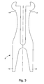
- the clamp 8 can be in various forms including that which is illustrated in Figures 2 and 3.
- the clamp has the shape of an X whose upper branches 11 and 12 are shaped to hug the spiral.
- Figure 3 shows particularly that the upper branches are cut in the form of beveled jaws to tighten well on the spiral.
- the lower branches 13 and 14 are arranged to serve as means for gripping and placing the clamp.
- a tool specially designed for this gripping and positioning will allow gripping the gripper by its branches 13 and 14 and then bringing them together to elastically separate the upper branches 11 and 12 to install them on the hairspring. It will be understood that this clamp 8 can be made from a blade by simple stamping or chemical etching.
- the two columns 6 and 7 integral with the bridge 4 could consist of two pins driven in this bridge.
- the present invention however provides for simplifying this passage by proposing, as shown in Figures 1 and 2, a gantry 15 whose two columns 6 and 7 are connected by a cross member 16, this cross member carrying a rod 17 driven into the bridge 4 of the pendulum 2.
Abstract
Description
La présente invention est relative à un dispositif anti-galop pour un échappement d'horlogerie, cet échappement comprenant entre autres un spiral composé de plusieurs spires et un balancier pourvu d'au moins un bras, le balancier étant monté à pivotement entre une platine et un pont, ledit dispositif comprenant un doigt fixé sur le bras du balancier, deux colonnes entre lesquelles peut passer le doigt quand le balancier est en mouvement, ces colonnes étant solidaires du pont dudit balancier, et un bras de blocage fixé sur la spire extérieure du spiral, ce bras de blocage étant susceptible de s'interposer entre lesdites colonnes et ledit doigt pour empêcher la rotation du balancier au-delà d'un angle dépassant son angle de fonctionnement normal.The present invention relates to an anti-gallop device for a clock escapement, this escapement comprising, inter alia, a spiral composed of several turns and a rocker provided with at least one arm, the rocker being pivotally mounted between a plate and a bridge, said device comprising a finger fixed on the arm of the balance, two columns between which can pass the finger when the pendulum is in motion, these columns being integral with the bridge of said balance, and a locking arm fixed on the outer turn of the spiral, this locking arm being capable of being interposed between said columns and said finger to prevent the rotation of the balance beyond an angle exceeding its normal operating angle.
Un tel dispositif est connu. Il a été décrit dans l'ouvrage intitulé "Der Chronometer Gang" dû au professeur Alois Irk et publié par Deutsche Uhrmacher Zeitung, Berlin 1923. On se référera particulièrement aux paragraphes 116 à 120 (pages 74 à 77) et à la figure 25 de l'ouvrage cité.Such a device is known. It has been described in the book "Der Chronometer Gang" by Professor Alois Irk and published by Deutsche Uhrmacher Zeitung, Berlin, 1923. Particular reference is made to paragraphs 116 to 120 (pages 74 to 77) and figure 25 of the work cited.
Ce dispositif est mis en oeuvre dans les échappements dits à détente qui conviennent à des pièces d'horlogerie de grande dimension comme des chronomètres de marine. Ces pièces sont appréciées pour leur grande précision, raison pour laquelle il est fait appel très souvent à un échappement à détente lui-même réputé pour sa grande précision. Cet échappement cependant présente un défaut important, à savoir sa sensibilité aux chocs. De ce fait, il est réputé ne pas bien convenir aux montres-bracelet. En effet un choc appliqué à la pièce d'horlogerie peut amener son balancier à tourner au-delà d'un angle normal de fonctionnement. Il se produit alors un galop car deux dégagements et deux impulsions ont lieu pendant la même alternance.This device is implemented in so-called expansion escapements that are suitable for large timepieces such as marine chronometers. These parts are appreciated for their great precision, which is why it is very often called a relaxation exhaust itself renowned for its high accuracy. This exhaust, however, has an important defect, namely its sensitivity to shocks. Because of this, it is considered not to be well suited to wristwatches. Indeed a shock applied to the timepiece can cause the pendulum to rotate beyond a normal operating angle. It then occurs a gallop because two clearances and two pulses occur during the same alternation.
Lorsque l'on désire équiper une pièce d'horlogerie de petite dimension, par exemple une montre-bracelet, d'un échappement à détente pour remplacer par exemple l'échappement à ancre classique et la faire bénéficier ainsi des avantages conférés par cet échappement, il s'agira d'utiliser de nouvelles techniques différentes de celles connues jusqu'à aujourd'hui si l'on ne veut pas aboutir à un échec. Diverses solutions ont été proposées récemment pour pallier le manque d'énergie développée par le balancier-spiral d'une montre-bracelet pour vaincre les forces agissant sur la détente d'un échappement à détente. Il n'en reste pas moins que le problème du galop demeure et qu'il s'agit de le résoudre lorsqu'on a affaire à un spiral de petite dimension, tel celui monté sur une montre-bracelet.When it is desired to equip a small timepiece, for example a wristwatch, with a detent escapement to replace for example the classic anchor escapement and thus benefit from the advantages conferred by this escapement, it will be using new techniques different from those known until today if we do not want to lead to failure. Various solutions have been proposed recently to overcome the lack of energy developed by the sprung balance of a wristwatch to overcome the forces acting on the trigger of a detent escapement. Nevertheless, the problem of galloping remains and it is to solve it when dealing with a small spiral, such as the one mounted on a wristwatch.
Si l'on se réfère à l'ouvrage cité ci-dessus, on s'aperçoit que le bras de blocage proposé pour le dispositif anti-galop convient exclusivement à un spiral de grande dimension. Il s'agit en fait d'une pièce ayant subi plusieurs usinages dont un perçage à travers lequel va passer la dernière spire du spiral. Une telle façon de faire convient mal à un spiral de petite dimension, de plus son exécution est lourde et compliquée.If one refers to the work cited above, one realizes that the proposed locking arm for the anti-gallop device is suitable only for a large spiral. It is actually a piece that has undergone several machining including a hole through which will pass the last turn of the spiral. Such a way of doing is not well suited to a small spiral, moreover its execution is heavy and complicated.
Pour pallier les inconvénients cités, la présente invention, outre qu'elle obéit à la définition générique posée au premier paragraphe de cette description, est remarquable en ce que le bras de blocage est une pince accrochée sur la spire extérieure du spiral.To overcome the disadvantages mentioned, the present invention, besides it obeys the generic definition in the first paragraph of this description, is remarkable in that the locking arm is a clamp attached to the outer coil of the spiral.
Les caractéristiques et avantages de la présente invention ressortiront de la description qui va suivre, faite en regard des dessins annexés, et donnant à titre d'exemple explicatif, mais nullement limitatif, une forme avantageuse de la réalisation d'un dispositif anti-galop pour une montre-bracelet équipée d'un échappement à détente, dessins dans lesquels :
- la figure 1 est une vue en perspective du dispositif anti-galop montrant le bras de blocage selon l'invention,
- la figure 2 est une vue de profil montrant en conjonction les divers éléments entrant en jeu pour empêcher le galop de l'échappement, et
- la figure 3 est une vue en plan de la pince utilisée comme bras de blocage selon l'invention.
- FIG. 1 is a perspective view of the anti-gallop device showing the locking arm according to the invention,
- Figure 2 is a side view showing in conjunction the various elements involved to prevent the gallop of the exhaust, and
- Figure 3 is a plan view of the clamp used as locking arm according to the invention.
On va décrire maintenant le dispositif anti-galop en se référant aux figures 1 et 2. Ce dispositif est destiné à un échappement d'horlogerie, plus particulièrement à un échappement à détente dont ne sont représentés aux figures 1 et 2 que les éléments nécessaires à la compréhension de l'invention à savoir un spiral 1 composé de plusieurs spires 9 et 10 et un balancier 2 pourvu d'au moins un bras 3 et monté à pivotement entre une platine (non représentée) et un pont 4.The anti-gallop device will now be described with reference to FIGS. 1 and 2. This device is intended for a watch exhaust, more particularly for a trigger escapement of which FIGS. 1 and 2 show only the elements necessary for the understanding of the invention namely a spiral 1 composed of
L'échappement à détente comporte en outre les éléments suivants non représentés aux dessins, à savoir : une roue d'échappement munie de dents généralement pointues qui reposent à tour de rôle sur une palette de repos, un bloqueur à bascule rappelé par un ressort, ce bloqueur portant à sa première extrémité ladite palette de repos et à sa seconde extrémité un premier doigt d'actionnement susceptible d'être actionné par un second doigt d'actionnement porté par un plateau solidaire du balancier, ce plateau portant en outre une palette d'impulsions apte à recevoir des impulsions en provenance des dents de la roue d'échappement. A chaque oscillation du balancier, la palette de repos est dégagée de la dent de la roue d'échappement et une et autre dent de la même roue, agissant sur la palette d'impulsion, donne une impulsion au balancier. On observera que le second doigt d'actionnement est arrangé de façon à n'actionner le premier doigt du bloqueur que dans un sens de rotation du balancier, c'est-à-dire lors de la première alternance de l'oscillation ensuite de quoi a lieu l'impulsion. Quand le balancier tourne dans l'autre sens, c'est-à-dire lors de la seconde alternance de l'oscillation, le premier doigt du bloqueur n'est pas actionné car le second doigt porté par le plateau est arrangé pour s'escamoter ensuite de quoi aucune impulsion ne se produit. Les explications qui viennent d'être données font comprendre que si la première alternance amène le balancier à tourner au-delà d'une amplitude normale qui est de l'ordre de 320 degrés, par exemple à la suite d'un choc appliqué à la montre, le premier doigt du bloqueur peut être actionné une seconde fois. Il se produit alors une seconde impulsion pendant la même alternance, ce qui entraîne l'échappement à galoper.The detent escapement further comprises the following elements not shown in the drawings, namely: an escape wheel provided with generally pointed teeth which rest in turn on a pallet of rest, a rocker blocker recalled by a spring, this blocker carrying at its first end said pallet rest and at its second end a first actuating finger capable of being actuated by a second actuating finger carried by a plate integral with the balance, this plate also carrying a pallet of pulses adapted to receive pulses from the teeth of the escape wheel. At each oscillation of the balance wheel, the rest pallet is disengaged from the tooth of the escape wheel and one and other teeth of the same wheel, acting on the impulse pallet gives a pulse to the pendulum. It will be observed that the second actuating finger is arranged so as to actuate the first finger of the blocker only in a direction of rotation of the balance, that is to say during the first alternation of the oscillation then what takes place the impulse. When the rocker rotates in the other direction, that is to say during the second alternation of the oscillation, the first finger of the blocker is not actuated because the second finger carried by the plate is arranged for s' then hide from what no impulse occurs. The explanations that have just been given make it clear that if the first alternation causes the balance to rotate beyond a normal amplitude which is of the order of 320 degrees, for example following a shock applied to the shows, the first finger of the blocker can be operated a second time. There is then a second pulse during the same alternation, which causes the escapement to gallop.
Pour éviter ce phénomène, le dispositif anti-galop proposé dans l'ouvrage cité plus haut et illustré sur les figures 1 et 2 de la présente invention, comprend un doigt 5 fixé sur le bras du balancier 2 et deux colonnes 6 et 7 entre lesquelles peut passer le doigt quand le balancier est en mouvement, ces colonnes étant solidaires du pont 4 du balancier. Le dispositif comprend encore un bras de blocage 8 fixé sur la spire extérieure 10 du spiral 1. Comme le montre particulièrement bien la figure 2, ce bras de blocage 8 vient s'interposer entre les colonnes 6 et 7 et le doigt 5 pour empêcher la rotation du balancier 2 au-delà d'un angle dépassant son angle normal de rotation. En effet, à la fin de la première alternance, situation représentée en figure 1, le spiral 1 ainsi que sa dernière spire 10 présentent leurs plus grandes expansions ce qui conduit le bras de blocage 8 fixé sur cette dernière spire, à venir se placer entre le doigt 5 du bras 3 et les deux colonnes 6 et 7 du pont 4. A ce moment, si un choc est appliqué à la pièce d'horlogerie et si ce choc entraîne le balancier à poursuivre sa rotation dans le sens anti-horaire (flèche A), le doigt 5 vient buter contre le bras de blocage 8, ce dernier venant à son tour buter contre les colonnes 6 et 7 (situation illustrée en figure 2). Le balancier 2 est alors stoppé empêchant la seconde impulsion dont il a été question plus haut. Le galop est ainsi évité. On notera qu'à partir de ce moment le balancier va tourner dans le sens inverse pour parcourir sa seconde alternance. Le spiral 1 va se resserrer ainsi que la dernière spire 10 attirant le bras de blocage 8 vers le centre. Le bras de blocage 8 ne sera dès lors plus un obstacle au passage du doigt 5 entre les colonnes 6 et 7 qu'il franchira deux fois par oscillation.To avoid this phenomenon, the anti-gallop device proposed in the work cited above and illustrated in Figures 1 and 2 of the present invention comprises a
Comme le montrent les figures 1 à 3, la présente invention est remarquable en ce que le bras de blocage 8 est une pince accrochée sur la spire extérieure 10 du spiral 1. Cette façon de faire est parfaitement adaptée à des spiraux de petite dimension qu'on rencontre dans les montres-bracelet par exemple. Le système envisagé ne nécessite aucune préparation et usinage compliqués du bras de blocage comme c'est le cas du bras dans l'ouvrage cité. La pince peut être disposée sur la spire extérieure sans difficulté, à l'endroit voulu, sans qu'il soit nécessaire de l'enfiler sur le spiral et de la fixer sur ce dernier comme prévu dans le même ouvrage.As shown in FIGS. 1 to 3, the present invention is remarkable in that the
La pince 8 peut se présenter sous différentes formes dont celle qui est illustrée sur les figures 2 et 3. Ici la pince présente la forme d'un X dont les branches supérieures 11 et 12 sont conformées pour étreindre le spiral. La figure 3 montre particulièrement que les branches supérieures sont découpées en forme de mâchoires taillées en biseau permettant de bien serrer sur le spiral. Les branches inférieures 13 et 14 sont arrangées pour servir de moyens de préhension et de mise en place de la pince. Un outil spécialement conçu pour cette préhension et cette mise en place permettra de saisir la pince par ses branches 13 et 14 puis de les rapprocher afin d'écarter élastiquement les branches supérieures 11 et 12 pour les installer sur le spiral. On comprendra que cette pince 8 pourra être réalisée à partir d'une lame par simple étampage ou par gravage chimique.The
On notera enfin que les deux colonnes 6 et 7 solidaires du pont 4 pourraient consister en deux goupilles chassées dans ce pont. La présente invention prévoit cependant de simplifier ce passage en proposant, comme le montrent les figures 1 et 2, un portique 15 dont les deux colonnes 6 et 7 sont reliées par une traverse 16, cette traverse portant une tige 17 chassée dans le pont 4 du balancier 2.Note finally that the two
Claims (4)
Priority Applications (8)
| Application Number | Priority Date | Filing Date | Title |
|---|---|---|---|
| EP04023667A EP1645918A1 (en) | 2004-10-05 | 2004-10-05 | Anti-tripping device for timepiece escapement |
| EP20050020554 EP1666990B1 (en) | 2004-10-05 | 2005-09-21 | Anti-tripping device for timepiece escapement |
| AT05020554T ATE539387T1 (en) | 2004-10-05 | 2005-09-21 | DEVICE FOR CATERING PROTECTION FOR WATCH ESCULATION |
| SG200506172A SG121950A1 (en) | 2004-10-05 | 2005-09-27 | Antitripping device for watch-escapement |
| JP2005283471A JP4608632B2 (en) | 2004-10-05 | 2005-09-29 | Trip prevention device for watch escapement |
| US11/240,366 US7070321B2 (en) | 2004-10-05 | 2005-10-03 | Antitripping device for watch-escapement |
| CNB2005101082673A CN100462872C (en) | 2004-10-05 | 2005-10-08 | Antitripping device for watch-escapement |
| HK06105569.4A HK1085546A1 (en) | 2004-10-05 | 2006-05-15 | Antitripping device for watch-escapement |
Applications Claiming Priority (1)
| Application Number | Priority Date | Filing Date | Title |
|---|---|---|---|
| EP04023667A EP1645918A1 (en) | 2004-10-05 | 2004-10-05 | Anti-tripping device for timepiece escapement |
Publications (1)
| Publication Number | Publication Date |
|---|---|
| EP1645918A1 true EP1645918A1 (en) | 2006-04-12 |
Family
ID=34926844
Family Applications (1)
| Application Number | Title | Priority Date | Filing Date |
|---|---|---|---|
| EP04023667A Withdrawn EP1645918A1 (en) | 2004-10-05 | 2004-10-05 | Anti-tripping device for timepiece escapement |
Country Status (7)
| Country | Link |
|---|---|
| US (1) | US7070321B2 (en) |
| EP (1) | EP1645918A1 (en) |
| JP (1) | JP4608632B2 (en) |
| CN (1) | CN100462872C (en) |
| AT (1) | ATE539387T1 (en) |
| HK (1) | HK1085546A1 (en) |
| SG (1) | SG121950A1 (en) |
Cited By (4)
| Publication number | Priority date | Publication date | Assignee | Title |
|---|---|---|---|---|
| EP2434353A1 (en) | 2010-09-28 | 2012-03-28 | Montres Breguet SA | Anti-tripping hairspring for timepiece escapement |
| EP2450756A1 (en) | 2010-11-04 | 2012-05-09 | Nivarox-FAR S.A. | Anti-tripping device for escapement mechanism |
| EP2450757A1 (en) | 2010-11-04 | 2012-05-09 | Nivarox-FAR S.A. | Anti-tripping device for escapement mechanism |
| CN103576527A (en) * | 2012-07-25 | 2014-02-12 | 尼瓦洛克斯-法尔股份有限公司 | Anti-trip balance spring for timepiece |
Families Citing this family (3)
| Publication number | Priority date | Publication date | Assignee | Title |
|---|---|---|---|---|
| JP5953628B2 (en) * | 2012-02-17 | 2016-07-20 | セイコーインスツル株式会社 | Escapement machine and mechanical watch |
| CH707815B1 (en) | 2013-03-19 | 2017-05-31 | Nivarox Far Sa | Subassembly of a clockwork escapement mechanism comprising a spiral spring. |
| CN107250925B (en) * | 2014-01-13 | 2020-06-23 | 洛桑联邦理工学院 | Mechanical isotropic harmonic oscillator and oscillator system |
Citations (3)
| Publication number | Priority date | Publication date | Assignee | Title |
|---|---|---|---|---|
| US361850A (en) * | 1886-06-12 | 1887-04-26 | A Van Strait | Regulator pin for watches |
| AT225624B (en) * | 1961-04-04 | 1963-01-25 | Alfred Frick | Device for securing the spiral spring of balance clocks against jumping over |
| DE1206811B (en) * | 1962-04-11 | 1965-12-09 | Lars Aadnesen Loege | Safety device to prevent the Breguet hairspring from jumping over on balance watches |
Family Cites Families (11)
| Publication number | Priority date | Publication date | Assignee | Title |
|---|---|---|---|---|
| CH512094A (en) * | 1968-08-19 | 1971-04-30 | Lapanouse Montres Rego S A R | Racket key |
| CH516842A (en) * | 1968-08-30 | 1971-08-31 | Ism Equipements Ind De Montage | Method of assembling an assembly comprising the regulating members and the snowshoeing of a timepiece in the case where the hairspring is fixed to the pin by welding and equipment for its implementation |
| JPS5025188Y1 (en) * | 1970-12-28 | 1975-07-29 | ||
| JPS51301Y1 (en) * | 1973-05-09 | 1976-01-07 | ||
| DE2421750A1 (en) * | 1974-05-06 | 1975-11-20 | Timex Corp | IN PARTICULAR FOR ELECTRIC WATCHES, SPRING ARRANGEMENT |
| US3943701A (en) * | 1975-01-08 | 1976-03-16 | Timex Corporation | Regulator and balance bridge arrangement for a horological device |
| US3958410A (en) * | 1975-06-02 | 1976-05-25 | Timex Corporation | Termination device from hairspring-hub to drive coil on two conductor hairspring |
| JP3982290B2 (en) * | 1997-08-28 | 2007-09-26 | セイコーエプソン株式会社 | Spring, balance spring, and clock |
| CH692532A5 (en) * | 1997-10-21 | 2002-07-15 | Ebauchesfabrik Eta Ag | A method of making a balance spring for a horological movement. |
| EP1693722A3 (en) * | 1999-04-28 | 2007-10-31 | Seiko Instruments Inc. | Mechanical timepiece having a balance-with-hairspring rotation angle control mechanism |
| CN1324457A (en) * | 1999-06-29 | 2001-11-28 | 精工电子有限公司 | Mechanical time-piece with timed annular balance rotating angle control mechanism |
-
2004
- 2004-10-05 EP EP04023667A patent/EP1645918A1/en not_active Withdrawn
-
2005
- 2005-09-21 AT AT05020554T patent/ATE539387T1/en active
- 2005-09-27 SG SG200506172A patent/SG121950A1/en unknown
- 2005-09-29 JP JP2005283471A patent/JP4608632B2/en not_active Expired - Fee Related
- 2005-10-03 US US11/240,366 patent/US7070321B2/en active Active
- 2005-10-08 CN CNB2005101082673A patent/CN100462872C/en not_active Expired - Fee Related
-
2006
- 2006-05-15 HK HK06105569.4A patent/HK1085546A1/en not_active IP Right Cessation
Patent Citations (3)
| Publication number | Priority date | Publication date | Assignee | Title |
|---|---|---|---|---|
| US361850A (en) * | 1886-06-12 | 1887-04-26 | A Van Strait | Regulator pin for watches |
| AT225624B (en) * | 1961-04-04 | 1963-01-25 | Alfred Frick | Device for securing the spiral spring of balance clocks against jumping over |
| DE1206811B (en) * | 1962-04-11 | 1965-12-09 | Lars Aadnesen Loege | Safety device to prevent the Breguet hairspring from jumping over on balance watches |
Cited By (8)
| Publication number | Priority date | Publication date | Assignee | Title |
|---|---|---|---|---|
| EP2434353A1 (en) | 2010-09-28 | 2012-03-28 | Montres Breguet SA | Anti-tripping hairspring for timepiece escapement |
| US8764281B2 (en) | 2010-09-28 | 2014-07-01 | Montres Breguet Sa | Anti-trip balance-spring for a timepiece escapement |
| EP2450756A1 (en) | 2010-11-04 | 2012-05-09 | Nivarox-FAR S.A. | Anti-tripping device for escapement mechanism |
| EP2450757A1 (en) | 2010-11-04 | 2012-05-09 | Nivarox-FAR S.A. | Anti-tripping device for escapement mechanism |
| US8556499B2 (en) | 2010-11-04 | 2013-10-15 | Nivarox-Far S.A. | Anti-trip device for an escape mechanism |
| US8602637B2 (en) | 2010-11-04 | 2013-12-10 | Nivarox-Far S.A. | Anti-trip device for an escape mechanism |
| CN103576527A (en) * | 2012-07-25 | 2014-02-12 | 尼瓦洛克斯-法尔股份有限公司 | Anti-trip balance spring for timepiece |
| CN103576527B (en) * | 2012-07-25 | 2016-06-29 | 尼瓦洛克斯-法尔股份有限公司 | Anti-tripping hairspring for clock and watch |
Also Published As
| Publication number | Publication date |
|---|---|
| SG121950A1 (en) | 2006-05-26 |
| CN100462872C (en) | 2009-02-18 |
| JP4608632B2 (en) | 2011-01-12 |
| JP2006105986A (en) | 2006-04-20 |
| HK1085546A1 (en) | 2006-08-25 |
| CN1758160A (en) | 2006-04-12 |
| ATE539387T1 (en) | 2012-01-15 |
| US7070321B2 (en) | 2006-07-04 |
| US20060072376A1 (en) | 2006-04-06 |
Similar Documents
| Publication | Publication Date | Title |
|---|---|---|
| EP1538490B1 (en) | Detent escapement for wrist-watches | |
| EP2105806B1 (en) | Escapement mechanism | |
| EP1538491B1 (en) | Detent escapement for watches | |
| EP1801668B1 (en) | Anti-tripping device for timepiece escapement | |
| EP1941326A2 (en) | Detent escapement for a timepiece | |
| EP2221676A1 (en) | Timepiece including a chronograph and a watch | |
| EP2652559B1 (en) | Lever, and escapement provided with such a lever | |
| EP1983390B1 (en) | Lever escapement comprising two escape wheels | |
| EP1666990B1 (en) | Anti-tripping device for timepiece escapement | |
| EP1983391A1 (en) | Lever escapement for timepiece | |
| EP1617305A1 (en) | Stopping device during hand-setting of a watch provided with a tourbillon | |
| EP3502803B1 (en) | Adjustable timepiece assembly | |
| US7070321B2 (en) | Antitripping device for watch-escapement | |
| EP2977833B1 (en) | Accurate positioning of a timepiece bridge | |
| CH710925A2 (en) | escape mechanism. | |
| EP2884345A2 (en) | Jumper for clockwork | |
| EP2984525B1 (en) | Timepiece comprising a chiming device | |
| CH712288B1 (en) | Bi-functional dart, locking and securing device for a timepiece, and watch escapement. | |
| EP1837718B1 (en) | Escapement device for a timepiece movement | |
| CH709903A2 (en) | All removable clock. | |
| EP4198641A1 (en) | Natural escapement for timepiece movement and timepiece movement comprising such an escapement | |
| EP4105731B1 (en) | Natural escapement for timepiece movement and timepiece movement comprising such an escapement | |
| CH718579B1 (en) | Natural escapement for a clock movement and clock movement comprising such an escapement. | |
| CH704206A2 (en) | Single-piece lever for Swiss lever escapement of mechanical timepiece, has stop pallets arranged in projection with respect to arms in common plane and comprising ends having convex portions defining points of contact with escapement wheel | |
| CH696942A5 (en) | Detent escapement for e.g. wrist watch, has escape wheel provided with teeth, plate integrated to balance, and elastic member i.e. balance spring, having large length including coils coiled around center and assembled on plate |
Legal Events
| Date | Code | Title | Description |
|---|---|---|---|
| PUAI | Public reference made under article 153(3) epc to a published international application that has entered the european phase |
Free format text: ORIGINAL CODE: 0009012 |
|
| AK | Designated contracting states |
Kind code of ref document: A1 Designated state(s): AT BE BG CH CY CZ DE DK EE ES FI FR GB GR HU IE IT LI LU MC NL PL PT RO SE SI SK TR |
|
| AX | Request for extension of the european patent |
Extension state: AL HR LT LV MK |
|
| AKX | Designation fees paid | ||
| REG | Reference to a national code |
Ref country code: DE Ref legal event code: 8566 |
|
| STAA | Information on the status of an ep patent application or granted ep patent |
Free format text: STATUS: THE APPLICATION IS DEEMED TO BE WITHDRAWN |
|
| 18D | Application deemed to be withdrawn |
Effective date: 20061013 |