EP1639925B1 - Milk foamer with device for forming bubbles - Google Patents
Milk foamer with device for forming bubbles Download PDFInfo
- Publication number
- EP1639925B1 EP1639925B1 EP05020606A EP05020606A EP1639925B1 EP 1639925 B1 EP1639925 B1 EP 1639925B1 EP 05020606 A EP05020606 A EP 05020606A EP 05020606 A EP05020606 A EP 05020606A EP 1639925 B1 EP1639925 B1 EP 1639925B1
- Authority
- EP
- European Patent Office
- Prior art keywords
- milk
- foaming device
- steam
- milk foaming
- nozzle portion
- Prior art date
- Legal status (The legal status is an assumption and is not a legal conclusion. Google has not performed a legal analysis and makes no representation as to the accuracy of the status listed.)
- Not-in-force
Links
Images

Classifications
-
- A—HUMAN NECESSITIES
- A47—FURNITURE; DOMESTIC ARTICLES OR APPLIANCES; COFFEE MILLS; SPICE MILLS; SUCTION CLEANERS IN GENERAL
- A47J—KITCHEN EQUIPMENT; COFFEE MILLS; SPICE MILLS; APPARATUS FOR MAKING BEVERAGES
- A47J31/00—Apparatus for making beverages
- A47J31/44—Parts or details or accessories of beverage-making apparatus
- A47J31/4485—Nozzles dispensing heated and foamed milk, i.e. milk is sucked from a milk container, heated and foamed inside the device, and subsequently dispensed from the nozzle
Definitions
- the present invention relates to a milk frothing device according to the preamble of claim 1.
- Simple devices for producing milk froth have a steam nozzle connected to the steam generator of the coffee maker, at the outlet of which there are a plurality of nozzle openings.
- This steam nozzle is submerged under the liquid level of a milk-filled vessel to produce the milk froth, and the milk container is moved in an up and down motion around the steam nozzles to achieve the desired frothing of the milk.
- the handling of such a steam nozzle requires some experience, with an injection of the milk can hardly be avoided anyway.
- a disadvantage of such a steam nozzle it is further that only small amounts of milk can be foamed in accordance with small containers.
- Further simple devices comprise a steam pipe connected to the steam generator, at whose outlet there is a nozzle arrangement with ducts for sucking air and milk.
- This nozzle arrangement is again submerged under the liquid level of a vessel filled with milk in order to produce the frothy milk.
- air and milk are sucked through the respective channels in the nozzle assembly and generates the desired milk foam.
- a milk frothing device which is provided with a supply line for milk which ends in an external reservoir.
- the device further comprises a suction chamber and a swirling arrangement, which swirls the vapor-air-milk mixture flowing from the suction chamber against a baffle wall and thereby achieves the foaming effect.
- a suction chamber and a swirling arrangement, which swirls the vapor-air-milk mixture flowing from the suction chamber against a baffle wall and thereby achieves the foaming effect.
- the resulting milk foam can flow directly into a drinking vessel.
- the milk foam does not always know the desired properties.
- Another milk frothing device for a coffee maker with steam generator describes the DE 197 05 633 C2 in which in a vacuum chamber, a milk-vapor mixture is formed, that flows through an adjoining the vacuum chamber expander expansion in a swirling arrangement.
- the swirling arrangement horizontal guide vanes are arranged, which are arranged in such a way that the vapor-milk mixture flowing through them is set in rotation, whereby air is sucked in and entrained. This results in a milk foam with a high air component, whereby the desired consistency is not always achievable.
- a generic NursingWarschumvortechnisch is from the US 2003/172816 A1 known.
- a milk-air mixture is again sucked into a vacuum chamber.
- the milk foam produced in the pressure chamber is guided via calming channels to the sieve-like outlet opening.
- the present invention is therefore an object of the invention to provide a milk frothing, based on a relatively simple construction and still allows the best possible foam generation and easy cleaning.
- each beam splitter can be used with a lattice structure, for example, perforated discs produced mechanically or by etching, wherein the sieve can also be formed by a plurality of spaced layers of a beam splitter with lattice structure.
- the milk frothing device may comprise a foaming chamber which is arranged between the sieve and the at least one outlet opening.
- the milk foaming device may preferably comprise an outlet section, in which the foaming chamber and the at least one outlet opening are formed.
- the milk frothing device comprises an expansion chamber, which is arranged between the nozzle section and the screen.
- This expansion chamber allows a better, large-scale distribution of emerging from the nozzle section steam-milk mixture before hitting the wire, thus ensuring optimum foam generation.
- the expansion chamber is further the distance between the nozzle and the screen well adjustable.
- an advantageous embodiment provides that an expansion section is provided, in which the expansion chamber is formed, wherein the wire is arranged downstream of the expansion chamber at the expansion section.
- the expansion section can be easily formed an expansion chamber, which is limited by the screen formed on the expansion section. So can be dispensed with additional components for the arrangement of the screen. Also In this way, the strainer can be aligned well with respect to the expansion chamber.
- the screen may be firmly connected to the expansion section, preferably welded.
- the expansion section can preferably be made of plastic, resulting in a very simple mounting option by welding the screen to the front edge of the expansion section.
- a particularly favorable production of the expansion section with an integrated sieve is possible.
- a suitable variant provides that the sieve is arranged removably opposite the nozzle section. This allows easy cleaning of the screen and the entire nozzle.
- the screen can also be arranged removably opposite the foaming chamber.
- a further embodiment provides that the sieve is formed from one or more spaced layers of a fine-meshed fabric.
- a fine mesh fabric is a simple form of the screen needed for milk frothing, which is manufactured in many different ways, available from many manufacturers and easy to machine. It can be made of a temperature-resistant plastic for a cost-effective solution, the fine-mesh fabric. Further, in a sturdy, rugged embodiment, the fine mesh fabric can be made of stainless steel, which allows the mesh to withstand severe operating conditions well.
- the fine mesh fabric has a mesh width / wire gauge ratio of 75/50 to 140/110, preferably about 100/65.
- a wire thickness of 50 to 110 microns, preferably about 65 microns is particularly well suited to divide the impinging milk-vapor mixture.
- the impinging fluid jet is literally cut, so that only a small portion in the upstream section, usually the expansion chamber, is reflected.
- Parallel to the thread thickness is for the screen a mesh, or a hole diameter of 75 to 140 microns, preferably about 100 microns, provided. Due to the many opening edges of such small openings correspondingly many swirl edges, which are responsible for the desired foaming of the milk-vapor mixture.
- the steam outlet pipe and the nozzle portion may be arranged coaxially with each other.
- the steam jet in the suction chamber can be forwarded to the nozzle with the least possible losses.
- the nozzle section may comprise at least one upper and lower nozzle section with different diameters, wherein preferably the upper nozzle section adjoining the suction chamber has the smallest diameter.
- a preferred embodiment provides that the ratio of the diameter of the nozzle section with the smallest diameter to the inner diameter of the steam outlet pipe 1.5 to 3, preferably about 2, is. Due to the increased diameter ratio, all of the dry water vapor leaving the steam outlet pipe can be fed well into the nozzle via the nozzle inlet, without the need for a guide funnel. Also, the volume increase of the steam jet in the suction chamber can be easily absorbed by the sucked milk.
- a further embodiment provides that the ratio of the inner diameter of the steam outlet tube to the inner diameter of the milk supply line is 0.5 to 1, preferably about 0.75. This diameter ratio allows a suitable ratio of steam to milk for milk frothing.
- the milk frothing device is suitable for providing a portion of frothed milk in a time that is sufficiently short for a conventional user without requiring a larger-dimensioned steam generator.
- the inner diameter of the milk supply line 1.5 to 2.5 mm, preferably about 2 mm, amount. This inner diameter enables optimal milk supply to the suction chamber of the milk foaming device with good foaming and heating of the milk to drinking temperature by the milk foaming device.
- the nozzle section and the screen may be arranged at a distance of 10 to 18 mm, preferably 12 to 16 mm.
- the milk foaming device may have a steam connection for receiving the steam connection pipe, wherein at least one seal, preferably at least one O-ring, is provided between the steam connection and the steam outlet pipe.
- at least one seal preferably at least one O-ring.
- the suction chamber has a quasi-elliptical shape, wherein the steam outlet pipe in the middle and the milk supply line open laterally into the suction chamber, and the nozzle portion is arranged centrally at the bottom of the suction chamber.
- the quasi-elliptical shape of the suction chamber forms together with the arrangement the supply lines and outlets an effective design for a safe and uniform supply of milk and the supply of milk-vapor mixture to the nozzle.
- a quasi-elliptical shape is to be understood as a stylized elliptical shape with straight sections.
- the downstream bottom of the suction chamber is flattened, with most of the bottom occupied by the nozzle opening.
- a frusto-conical region connects, which merges into a central ring portion with a constant diameter, wherein the ring portion simultaneously forms the largest diameter of the quasi-elliptical suction chamber, wherein in the region of this ring portion, the milk supply line is arranged.
- a frustoconical region is again arranged with a slope opposite the first frustoconical region. This second frusto-conical region ends centrally in a flattened region in which the opening of the steam inlet is arranged.
- the steam outlet pipe may protrude into the suction chamber, preferably projecting downstream via the milk supply line.
- a projection of the upper flattened, provided with the opening of the steam inlet area in the suction chamber is at a small decrease in volume of the suction chamber, the steam outlet closer to the nozzle and thus a better inflow of the steam, or the milk-steam mixture, in the Nozzle reached.
- the projection of the steam outlet pipe via the milk supply line a very compact construction is achieved despite a still relatively large volume of the suction chamber. This undercut allows an extremely close arrangement of the steam outlet pipe to the nozzle and so a virtually lossless inflow of the steam, or the milk-vapor mixture, in the nozzle.
- the invention further relates to a milk frothing device according to any one of claims 1 to 19 for use with a coffee maker comprising a suction chamber located upstream of a steam outlet tube, a milk supply line opening into the suction chamber, a nozzle section located downstream of the suction chamber, and at least one outlet opening, between the nozzle section of the at least one outlet opening a sieve is arranged.
- This milk frothing device allows a fine-pored frothing of the sucked milk without an admixture of additional air or a swirling of the milk-steam mixture before Sieve, ie in the suction chamber or in the nozzle. This results in a particularly fine-pored milk froth, which preserves its frothy structure for a long time without collapsing.
- the milk frothing device 1 is shown for use with a coffee maker.
- the coffee maker has features otherwise well known in the art, such as water tanks, water heaters or boilers, a brew unit, a steam generator, etc.
- the illustrated milk frother 1 serves to froth and simultaneously heat milk.
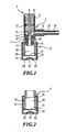
- the milk frothing device 1 has a nozzle part 2 and a foaming attachment 3.
- the nozzle part 2 comprises a steam connection 4, a milk connection 5, a suction chamber 6 and a nozzle section 7.
- the steam connection 4 serves to receive the steam outlet pipe 8 with the steam channel 9.
- an O-ring 10 is arranged, which surrounds the Gap between the steam outlet pipe 8 and the Steam connection 4 seals against the environment.
- the outlet opening 11 of the steam channel 9 projects into the suction chamber 6.
- the milk connection 5 has a milk channel 12, which opens laterally into the suction chamber 6.
- the milk connection 5 further has a hose connection 13, on which a flexible hose (not shown) can be pushed, with which the milk connection 5 is connected to a container (not shown) filled with milk.
- the nozzle section 7 adjoins the nozzle opening 14.
- the nozzle portion 7 has an upper nozzle portion 15 and a lower nozzle portion 16, wherein the diameter of the upper nozzle portion 15 is smaller than the diameter of the lower nozzle portion 16.
- the nozzle section 7 further has an outer connection 17 in the form of a shoulder in the cylindrical shell, on which the foaming attachment 3 can be pushed.
- the foaming cap 3 consists of an expansion section 18 and a discharge section 19.
- the expansion section 18 the expansion chamber 20 is formed, which extends between the nozzle section 7 of the nozzle part 2 and the screen 21 arranged on the front side on the expansion section.
- the upper part of the expansion portion 18 is pushed onto the port 17, the nozzle portion 7 protruding slightly into the expansion chamber 20.
- the division of the expansion section 18 in an upper and lower part by means of the step 25 can be clearly seen in Fig. 2.
- the lower part of the expansion section 18 is completely surrounded by the outlet section 19, so that there is a double wall in the region of the expansion chamber 20.
- the outlet section 19 extends below the screen 21 further up to the outlet openings 22. Between the outlet openings 22 and the screen 21, the foaming chamber 23 is formed by the outlet section 19. Between the outlet openings 22, a bulge 24 is formed in the bottom of the outlet portion 19.
- outlet openings 22 In the bottom view of the outlet section 19 shown in FIG. 3 a, the circularly arranged outlet openings 22 can be clearly seen. Six outlet openings 22 are grouped at a uniform distance around the inwardly projecting bulge 24.
- FIGS. 4a and 4b show a further embodiment of a discharge section 19 for use with a milk frothing device 1.
- the bottom of the outlet portion 19 is formed flat.
- six outlet openings 22 are again arranged at an equal distance from one another and to the center of the outlet section 19.
- the milk frothing device 1 is connected via the steam outlet pipe 8 to the steam generator of the coffee maker. Via the steam channel 9 dry steam flows into the suction chamber 6, which is sealed by means of the O-ring 10 between the steam outlet pipe 8 and the steam connection 4 with respect to the environment.
- a negative pressure is generated by means of the steam flowing into the suction pipe, which sucks milk through the milk channel 12 of the milk connection 5 from a container, not shown.
- the milk flowing into the suction chamber 6 mixes here with the water vapor. In this case, the milk is heated and forms, together with the dry steam, a milk-vapor mixture which flows from the suction chamber 6 into the nozzle section 7.
- the milk flowing in laterally into the suction chamber 6 is entrained by the steam jet in the flow direction predetermined by the steam duct 9, here in the vertical direction.
- the milk-vapor mixture flows through the upper nozzle section 15 and the adjoining lower nozzle section 16, whereby in the lower nozzle section 16 the jet can already slightly expand due to the slightly enlarged diameter.
- the jet of the milk-vapor mixture emerging from the nozzle section 7 widens further, so that it strikes the sieve 21 at the end of the expansion chamber 20 as extensively as possible.
- the milk-vapor mixture impinges on the sieve 21 with relatively high kinetic energy.
- the liquid jet is divided many times through the sieve 21.
- the part reflected upward into the expansion chamber 20 is extreme low and is immediately entrained by the inflowing liquid jet again in the direction of the screen 21.
- an intensive foaming of the milk-vapor mixture is achieved in the foaming chamber 23.
- the forming foam can settle in the foaming chamber 23 and exit at the outlet openings 22 as a closed and relatively uniform foam jet.
- the outlet conditions of the foam forming in the foaming chamber and impinging on the bottom of the outlet section 19 vary, whereby the foam properties of the outflowing milk foam can be adjusted.
- the milk frother device 1 according to the invention for use with a coffee maker can be produced in simple form from a plurality of parts, nozzle part 2, expansion section 18 and outlet section 19, made of heat-resistant plastic.
- the nozzle part 2 is preferably made of a rigid material in view of the negative pressure forming in the suction chamber 6, while the expansion section 18 and the outlet section 19 of the Schwarzumaufsatzes 3 can also be made of an elastic or partially elastic material.
- the screen 21 can be attached in a relatively simple manner to the end face of the expansion section 18 by welding.
- water can be conveyed into the suction chamber 6 after each milk foaming process in the same way through the milk connection 5 and effect the cleaning of the components contaminated with milk.
- nozzle part 2 expansion section 18 with sieve 21 and outlet section 19 with outlet openings 22, the parts can be taken apart in the simplest way and then carefully cleaned by hand or in a dishwasher.
Landscapes
- Engineering & Computer Science (AREA)
- Food Science & Technology (AREA)
- Apparatus For Making Beverages (AREA)
- Dairy Products (AREA)
Abstract
Description
Die vorliegende Erfindung betrifft eine Milchschäumvorrichtung, gemäß dem Oberbegriff von Anspruch 1.The present invention relates to a milk frothing device according to the preamble of
Einfache Vorrichtungen zum Erzeugen von Milchschaum weisen eine mit dem Dampferzeuger des Kaffeezubereiters verbundene Dampfdüse auf, an dessen Auslass sich mehrere Düsenöffnungen befinden. Diese Dampfdüse wird zum Erzeugen des Milchschaums unter den Flüssigkeitsspiegel eines mit Milch gefüllten Gefäßes getaucht und der Milchbehälter in einer Aufwärts- und Abwärtsbewegung um die Dampfdüsen herum bewegt, um die gewünschte Aufschäumung der Milch zu erreichen. Die Handhabung einer solchen Dampfdüse erfordert eine gewisse Erfahrung, wobei sich ein Aufspritzen der Milch trotzdem kaum vermeiden lässt. Nachteilig bei einer solchen Dampfdüse ist es weiter, dass nur kleine Mengen von Milch in entsprechend kleinen Behältern aufgeschäumt werden können.Simple devices for producing milk froth have a steam nozzle connected to the steam generator of the coffee maker, at the outlet of which there are a plurality of nozzle openings. This steam nozzle is submerged under the liquid level of a milk-filled vessel to produce the milk froth, and the milk container is moved in an up and down motion around the steam nozzles to achieve the desired frothing of the milk. The handling of such a steam nozzle requires some experience, with an injection of the milk can hardly be avoided anyway. A disadvantage of such a steam nozzle, it is further that only small amounts of milk can be foamed in accordance with small containers.
Weitere einfache Vorrichtungen weisen ein mit dem Dampferzeuger verbundenes Dampfrohr auf, an dessen Auslass sich eine Düsenanordnung mit Kanälen zum Ansaugen von Luft und Milch befindet. Diese Düsenanordnung wird zum Erzeugen des Milchschaums wiederum unter den Flüssigkeitsspiegel eines mit Milch gefüllten Gefäßes getaucht. Wenn die Düsenanordnung mit Dampf durchströmt wird, werden Luft und Milch durch die entsprechenden Kanäle in der Düsenanordnung angesaugt und der gewünschte Milchschaum erzeugt. Zwar können diese Vorrichtungen gegenüber einer einfachen Dampfdüse die Handhabung erleichtern, jedoch bleiben die Nachteile im Wesentlichen bestehen.Further simple devices comprise a steam pipe connected to the steam generator, at whose outlet there is a nozzle arrangement with ducts for sucking air and milk. This nozzle arrangement is again submerged under the liquid level of a vessel filled with milk in order to produce the frothy milk. When the nozzle assembly is traversed by steam, air and milk are sucked through the respective channels in the nozzle assembly and generates the desired milk foam. Although these devices can facilitate handling compared with a simple steam nozzle, the disadvantages remain essentially the same.
Aus der
Aus der
Eine weitere Milchschäumvorrichtung für einen Kaffeezubereiter mit Dampferzeuger beschreibt die
Eine gattungsgemäße Milchschäumvorrichtung ist aus der
Die im Stand der Technik bekannten Milchschäumvorrichtungen für Kaffeemaschinen sind entweder schwer zu bedienen, bzw. trotz aufwendigen Konstruktionen schwer einzustellen, ohne dabei die gewünschte Milchschaum-Konsistenz zu gewährleisten. Auch ist insbesondere bei aufwendigen Konstruktionen die Reinigung der Milchschäumvorrichtungen häufig mit Problemen behaftet.The known in the prior art Milchschäumvorrichtungen for coffee machines are either difficult to use, or difficult to set despite elaborate constructions, without ensuring the desired milk foam consistency. Also, especially in complex constructions, the cleaning of the milk foaming devices often has problems.
Der vorliegenden Erfindung liegt daher die Aufgabe zugrunde, eine Milchschäumvorrichtung bereitzustellen, auf einer relativ einfachen Konstruktion beruht und trotzdem eine möglichst gute Schaumerzeugung und eine einfache Reinigung ermöglicht.The present invention is therefore an object of the invention to provide a milk frothing, based on a relatively simple construction and still allows the best possible foam generation and easy cleaning.
Diese Aufgabe wird für eine gattungsgemäße Milchschäumvorrichtung durch die Merkmale des kennzeichnenden Teils von Anspruch 1 gelöst.This object is achieved by a generic milk frothing device the features of the characterizing part of
Durch die erfindungsgemäße Ausgestaltung der Milchschäumvorrichtung eines Kaffeezubereiters wird ein Aufschäumen der angesaugten Milch ohne eine vorherige Beimischung von Luft oder ein Verwirbeln des Milch-Dampfgemisches mit Luft erreicht. Dabei wird in der Milchschäumvorrichtung vor dem Sieb, d. h. weder in der Saugkammer noch in der Düse ein Ansaugen oder eine Beimischung von Luft bewirkt. Als Sieb ist jeder Strahlteiler mit einer Gitterstruktur verwendbar, beispielsweise auch mechanisch oder in einem Ätzverfahren hergestellte Lochscheiben, wobei das Sieb auch durch mehrere beabstandete Lagen eines Strahlteilers mit Gitterstruktur ausgebildet sein kann.Due to the inventive design of the milk foaming of a coffee maker foaming of the sucked milk is achieved without a prior admixing of air or a swirling of the milk-vapor mixture with air. It is in the milk frother in front of the screen, d. H. neither in the suction chamber nor in the nozzle causes an intake or an admixture of air. As sieve, each beam splitter can be used with a lattice structure, for example, perforated discs produced mechanically or by etching, wherein the sieve can also be formed by a plurality of spaced layers of a beam splitter with lattice structure.
Zur Erzeugung eines feinen und gleichmäßigen Milchschaums kann die Milchschäumvorrichtung eine Schäumkammer umfassen, die zwischen dem Sieb und der mindestens einen Auslauföffnung angeordnet ist. Dabei kann bevorzugt die Milchschäumvorrichtung ein Auslaufabschnitt umfassen, in dem die Schäumkammer und die mindestens eine Auslauföffnung ausgebildet sind. Dadurch kann die zur Ausbildung der Milchschäumvorrichtung notwendige Anzahl von Bauteilen verringert werden. Weiter ist durch den Auslaufabschnitt eine feinere Abstimmung zwischen der Schäumkammer und der Auslauföffnung möglich.To produce a fine and uniform milk foam, the milk frothing device may comprise a foaming chamber which is arranged between the sieve and the at least one outlet opening. In this case, the milk foaming device may preferably comprise an outlet section, in which the foaming chamber and the at least one outlet opening are formed. As a result, the number of components necessary for the formation of the milk foaming device can be reduced. Furthermore, a finer coordination between the foaming chamber and the outlet opening is possible through the outlet section.
Eine günstige Ausführungsform sieht vor, dass die Milchschäumvorrichtung eine Ausdehnungskammer umfasst, die zwischen dem Düsenabschnitt und dem Sieb angeordnet ist. Diese Ausdehnungskammer ermöglicht eine bessere, großflächige Verteilung des aus dem Düsenabschnitt austretenden Dampf-Milchgemisches vor dem Auftreffen auf das Sieb und gewährleistet so eine optimale Schaumerzeugung. Mittels der Ausdehnungskammer ist weiter der Abstand zwischen der Düse und dem Sieb gut einstellbar.A favorable embodiment provides that the milk frothing device comprises an expansion chamber, which is arranged between the nozzle section and the screen. This expansion chamber allows a better, large-scale distribution of emerging from the nozzle section steam-milk mixture before hitting the wire, thus ensuring optimum foam generation. By means of the expansion chamber is further the distance between the nozzle and the screen well adjustable.
Eine vorteilhafte Ausgestaltung sieht vor, dass ein Ausdehnungsabschnitt vorgesehen ist, in dem die Ausdehnungskammer ausgebildet ist, wobei das Sieb stromabwärts der Ausdehnungskammer an dem Ausdehnungsabschnitt angeordnet ist. Durch den Ausdehnungsabschnitt lässt sich in einfacher Weise eine Ausdehnungskammer ausbilden, die durch das an dem Ausdehnungsabschnitt ausgebildete Sieb begrenzt ist. So kann auch für die Anordnung des Siebes auf zusätzliche Bauteile verzichtet werden. Auch lässt sich auf diese Weise das Sieb in Bezug auf die Ausdehnungskammer gut ausrichten. Für eine sichere Befestigung des Siebs kann das Sieb fest mit dem Ausdehnungsabschnitt verbunden sein, bevorzugt verschweißt sein. Dabei kann der Ausdehnungsabschnitt bevorzugt aus Kunststoff hergestellt sein, wodurch sich eine sehr einfache Befestigungsmöglichkeit durch das Verschweißen des Siebes mit dem stirnseitigen Rand des Ausdehnungsabschnitts ergibt. So ist eine besonders günstige Herstellung des Ausdehnungsabschnitts mit einem integrierten Sieb möglich.An advantageous embodiment provides that an expansion section is provided, in which the expansion chamber is formed, wherein the wire is arranged downstream of the expansion chamber at the expansion section. By the expansion section can be easily formed an expansion chamber, which is limited by the screen formed on the expansion section. So can be dispensed with additional components for the arrangement of the screen. Also In this way, the strainer can be aligned well with respect to the expansion chamber. For a secure attachment of the screen, the screen may be firmly connected to the expansion section, preferably welded. In this case, the expansion section can preferably be made of plastic, resulting in a very simple mounting option by welding the screen to the front edge of the expansion section. Thus, a particularly favorable production of the expansion section with an integrated sieve is possible.
Eine zweckmäßige Variante sieht vor, dass das Sieb entfernbar gegenüber dem Düsenabschnitt angeordnet ist. Dies ermöglicht eine einfache Reinigung des Siebes sowie der gesamten Düse.A suitable variant provides that the sieve is arranged removably opposite the nozzle section. This allows easy cleaning of the screen and the entire nozzle.
Um die Reinigung des Siebes zu verbessern und eine Reinigung der Schäumkammer zu ermöglichen, kann ebenfalls das Sieb entfernbar gegenüber der Schäumkammer angeordnet sein.In order to improve the cleaning of the screen and to enable a cleaning of the foaming chamber, the screen can also be arranged removably opposite the foaming chamber.
Eine weitere Ausbildung sieht vor, dass das Sieb aus einer oder mehreren beabstandeten Lagen eines feinmaschigen Gewebes ausgebildet ist. Ein feinmaschiges Gewebe ist eine einfache Form des für die Milchschäumung notwendigen Siebs, das in vielen unterschiedlichen Arten hergestellt wird, von vielen Herstellern beziehbar ist und leicht bearbeitet werden kann. Dabei kann für eine kostengünstige Lösung das feinmaschige Gewebe aus einem temperaturbeständigen Kunststoff hergestellt sein. Weiter kann das feinmaschige Gewebe in einer stabilen, robusten Ausführungsform aus nicht rostendem Edelstahl hergestellt sein, wodurch das Sieb auch belastenden Betriebsbedingungen gut widerstehen kann.A further embodiment provides that the sieve is formed from one or more spaced layers of a fine-meshed fabric. A fine mesh fabric is a simple form of the screen needed for milk frothing, which is manufactured in many different ways, available from many manufacturers and easy to machine. It can be made of a temperature-resistant plastic for a cost-effective solution, the fine-mesh fabric. Further, in a sturdy, rugged embodiment, the fine mesh fabric can be made of stainless steel, which allows the mesh to withstand severe operating conditions well.
In einer Ausführungsform ist vorgesehen, dass das feinmaschige Gewebe ein Maschenweite/Drahtstärke-Verhältnis von 75/50 bis 140/110, bevorzugt ca. 100/65 aufweist. Versuche haben gezeigt, dass eine Drahtstärke von 50 bis 110 µm, bevorzugt ca. 65 µm, besonders gut geeignet ist das auftreffende Milch-Dampfgemisch zu zerteilen. Dabei wird der auftreffende Fluidstrahl regelrecht zerschnitten, so dass nur ein kleiner Anteil in den stromaufwärts liegenden Abschnitt, üblicherweise die Ausdehnungskammer, reflektiert wird. Darüber hinaus verbleibt bei solch dünnen Fadenstärken auch mehr Raum für die Öffnungen im Sieb und damit für die Öffnung zum Durchtritt des Milch-Dampfgemisches. Parallel zu der Fadenstärke ist für das Sieb eine Maschenweise, bzw. ein Lochdurchmesser, von 75 bis 140 µm, bevorzugt ca. 100 µm, vorgesehen. Durch die vielen Öffnungsränder derartig kleiner Öffnungen entstehen entsprechend viele Verwirbelungskanten, die für die gewünschte Aufschäumung des Milch-Dampfgemisches verantwortlich sind.In one embodiment, it is provided that the fine mesh fabric has a mesh width / wire gauge ratio of 75/50 to 140/110, preferably about 100/65. Experiments have shown that a wire thickness of 50 to 110 microns, preferably about 65 microns, is particularly well suited to divide the impinging milk-vapor mixture. In this case, the impinging fluid jet is literally cut, so that only a small portion in the upstream section, usually the expansion chamber, is reflected. In addition, with such thin thread sizes, more space remains for the openings in the sieve and thus for the opening for the passage of the milk-vapor mixture. Parallel to the thread thickness is for the screen a mesh, or a hole diameter of 75 to 140 microns, preferably about 100 microns, provided. Due to the many opening edges of such small openings correspondingly many swirl edges, which are responsible for the desired foaming of the milk-vapor mixture.
Um eine gute Dampfführung in der Milchschäumvorrichtung des Kaffeezubereiters zu ermöglichen, können das Dampfauslassrohr und der Düsenabschnitt koaxial zueinander angeordnet sein. Durch diese Anordnung kann der Dampfstrahl in der Saugkammer mit möglichst geringen Verlusten zur Düse weitergeleitet werden.In order to enable a good steam guide in the milk frothing device of the coffee maker, the steam outlet pipe and the nozzle portion may be arranged coaxially with each other. By virtue of this arrangement, the steam jet in the suction chamber can be forwarded to the nozzle with the least possible losses.
Vorteilhafterweise kann der Düsenabschnitt mindestens einen oberen und unteren Düsenabschnitt mit unterschiedlichen Durchmessern umfassen, wobei bevorzugt der an die Saugkammer anschließende obere Düsenabschnitt den kleinsten Durchmesser aufweist. Hierdurch wird bereits in der Düse eine gewisse Aufweitung des Dampf-Milchstrahls ermöglicht. Durch diese Düsenform kann die üblicher Weise anschließende Ausdehnungskammer kürzer ausgeführt werden und so die gesamte Milchschäumvorrichtung kompakter ausgebildet sein.Advantageously, the nozzle section may comprise at least one upper and lower nozzle section with different diameters, wherein preferably the upper nozzle section adjoining the suction chamber has the smallest diameter. As a result, a certain expansion of the steam-milk jet is already possible in the nozzle. By this nozzle shape, the usual way subsequent expansion chamber can be made shorter and so the entire milk foaming device be made more compact.
Eine bevorzugte Ausführungsform sieht vor, dass das Verhältnis der Durchmesser des Düsenabschnitts mit dem kleinsten Durchmesser zum Innendurchmesser des Dampfauslassrohrs 1,5 bis 3, bevorzugt ca. 2, beträgt. Durch das vergrößerte Durchmesserverhältnis kann der gesamte aus dem Dampfauslassrohr austretende trockene Wasserdampf gut über den Düseneintritt in die Düse geführt werden, ohne dass ein Führungstrichter notwendig ist. Auch kann die Volumenzunahme des Dampfstrahls in der Saugkammer durch die angesaugte Milch problemlos mit aufgenommen werden.A preferred embodiment provides that the ratio of the diameter of the nozzle section with the smallest diameter to the inner diameter of the steam outlet pipe 1.5 to 3, preferably about 2, is. Due to the increased diameter ratio, all of the dry water vapor leaving the steam outlet pipe can be fed well into the nozzle via the nozzle inlet, without the need for a guide funnel. Also, the volume increase of the steam jet in the suction chamber can be easily absorbed by the sucked milk.
Eine weitere Ausgestaltung sieht vor, dass das Verhältnis des Innendurchmessers des Dampfauslassrohrs zum Innendurchmesser der Milchzuleitung 0,5 bis 1, bevorzugt ca. 0,75, beträgt. Dieses Durchmesserverhältnis ermöglicht ein für die Milchaufschäumung geeignetes Verhältnis von Dampf zu Milch.A further embodiment provides that the ratio of the inner diameter of the steam outlet tube to the inner diameter of the milk supply line is 0.5 to 1, preferably about 0.75. This diameter ratio allows a suitable ratio of steam to milk for milk frothing.
Um gute Aufschäumbedingungen durch ein großflächiges Auftreffen des Milch-Dampfgemisches auf das Sieb zu realisieren kann das Verhältnis des Abstands zwischen dem Düsenabschnitt und dem Sieb zum Durchmesser des Düsenabschnitts mit dem kleinsten Durchmesser 4 bis 6, bevorzugt 4,5 bis 5, betragen.In order to realize good foaming conditions by a large-scale impact of the milk-vapor mixture on the screen, the ratio of the distance between the nozzle portion and the sieve to the diameter of the nozzle portion with the smallest diameter 4 to 6, preferably 4.5 to 5, amount.
Für die Milchschäumvorrichtung üblicher Kaffeezubereiter kann der kleinste Durchmesser des Düsenabschnitts 2,5 bis 3,5 mm, bevorzugt ca. 3 mm, betragen. Durch diese Düsengröße ist die Milchschäumvorrichtung geeignet eine Portion aufgeschäumter Milch in einer für einen üblichen Nutzer ausreichend kurzen Zeit bereitzustellen, ohne einen größer dimensionierten Dampferzeuger zu benötigen. Um eine ausreichende Dampfzufuhr zu gewährleisten, kann der Innendurchmesser des Dampfauslassrohrs 1 bis 2 mm, bevorzugt ca. 1,5 mm, betragen. Mit einem solchen Innendurchmesser ist das Dampfauslassrohr auf die in üblichen Kaffeezubereitem eingesetzten Dampferzeuger abgestimmt.For the milk frother conventional coffee maker, the smallest diameter of the nozzle portion 2.5 to 3.5 mm, preferably about 3 mm, amount. By virtue of this nozzle size, the milk frothing device is suitable for providing a portion of frothed milk in a time that is sufficiently short for a conventional user without requiring a larger-dimensioned steam generator. In order to ensure a sufficient supply of steam, the inner diameter of the
Günstigerweise kann der Innendurchmesser der Milchzuleitung 1,5 bis 2,5 mm, bevorzugt ca. 2 mm, betragen. Dieser Innendurchmesser ermöglicht eine optimale Milchzufuhr zur Saugkammer der Milchschäumvorrichtung bei einer guten Aufschäumung und Erwärmung der Milch auf Trinktemperatur durch die Milchschäumvorrichtung.Conveniently, the inner diameter of the milk supply line 1.5 to 2.5 mm, preferably about 2 mm, amount. This inner diameter enables optimal milk supply to the suction chamber of the milk foaming device with good foaming and heating of the milk to drinking temperature by the milk foaming device.
Für gute Aufschäumbedingungen können der Düsenabschnitt und das Sieb in einem Abstand von 10 bis 18 mm, bevorzugt 12 bis 16 mm, angeordnet sein.For good foaming conditions, the nozzle section and the screen may be arranged at a distance of 10 to 18 mm, preferably 12 to 16 mm.
Zur einfachen Ausgestaltung des Anschlusses an den Dampferzeuger kann die Milchschäumvorrichtung einen Dampfanschluss zum Aufnehmen des Dampfanschlussrohrs aufweisen, wobei zwischen dem Dampfanschluss und dem Dampfauslassrohr mindestens eine Dichtung, bevorzugt mindestens ein O-Ring, vorgesehen ist. Die Einbindung einer Abdichtung zwischen Dampfanschluss und Dampfauslassrohr, bevorzugt in einer umlaufenden Nut des Dampfauslassrohrs, wird eine sichere Dichtfunktion des Dampfanschlusses gewährleistet. Dies ist insbesondere auch im Hinblick auf eine Verbrennungsgefahr unvorsichtiger Benutzer des Kaffeezubereiters von großer Wichtigkeit.For a simple embodiment of the connection to the steam generator, the milk foaming device may have a steam connection for receiving the steam connection pipe, wherein at least one seal, preferably at least one O-ring, is provided between the steam connection and the steam outlet pipe. The integration of a seal between the steam connection and the steam outlet pipe, preferably in a circumferential groove of the steam outlet pipe, ensures a secure sealing function of the steam connection. This is particularly important in view of a risk of burns careless user of the coffee maker of great importance.
Eine zweckmäßige Ausgestaltung sieht vor, dass die Saugkammer eine quasi-elliptische Form aufweist, wobei das Dampfauslassrohr mittig und die Milchzuleitung seitlich in die Saugkammer münden, und der Düsenabschnitt mittig am Boden der Saugkammer angeordnet ist. Die quasi-elliptische Form der Saugkammer bildet gemeinsam mit der Anordnung der Zuleitungen und Auslasse eine wirkungsvolle Ausgestaltung für eine sichere und gleichmäßige Zuleitung der Milch und der Zuführung des Milch-Dampfgemisches zur Düse. Dabei ist als quasi-elliptische Form eine stilisierte Ellipsenform mit graden Abschnitten zu verstehen. Der in Strömungsrichtung untenliegende Boden der Saugkammer ist abgeflacht, wobei der größte Teil des Bodens durch die Düsenöffnung eingenommen wird. An dem Boden schließt sich ein kegelstumpfförmiger Bereich an, der in einen mittleren Ringabschnitt mit gleichbleibendem Durchmesser übergeht, wobei der Ringabschnitt gleichzeitig den größten Durchmesser der quasi-elliptischen Saugkammer bildet, wobei im Bereich dieses Ringabschnitts die Milchzuleitung angeordnet ist. Oberhalb des Ringabschnitts ist wieder ein kegelstumpfförmiger Bereich angeordnet mit einer dem ersten kegelstumpfförmigen Bereich entgegengesetzten Steigung. Dieser zweite kegelstumpfförmige Bereich endet mittig in einem abgeflachten Bereich, in dem die Öffnung des Dampfeintritts angeordnet ist.An expedient embodiment provides that the suction chamber has a quasi-elliptical shape, wherein the steam outlet pipe in the middle and the milk supply line open laterally into the suction chamber, and the nozzle portion is arranged centrally at the bottom of the suction chamber. The quasi-elliptical shape of the suction chamber forms together with the arrangement the supply lines and outlets an effective design for a safe and uniform supply of milk and the supply of milk-vapor mixture to the nozzle. Here, a quasi-elliptical shape is to be understood as a stylized elliptical shape with straight sections. The downstream bottom of the suction chamber is flattened, with most of the bottom occupied by the nozzle opening. At the bottom of a frusto-conical region connects, which merges into a central ring portion with a constant diameter, wherein the ring portion simultaneously forms the largest diameter of the quasi-elliptical suction chamber, wherein in the region of this ring portion, the milk supply line is arranged. Above the ring section, a frustoconical region is again arranged with a slope opposite the first frustoconical region. This second frusto-conical region ends centrally in a flattened region in which the opening of the steam inlet is arranged.
Für eine sichere Dampfzufuhr in die Saugkammer kann das Dampfauslaufrohr in die Saugkammer vorstehen, bevorzugt stromabwärts über die Milchzuleitung vorstehen. Durch ein solches Vorstehen des oberen abgeflachten, mit der Öffnung des Dampfeintritts versehenen Bereichs in die Saugkammer wird bei einer nur geringen Volumenabnahme der Saugkammer das Dampfauslassrohr näher an die Düse herangeführt und damit ein besseres Einströmverhalten des Dampfes, bzw. des Milch-Dampfgemisches, in die Düse erreicht. Mit dem Vorstehen des Dampfauslassrohrs über die Milchzuleitung wird trotz eines weiterhin relativ großen Volumens der Saugkammer eine sehr kompakte Bauweise erreicht. Dieser Hinterschnitt ermöglicht eine extrem nahe Anordnung des Dampfauslassrohrs zur Düse und so ein nahezu verlustfreies Einströmverhalten des Dampfes, bzw. des Milch-Dampfgemisches, in die Düse.For a safe supply of steam into the suction chamber, the steam outlet pipe may protrude into the suction chamber, preferably projecting downstream via the milk supply line. By such a projection of the upper flattened, provided with the opening of the steam inlet area in the suction chamber is at a small decrease in volume of the suction chamber, the steam outlet closer to the nozzle and thus a better inflow of the steam, or the milk-steam mixture, in the Nozzle reached. With the projection of the steam outlet pipe via the milk supply line, a very compact construction is achieved despite a still relatively large volume of the suction chamber. This undercut allows an extremely close arrangement of the steam outlet pipe to the nozzle and so a virtually lossless inflow of the steam, or the milk-vapor mixture, in the nozzle.
Die Erfindung bezieht sich weiter auf eine Milchschäumvorrichtung nach einem der Ansprüche 1 bis 19 zum Einsatz mit einem Kaffeezubereiter, welche eine stromaufwärts eines Dampfauslassrohrs angeordnete Saugkammer, eine in die Saugkammer mündende Milchzuleitung, einen stromabwärts der Saugkammer angeordneten Düsenabschnitt und mindestens eine Auslauföffnung umfasst, wobei zwischen dem Düsenabschnitt der mindestens einen Auslauföffnung ein Sieb angeordnet ist. Diese Milchschäumvorrichtung ermöglicht ein feinporiges Aufschäumen der angesaugten Milch ohne eine Beimischung von zusätzlicher Luft oder ein Verwirbeln des Milch-Dampfgemisches vor dem Sieb, d. h. in der Saugkammer oder in der Düse. Hierdurch entsteht ein besonders feinporiger Milchschaum, der lange seine aufgeschäumte Struktur bewahrt, ohne zusammenzufallen.The invention further relates to a milk frothing device according to any one of
Im Folgenden werden Ausführungsbeispiele der vorliegenden Erfindung anhand der Zeichnungen näher erläutert. Es zeigen:
- Fig. 1
- eine seitliche Schnittansicht durch eine Milchschäumvorrichtung eines erfindungsgemäßen Kaffeezubereiters,
- Fig. 2
- eine seitliche Schnittansicht des Schäumaufsatzes aus Fig. 1,
- Fig. 3a
- zeigte eine Unteransicht des Auslaufabschnitts aus Fig. 1,
- Fig. 3b
- zeigt eine seitliche Schnittansicht des Auslaufabschnitts aus Fig. 1,
- Fig. 4a
- zeigt eine Unteransicht einer anderen Ausführungsform des Auslaufabschnitts, und
- Fig. 4b
- zeigt eine seitliche Schnittansicht des Auslaufabschnitts aus Fig. 4a.
- Fig. 1
- a side sectional view through a milk frothing device of a coffee maker according to the invention,
- Fig. 2
- 1 is a side sectional view of the foaming cap of FIG. 1,
- Fig. 3a
- 1 shows a bottom view of the discharge section from FIG. 1,
- Fig. 3b
- shows a side sectional view of the spout portion of Fig. 1,
- Fig. 4a
- shows a bottom view of another embodiment of the spout portion, and
- Fig. 4b
- shows a side sectional view of the outlet portion of Fig. 4a.
In Fig. 1 ist die erfindungsgemäße Milchschäumvorrichtung 1 zum Einsatz mit einem Kaffeezubereiter dargestellt. Der Kaffeezubereiter verfügt über ansonsten im Stand der Technik bestens bekannte Merkmale, wie Wasserbehälter, Durchlauferhitzer oder Boiler, eine Brüheinheit, einen Dampferzeuger, etc.. Die dargestellte Milchschäumvorrichtung 1 dient zum Aufschäumen und gleichzeitigem Erwärmen von Milch. Dazu weist die Milchschäumvorrichtung 1 einen Düsenteil 2 und einen Schäumaufsatz 3 auf.In Fig. 1, the
Der Düsenteil 2 umfasst einen Dampfanschluss 4, einen Milchanschluss 5, eine Saugkammer 6 und einen Düsenabschnitt 7. Der Dampfanschluss 4 dient zur Aufnahme des Dampfauslassrohrs 8 mit dem Dampfkanal 9. In einer Nut des Dampfauslassrohrs 8 ist ein O-Ring 10 angeordnet, der den Spalt zwischen dem Dampfauslassrohr 8 und dem Dampfanschluss 4 gegenüber der Umgebung abdichtet. Die Auslassöffnung 11 des Dampfkanals 9 steht in die Saugkammer 6 vor. Der Milchanschluss 5 weist einen Milchkanal 12 auf, der seitlich in die Saugkammer 6 mündet. Der Milchanschluss 5 weist weiter einen Schlauchanschluss 13 auf, auf den ein flexibler Schlauch (nicht gezeigt) aufschiebbar ist, mit dem der Milchanschluss 5 mit einem mit Milch gefüllten Behälter (nicht gezeigt) verbunden ist.The
Am Boden der Saugkammer 6, die in Form von zwei Kegelstümpfen und einem zwischen diesen Kegelstümpfen angeordneten Ringabschnitt ausgeformt ist, wobei die Stirnseiten der Kegelstümpfe mit den größeren Durchmessern an den mittleren Ring angrenzt und die Auslassöffnung 11 des Dampfauslassrohrs 8 von der oberen Stirnfläche der Saugkammer 6 in die Saugkammer 6 vorsteht, grenzt der Düsenabschnitt 7 mit der Düsenöffnung 14 an. Der Düsenabschnitt 7 weist einen oberen Düsenabschnitt 15 und einen unteren Düsenabschnitt 16 auf, wobei der Durchmesser des oberen Düsenabschnitts 15 kleiner als der Durchmesser des unteren Düsenabschnitts 16 ist. Der Düsenabschnitt 7 weist weiter einen äußeren Anschluss 17 in Form eines Absatzes im zylinderförmigen Mantel auf, auf dem der Schäumaufsatz 3 aufschiebbar ist.At the bottom of the
Der Schäumaufsatz 3 besteht aus einem Ausdehnungsabschnitt 18 und einem Auslaufabschnitt 19. In dem Ausdehnungsabschnitt 18 ist die Ausdehnungskammer 20 ausgebildet, die sich zwischen dem Düsenabschnitt 7 des Düsenteils 2 und dem stirnseitig auf dem Ausdehnungsabschnitt angeordneten Siebes 21 erstreckt. Der obere Teil des Ausdehnungsabschnitts 18 ist auf dem Anschluss 17 aufgeschoben, wobei der Düsenabschnitt 7 leicht in die Ausdehnungskammer 20 vorsteht. Die Aufteilung des Ausdehnungsabschnitts 18 in einen oberen und unteren Teil mittels der Stufe 25 ist deutlich in Fig. 2 zu erkennen. Der untere Teil des Ausdehnungsabschnitts 18 ist vollständig von dem Auslaufabschnitt 19 umgeben, so dass sich im Bereich der Ausdehnungskammer 20 eine doppelte Wandung ergibt. Der Auslaufabschnitt 19 erstreckt sich unterhalb des Siebes 21 weiter bis zu den Auslauföffnungen 22. Zwischen den Auslauföffnungen 22 und dem Sieb 21 ist durch den Auslaufabschnitt 19 die Schäumkammer 23 ausgebildet. Zwischen den Auslauföffnungen 22 ist im Boden des Auslaufabschnitts 19 eine Aufwölbung 24 ausgebildet.The foaming
In der in Fig. 3a gezeigten Unteransicht des Auslaufabschnitts 19 sind deutlich die kreisförmig angeordneten Auslauföffnungen 22 zu sehen. Sechs Auslauföffnungen 22 gruppieren sich dabei in einem gleichmäßigen Abstand um die nach innen vorstehende Aufwölbung 24.In the bottom view of the
In den Fig. 4a und 4b ist eine weitere Ausführungsform eines Auslaufabschnittes 19 für die Verwendung mit einer Milchschäumvorrichtung 1 gezeigt. Hierbei ist der Boden des Auslaufabschnitts 19 flächig ausgebildet. Auch hier sind wiederum sechs Auslauföffnungen 22 in einem gleichen Abstand zueinander und zur Mitte des Auslaufabschnitts 19 angeordnet.FIGS. 4a and 4b show a further embodiment of a
Im Folgenden wird die Wirkung und Funktionsweise der oben beschriebenen Milchschäumvorrichtung 1 näher erläutert.In the following, the effect and operation of the
Die Milchschäumvorrichtung 1 ist über das Dampfauslassrohr 8 mit dem Dampferzeuger des Kaffeezubereiters verbunden. Über den Dampfkanal 9 strömt trockener Wasserdampf in die Saugkammer 6, die mittels des O-Rings 10 zwischen dem Dampfauslassrohr 8 und dem Dampfanschluss 4 gegenüber der Umgebung abgedichtet ist. Unter Ausnutzung des Venturi-Prinzips wird mittels des in das Saugrohr einströmenden Dampfes ein Unterdruck erzeugt, der durch den Milchkanal 12 des Milchanschlusses 5 Milch aus einem nicht gezeigten Behälter ansaugt. Die in die Saugkammer 6 einströmende Milch vermischt sich hier mit dem Wasserdampf. Dabei wird die Milch erwärmt und bildet zusammen mit dem trockenen Dampf ein Milch-Dampfgemisch, das aus der Saugkammer 6 in den Düsenabschnitt 7 strömt. Dabei wird die seitlich in die Saugkammer 6 einströmende Milch von dem Dampfstrahl in die durch den Dampfkanal 9 vorgegebene Strömungsrichtung, hier in Vertikalrichtung, mitgerissen. Das Milch-Dampfgemisch strömt durch den oberen Düsenabschnitt 15 und den anschließenden unteren Düsenabschnitt 16, wobei sich im unteren Düsenabschnitt 16 der Strahl durch den leicht vergrößerten Durchmesser bereits ein wenig aufweiten kann. In der sich anschließenden Ausdehnungskammer 20 weitet sich der Strahl des aus dem Düsenabschnitt 7 austretenden Milch-Dampfgemisches weiter auf, so dass er möglichst großflächig auf das Sieb 21 am Ende der Ausdehnungskammer 20 trifft. Das Milch-Dampfgemisch trifft mit relativ hoher kinetischer Energie auf das Sieb 21. Durch das Sieb 21 wird der Flüssigkeitsstrahl vielfach zerteilt. Dabei ist der nach oben in die Ausdehnungskammer 20 reflektierte Teil äußerst gering und wird durch den nachströmenden Flüssigkeitsstrahl sofort wieder in Richtung des Siebs 21 mitgerissen. Durch die aus den Maschen des Siebs 21 austretende Vielzahl von Teilstrahlen wird in der Schäumkammer 23 eine intensive Verschäumung des Milch-Dampfgemisches erreicht. Der sich bildende Schaum kann sich in der Schäumkammer 23 beruhigen und an den Auslauföffnungen 22 als geschlossener und relativ gleichmäßiger Schaumstrahl austreten.The
Je nach Ausbildung des Bodenbereichs des Auslaufabschnitts 19, als ebener Boden oder mit einer Aufwölbung 24, lassen die Auslaufbedingungen des sich in der Schäumkammer bildenden und auf den Boden des Auslaufabschnitts 19 auftreffenden Schaums variieren, wodurch sich die Schaumeigenschaften des auslaufenden Milchschaums einstellen lassen.Depending on the design of the bottom region of the
Durch die weit in die Saugkammer 6 vorstehende Auslassöffnung 11 des Dampfkanals 9 ergibt sich nur ein geringer Abstand zur Düsenöffnung 14, wodurch sich der Dampfstrahl trotz des Einflusses der seitlich einströmenden und von dem Dampfstrahl angesaugten Milch leicht bis zur Düsenöffnung 14 führen lässt. So kann auf eine trichterförmige Öffnung des Düsenabschnitts 7 verzichtet werden. Durch die Hinterscheidung des Milchkanals 12, d. h. das Vorstehen der Auslauföffnung 11 in Strömungsrichtung gegenüber dem Milchkanal 12, wird die Führungseigenschaft nochmals verbessert, da die auf dem Milchkanal 12 seitlich einströmende Milch nicht direkt in den Dampfstrahl einströmen kann.By far into the
Die erfindungsgemäße Milchschäumvonichtung 1 zum Einsatz mit einem Kaffeezubereiter kann in einfacher Form aus mehreren Teilen, Düsenteil 2, Ausdehnungsabschnitt 18 und Auslaufabschnitt 19, aus temperaturbeständigem Kunststoff hergestellt werden. Dabei ist das Düsenteil 2 im Hinblick auf den sich in der Saugkammer 6 bildenden Unterdruck bevorzugt aus einem starren Material herzustellen, während der Ausdehnungsabschnitt 18 und der Auslaufabschnitt 19 des Schäumaufsatzes 3 auch aus einem elastischem oder teilelastischem Werkstoff gefertigt werden können. Dabei lässt sich das Sieb 21 je nach Werkstoff in relativ einfacher Weise durch verschweißen auf der Stirnseite des Ausdehnungsabschnitts 18 anbringen.The
Zum Reinigen der Milchschäumvorrichtung 1 kann nach jedem Milchschäumvorgang in gleicher Weise durch den Milchanschluss 5 Wasser in die Saugkammer 6 gefördert werden und die Säuberung der mit Milch kontaminierten Bauteile bewirken. Zur ausgiebigen Reinigung der einzelnen Bauteile, Düsenteil 2, Ausdehnungsabschnitt 18 mit Sieb 21 und Auslaufabschnitt 19 mit Auslauföffnungen 22, können die Teile in einfachster Weise auseinander genommen werden und dann sorgfältig per Hand oder in einer Spülmaschine gesäubert werden.To clean the
Claims (24)
- Milk foaming device (1) for use with a coffee-making machine, comprising a suction chamber (6) disposed downstream of a steam outlet pipe (8), a milk inlet line (5) opening into the suction chamber (6), a nozzle portion (7) disposed downstream of the suction chamber (6) and at least one outlet orifice (22), wherein a sieve (21) is disposed between the nozzle portion (7) and the at least one outlet orifice (22),
characterised in that the milk foaming device (1) has a foaming chamber (23) disposed between the sieve (21) and the at least one outlet orifice (22). - Milk foaming device (1) as claimed in claim 1,
characterised in that the milk foaming device (1) has an outlet portion (19) forming the foaming chamber (23) and the at least one outlet orifice (22). - Milk foaming device (1) as claimed in claim 1 or 2,
characterised in that the milk foaming device (1) has an expansion chamber (20) disposed between the nozzle portion (7) and the sieve (21). - Milk foaming device (1) as claimed in claim 3,
characterised in that an expansion portion (18) is provided in which the expansion chamber (20) is formed and the sieve (21) is disposed on the expansion portion (18) downstream of the expansion chamber (20). - Milk foaming device (1) as claimed in claim 4,
characterised in that the sieve (21) is fixedly connected, preferably welded, to the expansion portion (18). - Milk foaming device (1) as claimed in one of claims 1 to 5,
characterised in that the sieve (21) is disposed so that it can be removed from the nozzle portion (7). - Milk foaming device (1) as claimed in one of claims 1 to 6,
characterised in that the sieve (21) is disposed so that it can be removed from the foaming chamber (23). - Milk foaming device (1) as claimed in one of claims 1 to 7,
characterised in that the sieve (21) is constructed in the form of one or more spaced apart layers of a fine-meshed fabric. - Milk foaming device (1) as claimed in claim 8,
characterised in that the fine-meshed fabric is made from a temperature-resistant plastic. - Milk foaming device (1) as claimed in claim 8,
characterised in that the fine-meshed fabric is made from stainless steel. - Milk foaming device (1) as claimed in one of claims 8 to 10,
characterised in that the fine-meshed fabric has a mesh width/wire thickness ratio of 75/50 to 140/110, preferably approximately 100/65. - Milk foaming device (1) as claimed in one of claims 1 to 11,
characterised in that the nozzle portion (7) comprises at least an upper and a lower nozzle portion (15, 16) of differing diameters, and the upper nozzle portion (15) adjoining the suction chamber (6) preferably has the smallest diameter. - Milk foaming device (1) as claimed in claim 12,
characterised in that the ratio of the diameter of the nozzle portion (15) with the smallest diameter to the internal diameter of the steam outlet pipe (8) is 1.5 to 3, preferably approximately 2. - Coffee-making machine as claimed in claim 12 or 13,
characterised in that the ratio of the internal diameter of the steam outlet pipe (8) to the internal diameter of the milk inlet line (5) is 0.5 to 1, preferably approximately 0.75. - Milk foaming device (1) as claimed in one of claims 12 to 14,
characterised in that the ratio of the distance between the nozzle portion (7) and the sieve (21) to the diameter of the top nozzle portion (15) with the smallest diameter is 4 to 6, preferably 4.5 to 5. - Milk foaming device (1) as claimed in one of claims 12 to 15,
characterised in that the smallest diameter of the nozzle portion (7) is 2.5 to 3.5 mm, preferably approximately 3 mm. - Milk foaming device (1) as claimed in one of claims 1 to 16,
characterised in that the internal diameter of the steam outlet pipe (8) is 1 to 2 mm, preferably approximately 1.5 mm. - Milk foaming device (1) as claimed in one of claims 1 to 17,
characterised in that the internal diameter of the milk inlet line (5) is 1.5 to 2.5 mm, preferably approximately 2 mm. - Milk foaming device (1) as claimed in one of claims 1 to 18,
characterised in that the nozzle portion (7) and the sieve (2) are disposed at a distance of 10 to 18 mm, preferably 12 to 16 mm. - Coffee-making machine with a steam generator and a milk foaming device (1) as claimed in one of claims 1 to 19, with a steam outlet pipe (8) which is connected to the milk foaming device (1).
- Coffee-making machine as claimed in claim 20,
characterised in that the steam outlet pipe (8) and the nozzle portion (7) are disposed coaxially with one another. - Coffee-making machine as claimed in claim 20 or 21,
characterised in that the milk foaming device (1) has a steam connector (4) for accommodating the steam connector pipe (8) and at least one seal, preferably at least one O-ring (10), is provided between the steam connector (4) and the steam outlet pipe (8). - Coffee-making machine as claimed in one of claims 20 to 22,
characterised in that the suction chamber (6) has a quasi-elliptical shape and the steam outlet pipe (8) opens centrally and the milk inlet line (5) opens from the side into the suction chamber (6), and the nozzle portion (7) is disposed centrally on the base of the suction chamber. - Coffee-making machine as claimed in one of claims 20 to 23,
characterised in that the steam outlet pipe (8) projects into the suction chamber (6), preferably downstream via the milk inlet line (5).
Applications Claiming Priority (1)
| Application Number | Priority Date | Filing Date | Title |
|---|---|---|---|
| DE202004014737U DE202004014737U1 (en) | 2004-09-22 | 2004-09-22 | Milk frother with bubble former |
Publications (3)
| Publication Number | Publication Date |
|---|---|
| EP1639925A2 EP1639925A2 (en) | 2006-03-29 |
| EP1639925A3 EP1639925A3 (en) | 2006-05-24 |
| EP1639925B1 true EP1639925B1 (en) | 2007-11-14 |
Family
ID=35462329
Family Applications (1)
| Application Number | Title | Priority Date | Filing Date |
|---|---|---|---|
| EP05020606A Not-in-force EP1639925B1 (en) | 2004-09-22 | 2005-09-21 | Milk foamer with device for forming bubbles |
Country Status (3)
| Country | Link |
|---|---|
| EP (1) | EP1639925B1 (en) |
| AT (1) | ATE377994T1 (en) |
| DE (2) | DE202004014737U1 (en) |
Cited By (1)
| Publication number | Priority date | Publication date | Assignee | Title |
|---|---|---|---|---|
| CN104146613A (en) * | 2014-08-18 | 2014-11-19 | 群韵饮料机械(上海)有限公司 | Milk foam brewing head for coffee machine |
Families Citing this family (15)
| Publication number | Priority date | Publication date | Assignee | Title |
|---|---|---|---|---|
| DE202006009786U1 (en) | 2006-06-22 | 2007-10-25 | Pav Patentverwertung Kg | milk frother |
| EP2133009A1 (en) * | 2008-06-13 | 2009-12-16 | Koninklijke Philips Electronics N.V. | Device for whisking milk and method for cleaning such a device |
| DE102008058934C5 (en) | 2008-11-25 | 2017-11-09 | Volker Barth | Device for frothing milk |
| DE102010023781B4 (en) * | 2010-06-15 | 2015-09-17 | Volker Barth | Device for foaming a liquid |
| DE102011107622A1 (en) * | 2011-06-30 | 2013-01-03 | WMF Württembergische Metallwarenfabrik Aktiengesellschaft | Foaming unit, in particular for frothing milk, with steam nozzle around it |
| DE102011108810A1 (en) | 2011-07-29 | 2013-01-31 | Volker Barth | Device for foaming a liquid |
| GB2494464B (en) | 2011-09-12 | 2014-12-03 | Kraft Foods R & D Inc | Improvements in and relating to beverage preparation machines |
| US8968449B2 (en) * | 2012-07-04 | 2015-03-03 | Vki Technologies Inc. | Spout, system, and method for producing a foam |
| EP3000363A1 (en) * | 2014-09-24 | 2016-03-30 | Qbo Coffee GmbH | Milk frothing device, beverage preparation system and machine for preparing beverages |
| ES2731879T3 (en) | 2015-03-12 | 2019-11-19 | Gruppo Cimbali Spa | Milk dispensing device |
| EP3245916A1 (en) * | 2016-05-19 | 2017-11-22 | Jura Elektroapparate Ag | Outlet device for a milk foamer |
| IT201600099780A1 (en) * | 2016-10-05 | 2018-04-05 | De Longhi Appliances Srl | VENTURI EFFECT MILK EMULSIFIER DEVICE |
| JP7200480B2 (en) * | 2018-02-06 | 2023-01-10 | 富士電機株式会社 | beverage dispenser |
| IT202000014716A1 (en) * | 2020-06-19 | 2021-12-19 | De Longhi Appliances Srl | COFFEE MACHINE AND METHOD OF BREWING A MILK EMULSION WITH THE SAID COFFEE MACHINE |
| CN115553636B (en) * | 2022-12-07 | 2023-03-24 | 广东新宝电器股份有限公司 | Foaming device, foaming system and beverage machine |
Family Cites Families (6)
| Publication number | Priority date | Publication date | Assignee | Title |
|---|---|---|---|---|
| ES8700918A1 (en) | 1985-01-31 | 1986-11-16 | Spidem Srl | An emulsifier unit particularly for emulsifying steam and milk to prepare cappuccino's and the like beverages. |
| IT240604Y1 (en) * | 1996-04-17 | 2001-04-02 | Quick Italia S R L | STERILIZABLE EMULSIFIER DEVICE |
| DE19705633C2 (en) | 1997-02-14 | 2001-02-22 | Eugster Frismag Ag Romanshorn | Device for producing milk foam for cappuccino |
| DE29702568U1 (en) | 1997-02-14 | 1997-04-03 | Eugster Frismag Ag | Device for producing milk foam for cappuccino |
| DE29817116U1 (en) * | 1998-09-24 | 1998-12-17 | Jura Elektroapparate Ag | Device for producing milk foam for cappuccino |
| DE20204085U1 (en) * | 2002-03-13 | 2002-05-23 | Eugster Frismag Ag Romanshorn | Device for producing milk foam for cappuccino |
-
2004
- 2004-09-22 DE DE202004014737U patent/DE202004014737U1/en not_active Expired - Lifetime
-
2005
- 2005-09-21 AT AT05020606T patent/ATE377994T1/en active
- 2005-09-21 DE DE502005001949T patent/DE502005001949D1/en active Active
- 2005-09-21 EP EP05020606A patent/EP1639925B1/en not_active Not-in-force
Non-Patent Citations (1)
| Title |
|---|
| None * |
Cited By (1)
| Publication number | Priority date | Publication date | Assignee | Title |
|---|---|---|---|---|
| CN104146613A (en) * | 2014-08-18 | 2014-11-19 | 群韵饮料机械(上海)有限公司 | Milk foam brewing head for coffee machine |
Also Published As
| Publication number | Publication date |
|---|---|
| DE502005001949D1 (en) | 2007-12-27 |
| DE202004014737U1 (en) | 2006-02-09 |
| EP1639925A2 (en) | 2006-03-29 |
| EP1639925A3 (en) | 2006-05-24 |
| ATE377994T1 (en) | 2007-11-15 |
Similar Documents
| Publication | Publication Date | Title |
|---|---|---|
| EP1639925B1 (en) | Milk foamer with device for forming bubbles | |
| EP0575762B1 (en) | Device preparing foamed milk for cappuccino | |
| DE60209939T2 (en) | BEVERAGE DEVICE FOR PREPARING A BEVERAGE WITH A LAYERING LAYER | |
| EP2606782B1 (en) | Coffee/espresso machine with a milk foaming device for cappuccino | |
| DE4445436C2 (en) | Frothing device | |
| EP2329749B1 (en) | Coffee machine | |
| EP1115317A1 (en) | Device for producing milk froth for cappuccino | |
| DE2401127C3 (en) | Fluidic oscillator | |
| EP1820429B1 (en) | Device for creating frothed milk | |
| DE2510397C2 (en) | Apparatus for texturing yarn with a compressed air nozzle | |
| DE4037366A1 (en) | Espresso coffee machine with foam producing element - uses steam as drive for foaming device | |
| EP1859715A1 (en) | Device for automatic dissolution of instant powder, in particular milk powder, in hot water and in particular for foaming | |
| DE20320605U1 (en) | Pad carrier for a beverage machine, foam unit and beverage machine with such a pad carrier for preparing a beverage with a foam unit using such a pad carrier | |
| EP1787554A2 (en) | Device for the preparation of foam | |
| EP2301396A1 (en) | Coffee/espresso machine with a milk foaming device for cappuccino | |
| DE10050719A1 (en) | Device for producing milk foam for a coffee drink, in particular for cappuccino coffee | |
| EP0520980A1 (en) | Device for foaming and/or emulsifying | |
| DE60119588T2 (en) | Device for heating and emulsifying liquids, in particular drinks | |
| EP3042593B1 (en) | Drinks outlet for a beverage preparation machine | |
| DE19705633C2 (en) | Device for producing milk foam for cappuccino | |
| EP3457901B1 (en) | Outlet device for a milk foamer | |
| DE19611450C1 (en) | Device for heating and foaming milk for preparation of cappuccino drink | |
| EP0638272B1 (en) | Device for a machine for brewing drinks to heat and emulsify liquids | |
| DE10344328B4 (en) | Coffee brewing device with foaming chamber | |
| EP1498059B1 (en) | Coffee brewer with device for forming bubbles |
Legal Events
| Date | Code | Title | Description |
|---|---|---|---|
| PUAI | Public reference made under article 153(3) epc to a published international application that has entered the european phase |
Free format text: ORIGINAL CODE: 0009012 |
|
| AK | Designated contracting states |
Kind code of ref document: A2 Designated state(s): AT BE BG CH CY CZ DE DK EE ES FI FR GB GR HU IE IS IT LI LT LU LV MC NL PL PT RO SE SI SK TR |
|
| AX | Request for extension of the european patent |
Extension state: AL BA HR MK YU |
|
| PUAL | Search report despatched |
Free format text: ORIGINAL CODE: 0009013 |
|
| AK | Designated contracting states |
Kind code of ref document: A3 Designated state(s): AT BE BG CH CY CZ DE DK EE ES FI FR GB GR HU IE IS IT LI LT LU LV MC NL PL PT RO SE SI SK TR |
|
| AX | Request for extension of the european patent |
Extension state: AL BA HR MK YU |
|
| 17P | Request for examination filed |
Effective date: 20060724 |
|
| RIN1 | Information on inventor provided before grant (corrected) |
Inventor name: DIE ERFINDER HABEN AUF IHRE NENNUNG VERZICHTET. |
|
| AKX | Designation fees paid |
Designated state(s): AT BE BG CH CY CZ DE DK EE ES FI FR GB GR HU IE IS IT LI LT LU LV MC NL PL PT RO SE SI SK TR |
|
| GRAP | Despatch of communication of intention to grant a patent |
Free format text: ORIGINAL CODE: EPIDOSNIGR1 |
|
| 111Z | Information provided on other rights and legal means of execution |
Free format text: ATBEBGCHCYCZDEDKEEESFIFRGBGRHUIEISITLTLULVMCNLPLPTROSESISKTR Effective date: 20070710 |
|
| GRAS | Grant fee paid |
Free format text: ORIGINAL CODE: EPIDOSNIGR3 |
|
| GRAA | (expected) grant |
Free format text: ORIGINAL CODE: 0009210 |
|
| AK | Designated contracting states |
Kind code of ref document: B1 Designated state(s): AT BE BG CH CY CZ DE DK EE ES FI FR GB GR HU IE IS IT LI LT LU LV MC NL PL PT RO SE SI SK TR |
|
| REG | Reference to a national code |
Ref country code: GB Ref legal event code: FG4D Free format text: NOT ENGLISH |
|
| REG | Reference to a national code |
Ref country code: CH Ref legal event code: EP |
|
| REG | Reference to a national code |
Ref country code: IE Ref legal event code: FG4D Free format text: LANGUAGE OF EP DOCUMENT: GERMAN |
|
| REG | Reference to a national code |
Ref country code: CH Ref legal event code: NV Representative=s name: ISLER & PEDRAZZINI AG |
|
| REF | Corresponds to: |
Ref document number: 502005001949 Country of ref document: DE Date of ref document: 20071227 Kind code of ref document: P |
|
| PG25 | Lapsed in a contracting state [announced via postgrant information from national office to epo] |
Ref country code: ES Free format text: LAPSE BECAUSE OF FAILURE TO SUBMIT A TRANSLATION OF THE DESCRIPTION OR TO PAY THE FEE WITHIN THE PRESCRIBED TIME-LIMIT Effective date: 20080225 Ref country code: SE Free format text: LAPSE BECAUSE OF FAILURE TO SUBMIT A TRANSLATION OF THE DESCRIPTION OR TO PAY THE FEE WITHIN THE PRESCRIBED TIME-LIMIT Effective date: 20080214 Ref country code: NL Free format text: LAPSE BECAUSE OF FAILURE TO SUBMIT A TRANSLATION OF THE DESCRIPTION OR TO PAY THE FEE WITHIN THE PRESCRIBED TIME-LIMIT Effective date: 20071114 |
|
| NLV1 | Nl: lapsed or annulled due to failure to fulfill the requirements of art. 29p and 29m of the patents act | ||
| ET | Fr: translation filed | ||
| PG25 | Lapsed in a contracting state [announced via postgrant information from national office to epo] |
Ref country code: FI Free format text: LAPSE BECAUSE OF FAILURE TO SUBMIT A TRANSLATION OF THE DESCRIPTION OR TO PAY THE FEE WITHIN THE PRESCRIBED TIME-LIMIT Effective date: 20071114 Ref country code: LV Free format text: LAPSE BECAUSE OF FAILURE TO SUBMIT A TRANSLATION OF THE DESCRIPTION OR TO PAY THE FEE WITHIN THE PRESCRIBED TIME-LIMIT Effective date: 20071114 Ref country code: PL Free format text: LAPSE BECAUSE OF FAILURE TO SUBMIT A TRANSLATION OF THE DESCRIPTION OR TO PAY THE FEE WITHIN THE PRESCRIBED TIME-LIMIT Effective date: 20071114 Ref country code: IS Free format text: LAPSE BECAUSE OF FAILURE TO SUBMIT A TRANSLATION OF THE DESCRIPTION OR TO PAY THE FEE WITHIN THE PRESCRIBED TIME-LIMIT Effective date: 20080314 Ref country code: SI Free format text: LAPSE BECAUSE OF FAILURE TO SUBMIT A TRANSLATION OF THE DESCRIPTION OR TO PAY THE FEE WITHIN THE PRESCRIBED TIME-LIMIT Effective date: 20071114 Ref country code: LT Free format text: LAPSE BECAUSE OF FAILURE TO SUBMIT A TRANSLATION OF THE DESCRIPTION OR TO PAY THE FEE WITHIN THE PRESCRIBED TIME-LIMIT Effective date: 20071114 Ref country code: BG Free format text: LAPSE BECAUSE OF FAILURE TO SUBMIT A TRANSLATION OF THE DESCRIPTION OR TO PAY THE FEE WITHIN THE PRESCRIBED TIME-LIMIT Effective date: 20080214 |
|
| GBV | Gb: ep patent (uk) treated as always having been void in accordance with gb section 77(7)/1977 [no translation filed] | ||
| PG25 | Lapsed in a contracting state [announced via postgrant information from national office to epo] |
Ref country code: DK Free format text: LAPSE BECAUSE OF FAILURE TO SUBMIT A TRANSLATION OF THE DESCRIPTION OR TO PAY THE FEE WITHIN THE PRESCRIBED TIME-LIMIT Effective date: 20071114 Ref country code: CZ Free format text: LAPSE BECAUSE OF FAILURE TO SUBMIT A TRANSLATION OF THE DESCRIPTION OR TO PAY THE FEE WITHIN THE PRESCRIBED TIME-LIMIT Effective date: 20071114 |
|
| PG25 | Lapsed in a contracting state [announced via postgrant information from national office to epo] |
Ref country code: SK Free format text: LAPSE BECAUSE OF FAILURE TO SUBMIT A TRANSLATION OF THE DESCRIPTION OR TO PAY THE FEE WITHIN THE PRESCRIBED TIME-LIMIT Effective date: 20071114 Ref country code: RO Free format text: LAPSE BECAUSE OF FAILURE TO SUBMIT A TRANSLATION OF THE DESCRIPTION OR TO PAY THE FEE WITHIN THE PRESCRIBED TIME-LIMIT Effective date: 20071114 |
|
| PLBE | No opposition filed within time limit |
Free format text: ORIGINAL CODE: 0009261 |
|
| STAA | Information on the status of an ep patent application or granted ep patent |
Free format text: STATUS: NO OPPOSITION FILED WITHIN TIME LIMIT |
|
| PG25 | Lapsed in a contracting state [announced via postgrant information from national office to epo] |
Ref country code: PT Free format text: LAPSE BECAUSE OF FAILURE TO SUBMIT A TRANSLATION OF THE DESCRIPTION OR TO PAY THE FEE WITHIN THE PRESCRIBED TIME-LIMIT Effective date: 20080414 |
|
| REG | Reference to a national code |
Ref country code: IE Ref legal event code: FD4D |
|
| 26N | No opposition filed |
Effective date: 20080815 |
|
| PG25 | Lapsed in a contracting state [announced via postgrant information from national office to epo] |
Ref country code: IE Free format text: LAPSE BECAUSE OF FAILURE TO SUBMIT A TRANSLATION OF THE DESCRIPTION OR TO PAY THE FEE WITHIN THE PRESCRIBED TIME-LIMIT Effective date: 20071114 |
|
| PG25 | Lapsed in a contracting state [announced via postgrant information from national office to epo] |
Ref country code: GB Free format text: LAPSE BECAUSE OF FAILURE TO SUBMIT A TRANSLATION OF THE DESCRIPTION OR TO PAY THE FEE WITHIN THE PRESCRIBED TIME-LIMIT Effective date: 20071114 |
|
| PG25 | Lapsed in a contracting state [announced via postgrant information from national office to epo] |
Ref country code: MC Free format text: LAPSE BECAUSE OF NON-PAYMENT OF DUE FEES Effective date: 20080930 Ref country code: EE Free format text: LAPSE BECAUSE OF FAILURE TO SUBMIT A TRANSLATION OF THE DESCRIPTION OR TO PAY THE FEE WITHIN THE PRESCRIBED TIME-LIMIT Effective date: 20071114 |
|
| PG25 | Lapsed in a contracting state [announced via postgrant information from national office to epo] |
Ref country code: CY Free format text: LAPSE BECAUSE OF FAILURE TO SUBMIT A TRANSLATION OF THE DESCRIPTION OR TO PAY THE FEE WITHIN THE PRESCRIBED TIME-LIMIT Effective date: 20071114 |
|
| REG | Reference to a national code |
Ref country code: CH Ref legal event code: PCAR Free format text: ISLER & PEDRAZZINI AG;POSTFACH 1772;8027 ZUERICH (CH) |
|
| PG25 | Lapsed in a contracting state [announced via postgrant information from national office to epo] |
Ref country code: LU Free format text: LAPSE BECAUSE OF NON-PAYMENT OF DUE FEES Effective date: 20080921 Ref country code: HU Free format text: LAPSE BECAUSE OF FAILURE TO SUBMIT A TRANSLATION OF THE DESCRIPTION OR TO PAY THE FEE WITHIN THE PRESCRIBED TIME-LIMIT Effective date: 20080515 |
|
| PG25 | Lapsed in a contracting state [announced via postgrant information from national office to epo] |
Ref country code: TR Free format text: LAPSE BECAUSE OF FAILURE TO SUBMIT A TRANSLATION OF THE DESCRIPTION OR TO PAY THE FEE WITHIN THE PRESCRIBED TIME-LIMIT Effective date: 20071114 |
|
| PG25 | Lapsed in a contracting state [announced via postgrant information from national office to epo] |
Ref country code: IT Free format text: LAPSE BECAUSE OF NON-PAYMENT OF DUE FEES Effective date: 20080930 |
|
| PG25 | Lapsed in a contracting state [announced via postgrant information from national office to epo] |
Ref country code: GR Free format text: LAPSE BECAUSE OF NON-PAYMENT OF DUE FEES Effective date: 20080930 |
|
| REG | Reference to a national code |
Ref country code: DE Ref legal event code: R082 Ref document number: 502005001949 Country of ref document: DE Representative=s name: GRUENECKER, KINKELDEY, STOCKMAIR & SCHWANHAEUS, DE |
|
| REG | Reference to a national code |
Ref country code: DE Ref legal event code: R081 Ref document number: 502005001949 Country of ref document: DE Owner name: WMF WUERTTEMBERGISCHE METALLWARENFABRIK AKTIEN, DE Free format text: FORMER OWNER: PAV PATENTVERWERTUNG KG, 83395 FREILASSING, DE Effective date: 20121004 Ref country code: DE Ref legal event code: R082 Ref document number: 502005001949 Country of ref document: DE Representative=s name: GRUENECKER, KINKELDEY, STOCKMAIR & SCHWANHAEUS, DE Effective date: 20121004 Ref country code: DE Ref legal event code: R081 Ref document number: 502005001949 Country of ref document: DE Owner name: WMF AG, DE Free format text: FORMER OWNER: PAV PATENTVERWERTUNG KG, 83395 FREILASSING, DE Effective date: 20121004 Ref country code: DE Ref legal event code: R082 Ref document number: 502005001949 Country of ref document: DE Representative=s name: GRUENECKER PATENT- UND RECHTSANWAELTE PARTG MB, DE Effective date: 20121004 Ref country code: DE Ref legal event code: R081 Ref document number: 502005001949 Country of ref document: DE Owner name: WMF GROUP GMBH, DE Free format text: FORMER OWNER: PAV PATENTVERWERTUNG KG, 83395 FREILASSING, DE Effective date: 20121004 |
|
| REG | Reference to a national code |
Ref country code: CH Ref legal event code: PUE Owner name: WMF WUERTTEMBERGISCHE METALLWARENFABRIK AG, DE Free format text: FORMER OWNER: PAV PATENTVERWERTUNG KG, DE |
|
| REG | Reference to a national code |
Ref country code: FR Ref legal event code: TP Owner name: WMF WURTTEMBERGISCHE METALLWARENFABRIK AKTIENG, DE Effective date: 20130926 |
|
| PGFP | Annual fee paid to national office [announced via postgrant information from national office to epo] |
Ref country code: CH Payment date: 20130923 Year of fee payment: 9 Ref country code: AT Payment date: 20130919 Year of fee payment: 9 |
|
| PGFP | Annual fee paid to national office [announced via postgrant information from national office to epo] |
Ref country code: FR Payment date: 20130918 Year of fee payment: 9 Ref country code: BE Payment date: 20130919 Year of fee payment: 9 |
|
| REG | Reference to a national code |
Ref country code: DE Ref legal event code: R082 Ref document number: 502005001949 Country of ref document: DE Representative=s name: GRUENECKER, KINKELDEY, STOCKMAIR & SCHWANHAEUS, DE |
|
| REG | Reference to a national code |
Ref country code: AT Ref legal event code: PC Ref document number: 377994 Country of ref document: AT Kind code of ref document: T Owner name: WMF WUERTTEMBERGISCHE METALLWARENFABRIK AKTIEN, DE Effective date: 20140303 |
|
| REG | Reference to a national code |
Ref country code: DE Ref legal event code: R082 Ref document number: 502005001949 Country of ref document: DE Representative=s name: GRUENECKER, KINKELDEY, STOCKMAIR & SCHWANHAEUS, DE Effective date: 20140310 Ref country code: DE Ref legal event code: R081 Ref document number: 502005001949 Country of ref document: DE Owner name: WMF AG, DE Free format text: FORMER OWNER: WMF WUERTTEMBERGISCHE METALLWARENFABRIK AKTIENGESELLSCHAFT, 73312 GEISLINGEN, DE Effective date: 20140310 Ref country code: DE Ref legal event code: R082 Ref document number: 502005001949 Country of ref document: DE Representative=s name: GRUENECKER PATENT- UND RECHTSANWAELTE PARTG MB, DE Effective date: 20140310 Ref country code: DE Ref legal event code: R081 Ref document number: 502005001949 Country of ref document: DE Owner name: WMF GROUP GMBH, DE Free format text: FORMER OWNER: WMF WUERTTEMBERGISCHE METALLWARENFABRIK AKTIENGESELLSCHAFT, 73312 GEISLINGEN, DE Effective date: 20140310 |
|
| REG | Reference to a national code |
Ref country code: CH Ref legal event code: PL |
|
| REG | Reference to a national code |
Ref country code: AT Ref legal event code: MM01 Ref document number: 377994 Country of ref document: AT Kind code of ref document: T Effective date: 20140921 |
|
| REG | Reference to a national code |
Ref country code: FR Ref legal event code: ST Effective date: 20150529 |
|
| PG25 | Lapsed in a contracting state [announced via postgrant information from national office to epo] |
Ref country code: BE Free format text: LAPSE BECAUSE OF NON-PAYMENT OF DUE FEES Effective date: 20140930 |
|
| PG25 | Lapsed in a contracting state [announced via postgrant information from national office to epo] |
Ref country code: LI Free format text: LAPSE BECAUSE OF NON-PAYMENT OF DUE FEES Effective date: 20140930 Ref country code: CH Free format text: LAPSE BECAUSE OF NON-PAYMENT OF DUE FEES Effective date: 20140930 |
|
| PG25 | Lapsed in a contracting state [announced via postgrant information from national office to epo] |
Ref country code: FR Free format text: LAPSE BECAUSE OF NON-PAYMENT OF DUE FEES Effective date: 20140930 Ref country code: AT Free format text: LAPSE BECAUSE OF NON-PAYMENT OF DUE FEES Effective date: 20140921 |
|
| REG | Reference to a national code |
Ref country code: DE Ref legal event code: R082 Ref document number: 502005001949 Country of ref document: DE Representative=s name: PFENNING, MEINIG & PARTNER MBB PATENTANWAELTE, DE Ref country code: DE Ref legal event code: R082 Ref document number: 502005001949 Country of ref document: DE Representative=s name: GRUENECKER PATENT- UND RECHTSANWAELTE PARTG MB, DE Ref country code: DE Ref legal event code: R081 Ref document number: 502005001949 Country of ref document: DE Owner name: WMF GROUP GMBH, DE Free format text: FORMER OWNER: WMF AG, 73312 GEISLINGEN, DE |
|
| REG | Reference to a national code |
Ref country code: DE Ref legal event code: R082 Ref document number: 502005001949 Country of ref document: DE Representative=s name: PFENNING, MEINIG & PARTNER MBB PATENTANWAELTE, DE |
|
| PGFP | Annual fee paid to national office [announced via postgrant information from national office to epo] |
Ref country code: DE Payment date: 20190923 Year of fee payment: 15 |
|
| REG | Reference to a national code |
Ref country code: DE Ref legal event code: R119 Ref document number: 502005001949 Country of ref document: DE |
|
| PG25 | Lapsed in a contracting state [announced via postgrant information from national office to epo] |
Ref country code: DE Free format text: LAPSE BECAUSE OF NON-PAYMENT OF DUE FEES Effective date: 20210401 |