EP1637405B1 - Object struck discrimination system and protection system - Google Patents
Object struck discrimination system and protection system Download PDFInfo
- Publication number
- EP1637405B1 EP1637405B1 EP05018155A EP05018155A EP1637405B1 EP 1637405 B1 EP1637405 B1 EP 1637405B1 EP 05018155 A EP05018155 A EP 05018155A EP 05018155 A EP05018155 A EP 05018155A EP 1637405 B1 EP1637405 B1 EP 1637405B1
- Authority
- EP
- European Patent Office
- Prior art keywords
- object struck
- vehicle
- impact receiving
- discrimination
- vehicle collision
- Prior art date
- Legal status (The legal status is an assumption and is not a legal conclusion. Google has not performed a legal analysis and makes no representation as to the accuracy of the status listed.)
- Expired - Fee Related
Links
Images


Classifications
-
- B—PERFORMING OPERATIONS; TRANSPORTING
- B60—VEHICLES IN GENERAL
- B60R—VEHICLES, VEHICLE FITTINGS, OR VEHICLE PARTS, NOT OTHERWISE PROVIDED FOR
- B60R21/00—Arrangements or fittings on vehicles for protecting or preventing injuries to occupants or pedestrians in case of accidents or other traffic risks
- B60R21/01—Electrical circuits for triggering passive safety arrangements, e.g. airbags, safety belt tighteners, in case of vehicle accidents or impending vehicle accidents
- B60R21/013—Electrical circuits for triggering passive safety arrangements, e.g. airbags, safety belt tighteners, in case of vehicle accidents or impending vehicle accidents including means for detecting collisions, impending collisions or roll-over
- B60R21/0136—Electrical circuits for triggering passive safety arrangements, e.g. airbags, safety belt tighteners, in case of vehicle accidents or impending vehicle accidents including means for detecting collisions, impending collisions or roll-over responsive to actual contact with an obstacle, e.g. to vehicle deformation, bumper displacement or bumper velocity relative to the vehicle
-
- B—PERFORMING OPERATIONS; TRANSPORTING
- B60—VEHICLES IN GENERAL
- B60R—VEHICLES, VEHICLE FITTINGS, OR VEHICLE PARTS, NOT OTHERWISE PROVIDED FOR
- B60R21/00—Arrangements or fittings on vehicles for protecting or preventing injuries to occupants or pedestrians in case of accidents or other traffic risks
- B60R21/34—Protecting non-occupants of a vehicle, e.g. pedestrians
Definitions
- the present invention relates to a technology and system for discriminating an object struck by a vehicle such as an automobile.
- Japanese Patent Unexamined Publication No. H10-194158 is an object struck discrimination system for discriminating an object struck based on the speed of a vehicle and the acceleration in the forward and rearward directions acting on the vehicle.
- object struck discrimination systems it is highly demanded to develop a technology for increasing the discrimination accuracy for discriminating an object struck to ensure the protection of a vehicle occupant and/or a pedestrian during a vehicle collision.
- EP 1 350 683 discloses a collision detecting device having the features of the preamble of claim 1.
- EP 937 612 discloses a collision discriminating apparatus having a collision detection device and a collision object presuming device. Object discrimination is performed by comparing outputs of first and second collision detection means to reference levels and thereby comparing the outputs to reference data.
- the first and second collision detection means are implemented, e.g., as capacitive sensors.
- the present invention has been made in view of the above demand and it is an object of the present invention to develop an object struck discrimination system for a vehicle which is effective to increase the discrimination accuracy for discriminating an object struck by the vehicle.
- the present invention is configured.
- the present invention can be adopted to a technology for discriminating an object struck during a vehicle collision for a wide variety of vehicles such as automobile, train, boat and More specifically, according to the present invention, this object is achieved by an object struck discrimination system according to claim 1 and a protection system according to claim 5.
- the dependent claims define preferred or advantageous embodiments of the invention.
- an object struck discrimination system for discriminating an object struck by a vehicle.
- the object struck discrimination system is a system to be installed in a vehicle and comprises at least an impact receiving portion, a moving speed detection means, a moving speed change rate derivation means, and an object struck discrimination means.
- the impact receiving portion of this background example extends lengthwise along the vehicle width at a front side or a rear side of a vehicle and has a function of receiving an impact from an object struck.
- Specific examples of this impact receiving portion include a front bumper cover or a rear bumper cover having low rigidity which is disposed on an outer peripheral portion of the vehicle, and an impact receiving member having high rigidity which is disposed between the bumper cover and a bumper frame. The impact receiving portion moves toward the inside of the vehicle while being deformed by the impact during the vehicle collision.
- the moving speed detection means is a means having a function of detecting the moving speed of the impact receiving portion during a vehicle collision.
- the moving speed detection means is composed of a speed detection sensor attached to the impact receiving portion.
- the moving speed change rate derivation means is a means having a function of deriving a rate-of-change in the moving speed per unit time of the impact receiving portion based on the information detected by the moving speed detection means.
- the moving speed change rate derivation means is composed of a processing unit for conducting arithmetic processing based on signals from the speed detection sensor.
- the object struck discrimination means is a means having a function of discriminating the object struck based on the rate-of-change in the moving speed per unit time derived by said moving speed change rate derivation means.
- the object struck discrimination means it is possible to discriminate whether the object struck is, for example, a person (a pedestrian) or a thing (a guardrail, an electric pole, or a vehicle).
- a mode of discriminating whether the object struck is a person (a pedestrian) or not based on the rate-of-change in the moving speed per unit time of the impact receiving portion can be employed.
- the object struck is something other than a person when it is discriminated that the object struck is not a person. That is, actual discrimination of the object struck is conducted according to the discrimination of whether the object struck is a person or not.
- the rate-of-change in the moving speed per unit time of the impact receiving portion is smaller than that in case of a fixed thing or a heavy thing because the mass of the person is significantly smaller than that of the fixed thing such as a guardrail or the heavy thing.
- the system may be structured to discriminate the object struck based on the rate-of-change in the moving speed per unit time of the impact receiving portion among the respective parts of the vehicle, wherein the impact receiving portion receives directly the impact during the vehicle collision at its wide area along the vehicle width. It is preferable to set and store a rate-of-change in the moving speed per unit time of the impact receiving portion in a vehicle collision test or a vehicle collision simulation with an article as an imitation of an object struck and to use the rate-of-change in the moving speed per unit time as the reference for discrimination of an object struck.
- the object struck is discriminated based on the behavior of the impact receiving portion during the vehicle collision so that the discrimination accuracy for discriminating the object struck can be increased regardless of the position striking the object on the impact receiving portion.
- the object struck discrimination system is a system to be installed in a vehicle and comprises at least an impact receiving portion, an acceleration detection means, and an object struck discrimination means.
- the impact receiving portion of this embodiment has the same structure as the impact receiving portion described above, that is, it extends lengthwise along the vehicle width at a front side or a rear side of a vehicle and has a function of receiving an impact from an object struck.
- the acceleration detection means of this embodiment is a means having a function of detecting the acceleration of the impact receiving portion during a vehicle collision.
- the acceleration detection means is composed of an acceleration detection sensor attached to the impact receiving portion. By the acceleration detection means, the acceleration of the impact receiving portion which moves toward the inside of the vehicle while being deformed during the vehicle collision is detected.
- the object struck discrimination means of this embodiment is a means having a function of discriminating the object struck based on the information detected by the acceleration detection means.
- the object struck discrimination means it is possible to discriminate whether the object struck is, for example, a person (a pedestrian) or a thing (a guardrail, an electric pole, or a vehicle).
- a mode of discriminating whether the object struck is a person (a pedestrian) or not based on the acceleration of the impact receiving portion can be employed.
- the system is structured to determine that the object struck is something other than person when it is discriminated that the object struck is not a person. That is, actual discrimination of the object struck is conducted according to the discrimination of whether the object struck is a person or not.
- the system is structured to discriminate the object struck based on the acceleration of the impact receiving portion among the respective parts of the vehicle, wherein the impact receiving portion receives directly the impact during the vehicle collision at its wide area along the vehicle width. It is preferable to set and store acceleration of the impact receiving portion by conducting a vehicle collision test or a vehicle collision simulation with an article as an imitation of an object struck and to use the acceleration as the reference for discrimination of an object struck.
- the object struck is discriminated based on the behavior of the impact receiving portion during the vehicle collision so that the discrimination accuracy for discriminating the object struck can be increased regardless of the position striking the object on the impact receiving portion. Since the acceleration detected by the acceleration detection means is directly used for discrimination of the object struck, this structure can exhibit a working effect of simplifying a series of processes from the detection of the behavior of the impact receiving portion to the discrimination of the object struck.
- the object struck discrimination means as described above is structured to discriminate that the object struck is a person when the acceleration detected by the acceleration detection means reaches the maximum until the reference elapsed time has elapsed from the occurrence of the vehicle collision.
- the reference elapsed time may be defined as a time period elapsing until the rate-of-change in the moving speed per unit time or the acceleration of the impact receiving portion reaches the maximum in a vehicle collision test conducted with an imitated human body as the object struck or may be previously set based on information other than the vehicle collision test (information obtained from, for example, collision simulation).
- the object struck is discriminated as a person.
- This structure can increase the discrimination accuracy for discriminating that the object struck is a person and achieves the quick discrimination of an object struck within a time period shorter than the reference elapsed time.
- the result of the discrimination can be used for controlling the protection for a person (pedestrian).
- the reference elapsed time described above may be defined as a time period elapsing between the occurrence of the vehicle collision and a time when the moving speed of an imitated human body reaches the maximum in a vehicle collision test previously conducted with the imitated human body (that is, a doll known as "dummy").
- This structure can increase the reliability of discriminating that the object struck is a person by using the reference elapsed time derived from the vehicle collision test.
- the impact receiving portion described in any one of the above aspects and embodiments is composed of an impact receiving member having high rigidity which extends lengthwise along the vehicle width. According to this structure, since the impact received by the impact receiving member having high rigidity during the vehicle collision acts substantially uniformly on the entire impact receiving member, the discrimination accuracy for discriminating the object struck can be increased regardless of the position striking the object on the impact receiving portion extending in the vehicle width direction.
- the impact receiving portion may have an absorbing member provided on an outer side beyond the impact receiving member.
- This structure includes an embodiment in which an absorbing member is provided on a front side beyond the impact receiving member when the impact receiving portion is arranged on the front side of the vehicle and an embodiment in which an absorbing member is provided on a rear side beyond the impact receiving member when the impact receiving portion is arranged on the rear side of the vehicle.
- a protection system is provided, the protection system being a system which is actuated in the event of a vehicle collision to protect a vehicle occupant and/or a pedestrian to ensure the safety of the vehicle occupant and/or the pedestrian.
- the protection system is actuated according to the result of discrimination of an object struck by an object struck discrimination system according to any one aspect or embodiment of the invention. For example, when it is determined that the object struck is a person (pedestrian), the protection system is actuated to protect the occupant and the pedestrian.
- the "protection system” includes airbag devices installed in a steering wheel in front of a driver's seat, an instrument panel in front of a passenger's seat, a door trim, a seat, and/or a pillar, and a pretensioner for applying predetermined tension to a seat belt for the purpose of protecting vehicle occupants, and a device for lifting a vehicle hood upward, a device for making a protection pad member or an airbag to act on a pedestrian, and the like for the purpose of protecting the pedestrian.
- the protection system is actuated with high discrimination accuracy for discriminating an object struck in the event of a vehicle collision, thereby providing thorough protection of the occupant and the pedestrian.
- the present invention can achieve an effective technique of increasing the discrimination accuracy for discriminating an object struck by a structure of discriminating an object struck based on the rate-of-change in the moving speed per unit time or the acceleration during a vehicle collision of an impact receiving portion which extends lengthwise along the vehicle width at the front side or the rear side of the vehicle.
- an object struck discrimination system 100 as an embodiment of the "object struck discrimination system" according to the present invention with reference to Figs. 1 and 2 . It should be noted that this embodiment is an object struck discrimination system 100 to be installed in a vehicle 101, e.g., an automobile.
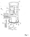
- FIG. 1 The schematic structure of the object struck discrimination system 100 of the embodiment according to the present invention is shown in Fig. 1 .
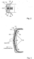
- the sectional structure taken along a line A-A of the vehicle 101 in Fig. 1 is shown in Fig. 2 .
- the vehicle 101 shown in Fig. 1 comprises a front bumper 110, a rear bumper 112, an impact receiving member 120, detection sensors 130, a first absorbing member 140, a second absorbing member 150, a control unit 160, an occupant protection system 170, and a pedestrian protection system 180, and the like.
- the object struck discrimination system 100 is mainly composed of the impact receiving member 120, the detection sensor 130, and the control unit 160.
- the front bumper 110 comprises a bumper frame 110a and a bumper cover 110b made of resin covering a front side of the bumper frame 110a.
- the impact receiving member 120, the detection sensors 130, the first absorbing member 140, and the second absorbing member 150 are disposed.
- the impact receiving member 120 is a member having a high rigidity extending lengthwise along the front bumper 110.
- the impact receiving member 120 composes the "impact receiving portion" or the “impact receiving member” of the present invention.
- the first absorbing member 140 is a member having a low rigidity which is disposed on a rear side of the impact receiving member 120 to absorb impact acting on the impact receiving member 120 during a vehicle collision.
- the detection sensor 130 is a sensor which is disposed between the impact receiving member 120 and the first absorbing member 140 and at a rear side of the impact receiving member 120 and has a function of detecting information about action such as the moving speed or acceleration of the impact receiving member 120 during a vehicle collision.
- the detection sensor 130 composes the "moving speed detection means" or the “acceleration detection means” of the present invention.
- the second absorbing member 150 is a member having a low rigidity which is disposed between the bumper cover 110b and the bumper frame 110a to extend frontward beyond the impact receiving member 120 to absorb the impact acting on the front bumper 110 during a vehicle collision.
- the second absorbing member 150 composes the "absorbing member" of the present invention.
- the control unit 160 comprises a CPU (processing unit) 162 of a known structure, a ROM 164, a RAM 166, and the like and has a function of carrying out respective arithmetic processing and storing processing based on information detected by the detection sensor 130 and a function of outputting control signals to an occupant protection system 170 and a pedestrian protection system 180.
- the control unit 160 is a means having a function of deriving a rate of change in the moving speed per unit time and the acceleration of the impact receiving member 120 based on the information detected by the detection sensor 130 and a function of discriminating an object struck.
- the control unit 160 composes the "object struck discriminating means" of the present invention.
- the control unit 160 also composes the "moving-speed change rate derivation means.
- the occupant protection system 170 is a system having a function of protecting a vehicle occupant during a vehicle collision and may be composed of airbag devices installed in a steering wheel in front of a driver's seat, an instrument ' panel in front of a passenger's seat, a door trim, a seat, and/or a pillar, and a pretensioner for applying predetermined tension to a seat belt.
- the control unit 160 controls the actuation of the occupant protection system 170 in such a manner as to achieve occupant protection by the airbag devices during a vehicle collision.
- the pedestrian protection system 180 is a system having a function of protecting a pedestrian during a vehicle collision and may be composed of a pedestrian protection member which moves toward a pedestrian protection region and the like.
- a structure for lifting a vehicle hood as the pedestrian protection member upward when a vehicle strikes a pedestrian or a structure for making a protection pad member as the pedestrian protection member to act on a pedestrian when a vehicle strikes the pedestrian may be employed to absorb the impact on the pedestrian.
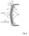
- Fig. 3 shows a state of the vehicle when one of legs of a pedestrian is struck by the front bumper 110
- Fig. 4 shows a state of the vehicle when both legs of a pedestrian are struck by the front bumper 110.
- the behavior of the impact receiving member 120 becomes similar regardless of the position striking the object on the bumper cover 110b.
- the behavior of the impact receiving member 120 is stabilized by the second absorbing member 150 having low rigidity disposed between the bumper cover 110b and the bumper frame 110a.
- control during vehicle collision during the vehicle collision will be described with reference to Figs. 5 through Fig. 9 .
- the “control during vehicle collision” of this embodiment is conducted by the control unit 160 having the aforementioned structure.
- Fig. 5 shows a flow chart of the "control during vehicle collision".
- the "control during vehicle collision" of this embodiment is carried out by sequentially conducting the respective steps of the flow chart shown in Fig. 5 .
- Step S10 in Fig. 5 data are collected in a vehicle collision test previously conducted.
- Step S30 object struck discrimination process A
- object struck discrimination process B object struck discrimination process B
- Step S50 object struck discrimination process B
- step S50 data during actual vehicle collision are compared to the data collected in Step S10 so as to discriminate an object struck.
- Step 30 and Step 50 may be previously selected.
- step 70 in Fig. 5 an occupant and/or a pedestrian are protected based on the result of the discrimination in Step S30 and/or Step S50.
- step S30 is performed without step S50 does not by itself form an embodiment of the invention.
- Step S10 in Fig. 5 is carried out by sequentially conducting the respective steps of the flow chart shown in Fig. 6 .
- Step S12 in Fig. 6 a vehicle collision test is conducted.
- a dummy which is an imitation of a human body is used as the object struck and a vehicle which is an imitation of the vehicle 101 having the structure shown in Fig. 1 is used so as to conduct the test by bringing the vehicle into collision with the dummy.
- the dummy corresponds to the "imitated human body" of the present invention.
- Step S14 in Fig. 6 data of change in moving speed V with time of the impact receiving member 120 during the vehicle collision are measured.
- Step S16 in Fig. 6 the time period elapsing until the moving speed V of the impact receiving member 120 becomes the maximum is set and stored as a reference time Tw.
- the reference time Tw corresponds to the "reference time from the occurrence of the vehicle collision" of the present invention.
- Step S30 in Fig. 5 is carried out by sequentially conducting the respective steps of the flow chart shown in Fig. 7 .
- Step S32 in Fig. 7 measurement by a timer is started at the occurrence of the vehicle collision.
- the time T (elapsed time) at the occurrence of the vehicle collision is set as 0 (zero).
- the occurrence of the vehicle collision is detected by an acceleration sensor capable of detecting acceleration acting on the vehicle in three axial directions (X-axis, Y-axis, Z-axis).
- Step S34 in Fig. 7 the moving speed V of the impact receiving member 120 during the vehicle collision is detected.
- a speed sensor is used as a detection sensor 130.
- a time-rate-of-change S in the moving speed V that is, a rate of change in the moving speed V per unit time is calculated successively and the process proceeds to Step 38. If it is determined that the time-rate-of-change S calculated by Step S36 becomes the maximum until the time T measured by the timer reaches the predetermined reference time Tw ("YES" in Step S38), the object struck is discriminated as a pedestrian (Step S40). If it is determined that it is not the aforementioned case ("NO” in Step S38), the object struck is discriminated as a thing (Step S42). As described above, in the "object struck discrimination process A" and "object struck discrimination process B" as will be described later, the actual discrimination of the object struck is conducted according to the determination of whether the object struck is a person or not.
- Step S50 in Fig. 5 is carried out by sequentially conducting the respective steps of the flow chart shown in Fig. 8 .
- Step S52 in Fig. 8 measurement by a timer is started at the occurrence of the vehicle collision.
- the time T (elapsed time) at the occurrence of the vehicle collision is set as 0 (zero).
- the occurrence of the vehicle collision is detected by an acceleration sensor capable of detecting acceleration acting on the vehicle in three axial directions (X-axis, Y-axis, Z-axis).
- Step S54 in Fig. 8 the acceleration G of the impact receiving member 120 during the vehicle collision is detected.
- an acceleration sensor is used as a detection sensor 130.
- Step S54 If it is determined that the acceleration G detected in Step S54 becomes the maximum until the time T measured by the timer reaches the predetermined reference time Tw ("YES" in Step S56), the object struck is discriminated as a pedestrian (Step S58). If it is determined that it is not the aforementioned case ("NO” in Step S56), the object struck is discriminated as a thing (Step S60).
- Step S70 in Fig. 5 is carried out by sequentially conducting the respective steps of the flow chart shown in Fig. 9 .
- Step S72 in Fig. 9 based on the result in Step S40 or S42 in Fig. 7 or the result in Step S58 or S60 in Fig. 8 , the process proceeds to Step 74 if the object struck is a pedestrian and proceeds to Step 76 if not (the object struck is a thing).
- Step S74 an actuation control signal is outputted to the occupant protection system 170 and the pedestrian protection system 180 to actuate the occupant protection system 170 and the pedestrian protection system 180
- Step S76 an actuation control signal is outputted to the occupant protection system 170 to actuate the occupant protection system 170.
- the airbags of the airbag devices composing the occupant protection system 170 are developed and inflated into the occupant protection region, while the pedestrian protection member composing the pedestrian protection system 180 moves toward the pedestrian protection region. Accordingly, thorough protection of the occupant and the pedestrian during the vehicle collision is achieved.
- the occupant protection system 170 and the pedestrian protection system 180 of this embodiment are actuated to protect the occupant and the pedestrian according to the result of discrimination of the object struck during the vehicle collision and correspond to the "protection system" of the present invention.
- the "protection system” of the present invention may be composed of a combination of the object struck discrimination system 100 with the occupant protection system 170 and the pedestrian protection system 180.
- the discrimination of whether the object struck is a person is made according to the behavior of the impact receiving member 120 during the vehicle collision. Therefore, the accuracy of discrimination of whether the object struck is a person can be increased regardless of the position striking the person on the impact receiving member 120 during the vehicle collision. Since the acceleration detected by the detection sensor 130 is directly used for discrimination of the object struck, a working effect of simplifying a series of processes for discriminating the object struck from the detection of behavior of the impact receiving member 120 can be achieved.
- the result of the discrimination can be used for controlling the pedestrian protection system 180 for providing thorough protection of the person (pedestrian).
- the structure capable of conducting the quick discrimination of the object struck allows relatively slow action of the occupant protection system 170. For example, low-capacity inflators for the airbag devices composing the occupant protection system 170 can be used.
- the impact received by the impact receiving member 120 having high rigidity during the vehicle collision reflects the entirety of the impact receiving member 120. Therefore, the discrimination accuracy for discriminating the object struck can be increased regardless of the position striking the object on the impact receiving portion extending in the vehicle width direction.
- the second absorbing member 150 is disposed to extend frontward beyond the impact receiving member 120, the impact acting on the vehicle body is uniformly applied to the impact receiving member 120 in the dispersed state. Therefore, the vehicle collision can securely reflect to the behavior of the impact receiving member 120, thereby further increasing the discrimination accuracy for discriminating the object struck.
- the present invention is not limited to the aforementioned embodiment and various applications and modifications may be made.
- the following respective embodiments based on the aforementioned embodiment may be carried out.
- the detection sensor 130 may be provided on the bumper cover 110b extending lengthwise along the vehicle width similarly to the impact receiving member 120 so as to detect the behavior of the bumper cover 110b during the vehicle collision in the present invention.
- a front bumper 210 in which no second absorbing member 150 having low rigidity is disposed between the bumper cover and the frame 102 as shown in Fig. 10 may be employed in the present invention.
- the present invention can be adopted to a technology for discriminating an object struck in a collision of a vehicle when driving backward.
- the present invention can be adopted to various vehicles other than automobiles, such as a train, boat and ship.
Landscapes
- Engineering & Computer Science (AREA)
- Mechanical Engineering (AREA)
- Air Bags (AREA)
- Automotive Seat Belt Assembly (AREA)
Description
- The present invention relates to a technology and system for discriminating an object struck by a vehicle such as an automobile.
- Conventionally, various techniques for discriminating whether an object struck by a vehicle is a pedestrian or not have been proposed. For example, disclosed in
Japanese Patent Unexamined Publication No. H10-194158 -
EP 1 350 683claim 1. -
EP 937 612 - The present invention has been made in view of the above demand and it is an object of the present invention to develop an object struck discrimination system for a vehicle which is effective to increase the discrimination accuracy for discriminating an object struck by the vehicle.
- For achieving the object, the present invention is configured. The present invention can be adopted to a technology for discriminating an object struck during a vehicle collision for a wide variety of vehicles such as automobile, train, boat and More specifically, according to the present invention, this object is achieved by an object struck discrimination system according to
claim 1 and a protection system according to claim 5. The dependent claims define preferred or advantageous embodiments of the invention. - According to a background example which, by itself, is not an embodiment of the present invention, for achieving the aforementioned object, an object struck discrimination system for discriminating an object struck by a vehicle is provided. The object struck discrimination system according to this background example is a system to be installed in a vehicle and comprises at least an impact receiving portion, a moving speed detection means, a moving speed change rate derivation means, and an object struck discrimination means.
- The impact receiving portion of this background example extends lengthwise along the vehicle width at a front side or a rear side of a vehicle and has a function of receiving an impact from an object struck. Specific examples of this impact receiving portion include a front bumper cover or a rear bumper cover having low rigidity which is disposed on an outer peripheral portion of the vehicle, and an impact receiving member having high rigidity which is disposed between the bumper cover and a bumper frame. The impact receiving portion moves toward the inside of the vehicle while being deformed by the impact during the vehicle collision.
- The moving speed detection means is a means having a function of detecting the moving speed of the impact receiving portion during a vehicle collision. Typically, the moving speed detection means is composed of a speed detection sensor attached to the impact receiving portion. By the moving speed detection means, the moving speed of the impact receiving portion which moves toward the inside of the vehicle while being deformed during the vehicle collision is detected. Therefore, the moving speed of the impact receiving portion corresponds to the deformation speed of the impact receiving portion.
- The moving speed change rate derivation means is a means having a function of deriving a rate-of-change in the moving speed per unit time of the impact receiving portion based on the information detected by the moving speed detection means. Typically, the moving speed change rate derivation means is composed of a processing unit for conducting arithmetic processing based on signals from the speed detection sensor. By this moving speed change rate derivation means, the rate-of-change in the moving speed per unit time of the impact receiving portion during the vehicle collision is derived.
- The object struck discrimination means is a means having a function of discriminating the object struck based on the rate-of-change in the moving speed per unit time derived by said moving speed change rate derivation means. By the object struck discrimination means, it is possible to discriminate whether the object struck is, for example, a person (a pedestrian) or a thing (a guardrail, an electric pole, or a vehicle). As a specific example of the mode of "discriminating an object struck", a mode of discriminating whether the object struck is a person (a pedestrian) or not based on the rate-of-change in the moving speed per unit time of the impact receiving portion can be employed. In this case, it is structured to determine that the object struck is something other than a person when it is discriminated that the object struck is not a person. That is, actual discrimination of the object struck is conducted according to the discrimination of whether the object struck is a person or not.
- Generally, when a vehicle collides with an object struck, abnormal acceleration which is never generated during normal driving is generated. In this case, there is a marked difference in the rate-of-change in the moving speed per unit time of the impact receiving portion between a case that the object struck is a person and a case that the object struck is a thing. For example, when the vehicle strikes a person, the rate-of-change in the moving speed per unit time of the impact receiving portion is smaller than that in case of a fixed thing or a heavy thing because the mass of the person is significantly smaller than that of the fixed thing such as a guardrail or the heavy thing. Therefore, in the present background example, the system may be structured to discriminate the object struck based on the rate-of-change in the moving speed per unit time of the impact receiving portion among the respective parts of the vehicle, wherein the impact receiving portion receives directly the impact during the vehicle collision at its wide area along the vehicle width. It is preferable to set and store a rate-of-change in the moving speed per unit time of the impact receiving portion in a vehicle collision test or a vehicle collision simulation with an article as an imitation of an object struck and to use the rate-of-change in the moving speed per unit time as the reference for discrimination of an object struck. According to this structure, the object struck is discriminated based on the behavior of the impact receiving portion during the vehicle collision so that the discrimination accuracy for discriminating the object struck can be increased regardless of the position striking the object on the impact receiving portion.
- According to an embodiment of the present invention, the object struck discrimination system is a system to be installed in a vehicle and comprises at least an impact receiving portion, an acceleration detection means, and an object struck discrimination means.
- The impact receiving portion of this embodiment has the same structure as the impact receiving portion described above, that is, it extends lengthwise along the vehicle width at a front side or a rear side of a vehicle and has a function of receiving an impact from an object struck.
- The acceleration detection means of this embodiment is a means having a function of detecting the acceleration of the impact receiving portion during a vehicle collision. Typically, the acceleration detection means is composed of an acceleration detection sensor attached to the impact receiving portion. By the acceleration detection means, the acceleration of the impact receiving portion which moves toward the inside of the vehicle while being deformed during the vehicle collision is detected.
- The object struck discrimination means of this embodiment is a means having a function of discriminating the object struck based on the information detected by the acceleration detection means. By means of the object struck discrimination means, it is possible to discriminate whether the object struck is, for example, a person (a pedestrian) or a thing (a guardrail, an electric pole, or a vehicle). As a specific example of the mode of "discriminating an object struck", a mode of discriminating whether the object struck is a person (a pedestrian) or not based on the acceleration of the impact receiving portion can be employed. In this case, the system is structured to determine that the object struck is something other than person when it is discriminated that the object struck is not a person. That is, actual discrimination of the object struck is conducted according to the discrimination of whether the object struck is a person or not.
- Generally, when a vehicle collides with an object struck, there is a marked difference in the acceleration of the impact receiving portion detected by the acceleration detection means between a case that the object struck is a person and a case that the object struck is a thing. Therefore, in the present embodiment, the system is structured to discriminate the object struck based on the acceleration of the impact receiving portion among the respective parts of the vehicle, wherein the impact receiving portion receives directly the impact during the vehicle collision at its wide area along the vehicle width. It is preferable to set and store acceleration of the impact receiving portion by conducting a vehicle collision test or a vehicle collision simulation with an article as an imitation of an object struck and to use the acceleration as the reference for discrimination of an object struck. According to this structure, the object struck is discriminated based on the behavior of the impact receiving portion during the vehicle collision so that the discrimination accuracy for discriminating the object struck can be increased regardless of the position striking the object on the impact receiving portion. Since the acceleration detected by the acceleration detection means is directly used for discrimination of the object struck, this structure can exhibit a working effect of simplifying a series of processes from the detection of the behavior of the impact receiving portion to the discrimination of the object struck.
- According to an embodiment of the present invention, the object struck discrimination means as described above is structured to discriminate that the object struck is a person when the acceleration detected by the acceleration detection means reaches the maximum until the reference elapsed time has elapsed from the occurrence of the vehicle collision. The reference elapsed time may be defined as a time period elapsing until the rate-of-change in the moving speed per unit time or the acceleration of the impact receiving portion reaches the maximum in a vehicle collision test conducted with an imitated human body as the object struck or may be previously set based on information other than the vehicle collision test (information obtained from, for example, collision simulation). When the acceleration obtained during the actual vehicle collision becomes the maximum until the reference elapsed time has elapsed, the object struck is discriminated as a person. This structure can increase the discrimination accuracy for discriminating that the object struck is a person and achieves the quick discrimination of an object struck within a time period shorter than the reference elapsed time. The result of the discrimination can be used for controlling the protection for a person (pedestrian).
- Further, the reference elapsed time described above may be defined as a time period elapsing between the occurrence of the vehicle collision and a time when the moving speed of an imitated human body reaches the maximum in a vehicle collision test previously conducted with the imitated human body (that is, a doll known as "dummy"). This structure can increase the reliability of discriminating that the object struck is a person by using the reference elapsed time derived from the vehicle collision test.
- According to an embodiment of the present invention, the impact receiving portion described in any one of the above aspects and embodiments is composed of an impact receiving member having high rigidity which extends lengthwise along the vehicle width. According to this structure, since the impact received by the impact receiving member having high rigidity during the vehicle collision acts substantially uniformly on the entire impact receiving member, the discrimination accuracy for discriminating the object struck can be increased regardless of the position striking the object on the impact receiving portion extending in the vehicle width direction.
- Further, if the impact receiving portion is composed of an impact receiving member having high rigidity, the impact receiving portion may have an absorbing member provided on an outer side beyond the impact receiving member. This structure includes an embodiment in which an absorbing member is provided on a front side beyond the impact receiving member when the impact receiving portion is arranged on the front side of the vehicle and an embodiment in which an absorbing member is provided on a rear side beyond the impact receiving member when the impact receiving portion is arranged on the rear side of the vehicle. By the absorbing member, the impact to be received by the vehicle is dispersed so as to act substantially uniformly on the entire impact receiving member. Therefore, the vehicle collision can securely be reflected by the behavior of the impact receiving member, thereby further increasing the discrimination accuracy for discriminating the object struck.
- According to another aspect of the present invention, a protection system is provided, the protection system being a system which is actuated in the event of a vehicle collision to protect a vehicle occupant and/or a pedestrian to ensure the safety of the vehicle occupant and/or the pedestrian. In the present invention, the protection system is actuated according to the result of discrimination of an object struck by an object struck discrimination system according to any one aspect or embodiment of the invention. For example, when it is determined that the object struck is a person (pedestrian), the protection system is actuated to protect the occupant and the pedestrian. The "protection system" includes airbag devices installed in a steering wheel in front of a driver's seat, an instrument panel in front of a passenger's seat, a door trim, a seat, and/or a pillar, and a pretensioner for applying predetermined tension to a seat belt for the purpose of protecting vehicle occupants, and a device for lifting a vehicle hood upward, a device for making a protection pad member or an airbag to act on a pedestrian, and the like for the purpose of protecting the pedestrian.
According to the aforementioned structure, the protection system is actuated with high discrimination accuracy for discriminating an object struck in the event of a vehicle collision, thereby providing thorough protection of the occupant and the pedestrian. - As described above, the present invention can achieve an effective technique of increasing the discrimination accuracy for discriminating an object struck by a structure of discriminating an object struck based on the rate-of-change in the moving speed per unit time or the acceleration during a vehicle collision of an impact receiving portion which extends lengthwise along the vehicle width at the front side or the rear side of the vehicle.
- Hereinafter, embodiments of the present invention will be described with reference to drawings.
-
Fig. 1 shows a schematic structure of an object struck discrimination system of an embodiment according to the present invention. -
Fig. 2 shows a sectional structure taken along a line A-A of a vehicle inFig. 1 . -
Fig. 3 shows a state of the vehicle when one of the legs of a pedestrian is struck by a front bumper. -
Fig. 4 shows a state of the vehicle when both legs of a pedestrian are struck by the front bumper. -
Fig. 5 is a flow chart of "control during vehicle collision". -
Fig. 6 is a flow chart of "data collection process" inFig. 5 . -
Fig. 7 is a flow chart of "object struck discrimination process A" inFig. 5 which, by itself, is not an embodiment of the invention. -
Fig. 8 is a flow chart of "object struck discrimination process B" inFig. 5 . -
Fig. 9 is a flow chart of "occupant/pedestrian protection process" inFig. 5 . -
Fig. 10 shows a sectional structure of a front bumper in another embodiment of the present invention. - First, description will be made with regard to an object struck
discrimination system 100 as an embodiment of the "object struck discrimination system" according to the present invention with reference toFigs. 1 and2 . It should be noted that this embodiment is an object struckdiscrimination system 100 to be installed in avehicle 101, e.g., an automobile. - The schematic structure of the object struck
discrimination system 100 of the embodiment according to the present invention is shown inFig. 1 . The sectional structure taken along a line A-A of thevehicle 101 inFig. 1 is shown inFig. 2 . - The
vehicle 101 shown inFig. 1 comprises afront bumper 110, arear bumper 112, animpact receiving member 120,detection sensors 130, a first absorbingmember 140, a second absorbingmember 150, acontrol unit 160, anoccupant protection system 170, and apedestrian protection system 180, and the like. In this embodiment, the object struckdiscrimination system 100 is mainly composed of theimpact receiving member 120, thedetection sensor 130, and thecontrol unit 160. - As shown in
Fig. 2 , thefront bumper 110 comprises abumper frame 110a and abumper cover 110b made of resin covering a front side of thebumper frame 110a. In an area defined by thebumper frame 110a and thebumper cover 110b, theimpact receiving member 120, thedetection sensors 130, the first absorbingmember 140, and the second absorbingmember 150 are disposed. - The
impact receiving member 120 is a member having a high rigidity extending lengthwise along thefront bumper 110. Theimpact receiving member 120 composes the "impact receiving portion" or the "impact receiving member" of the present invention. The first absorbingmember 140 is a member having a low rigidity which is disposed on a rear side of theimpact receiving member 120 to absorb impact acting on theimpact receiving member 120 during a vehicle collision. Thedetection sensor 130 is a sensor which is disposed between theimpact receiving member 120 and the first absorbingmember 140 and at a rear side of theimpact receiving member 120 and has a function of detecting information about action such as the moving speed or acceleration of theimpact receiving member 120 during a vehicle collision. Thedetection sensor 130 composes the "moving speed detection means" or the "acceleration detection means" of the present invention. The second absorbingmember 150 is a member having a low rigidity which is disposed between thebumper cover 110b and thebumper frame 110a to extend frontward beyond theimpact receiving member 120 to absorb the impact acting on thefront bumper 110 during a vehicle collision. The second absorbingmember 150 composes the "absorbing member" of the present invention. - Reverting to
Fig.1 , thecontrol unit 160 comprises a CPU (processing unit) 162 of a known structure, aROM 164, a RAM 166, and the like and has a function of carrying out respective arithmetic processing and storing processing based on information detected by thedetection sensor 130 and a function of outputting control signals to anoccupant protection system 170 and apedestrian protection system 180. In addition, as will be described later in detail, thecontrol unit 160 is a means having a function of deriving a rate of change in the moving speed per unit time and the acceleration of theimpact receiving member 120 based on the information detected by thedetection sensor 130 and a function of discriminating an object struck. Thecontrol unit 160 composes the "object struck discriminating means" of the present invention. In the background example, thecontrol unit 160 also composes the "moving-speed change rate derivation means. - The
occupant protection system 170 is a system having a function of protecting a vehicle occupant during a vehicle collision and may be composed of airbag devices installed in a steering wheel in front of a driver's seat, an instrument ' panel in front of a passenger's seat, a door trim, a seat, and/or a pillar, and a pretensioner for applying predetermined tension to a seat belt. Thecontrol unit 160 controls the actuation of theoccupant protection system 170 in such a manner as to achieve occupant protection by the airbag devices during a vehicle collision. Thepedestrian protection system 180 is a system having a function of protecting a pedestrian during a vehicle collision and may be composed of a pedestrian protection member which moves toward a pedestrian protection region and the like. As an example, a structure for lifting a vehicle hood as the pedestrian protection member upward when a vehicle strikes a pedestrian or a structure for making a protection pad member as the pedestrian protection member to act on a pedestrian when a vehicle strikes the pedestrian may be employed to absorb the impact on the pedestrian. - The action of the
vehicle 101 during a vehicle collision will now be described with reference toFig. 3 andFig. 4 .Fig. 3 shows a state of the vehicle when one of legs of a pedestrian is struck by thefront bumper 110 andFig. 4 shows a state of the vehicle when both legs of a pedestrian are struck by thefront bumper 110. - It is assumed that one or both of legs of a pedestrian is struck by a central portion - as seen in the lateral direction - of the
front bumper 110. In this case, as shown inFig.3 andFig. 4 , thebumper cover 110b of thefront bumper 110 is deformed by striking the leg or legs of the pedestrian and the second absorbingmember 150 is deformed when absorbing the impact. The impact is dispersed by the second absorbingmember 150 so as to act substantially uniformly on the entireimpact receiving member 120. Theimpact receiving member 120 moves in parallel in a direction of arrows inFigs. 3 andFig. 4 to have similar behavior in both cases ofFig. 3 and theFig. 4 . According to the structure, the behavior of theimpact receiving member 120 becomes similar regardless of the position striking the object on thebumper cover 110b. In this embodiment, the behavior of theimpact receiving member 120 is stabilized by the second absorbingmember 150 having low rigidity disposed between thebumper cover 110b and thebumper frame 110a. - Hereinafter, "control during vehicle collision" during the vehicle collision will be described with reference to
Figs. 5 through Fig. 9 . The "control during vehicle collision" of this embodiment is conducted by thecontrol unit 160 having the aforementioned structure. -
Fig. 5 shows a flow chart of the "control during vehicle collision". The "control during vehicle collision" of this embodiment is carried out by sequentially conducting the respective steps of the flow chart shown inFig. 5 . - First, in "data collection process" designated by Step S10 in
Fig. 5 , data are collected in a vehicle collision test previously conducted. - Then, in "object struck discrimination process A" designated by Step S30 or "object struck discrimination process B" designated by Step S50 in
Fig. 5 , data during actual vehicle collision are compared to the data collected in Step S10 so as to discriminate an object struck. It should be noted that either only one of or both of Step 30 andStep 50 may be previously selected. In "occupant/pedestrian protection process" designated by step 70 inFig. 5 , an occupant and/or a pedestrian are protected based on the result of the discrimination in Step S30 and/or Step S50. The case in which only step S30 is performed without step S50 does not by itself form an embodiment of the invention. - Specifically, the "data collection process" designated by Step S10 in
Fig. 5 is carried out by sequentially conducting the respective steps of the flow chart shown inFig. 6 . - First, by Step S12 in
Fig. 6 , a vehicle collision test is conducted. In the vehicle collision test, a dummy which is an imitation of a human body is used as the object struck and a vehicle which is an imitation of thevehicle 101 having the structure shown inFig. 1 is used so as to conduct the test by bringing the vehicle into collision with the dummy. The dummy corresponds to the "imitated human body" of the present invention. Next, by Step S14 inFig. 6 , data of change in moving speed V with time of theimpact receiving member 120 during the vehicle collision are measured. Then, by Step S16 inFig. 6 , the time period elapsing until the moving speed V of theimpact receiving member 120 becomes the maximum is set and stored as a reference time Tw. The reference time Tw corresponds to the "reference time from the occurrence of the vehicle collision" of the present invention. - Specifically, the "object struck discrimination process A" designated by Step S30 in
Fig. 5 is carried out by sequentially conducting the respective steps of the flow chart shown inFig. 7 . - First, by Step S32 in
Fig. 7 , measurement by a timer is started at the occurrence of the vehicle collision. The time T (elapsed time) at the occurrence of the vehicle collision is set as 0 (zero). It should be noted that the occurrence of the vehicle collision is detected by an acceleration sensor capable of detecting acceleration acting on the vehicle in three axial directions (X-axis, Y-axis, Z-axis). Next, by Step S34 inFig. 7 , the moving speed V of theimpact receiving member 120 during the vehicle collision is detected. To detect the moving speed V, a speed sensor is used as adetection sensor 130. Then, by Step S36 inFig. 7 , a time-rate-of-change S in the moving speed V, that is, a rate of change in the moving speed V per unit time is calculated successively and the process proceeds to Step 38. If it is determined that the time-rate-of-change S calculated by Step S36 becomes the maximum until the time T measured by the timer reaches the predetermined reference time Tw ("YES" in Step S38), the object struck is discriminated as a pedestrian (Step S40). If it is determined that it is not the aforementioned case ("NO" in Step S38), the object struck is discriminated as a thing (Step S42). As described above, in the "object struck discrimination process A" and "object struck discrimination process B" as will be described later, the actual discrimination of the object struck is conducted according to the determination of whether the object struck is a person or not. - Specifically, the "object struck discrimination process B" as designated by Step S50 in
Fig. 5 is carried out by sequentially conducting the respective steps of the flow chart shown inFig. 8 . - First, by Step S52 in
Fig. 8 , measurement by a timer is started at the occurrence of the vehicle collision. The time T (elapsed time) at the occurrence of the vehicle collision is set as 0 (zero). It should be noted that the occurrence of the vehicle collision is detected by an acceleration sensor capable of detecting acceleration acting on the vehicle in three axial directions (X-axis, Y-axis, Z-axis). Next, by Step S54 inFig. 8 , the acceleration G of theimpact receiving member 120 during the vehicle collision is detected. To detect the acceleration G, an acceleration sensor is used as adetection sensor 130. If it is determined that the acceleration G detected in Step S54 becomes the maximum until the time T measured by the timer reaches the predetermined reference time Tw ("YES" in Step S56), the object struck is discriminated as a pedestrian (Step S58). If it is determined that it is not the aforementioned case ("NO" in Step S56), the object struck is discriminated as a thing (Step S60). - Specifically, the "occupant/pedestrian protection process" as designated by Step S70 in
Fig. 5 is carried out by sequentially conducting the respective steps of the flow chart shown inFig. 9 . - In Step S72 in
Fig. 9 , based on the result in Step S40 or S42 inFig. 7 or the result in Step S58 or S60 inFig. 8 , the process proceeds to Step 74 if the object struck is a pedestrian and proceeds to Step 76 if not (the object struck is a thing). In Step S74, an actuation control signal is outputted to theoccupant protection system 170 and thepedestrian protection system 180 to actuate theoccupant protection system 170 and thepedestrian protection system 180, while in Step S76, an actuation control signal is outputted to theoccupant protection system 170 to actuate theoccupant protection system 170. When the actuation signal is received, the airbags of the airbag devices composing theoccupant protection system 170 are developed and inflated into the occupant protection region, while the pedestrian protection member composing thepedestrian protection system 180 moves toward the pedestrian protection region. Accordingly, thorough protection of the occupant and the pedestrian during the vehicle collision is achieved. - As mentioned above, the
occupant protection system 170 and thepedestrian protection system 180 of this embodiment are actuated to protect the occupant and the pedestrian according to the result of discrimination of the object struck during the vehicle collision and correspond to the "protection system" of the present invention. Alternatively, the "protection system" of the present invention may be composed of a combination of the object struckdiscrimination system 100 with theoccupant protection system 170 and thepedestrian protection system 180. - As described above, according to this embodiment, the discrimination of whether the object struck is a person (pedestrian) is made according to the behavior of the
impact receiving member 120 during the vehicle collision. Therefore, the accuracy of discrimination of whether the object struck is a person can be increased regardless of the position striking the person on theimpact receiving member 120 during the vehicle collision. Since the acceleration detected by thedetection sensor 130 is directly used for discrimination of the object struck, a working effect of simplifying a series of processes for discriminating the object struck from the detection of behavior of theimpact receiving member 120 can be achieved. - According to this embodiment, it is possible to conduct the quick discrimination of an object struck within a time period shorter than the reference elapsed time Tw. Since the reference elapsed time Tw is set according to the vehicle collision test previously conducted with a dummy, increased reliability of discriminating that the object struck is a person is obtained. The result of the discrimination can be used for controlling the
pedestrian protection system 180 for providing thorough protection of the person (pedestrian). The structure capable of conducting the quick discrimination of the object struck allows relatively slow action of theoccupant protection system 170. For example, low-capacity inflators for the airbag devices composing theoccupant protection system 170 can be used. In addition, it is possible to control the internal pressure of the airbags and/or the winding amount of a pretensioner according to the severity of the vehicle collision. - Further, according to this embodiment, the impact received by the
impact receiving member 120 having high rigidity during the vehicle collision reflects the entirety of theimpact receiving member 120. Therefore, the discrimination accuracy for discriminating the object struck can be increased regardless of the position striking the object on the impact receiving portion extending in the vehicle width direction. - Further, according to this embodiment, the second absorbing
member 150 is disposed to extend frontward beyond theimpact receiving member 120, the impact acting on the vehicle body is uniformly applied to theimpact receiving member 120 in the dispersed state. Therefore, the vehicle collision can securely reflect to the behavior of theimpact receiving member 120, thereby further increasing the discrimination accuracy for discriminating the object struck. - The present invention is not limited to the aforementioned embodiment and various applications and modifications may be made. For example, the following respective embodiments based on the aforementioned embodiment may be carried out.
- Though the aforementioned embodiment has been described with regard to the structure that the
detection sensor 130 is provided on the rear side of theimpact receiving member 120 to detect the behavior of theimpact receiving member 120 during the vehicle collision, thedetection sensor 130 may be provided on thebumper cover 110b extending lengthwise along the vehicle width similarly to theimpact receiving member 120 so as to detect the behavior of thebumper cover 110b during the vehicle collision in the present invention. - Though the aforementioned embodiment has been described with regard to a case that the structure of the
front bumper 110 as shown inFig. 2 is used, afront bumper 210 in which no second absorbingmember 150 having low rigidity is disposed between the bumper cover and theframe 102 as shown inFig. 10 may be employed in the present invention. - Though the aforementioned embodiment has been described with regard to a case of actually discriminating an object struck based on the discrimination of whether the object struck is a person or not, it can be structured to directly discriminate whether the object struck is a person or a specific object in the present invention.
- Though the aforementioned embodiment has been described with regard to a case of discriminating an object struck in a frontal collision of a vehicle, the present invention can be adopted to a technology for discriminating an object struck in a collision of a vehicle when driving backward.
- Though the aforementioned embodiment has been described with regard to a case of collecting data by conducting a vehicle collision test with a dummy, data may be collected by conducting a collision simulation on the assumption of a situation with a person.
- Though the aforementioned embodiment has been described with regard to the structure of the object struck discrimination system to be installed in an automobile, the present invention can be adopted to various vehicles other than automobiles, such as a train, boat and ship.
Claims (5)
- An object struck discrimination system for discriminating an object struck by a vehicle (101), comprising:an impact receiving portion (120, 140, 150) which extends lengthwise along the vehicle width at a front side or a rear side of a vehicle to receive impact from the object struck; andan acceleration detection means (130) for detecting the acceleration (G) of said impact receiving portion (120, 140, 150) during a vehicle collision;characterized by
an object struck discrimination means (160) for discriminating said object struck based on information detected by said acceleration detection means (130),
wherein the object struck discrimination means (160) discriminates that said object struck is a person when the acceleration (G) detected by said acceleration detection means (130) reaches the maximum until the reference elapsed time (Tw) has elapsed from the occurrence of the vehicle collision. - An object struck discrimination system as claimed in claim 1, wherein said reference elapsed time (Tw) is defined as a time period elapsing between the occurrence of the vehicle collision and a time when the moving speed of an imitated human body reaches the maximum in a vehicle collision test previously conducted with the imitated human body.
- An object struck discrimination system as claimed in any one of claims 1-2, wherein said impact receiving portion is composed of an impact receiving member (120) having high rigidity which extends lengthwise along the vehicle width.
- An object struck discrimination system as claimed in claim 3, wherein said impact receiving portion has an absorbing member (150) provided on an outer side beyond said impact receiving member (120).
- A protection system which is actuated in the event of a vehicle collision to protect a vehicle occupant or a pedestrian, wherein said protection system is actuated according to the result of discrimination of an object struck by an object struck discrimination system (100) as claimed in any one of claims 1-4.
Applications Claiming Priority (1)
| Application Number | Priority Date | Filing Date | Title |
|---|---|---|---|
| JP2004273425A JP4376743B2 (en) | 2004-09-21 | 2004-09-21 | Collision detection device, protection device |
Publications (2)
| Publication Number | Publication Date |
|---|---|
| EP1637405A1 EP1637405A1 (en) | 2006-03-22 |
| EP1637405B1 true EP1637405B1 (en) | 2008-02-27 |
Family
ID=35453550
Family Applications (1)
| Application Number | Title | Priority Date | Filing Date |
|---|---|---|---|
| EP05018155A Expired - Fee Related EP1637405B1 (en) | 2004-09-21 | 2005-08-22 | Object struck discrimination system and protection system |
Country Status (4)
| Country | Link |
|---|---|
| US (1) | US7881843B2 (en) |
| EP (1) | EP1637405B1 (en) |
| JP (1) | JP4376743B2 (en) |
| DE (1) | DE602005004970T2 (en) |
Cited By (1)
| Publication number | Priority date | Publication date | Assignee | Title |
|---|---|---|---|---|
| CN104943640A (en) * | 2014-03-26 | 2015-09-30 | 福特全球技术公司 | Pedestrian protection sensing system for vehicle having metal bumper |
Families Citing this family (21)
| Publication number | Priority date | Publication date | Assignee | Title |
|---|---|---|---|---|
| DE10346213A1 (en) * | 2003-10-06 | 2005-04-21 | Bosch Gmbh Robert | Regulating load condition of energy storage device for vehicle with hybrid drive involves regulating state of charge of energy storage device depending on vehicle's speed of travel |
| DE102004053431A1 (en) * | 2004-11-05 | 2006-05-11 | Bayerische Motoren Werke Ag | Device for triggering passive occupant safety measures |
| US7552792B2 (en) * | 2005-03-07 | 2009-06-30 | Delphi Technologies, Inc. | Vehicle pedestrian impact sensor with proximity arming |
| JP2007314055A (en) * | 2006-05-26 | 2007-12-06 | Denso Corp | Collision object discriminating device for vehicle |
| JP5077639B2 (en) * | 2006-12-11 | 2012-11-21 | 株式会社デンソー | Pedestrian collision detection device and pedestrian protection system |
| JP4264844B2 (en) * | 2007-06-21 | 2009-05-20 | 株式会社デンソー | Vehicle collision detection device |
| JP5302643B2 (en) * | 2008-12-02 | 2013-10-02 | 株式会社デンソー | Collision detection device and collision detection method |
| KR101033790B1 (en) * | 2008-12-04 | 2011-05-13 | 기아자동차주식회사 | External air-bag system for a vehicle |
| US8412404B2 (en) * | 2009-03-06 | 2013-04-02 | Ford Global Technologies, Llc | Crash sensor system and method for a vehicle |
| KR20110048204A (en) * | 2009-11-02 | 2011-05-11 | 현대자동차주식회사 | Airbag control system |
| EP2653360B1 (en) * | 2012-04-16 | 2017-11-01 | Volvo Car Corporation | Large animal vehicle collision safety apparatus and method |
| KR101438966B1 (en) * | 2012-12-26 | 2014-09-15 | 현대자동차주식회사 | Radiator grill for relieving injury of pedestrian |
| US8973957B2 (en) * | 2013-04-22 | 2015-03-10 | Shape Corp. | Bumper energy absorber with sensor and configured lobes |
| US9586555B2 (en) | 2013-12-31 | 2017-03-07 | Tk Holdings Inc. | Active pedestrian protection system |
| DE112014006091T5 (en) * | 2013-12-30 | 2016-11-03 | Tk Holdings Inc. | Active knee protection system |
| AT515500A1 (en) * | 2014-03-12 | 2015-09-15 | Siemens Ag Oesterreich | Device and method for obstacle detection in rail vehicles |
| US9067553B1 (en) * | 2014-06-06 | 2015-06-30 | Ford Global Technologies, Llc | Vehicle fascia integrated pushers |
| CN107745744A (en) * | 2017-10-17 | 2018-03-02 | 黄河交通学院 | A kind of lightweight longitudinal beam of automobile frame structure |
| CN110667506B (en) * | 2019-10-18 | 2022-01-04 | 广州斯沃德科技有限公司 | Collision recognition method, device, equipment and storage medium |
| CN115195658B (en) * | 2022-07-14 | 2023-05-16 | 浙江极氪智能科技有限公司 | Active crumple system, method, vehicle and storage medium |
| CN117029936B (en) * | 2023-10-10 | 2024-01-23 | 武汉能钠智能装备技术股份有限公司 | Abnormal signal real-time interception device, system and method |
Family Cites Families (16)
| Publication number | Priority date | Publication date | Assignee | Title |
|---|---|---|---|---|
| JP2920284B2 (en) | 1995-02-24 | 1999-07-19 | トヨタ自動車株式会社 | Pedestrian protection device |
| JP3785713B2 (en) | 1997-01-08 | 2006-06-14 | 日産自動車株式会社 | Hood flip-up device |
| US6561301B1 (en) * | 1998-02-24 | 2003-05-13 | Kabushiki Kaisha Toyota Chuo Kenkyusho | Collision discriminating apparatus for vehicles |
| EP0937612A3 (en) * | 1998-02-24 | 2000-03-15 | Kabushiki Kaisha Toyota Chuo Kenkyusho | A collision discriminating apparatus for vehicles using detecting means in the front bumper |
| GB2336704A (en) | 1998-04-24 | 1999-10-27 | Jaguar Cars | Pedestrian impact sensor system |
| US6516278B1 (en) * | 1999-09-16 | 2003-02-04 | Honda Giken Kogyo Kabushiki Kaisha | Vehicle hood operating system |
| DE10030465A1 (en) * | 2000-06-21 | 2002-01-03 | Bosch Gmbh Robert | Method and device for detecting a pedestrian impact |
| US6510914B2 (en) * | 2000-07-26 | 2003-01-28 | Honda Giken Kogyo Kabushiki Kaisha | Obstruction inference apparatus for vehicle |
| GB0113525D0 (en) * | 2001-06-02 | 2001-07-25 | Autoliv Dev | Improvemnts in or relating to a detector for a safety arrangement |
| DE10134331C1 (en) | 2001-07-14 | 2002-10-10 | Bosch Gmbh Robert | Controlling triggering of passive safety system involves detecting impact speed from time difference between start of impact, transition of acceleration from low to higher acceleration |
| JP4685289B2 (en) | 2001-09-03 | 2011-05-18 | 本田技研工業株式会社 | Collision detection system |
| JP4306229B2 (en) | 2002-04-03 | 2009-07-29 | タカタ株式会社 | Collision detection device and safety device |
| JP4206741B2 (en) | 2002-04-03 | 2009-01-14 | タカタ株式会社 | Collision detection device and safety device |
| CA2433598C (en) * | 2002-06-25 | 2009-07-28 | Honda Giken Kogyo Kabushiki Kaisha | Collision determination system |
| US6832145B2 (en) * | 2002-09-24 | 2004-12-14 | Denso Corporation | Pedestrian collision protection system and collision site detecting apparatus for use in vehicle |
| JP4000519B2 (en) | 2002-12-20 | 2007-10-31 | 株式会社デンソー | Vehicle collision object discrimination device |
-
2004
- 2004-09-21 JP JP2004273425A patent/JP4376743B2/en not_active Expired - Fee Related
-
2005
- 2005-08-22 EP EP05018155A patent/EP1637405B1/en not_active Expired - Fee Related
- 2005-08-22 DE DE602005004970T patent/DE602005004970T2/en active Active
- 2005-09-02 US US11/219,398 patent/US7881843B2/en not_active Expired - Fee Related
Cited By (1)
| Publication number | Priority date | Publication date | Assignee | Title |
|---|---|---|---|---|
| CN104943640A (en) * | 2014-03-26 | 2015-09-30 | 福特全球技术公司 | Pedestrian protection sensing system for vehicle having metal bumper |
Also Published As
| Publication number | Publication date |
|---|---|
| JP2006088755A (en) | 2006-04-06 |
| DE602005004970D1 (en) | 2008-04-10 |
| US7881843B2 (en) | 2011-02-01 |
| EP1637405A1 (en) | 2006-03-22 |
| DE602005004970T2 (en) | 2009-02-26 |
| JP4376743B2 (en) | 2009-12-02 |
| US20060064220A1 (en) | 2006-03-23 |
Similar Documents
| Publication | Publication Date | Title |
|---|---|---|
| EP1637405B1 (en) | Object struck discrimination system and protection system | |
| EP1637406B1 (en) | Object struck discrimination system and protection system | |
| US7543677B2 (en) | Object detection system, protection system, and vehicle | |
| US5673932A (en) | Procedure and device for protecting vehicle occupants | |
| EP0987151B1 (en) | Control apparatus of safety device for crew | |
| US7905314B2 (en) | Pedestrian detecting system | |
| US7484756B2 (en) | Vehicle side impact crash detection for deployment of curtain and side airbags | |
| JP3436185B2 (en) | Activation control device for occupant protection device | |
| US7890263B2 (en) | System and method for sensing and deployment control supervision of a safety device | |
| US7422086B2 (en) | Vehicle impact sensor using both accelerometer and pressure sensing for side impact detection | |
| JPH11310095A (en) | Vehicular collision discriminative device | |
| EP1026052B1 (en) | Activating control of a vehicle passenger restraint system | |
| JP2008529884A (en) | Validity of side impact using lateral velocity | |
| JP2877145B2 (en) | Control device for occupant protection device | |
| JP3695351B2 (en) | Occupant protection device starter | |
| US20030078715A1 (en) | Arrangement having a damper element, motor vehicle with such an arrangement and method for operating such an arrangement or such a motor vehicle | |
| US5394328A (en) | Method for activating an occupanct restraint in a vehicle | |
| Friedewald | Design methods for adjusting the side airbag sensor and the car body | |
| JP2964796B2 (en) | Control device for occupant restraint system | |
| KR100551821B1 (en) | Method for controlling automobile airbag | |
| KR20060033824A (en) | Air-bag's control method | |
| KR20060033825A (en) | Air-bag's control method | |
| GB2291994A (en) | Motor vehicle safety arrangement | |
| KR20070033763A (en) | Airbag device | |
| KR20060016409A (en) | Air-bag's control method |
Legal Events
| Date | Code | Title | Description |
|---|---|---|---|
| PUAI | Public reference made under article 153(3) epc to a published international application that has entered the european phase |
Free format text: ORIGINAL CODE: 0009012 |
|
| AK | Designated contracting states |
Kind code of ref document: A1 Designated state(s): AT BE BG CH CY CZ DE DK EE ES FI FR GB GR HU IE IS IT LI LT LU LV MC NL PL PT RO SE SI SK TR |
|
| AX | Request for extension of the european patent |
Extension state: AL BA HR MK YU |
|
| 17P | Request for examination filed |
Effective date: 20060728 |
|
| 17Q | First examination report despatched |
Effective date: 20060904 |
|
| AKX | Designation fees paid |
Designated state(s): DE FR GB SE |
|
| GRAP | Despatch of communication of intention to grant a patent |
Free format text: ORIGINAL CODE: EPIDOSNIGR1 |
|
| RIC1 | Information provided on ipc code assigned before grant |
Ipc: B60R 21/013 20060101AFI20070813BHEP |
|
| GRAS | Grant fee paid |
Free format text: ORIGINAL CODE: EPIDOSNIGR3 |
|
| GRAA | (expected) grant |
Free format text: ORIGINAL CODE: 0009210 |
|
| RIN1 | Information on inventor provided before grant (corrected) |
Inventor name: MURAKAMI, DAISUKE Inventor name: AOKI, HIROSHI |
|
| AK | Designated contracting states |
Kind code of ref document: B1 Designated state(s): DE FR GB SE |
|
| REG | Reference to a national code |
Ref country code: GB Ref legal event code: FG4D |
|
| REF | Corresponds to: |
Ref document number: 602005004970 Country of ref document: DE Date of ref document: 20080410 Kind code of ref document: P |
|
| PG25 | Lapsed in a contracting state [announced via postgrant information from national office to epo] |
Ref country code: SE Free format text: LAPSE BECAUSE OF FAILURE TO SUBMIT A TRANSLATION OF THE DESCRIPTION OR TO PAY THE FEE WITHIN THE PRESCRIBED TIME-LIMIT Effective date: 20080527 |
|
| EN | Fr: translation not filed | ||
| PLBE | No opposition filed within time limit |
Free format text: ORIGINAL CODE: 0009261 |
|
| STAA | Information on the status of an ep patent application or granted ep patent |
Free format text: STATUS: NO OPPOSITION FILED WITHIN TIME LIMIT |
|
| 26N | No opposition filed |
Effective date: 20081128 |
|
| PG25 | Lapsed in a contracting state [announced via postgrant information from national office to epo] |
Ref country code: FR Free format text: LAPSE BECAUSE OF FAILURE TO SUBMIT A TRANSLATION OF THE DESCRIPTION OR TO PAY THE FEE WITHIN THE PRESCRIBED TIME-LIMIT Effective date: 20081219 |
|
| PGFP | Annual fee paid to national office [announced via postgrant information from national office to epo] |
Ref country code: GB Payment date: 20120822 Year of fee payment: 8 |
|
| PGFP | Annual fee paid to national office [announced via postgrant information from national office to epo] |
Ref country code: DE Payment date: 20130814 Year of fee payment: 9 |
|
| GBPC | Gb: european patent ceased through non-payment of renewal fee |
Effective date: 20130822 |
|
| PG25 | Lapsed in a contracting state [announced via postgrant information from national office to epo] |
Ref country code: GB Free format text: LAPSE BECAUSE OF NON-PAYMENT OF DUE FEES Effective date: 20130822 |
|
| REG | Reference to a national code |
Ref country code: DE Ref legal event code: R119 Ref document number: 602005004970 Country of ref document: DE |
|
| REG | Reference to a national code |
Ref country code: DE Ref legal event code: R119 Ref document number: 602005004970 Country of ref document: DE Effective date: 20150303 |
|
| PG25 | Lapsed in a contracting state [announced via postgrant information from national office to epo] |
Ref country code: DE Free format text: LAPSE BECAUSE OF NON-PAYMENT OF DUE FEES Effective date: 20150303 |