EP1634766B1 - A combined ramp and vehicle chocking construction - Google Patents
A combined ramp and vehicle chocking construction Download PDFInfo
- Publication number
- EP1634766B1 EP1634766B1 EP05445050A EP05445050A EP1634766B1 EP 1634766 B1 EP1634766 B1 EP 1634766B1 EP 05445050 A EP05445050 A EP 05445050A EP 05445050 A EP05445050 A EP 05445050A EP 1634766 B1 EP1634766 B1 EP 1634766B1
- Authority
- EP
- European Patent Office
- Prior art keywords
- units
- ramp
- vehicle
- chocking
- chocking construction
- Prior art date
- Legal status (The legal status is an assumption and is not a legal conclusion. Google has not performed a legal analysis and makes no representation as to the accuracy of the status listed.)
- Active
Links
- 238000010276 construction Methods 0.000 title claims description 52
- 230000001154 acute effect Effects 0.000 description 2
- 230000003319 supportive effect Effects 0.000 description 2
Images

Classifications
-
- B—PERFORMING OPERATIONS; TRANSPORTING
- B66—HOISTING; LIFTING; HAULING
- B66F—HOISTING, LIFTING, HAULING OR PUSHING, NOT OTHERWISE PROVIDED FOR, e.g. DEVICES WHICH APPLY A LIFTING OR PUSHING FORCE DIRECTLY TO THE SURFACE OF A LOAD
- B66F7/00—Lifting frames, e.g. for lifting vehicles; Platform lifts
- B66F7/24—Lifting frames, e.g. for lifting vehicles; Platform lifts for raising or lowering vehicles by their own power
- B66F7/243—Ramps
-
- B—PERFORMING OPERATIONS; TRANSPORTING
- B60—VEHICLES IN GENERAL
- B60P—VEHICLES ADAPTED FOR LOAD TRANSPORTATION OR TO TRANSPORT, TO CARRY, OR TO COMPRISE SPECIAL LOADS OR OBJECTS
- B60P3/00—Vehicles adapted to transport, to carry or to comprise special loads or objects
- B60P3/06—Vehicles adapted to transport, to carry or to comprise special loads or objects for carrying vehicles
- B60P3/07—Vehicles adapted to transport, to carry or to comprise special loads or objects for carrying vehicles for carrying road vehicles
- B60P3/073—Vehicle retainers
- B60P3/075—Vehicle retainers for wheels, hubs, or axle shafts
- B60P3/077—Wheel cradles, chocks, or wells
-
- B—PERFORMING OPERATIONS; TRANSPORTING
- B60—VEHICLES IN GENERAL
- B60S—SERVICING, CLEANING, REPAIRING, SUPPORTING, LIFTING, OR MANOEUVRING OF VEHICLES, NOT OTHERWISE PROVIDED FOR
- B60S5/00—Servicing, maintaining, repairing, or refitting of vehicles
Definitions
- the present invention relates to a combined ramp and vehicle chocking construction for four-wheeled vehicle which can be adjusted to a first position in which the construction forms a ramp and a second position in which the construction forms four vehicle chock, and which includes four units that are arranged sequentially two by two in the longitudinal direction of the vehicle.
- Car-O-Liner AB markets a vehicle straightening bench under the trade name Mark 6 which comprises a combined ramp and vehicle chocking construction that includes rear articulated units and front moveable units.
- a vehicle drives up onto the construction when the construction is in its first position, i.e. the ramp position.
- the front wheels of the vehicle reach the front moveable units the wheels accompany the forward movement of said units until the vehicle is stopped, when its rear wheels have reached the rear articulated units.
- the vehicle is raised with the aid of an elevator or lift, whereafter the units are adjusted to said second position, i.e. the vehicle chocking position. This position is reached by turning the front moveable units in a known manner, while folding together the rear articulated units.
- the second position is extremely low.
- the vehicle When the vehicle stands on the units in the vehicle chocking position of the construction, the vehicle is extremely close to the floor on which the construction stands. If the vehicle is to be secured to a frame on the straightening bench for complex repair work, it is necessary to fit bench parts to the frame to which the vehicle is secured. If the underside of the vehicle is to be repaired with the vehicle standing on the units in the vehicle chocking position, it must be ensured that access can be obtained. Regardless of the application concerned, the construction presents an uncomfortable working position to the user.
- Another problem is that a front-wheel-drive vehicle is forced to reverse onto the construction, since the front moveable units do not allow driving of the vehicle on solely those wheels that are driven up onto the units.
- each of the units is an elongate structure and pivotal or rotatable about an axis that is perpendicular to the longitudinal direction of the vehicle.
- Each unit is also adapted so as to be generally straight in said first position and generally angled or non-straight in said second position as a result of being rotated about its articulated joint.
- the units preferably comprise two parts, wherein when seen from one side, the units will have generally the form of an inverse V, preferably a relatively acute V in the second position. Alternatively, the units are angled through 180 degrees in the second position.
- the present invention enables a second position to be achieved, where the construction provides for vehicle chocking elements on which the vehicle is high above the underlying supportive surface on which the construction stands, therewith facilitating all work to be carried out on the vehicle.
- the units which are generally straight in the first position in which the construction forms a ramp, are preferably horizontal and locked two and two together in the longitudinal direction. In this case, the units are immovable when a vehicle is driven onto the ramp, wherewith it is unessential whether the vehicle is a front-wheel-drive or a rear-wheel-drive.
- the inventive construction allows the vehicle to continue forwards and drive off the ramp in a forward direction, instead of being forced to reverse down the ramp.
- the units will conveniently include spring devices which generally take up the forces with which the weights of the units act in switching from the second position to the first position. Thus, only a relatively small force is required to switch the positions of the construction.
- a combined ramp and chocking construction 1 for a four-wheel-drive vehicle is shown in figures 1 - 4 .
- the construction can be adjusted to a first, downwardly lowered position in which the construction forms a ramp, as shown in figure 1 , and a second upwardly raised position in which the construction provides four so-called chocks as shown in figure 2 .
- the first, downwardly lowered position will be referred to as a ramp position in the following text, whereas the raised second position will be referred to as a vehicle chocking position.
- the construction comprises four units 2 which are arranged sequentially two by two in the longitudinal direction 3 of a vehicle situated on the construction.
- Each unit 2 is elongate and comprises two preferably generally hollow elements 2a-b, which are joined together by means of an articulating joint 4 so as to enable the units to pivot relative to each other about an axis 5 that extends at right angles to the longitudinal direction 3.
- each unit 2 is arranged to be generally straight and horizontal on a supportive surface in the ramp position, by virtue of rotation about its joints 4, and generally angled or non-straight in the vehicle chocking position.
- each unit 2 When seen from one side, each unit 2 will generally have the form of an inverse V relative to the longitudinal direction 3 in the chocking position, where the two elements define an acute angle ⁇ which is smaller than about 30 degrees. The angle is chosen to obtain a significant height of the units 2 in the chocking position on the one hand, and so that the weight of a chocked vehicle will not act at an excessively large angle on the long axis of the elements 2a-b on the other hand.
- each unit 2 can be angled at 180 degrees in the chocking position, i.e. the angle ⁇ is 0 degrees.
- Each unit 2 also includes a spring device 6, preferably in the form of a torsion spring that is tensioned so that its spring force will generally support the force with which the weight of the unit acts when shifting from the chocking position to the ramp position. In this way, only a minimum force is required to lift the units from the ramp position to the chocking position.
- a spring device 6 preferably in the form of a torsion spring that is tensioned so that its spring force will generally support the force with which the weight of the unit acts when shifting from the chocking position to the ramp position. In this way, only a minimum force is required to lift the units from the ramp position to the chocking position.
- FIG. 4c An enlarged view of the torsion spring 6 is shown in figures 3b and 4c .
- Each unit 2 includes latching means for latching the unit in the vehicle chocking position.
- a latch may include two stays or struts 7 on respective sides of the unit 2, these struts being pivotally secured to one, 2a, of the elements 2a-b.
- the stays or struts 7 can be manoeuvred by means of a lever or the like that runs in slots located on respective sides of the second, 2b, of the elements 2a-b of the unit. These slots are preferably angled so that when the unit 2 is switched from the ramp position to the chocking position, the lever 8 will first run in a first part 9a of respective slots and thereafter in a second part 9b of said slots.
- the slot parts 9a-b define angles in mutually different directions with the long axis of the second element 2b, so as to enable the unit 2 to be moved readily from the ramp position to the vehicle chocking position and locked in this latter position by pulling up the lever.
- the means for latching the vehicle chocking position may have a different design to that shown.
- each unit may be provided with latching means for latching the unit in the ramp position.
- the combined ramp and chocking construction also includes securing devices 10 for securing the units 2 sequentially, two by two, in the longitudinal direction 3.
- the securing devices may consist of hooks pivotally connected to one of the two sequentially arranged units 2. These hooks can be caused to engage pins or eyes mounted on the other of said two sequentially arranged units 2.
- the construction includes two devices 11 formed by the units sideways in relation to the longitudinal direction 3 for a vehicle drive-on ramp in the ramp position of the construction. It will be understood that the remaining two units 2 may also be equipped with devices 11 which form a vehicle drive-on ramp in the ramp position of the construction, so that a vehicle is able to drive onto the ramp from any chosen direction. It will be noted that the devices 11 are not shown in figure 2 .
- Each unit 2 will conveniently include sprung wheels 12 that cause the unit 2 to roll in the longitudinal direction 3 in a non-loaded state in the chocking position of the construction, i.e. in a position in which no weight is supplied to the unit and which is held firmly against the underlying surface in a loaded state, i.e. when a vehicle is "chocked" on the construction, wherewith part of the weight of the vehicle loads the unit.
- the wheels will preferably be sprung with the aid of leaf springs 13 or the like that function to press the wheel axels down so that the wheels will be free to rotate when no load acts on the unit, this being shown in figures 4a-b.
- the springs When load acts on the units, the springs will be pressed back and the wheel axles pressed upwards, so that the wheels will no longer be free to rotate.
- An enlarged view of the leaf spring 13 is shown in figure 3c and 4b .
- a vehicle is chocked in the following way.
- the vehicle is driven up onto the units 2 via the vehicle drive-on ramp 11.
- An elevator or lift is caused to lift the vehicle to a height that is greater than the height of the combined ramp and chocking construction in the chocking position of the construction.
- Securing devices 10 that secure the units sequentially, two by two, in the longitudinal direction 3 are released.
- Each unit 2 is then switched to the vehicle chocking position, by pulling up the levers 8 of respective units 2.
- the units 2 are adjusted roughly in the longitudinal direction 3 so that the respective upper V-shaped surfaces 14 will be located roughly beneath respective wheels of the vehicle, whereafter the vehicle is lowered by means of the lift. Because the units 2 are provided with said sprung wheels 12, the upper V-shaped surfaces 14 of the units 2 will co-act with the wheels of the vehicle when the vehicle is lowered, so that the units will be adjusted automatically to their correct positions.
Landscapes
- Engineering & Computer Science (AREA)
- Mechanical Engineering (AREA)
- Geology (AREA)
- Structural Engineering (AREA)
- Life Sciences & Earth Sciences (AREA)
- Health & Medical Sciences (AREA)
- Public Health (AREA)
- Transportation (AREA)
- Body Structure For Vehicles (AREA)
- Vehicle Body Suspensions (AREA)
- Road Paving Structures (AREA)
- Braking Arrangements (AREA)
- Vehicle Cleaning, Maintenance, Repair, Refitting, And Outriggers (AREA)
- Heat Treatment Of Strip Materials And Filament Materials (AREA)
- Bridges Or Land Bridges (AREA)
- Handcart (AREA)
Abstract
Description
- The present invention relates to a combined ramp and vehicle chocking construction for four-wheeled vehicle which can be adjusted to a first position in which the construction forms a ramp and a second position in which the construction forms four vehicle chock, and which includes four units that are arranged sequentially two by two in the longitudinal direction of the vehicle.
- Such a combined ramp and vehicle chocking construction is earlier known. Car-O-Liner AB markets a vehicle straightening bench under the trade name Mark 6 which comprises a combined ramp and vehicle chocking construction that includes rear articulated units and front moveable units. A vehicle drives up onto the construction when the construction is in its first position, i.e. the ramp position. When the front wheels of the vehicle reach the front moveable units the wheels accompany the forward movement of said units until the vehicle is stopped, when its rear wheels have reached the rear articulated units. The vehicle is raised with the aid of an elevator or lift, whereafter the units are adjusted to said second position, i.e. the vehicle chocking position. This position is reached by turning the front moveable units in a known manner, while folding together the rear articulated units.
- A further ramp is known from
US 6135420 . - One of the problems encountered with this known combined ramp and vehicle chocking construction is that the second position is extremely low. When the vehicle stands on the units in the vehicle chocking position of the construction, the vehicle is extremely close to the floor on which the construction stands. If the vehicle is to be secured to a frame on the straightening bench for complex repair work, it is necessary to fit bench parts to the frame to which the vehicle is secured. If the underside of the vehicle is to be repaired with the vehicle standing on the units in the vehicle chocking position, it must be ensured that access can be obtained. Regardless of the application concerned, the construction presents an uncomfortable working position to the user.
- Another problem is that a front-wheel-drive vehicle is forced to reverse onto the construction, since the front moveable units do not allow driving of the vehicle on solely those wheels that are driven up onto the units.
- These problems are resolved with a combined ramp and vehicle chocking construction of the kind described in the introduction, where each of the units is an elongate structure and pivotal or rotatable about an axis that is perpendicular to the longitudinal direction of the vehicle. Each unit is also adapted so as to be generally straight in said first position and generally angled or non-straight in said second position as a result of being rotated about its articulated joint.
- The units preferably comprise two parts, wherein when seen from one side, the units will have generally the form of an inverse V, preferably a relatively acute V in the second position. Alternatively, the units are angled through 180 degrees in the second position.
- The present invention enables a second position to be achieved, where the construction provides for vehicle chocking elements on which the vehicle is high above the underlying supportive surface on which the construction stands, therewith facilitating all work to be carried out on the vehicle. The units, which are generally straight in the first position in which the construction forms a ramp, are preferably horizontal and locked two and two together in the longitudinal direction. In this case, the units are immovable when a vehicle is driven onto the ramp, wherewith it is unessential whether the vehicle is a front-wheel-drive or a rear-wheel-drive. Moreover, the inventive construction allows the vehicle to continue forwards and drive off the ramp in a forward direction, instead of being forced to reverse down the ramp.
- The units will conveniently include spring devices which generally take up the forces with which the weights of the units act in switching from the second position to the first position. Thus, only a relatively small force is required to switch the positions of the construction.
- The invention will be described in more detail with reference to
figures 1 - 4 , which are solely meant to illustrate the invention and shall not therefore be considered to limit the scope of the invention. -
Figures 1 - 2 are diagrammatic views of a combined ramp and vehicle chocking construction in the downwardly swung ramp position and the upwardly swung vehicle chocking position respectively. -
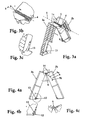
Figure 3a is a diagrammatic view of a unit included in the combined ramp and vehicle chocking construction infigures 1 - 2 , where parts have been omitted for the sake of illustration. -
Figures 3b and 3c are enlarged views of selected parts offigure 3a . -
Figure 4a is a section view of the unit shown infigure 3a, and figures 4b and 4c are enlarged views of chosen parts offigure 4a . - A combined ramp and chocking construction 1 for a four-wheel-drive vehicle is shown in
figures 1 - 4 . The construction can be adjusted to a first, downwardly lowered position in which the construction forms a ramp, as shown infigure 1 , and a second upwardly raised position in which the construction provides four so-called chocks as shown infigure 2 . The first, downwardly lowered position will be referred to as a ramp position in the following text, whereas the raised second position will be referred to as a vehicle chocking position. - The construction comprises four
units 2 which are arranged sequentially two by two in thelongitudinal direction 3 of a vehicle situated on the construction. Eachunit 2 is elongate and comprises two preferably generallyhollow elements 2a-b, which are joined together by means of anarticulating joint 4 so as to enable the units to pivot relative to each other about anaxis 5 that extends at right angles to thelongitudinal direction 3. - According to the present invention, each
unit 2 is arranged to be generally straight and horizontal on a supportive surface in the ramp position, by virtue of rotation about itsjoints 4, and generally angled or non-straight in the vehicle chocking position. When seen from one side, eachunit 2 will generally have the form of an inverse V relative to thelongitudinal direction 3 in the chocking position, where the two elements define an acute angle α which is smaller than about 30 degrees. The angle is chosen to obtain a significant height of theunits 2 in the chocking position on the one hand, and so that the weight of a chocked vehicle will not act at an excessively large angle on the long axis of theelements 2a-b on the other hand. Alternatively, eachunit 2 can be angled at 180 degrees in the chocking position, i.e. the angle α is 0 degrees. - Each
unit 2 also includes aspring device 6, preferably in the form of a torsion spring that is tensioned so that its spring force will generally support the force with which the weight of the unit acts when shifting from the chocking position to the ramp position. In this way, only a minimum force is required to lift the units from the ramp position to the chocking position. An enlarged view of thetorsion spring 6 is shown infigures 3b and 4c . - It will be understood by the person skilled in this art that other spring devices can be used to obtain a technically equivalent function.
- Each
unit 2 includes latching means for latching the unit in the vehicle chocking position. Such a latch may include two stays or struts 7 on respective sides of theunit 2, these struts being pivotally secured to one, 2a, of theelements 2a-b. The stays or struts 7 can be manoeuvred by means of a lever or the like that runs in slots located on respective sides of the second, 2b, of theelements 2a-b of the unit. These slots are preferably angled so that when theunit 2 is switched from the ramp position to the chocking position, thelever 8 will first run in afirst part 9a of respective slots and thereafter in asecond part 9b of said slots. Theslot parts 9a-b define angles in mutually different directions with the long axis of thesecond element 2b, so as to enable theunit 2 to be moved readily from the ramp position to the vehicle chocking position and locked in this latter position by pulling up the lever. It will, of course, be apparent that the means for latching the vehicle chocking position may have a different design to that shown. Moreover, each unit may be provided with latching means for latching the unit in the ramp position. - The combined ramp and chocking construction also includes securing
devices 10 for securing theunits 2 sequentially, two by two, in thelongitudinal direction 3. For each pair of units to be secured to one another, the securing devices may consist of hooks pivotally connected to one of the two sequentially arrangedunits 2. These hooks can be caused to engage pins or eyes mounted on the other of said two sequentially arrangedunits 2. - In order to enable a vehicle to drive up the construction in its ramp position, the construction includes two
devices 11 formed by the units sideways in relation to thelongitudinal direction 3 for a vehicle drive-on ramp in the ramp position of the construction. It will be understood that the remaining twounits 2 may also be equipped withdevices 11 which form a vehicle drive-on ramp in the ramp position of the construction, so that a vehicle is able to drive onto the ramp from any chosen direction. It will be noted that thedevices 11 are not shown infigure 2 . - Each
unit 2 will conveniently include sprungwheels 12 that cause theunit 2 to roll in thelongitudinal direction 3 in a non-loaded state in the chocking position of the construction, i.e. in a position in which no weight is supplied to the unit and which is held firmly against the underlying surface in a loaded state, i.e. when a vehicle is "chocked" on the construction, wherewith part of the weight of the vehicle loads the unit. This facilitates adjustment of the units when chocking a vehicle. The wheels will preferably be sprung with the aid ofleaf springs 13 or the like that function to press the wheel axels down so that the wheels will be free to rotate when no load acts on the unit, this being shown infigures 4a-b. When load acts on the units, the springs will be pressed back and the wheel axles pressed upwards, so that the wheels will no longer be free to rotate. An enlarged view of theleaf spring 13 is shown infigure 3c and 4b . - Assuming that the combined ramp and vehicle chocking construction is in its ramp position, a vehicle is chocked in the following way. The vehicle is driven up onto the
units 2 via the vehicle drive-onramp 11. An elevator or lift is caused to lift the vehicle to a height that is greater than the height of the combined ramp and chocking construction in the chocking position of the construction. Securingdevices 10 that secure the units sequentially, two by two, in thelongitudinal direction 3 are released. Eachunit 2 is then switched to the vehicle chocking position, by pulling up thelevers 8 ofrespective units 2. Theunits 2 are adjusted roughly in thelongitudinal direction 3 so that the respective upper V-shapedsurfaces 14 will be located roughly beneath respective wheels of the vehicle, whereafter the vehicle is lowered by means of the lift. Because theunits 2 are provided with said sprungwheels 12, the upper V-shapedsurfaces 14 of theunits 2 will co-act with the wheels of the vehicle when the vehicle is lowered, so that the units will be adjusted automatically to their correct positions.
Claims (10)
- A combined ramp and chocking construction (1) for a four-wheeled vehicle, wherein the construction is adjustable to a first position in which the construction forms a ramp characterized in that it is adjustable to a second position in which the construction forms four vehicle chocks, and wherein the construction includes four units (2) arranged sequentially two and two in a longitudinal direction (3) of the combined ramp and chocking construction (1), each of said units is elongate and pivotal or rotatable (4) about an axis (5) that is perpendicular to the longitudinal direction and in that each of said units is adapted to be generally straight in said first position and generally angled in said second position, in response to rotation about the pivot axis.
- A combined ramp and chocking construction according to claim 1, wherein each of the units is generally comprised of two parts (2a-b).
- A combined ramp and chocking construction according to claim 1 or 2, wherein when seen from one side each of the units has the form of an inverse V in said second position relative to the longitudinal direction.
- A combined ramp and chocking construction according to any one of claims 1 - 3, wherein each of the units includes a spring means (6) which generally absorbs the force with which the weight of the unit acts when switching from said second position to said first position.
- A combined ramp and chocking construction according to any one of claims 1 - 4, wherein each of the units includes a latching means (7 - 9) for latching the unit in said second position.
- A combined ramp and chocking construction according to claim 5, wherein each of said latching means includes at least one pivotal strut or brace (7) which can be manoeuvred by means of a lever (8) that runs in at least one slot (9) in the unit provided with said latching means.
- A combined ramp and chocking construction according to claim 5, wherein each of said slots is angled (9a-b).
- A combined ramp and chocking construction according to any one of claims 1 - 7, comprising securing devices (10) for securing said units sequentially, two and two, in the longitudinal direction.
- A combined ramp and chocking construction according to any one of claims 1 - 8, wherein two of said units arranged side-by-side relative to the longitudinal direction include means (11) which form vehicle drive-on ramps in said first position.
- A combined ramp and chocking construction according to any one of claims 1 - 9, wherein each of said units includes sprung wheels (12) which allow the unit to roll when not subjected to load in said second position and which hold the unit stationary in a unit loaded state.
Applications Claiming Priority (1)
| Application Number | Priority Date | Filing Date | Title |
|---|---|---|---|
| SE0402169A SE526206C2 (en) | 2004-09-10 | 2004-09-10 | Combined vehicle repair ramp and chock device, comprises two pairs of articulated units which can lie flat on ground or pointing in air |
Publications (2)
| Publication Number | Publication Date |
|---|---|
| EP1634766A1 EP1634766A1 (en) | 2006-03-15 |
| EP1634766B1 true EP1634766B1 (en) | 2008-02-27 |
Family
ID=33157501
Family Applications (1)
| Application Number | Title | Priority Date | Filing Date |
|---|---|---|---|
| EP05445050A Active EP1634766B1 (en) | 2004-09-10 | 2005-06-22 | A combined ramp and vehicle chocking construction |
Country Status (7)
| Country | Link |
|---|---|
| US (1) | US7316043B2 (en) |
| EP (1) | EP1634766B1 (en) |
| CN (1) | CN1745984B (en) |
| AT (1) | ATE387337T1 (en) |
| DE (1) | DE602005004967T2 (en) |
| ES (1) | ES2300972T3 (en) |
| SE (1) | SE526206C2 (en) |
Families Citing this family (20)
| Publication number | Priority date | Publication date | Assignee | Title |
|---|---|---|---|---|
| EP1755920A4 (en) * | 2004-05-10 | 2007-12-26 | Kevin John Fullerton | Bridging device |
| CN101162207B (en) * | 2006-10-13 | 2011-04-13 | 同方威视技术股份有限公司 | Slope device and vehicle mounted mobile vehicle inspection system with the same |
| US8256053B2 (en) * | 2007-07-12 | 2012-09-04 | Werner Co. | Ramp bottom transition foot |
| JP6230772B2 (en) * | 2008-02-18 | 2017-11-15 | シュトコ・ツェーン・ゲゼルシャフト・ミト・ベシュレンクテル・ハフツング | Administration of drugs to patients |
| US9457998B1 (en) | 2013-03-14 | 2016-10-04 | Kevin Easterly | Devices for locking a spring assembly and related uses thereof |
| ES2642835T3 (en) | 2013-11-29 | 2017-11-20 | 9172-9863 Québec Inc. | Wheel chock |
| WO2016191882A1 (en) | 2015-06-03 | 2016-12-08 | 9172-9863 Québec Inc. | Bidirectional wheel chock restraint system |
| US9938125B2 (en) * | 2016-06-20 | 2018-04-10 | Steve Randall | Lever adapter for use with jack and lifting devices |
| US20180029856A1 (en) * | 2016-07-26 | 2018-02-01 | Chain 'em Up Llc | Platform And Method Of Raising A Tire Of A Vehicle |
| CA3075768A1 (en) | 2017-09-14 | 2019-03-21 | 9172-9863 Quebec Inc. | Wheel chock with locking mechanism |
| CN109098512B (en) * | 2018-08-30 | 2021-02-26 | 重庆科技学院 | Uphill braking device and system |
| US10815103B1 (en) * | 2019-04-05 | 2020-10-27 | Leum Engineering, Inc. | Vehicle leveler |
| US11273998B2 (en) | 2019-04-05 | 2022-03-15 | Leum Engineering, Inc. | Vehicle leveler with safety features |
| US11511954B2 (en) | 2019-04-05 | 2022-11-29 | Leum Engineering, Inc. | Vehicle leveler with swing gate |
| US11772915B2 (en) | 2019-04-05 | 2023-10-03 | Leum Engineering, Inc. | Hydraulically-powered vehicle leveler |
| US11021350B2 (en) * | 2019-06-26 | 2021-06-01 | Bds Products, Llc | Ramps for low-profile vehicles |
| CN111152709B (en) * | 2020-01-02 | 2021-05-18 | 威海汇晟智能装备有限公司 | Car carrying vehicle |
| US11273999B1 (en) | 2020-09-04 | 2022-03-15 | Leum Engineering, Inc. | Modular loading dock with integrated leveler |
| USD995394S1 (en) | 2021-03-22 | 2023-08-15 | 9172-9863 Québec Inc. | Wheel chock |
| USD987542S1 (en) | 2021-03-22 | 2023-05-30 | 9172-9863 Québec Inc. | Wheel chock |
Citations (1)
| Publication number | Priority date | Publication date | Assignee | Title |
|---|---|---|---|---|
| US6135420A (en) * | 2000-01-07 | 2000-10-24 | Johnston; Wayne L. | Portable vehicle wheel raising ramp |
Family Cites Families (11)
| Publication number | Priority date | Publication date | Assignee | Title |
|---|---|---|---|---|
| US1189632A (en) * | 1916-03-14 | 1916-07-04 | John C Seitz | Antiskid-tire-chain adjuster. |
| US1849964A (en) * | 1931-05-27 | 1932-03-15 | Evans Prod Co | Chock block |
| US4920596A (en) * | 1989-03-02 | 1990-05-01 | Stevens Michael L | Vehicle wheel elevating device |
| CN2126293U (en) * | 1992-06-30 | 1992-12-30 | 张登辉 | Collapsible balcony window |
| US5730248A (en) * | 1995-07-25 | 1998-03-24 | Paul Kristen, Inc. | Bridge platform |
| CN2347950Y (en) * | 1998-07-07 | 1999-11-10 | 王晶 | Foldable self-walking lifting platform carrying vehicle |
| IT1308821B1 (en) * | 1999-03-19 | 2002-01-11 | Rolfo Spa | TILTING WEDGE FOR THE STOPPING OF WHEELS OF MOTOR VEHICLES LOADED ON ROAD VEHICLES, AND A STOPPING DEVICE THAT USES SUCH WEDGE. |
| US6389629B1 (en) * | 2000-08-02 | 2002-05-21 | Ginger Schouest | Hinged loading ramp |
| GB0101080D0 (en) * | 2001-01-16 | 2001-02-28 | Trask John P | Vehicle stand system |
| DE20310883U1 (en) * | 2003-07-15 | 2004-08-19 | Froli Kunststoffwerk Heinrich Fromme Ohg | Compensating chock for horizontal alignment of parked vehicles has access ramp connected high side of wedge, and access ramp is formed from first wedge-form section and second trough-form section interconnected by joint |
| US7100232B2 (en) * | 2004-11-08 | 2006-09-05 | Larin Corporation | Vehicle ramp |
-
2004
- 2004-09-10 SE SE0402169A patent/SE526206C2/en unknown
-
2005
- 2005-06-22 EP EP05445050A patent/EP1634766B1/en active Active
- 2005-06-22 AT AT05445050T patent/ATE387337T1/en not_active IP Right Cessation
- 2005-06-22 DE DE602005004967T patent/DE602005004967T2/en active Active
- 2005-06-22 ES ES05445050T patent/ES2300972T3/en active Active
- 2005-07-14 US US11/180,722 patent/US7316043B2/en active Active
- 2005-09-09 CN CN200510099887.5A patent/CN1745984B/en active Active
Patent Citations (1)
| Publication number | Priority date | Publication date | Assignee | Title |
|---|---|---|---|---|
| US6135420A (en) * | 2000-01-07 | 2000-10-24 | Johnston; Wayne L. | Portable vehicle wheel raising ramp |
Also Published As
| Publication number | Publication date |
|---|---|
| SE0402169L (en) | 2005-07-26 |
| DE602005004967D1 (en) | 2008-04-10 |
| ATE387337T1 (en) | 2008-03-15 |
| SE526206C2 (en) | 2005-07-26 |
| ES2300972T3 (en) | 2008-06-16 |
| EP1634766A1 (en) | 2006-03-15 |
| US20060056944A1 (en) | 2006-03-16 |
| SE0402169D0 (en) | 2004-09-10 |
| CN1745984B (en) | 2010-12-01 |
| US7316043B2 (en) | 2008-01-08 |
| DE602005004967T2 (en) | 2009-02-26 |
| CN1745984A (en) | 2006-03-15 |
Similar Documents
| Publication | Publication Date | Title |
|---|---|---|
| EP1634766B1 (en) | A combined ramp and vehicle chocking construction | |
| EP0261344B1 (en) | Low profile extensible support platform | |
| US4901980A (en) | Portable car hoist and trailer with removable wheels | |
| US6386819B1 (en) | Self-powered elevationally adjustable foldable ramp for draft vehicles | |
| US7066448B2 (en) | Portable motorcycle lift | |
| US3844421A (en) | Apparatus for lifting and tilting automobiles | |
| US4592225A (en) | Vehicle repair and alignment rack | |
| US7112029B1 (en) | Carrier apparatus and method | |
| US4930969A (en) | Rail lift gate apparatus and storage scheme | |
| US20010049957A1 (en) | Portable lift and straightening platform | |
| ES2847207T3 (en) | Apparatus for the repair of vehicles after a collision, damaged or under maintenance | |
| US6814342B1 (en) | Pad adapters for vehicle lifts and methods employing same | |
| US7111444B1 (en) | Lawn tractor lift | |
| US7275713B2 (en) | Jack apparatus | |
| US9995012B2 (en) | Wheeled snowplough system | |
| NO180574B (en) | Creator bench for passenger cars | |
| WO2022076506A1 (en) | Device for removing, storing and installing convertible suv hard tops | |
| EP2548836B1 (en) | Vehicle lift | |
| US5324002A (en) | Method and apparatus for lifting | |
| JP2003201092A (en) | Jack | |
| EP1756000A1 (en) | Collapsible scissor construction | |
| JP2007297143A (en) | High lift working vehicle | |
| US11884345B2 (en) | Device for removing, storing and installing convertible SUV hard tops | |
| JPH03506014A (en) | trailer support legs | |
| AU2004100807A4 (en) | Vehicle display ramps |
Legal Events
| Date | Code | Title | Description |
|---|---|---|---|
| PUAI | Public reference made under article 153(3) epc to a published international application that has entered the european phase |
Free format text: ORIGINAL CODE: 0009012 |
|
| 17P | Request for examination filed |
Effective date: 20050623 |
|
| AK | Designated contracting states |
Kind code of ref document: A1 Designated state(s): AT BE BG CH CY CZ DE DK EE ES FI FR GB GR HU IE IS IT LI LT LU MC NL PL PT RO SE SI SK TR |
|
| AX | Request for extension of the european patent |
Extension state: AL BA HR LV MK YU |
|
| AKX | Designation fees paid |
Designated state(s): AT BE BG CH CY CZ DE DK EE ES FI FR GB GR HU IE IS IT LI LT LU MC NL PL PT RO SE SI SK TR |
|
| 17Q | First examination report despatched |
Effective date: 20061107 |
|
| 17Q | First examination report despatched |
Effective date: 20061107 |
|
| GRAP | Despatch of communication of intention to grant a patent |
Free format text: ORIGINAL CODE: EPIDOSNIGR1 |
|
| GRAS | Grant fee paid |
Free format text: ORIGINAL CODE: EPIDOSNIGR3 |
|
| GRAA | (expected) grant |
Free format text: ORIGINAL CODE: 0009210 |
|
| AK | Designated contracting states |
Kind code of ref document: B1 Designated state(s): AT BE BG CH CY CZ DE DK EE ES FI FR GB GR HU IE IS IT LI LT LU MC NL PL PT RO SE SI SK TR |
|
| REG | Reference to a national code |
Ref country code: GB Ref legal event code: FG4D |
|
| RIN1 | Information on inventor provided before grant (corrected) |
Inventor name: HENBLAD, PETER Inventor name: EEK, MAGNUS Inventor name: STENKVIST, SIVERT Inventor name: MARTTIIN, JUHANI Inventor name: PHILIPSSON, LARSERIC |
|
| REG | Reference to a national code |
Ref country code: CH Ref legal event code: EP |
|
| REG | Reference to a national code |
Ref country code: IE Ref legal event code: FG4D |
|
| REF | Corresponds to: |
Ref document number: 602005004967 Country of ref document: DE Date of ref document: 20080410 Kind code of ref document: P |
|
| REG | Reference to a national code |
Ref country code: ES Ref legal event code: FG2A Ref document number: 2300972 Country of ref document: ES Kind code of ref document: T3 |
|
| PG25 | Lapsed in a contracting state [announced via postgrant information from national office to epo] |
Ref country code: FI Free format text: LAPSE BECAUSE OF FAILURE TO SUBMIT A TRANSLATION OF THE DESCRIPTION OR TO PAY THE FEE WITHIN THE PRESCRIBED TIME-LIMIT Effective date: 20080227 Ref country code: IS Free format text: LAPSE BECAUSE OF FAILURE TO SUBMIT A TRANSLATION OF THE DESCRIPTION OR TO PAY THE FEE WITHIN THE PRESCRIBED TIME-LIMIT Effective date: 20080627 |
|
| NLV1 | Nl: lapsed or annulled due to failure to fulfill the requirements of art. 29p and 29m of the patents act | ||
| PG25 | Lapsed in a contracting state [announced via postgrant information from national office to epo] |
Ref country code: AT Free format text: LAPSE BECAUSE OF FAILURE TO SUBMIT A TRANSLATION OF THE DESCRIPTION OR TO PAY THE FEE WITHIN THE PRESCRIBED TIME-LIMIT Effective date: 20080227 |
|
| PG25 | Lapsed in a contracting state [announced via postgrant information from national office to epo] |
Ref country code: PL Free format text: LAPSE BECAUSE OF FAILURE TO SUBMIT A TRANSLATION OF THE DESCRIPTION OR TO PAY THE FEE WITHIN THE PRESCRIBED TIME-LIMIT Effective date: 20080227 Ref country code: SI Free format text: LAPSE BECAUSE OF FAILURE TO SUBMIT A TRANSLATION OF THE DESCRIPTION OR TO PAY THE FEE WITHIN THE PRESCRIBED TIME-LIMIT Effective date: 20080227 Ref country code: BE Free format text: LAPSE BECAUSE OF FAILURE TO SUBMIT A TRANSLATION OF THE DESCRIPTION OR TO PAY THE FEE WITHIN THE PRESCRIBED TIME-LIMIT Effective date: 20080227 |
|
| ET | Fr: translation filed | ||
| PG25 | Lapsed in a contracting state [announced via postgrant information from national office to epo] |
Ref country code: DK Free format text: LAPSE BECAUSE OF FAILURE TO SUBMIT A TRANSLATION OF THE DESCRIPTION OR TO PAY THE FEE WITHIN THE PRESCRIBED TIME-LIMIT Effective date: 20080227 Ref country code: SK Free format text: LAPSE BECAUSE OF FAILURE TO SUBMIT A TRANSLATION OF THE DESCRIPTION OR TO PAY THE FEE WITHIN THE PRESCRIBED TIME-LIMIT Effective date: 20080227 Ref country code: CZ Free format text: LAPSE BECAUSE OF FAILURE TO SUBMIT A TRANSLATION OF THE DESCRIPTION OR TO PAY THE FEE WITHIN THE PRESCRIBED TIME-LIMIT Effective date: 20080227 Ref country code: NL Free format text: LAPSE BECAUSE OF FAILURE TO SUBMIT A TRANSLATION OF THE DESCRIPTION OR TO PAY THE FEE WITHIN THE PRESCRIBED TIME-LIMIT Effective date: 20080227 Ref country code: SE Free format text: LAPSE BECAUSE OF FAILURE TO SUBMIT A TRANSLATION OF THE DESCRIPTION OR TO PAY THE FEE WITHIN THE PRESCRIBED TIME-LIMIT Effective date: 20080527 Ref country code: PT Free format text: LAPSE BECAUSE OF FAILURE TO SUBMIT A TRANSLATION OF THE DESCRIPTION OR TO PAY THE FEE WITHIN THE PRESCRIBED TIME-LIMIT Effective date: 20080721 |
|
| PG25 | Lapsed in a contracting state [announced via postgrant information from national office to epo] |
Ref country code: RO Free format text: LAPSE BECAUSE OF FAILURE TO SUBMIT A TRANSLATION OF THE DESCRIPTION OR TO PAY THE FEE WITHIN THE PRESCRIBED TIME-LIMIT Effective date: 20080227 |
|
| PLBE | No opposition filed within time limit |
Free format text: ORIGINAL CODE: 0009261 |
|
| STAA | Information on the status of an ep patent application or granted ep patent |
Free format text: STATUS: NO OPPOSITION FILED WITHIN TIME LIMIT |
|
| PG25 | Lapsed in a contracting state [announced via postgrant information from national office to epo] |
Ref country code: LT Free format text: LAPSE BECAUSE OF FAILURE TO SUBMIT A TRANSLATION OF THE DESCRIPTION OR TO PAY THE FEE WITHIN THE PRESCRIBED TIME-LIMIT Effective date: 20080227 Ref country code: MC Free format text: LAPSE BECAUSE OF NON-PAYMENT OF DUE FEES Effective date: 20080630 |
|
| 26N | No opposition filed |
Effective date: 20081128 |
|
| PG25 | Lapsed in a contracting state [announced via postgrant information from national office to epo] |
Ref country code: EE Free format text: LAPSE BECAUSE OF FAILURE TO SUBMIT A TRANSLATION OF THE DESCRIPTION OR TO PAY THE FEE WITHIN THE PRESCRIBED TIME-LIMIT Effective date: 20080227 Ref country code: BG Free format text: LAPSE BECAUSE OF FAILURE TO SUBMIT A TRANSLATION OF THE DESCRIPTION OR TO PAY THE FEE WITHIN THE PRESCRIBED TIME-LIMIT Effective date: 20080527 Ref country code: IE Free format text: LAPSE BECAUSE OF NON-PAYMENT OF DUE FEES Effective date: 20080623 |
|
| PG25 | Lapsed in a contracting state [announced via postgrant information from national office to epo] |
Ref country code: CY Free format text: LAPSE BECAUSE OF FAILURE TO SUBMIT A TRANSLATION OF THE DESCRIPTION OR TO PAY THE FEE WITHIN THE PRESCRIBED TIME-LIMIT Effective date: 20080227 |
|
| REG | Reference to a national code |
Ref country code: CH Ref legal event code: PL |
|
| PG25 | Lapsed in a contracting state [announced via postgrant information from national office to epo] |
Ref country code: CH Free format text: LAPSE BECAUSE OF NON-PAYMENT OF DUE FEES Effective date: 20090630 Ref country code: LI Free format text: LAPSE BECAUSE OF NON-PAYMENT OF DUE FEES Effective date: 20090630 |
|
| PG25 | Lapsed in a contracting state [announced via postgrant information from national office to epo] |
Ref country code: HU Free format text: LAPSE BECAUSE OF FAILURE TO SUBMIT A TRANSLATION OF THE DESCRIPTION OR TO PAY THE FEE WITHIN THE PRESCRIBED TIME-LIMIT Effective date: 20080828 Ref country code: LU Free format text: LAPSE BECAUSE OF NON-PAYMENT OF DUE FEES Effective date: 20080622 |
|
| PG25 | Lapsed in a contracting state [announced via postgrant information from national office to epo] |
Ref country code: TR Free format text: LAPSE BECAUSE OF FAILURE TO SUBMIT A TRANSLATION OF THE DESCRIPTION OR TO PAY THE FEE WITHIN THE PRESCRIBED TIME-LIMIT Effective date: 20080227 |
|
| PG25 | Lapsed in a contracting state [announced via postgrant information from national office to epo] |
Ref country code: GR Free format text: LAPSE BECAUSE OF FAILURE TO SUBMIT A TRANSLATION OF THE DESCRIPTION OR TO PAY THE FEE WITHIN THE PRESCRIBED TIME-LIMIT Effective date: 20080528 |
|
| REG | Reference to a national code |
Ref country code: FR Ref legal event code: PLFP Year of fee payment: 11 |
|
| PGFP | Annual fee paid to national office [announced via postgrant information from national office to epo] |
Ref country code: DE Payment date: 20150624 Year of fee payment: 11 Ref country code: GB Payment date: 20150615 Year of fee payment: 11 Ref country code: ES Payment date: 20150611 Year of fee payment: 11 |
|
| PGFP | Annual fee paid to national office [announced via postgrant information from national office to epo] |
Ref country code: FR Payment date: 20150630 Year of fee payment: 11 |
|
| REG | Reference to a national code |
Ref country code: DE Ref legal event code: R119 Ref document number: 602005004967 Country of ref document: DE |
|
| GBPC | Gb: european patent ceased through non-payment of renewal fee |
Effective date: 20160622 |
|
| REG | Reference to a national code |
Ref country code: FR Ref legal event code: ST Effective date: 20170228 |
|
| PG25 | Lapsed in a contracting state [announced via postgrant information from national office to epo] |
Ref country code: DE Free format text: LAPSE BECAUSE OF NON-PAYMENT OF DUE FEES Effective date: 20170103 Ref country code: FR Free format text: LAPSE BECAUSE OF NON-PAYMENT OF DUE FEES Effective date: 20160630 |
|
| PG25 | Lapsed in a contracting state [announced via postgrant information from national office to epo] |
Ref country code: GB Free format text: LAPSE BECAUSE OF NON-PAYMENT OF DUE FEES Effective date: 20160622 |
|
| PG25 | Lapsed in a contracting state [announced via postgrant information from national office to epo] |
Ref country code: ES Free format text: LAPSE BECAUSE OF NON-PAYMENT OF DUE FEES Effective date: 20160623 |
|
| REG | Reference to a national code |
Ref country code: ES Ref legal event code: FD2A Effective date: 20181203 |
|
| P01 | Opt-out of the competence of the unified patent court (upc) registered |
Effective date: 20230814 |
|
| PGFP | Annual fee paid to national office [announced via postgrant information from national office to epo] |
Ref country code: IT Payment date: 20230620 Year of fee payment: 19 |