EP1628859B1 - Belt buckling device for a vehicle seat - Google Patents
Belt buckling device for a vehicle seat Download PDFInfo
- Publication number
- EP1628859B1 EP1628859B1 EP04734819A EP04734819A EP1628859B1 EP 1628859 B1 EP1628859 B1 EP 1628859B1 EP 04734819 A EP04734819 A EP 04734819A EP 04734819 A EP04734819 A EP 04734819A EP 1628859 B1 EP1628859 B1 EP 1628859B1
- Authority
- EP
- European Patent Office
- Prior art keywords
- belt
- locking device
- vehicle seat
- transmission means
- tightening unit
- Prior art date
- Legal status (The legal status is an assumption and is not a legal conclusion. Google has not performed a legal analysis and makes no representation as to the accuracy of the status listed.)
- Expired - Fee Related
Links
- 230000005540 biological transmission Effects 0.000 claims description 18
- 229910000831 Steel Inorganic materials 0.000 description 1
- 230000001419 dependent effect Effects 0.000 description 1
- 238000001514 detection method Methods 0.000 description 1
- 238000006073 displacement reaction Methods 0.000 description 1
- 210000003746 feather Anatomy 0.000 description 1
- 230000002427 irreversible effect Effects 0.000 description 1
- 230000004048 modification Effects 0.000 description 1
- 238000012986 modification Methods 0.000 description 1
- 230000002441 reversible effect Effects 0.000 description 1
- 239000010959 steel Substances 0.000 description 1
Images
Classifications
-
- B—PERFORMING OPERATIONS; TRANSPORTING
- B60—VEHICLES IN GENERAL
- B60R—VEHICLES, VEHICLE FITTINGS, OR VEHICLE PARTS, NOT OTHERWISE PROVIDED FOR
- B60R22/00—Safety belts or body harnesses in vehicles
- B60R22/02—Semi-passive restraint systems, e.g. systems applied or removed automatically but not both ; Manual restraint systems
- B60R22/03—Means for presenting the belt or part thereof to the wearer, e.g. foot-operated
-
- B—PERFORMING OPERATIONS; TRANSPORTING
- B60—VEHICLES IN GENERAL
- B60R—VEHICLES, VEHICLE FITTINGS, OR VEHICLE PARTS, NOT OTHERWISE PROVIDED FOR
- B60R22/00—Safety belts or body harnesses in vehicles
- B60R22/18—Anchoring devices
- B60R22/195—Anchoring devices with means to tension the belt in an emergency, e.g. means of the through-anchor or splitted reel type
- B60R22/1952—Transmission of tensioning power by cable; Return motion locking means therefor
-
- B—PERFORMING OPERATIONS; TRANSPORTING
- B60—VEHICLES IN GENERAL
- B60R—VEHICLES, VEHICLE FITTINGS, OR VEHICLE PARTS, NOT OTHERWISE PROVIDED FOR
- B60R22/00—Safety belts or body harnesses in vehicles
- B60R22/18—Anchoring devices
- B60R2022/1806—Anchoring devices for buckles
-
- B—PERFORMING OPERATIONS; TRANSPORTING
- B60—VEHICLES IN GENERAL
- B60R—VEHICLES, VEHICLE FITTINGS, OR VEHICLE PARTS, NOT OTHERWISE PROVIDED FOR
- B60R22/00—Safety belts or body harnesses in vehicles
- B60R22/18—Anchoring devices
- B60R22/195—Anchoring devices with means to tension the belt in an emergency, e.g. means of the through-anchor or splitted reel type
- B60R22/1951—Anchoring devices with means to tension the belt in an emergency, e.g. means of the through-anchor or splitted reel type characterised by arrangements in vehicle or relative to seat belt
-
- B—PERFORMING OPERATIONS; TRANSPORTING
- B60—VEHICLES IN GENERAL
- B60R—VEHICLES, VEHICLE FITTINGS, OR VEHICLE PARTS, NOT OTHERWISE PROVIDED FOR
- B60R22/00—Safety belts or body harnesses in vehicles
- B60R22/18—Anchoring devices
- B60R22/195—Anchoring devices with means to tension the belt in an emergency, e.g. means of the through-anchor or splitted reel type
- B60R22/1954—Anchoring devices with means to tension the belt in an emergency, e.g. means of the through-anchor or splitted reel type characterised by fluid actuators, e.g. pyrotechnic gas generators
- B60R22/1955—Linear actuators
Definitions
- the invention relates to a buckle device for a vehicle seat with the features of the preamble of claim 1.
- a 1 known belt buckle device of this type has a three-stage belt tensioner function with two reversible stages, which are occupied by a spring-assisted movement of the tensioner unit by means of a drive, and a third, irreversible stage, which absorbs the buckle maximally in the event of a crash by means of the pyrotechnic working tensioner.
- a seat belt buckle that is deeply positioned for an optimal course of the belt is poorly accessible.
- the invention is based on the object to improve a buckle device of the type mentioned. This object is achieved by a buckle device with the features of claim 1. Advantageous embodiments are the subject of the dependent claims.
- the position of the tensioning unit is variable relative to the support in the longitudinal direction of the transmission means by means of a motor, in addition to the belt tensioner function still opposite the initial position of the buckle extended extended comfort position can be provided, in which the buckle is easily accessible. After buckling the occupant then the buckle is moved back to the starting position. The drive is made by means of the motor, on the one hand to define a certain movement and on the other hand to increase comfort.
- the buckle is moved by means of the transmission means, ie buckle, transmission means, tensioning unit and support are in relation to the force flow occurring during tightening and straining the belt in series, ie for the two ways of tightening the belt (Crash, comfort) is a serial solution realized.
- the transmission medium is tensile strength, pressure resistant and flexible, with a spring or other power storage can hold the buckle erect.
- the support of the tensioning unit is preferably mounted in a structurally stable housing, which preferably still receives the motor and on which the buckle is supported, for example via a deflection and the said spring.
- the structure-fixed attachment of the housing can be done for example on the seat frame, on the upper rail, on the lower rail or on the vehicle structure.
- the support is designed as a rotatably mounted in the housing, driven by the motor spindle nut, in which a spindle is screwed, whereby the motor rotation can be converted into a displacement of the tightening unit with simultaneous reduction.
- the spindle may be a part of the tensioner unit, i. the Straffergephinuses, his or optionally separately formed and applied to the Straffergephaseuses or be appropriate.
- the transmission means is preferably guided by the then hollow spindle.
- the invention is applicable to all vehicle seats with belt tensioners. Depending on the controller and existing sensors, various situations, such as seating, opening the door, turning off the engine, or a crash may cause the comfort position to be taken.
- a belt buckle device 1 for a vehicle seat 3 of a motor vehicle is fixed to the tunnel side on the vehicle seat 3 and serves for the releasable attachment of a seat belt 5 of the vehicle seat 3.
- the arrangement of the vehicle seat 3 within the vehicle and its usual direction of travel define the directional information used below.
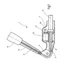
- the buckle device 1 comprises an elongate housing 11, the longitudinal direction of which is in the direction of travel, and a pyrotechnic tensioning unit 13, which is movable in the longitudinal direction and partially disposed within the housing 11 and otherwise projects forward.
- the buckle device 1 further comprises a mounted at the rear end of the housing 11 deflection 15, an obliquely upwardly and forwardly projecting from the deflection 15, designed as a helical spring spring 17 and arranged at the upper end of the spring 17 belt buckle 19 for receiving a belt tongue of the seat belt 5 on.
- the transmission means 21 thus acts between the tensioning unit 13 and the buckle 19 in the longitudinal direction of the transmission means 21 is movably and transversely flexible to the housing 11 is mounted.
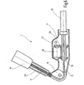
- a motor 25 is mounted, which is connected by means of a spur gear 27 in gear connection with a spindle nut 29.
- the spindle nut 29 is turned on a non-rotating, hollow spindle 31, which forms a rear part of the tensioning unit 13 and through which the transmission means 21 is guided to the rear.
- the rotatably mounted in the housing 11, the spindle nut 29 forms a support for the tensioning unit 13. In the starting position, the rear end of the spindle 31 is at least approximately within the spindle nut 29th
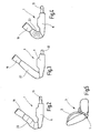
- the buckle device 1 performs in the event of a crash the known belt tensioner function, i. the tensioning unit 13 ignites, and a part thereof - supported on the part connected to the spindle 31 - moves forward, wherein it pulls down the belt buckle 19 against the force of the spring 17 via the transmission means 21.
- This crash position is shown in FIG. 4.
- the seat belt 5 latched to the buckle 19 is tightened, i. Any existing slack is eliminated so that the occupant makes the least possible way forward.
- the buckle device 1 also has a comfort function due to a positional change of the tensioner unit 13. If an occupant takes seat on the vehicle seat 3, as indicated by seat occupancy detection sensors, the motor 25 is driven to push the spindle 31 rearwardly via the spindle nut 29 , The entrained tensioning unit 13 also moves the transmission means 21 to the rear, so that the spring 17 can use the released path, the belt buckle 19 continue to extend, as shown in Fig. 3. The buckle 19 is thereby more easily accessible to the occupant. Once the seat belt 5 is fully applied, the motor 25 moves the spindle 31 forward, ie retracts the buckle 19 again until the optimum belt shape is reached and the belt slack is eliminated.
- the buckle 19 is also brought into the comfort position by the motor 25 after the crash, if still possible, to improve the accessibility to salvage the occupant.
Landscapes
- Engineering & Computer Science (AREA)
- Mechanical Engineering (AREA)
- Automotive Seat Belt Assembly (AREA)
Description
Die Erfindung betrifft eine Gurtschlossvorrichtung für einen Fahrzeugsitz mit den Merkmalen des Oberbegriffs des Anspruches 1.The invention relates to a buckle device for a vehicle seat with the features of the preamble of
Eine aus der
Der Erfindung liegt die Aufgabe zu Grunde, eine Gurtschlossvorrichtung der eingangs genannten Art zu verbessern. Diese Aufgabe wird erfindungsgemäß durch eine Gurtschlossvorrichtung mit den Merkmalen des Anspruches 1 gelöst. Vorteilhafte Ausgestaltungen sind Gegenstand der Unteransprüche.The invention is based on the object to improve a buckle device of the type mentioned. This object is achieved by a buckle device with the features of
Dadurch, dass die Position der Straffereinheit relativ zur Abstützung in Längsrichtung des Transmissionsmittels mittels eines Motors veränderlich ist, kann zusätzlich zu der Gurtstrafferfunktion noch eine gegenüber der Ausgangsposition des Gurtschlosses weiter ausgefahrene Komfortposition bereitgestellt werden, in welcher das Gurtschloss leichter zugänglich ist. Nach dem Anschnallen des Insassens wird dann das Gurtschloss wieder in die Ausgangsposition zurückgefahren. Der Antrieb erfolgt mittels des Motors, um einerseits eine bestimmte Bewegung zu definieren und andererseits den Komfort zu erhöhen. Durch die Positionsänderung der Straffereinheit wird das Gurtschloss mittels des Transmissionsmittels bewegt, d.h. Gurtschloss, Transmissionsmittel, Straffereinheit und Abstützung liegen bezüglich des beim Straffen und beim Beanspruchen des Gurtes auftretenden Kraftflusses in Reihe, d.h. für die zwei Möglichkeiten des Straffens des Gurtes (Crash, Komfort) ist eine serielle Lösung verwirklicht. In der Regel ist das Transmissionsmittel zugfest, druckfest und flexibel, wobei eine Feder oder ein anderer Kraftspeicher das Gurtschloss aufgerichtet halten kann.Characterized in that the position of the tensioning unit is variable relative to the support in the longitudinal direction of the transmission means by means of a motor, in addition to the belt tensioner function still opposite the initial position of the buckle extended extended comfort position can be provided, in which the buckle is easily accessible. After buckling the occupant then the buckle is moved back to the starting position. The drive is made by means of the motor, on the one hand to define a certain movement and on the other hand to increase comfort. By changing the position of the tensioner unit, the buckle is moved by means of the transmission means, ie buckle, transmission means, tensioning unit and support are in relation to the force flow occurring during tightening and straining the belt in series, ie for the two ways of tightening the belt (Crash, comfort) is a serial solution realized. In general, the transmission medium is tensile strength, pressure resistant and flexible, with a spring or other power storage can hold the buckle erect.
Als Schutz vor Verschmutzungen und Beschädigungen ist die Abstützung der Straffereinheit vorzugsweise in einem strukturfesten Gehäuse gelagert, welches vorzugsweise noch den Motor aufnimmt und an dem das Gurtschloss abgestützt ist, beispielsweise über eine Umlenkung und die besagte Feder. Die strukturfeste Anbringung des Gehäuses kann beispielsweise am Sitzrahmen, an der Oberschiene, an der Unterschiene oder an der Fahrzeugstruktur erfolgen.As a protection against dirt and damage, the support of the tensioning unit is preferably mounted in a structurally stable housing, which preferably still receives the motor and on which the buckle is supported, for example via a deflection and the said spring. The structure-fixed attachment of the housing can be done for example on the seat frame, on the upper rail, on the lower rail or on the vehicle structure.
In einer bevorzugten Ausführungsform ist die Abstützung als eine im Gehäuse drehbar gelagerte, durch den Motor angetriebene Spindelmutter ausgebildet, in welche eine Spindel eingedreht ist, wodurch die Motordrehung in eine Verschiebung der Straffereinheit umsetzbar ist bei gleichzeitiger Untersetzung. Die Spindel kann ein Bestandteil der Straffereinheit, d.h. des Straffergehäuses, sein oder optional gesondert ausgebildet und an dem Straffergehäuses anliegen oder angebracht sein. Um Bauraum zu sparen, ist das Transmissionsmittel vorzugsweise durch die dann hohl ausgebildete Spindel geführt.In a preferred embodiment, the support is designed as a rotatably mounted in the housing, driven by the motor spindle nut, in which a spindle is screwed, whereby the motor rotation can be converted into a displacement of the tightening unit with simultaneous reduction. The spindle may be a part of the tensioner unit, i. the Straffergehäuses, his or optionally separately formed and applied to the Straffergehäuses or be appropriate. To save space, the transmission means is preferably guided by the then hollow spindle.
Die Erfindung ist für alle Fahrzeugsitze mit Gurtstraffer anwendbar. Je nach Steuerung und vorhandenen Sensoren können verschiedene Situationen, wie beispielsweise Einsitzen, Öffnen der Türe, Abschalten des Motors oder ein erfolgter Crash, dazu führen, dass die Komfortposition eingenommen wird.The invention is applicable to all vehicle seats with belt tensioners. Depending on the controller and existing sensors, various situations, such as seating, opening the door, turning off the engine, or a crash may cause the comfort position to be taken.
Im folgenden ist die Erfindung anhand eines in der Zeichnung dargestellten Ausführungsbeispiels näher erläutert. Es zeigen
- Fig. 1
- einen Schnitt durch das Ausführungsbeispiel in der Komfortposition,
- Fig. 2
- eine Seitenansicht des Ausführungsbeispiels in der Ausgangsposition,
- Fig. 3
- eine Seitenansicht des Ausführungsbeispiels in der Komfortposition,
- Fig. 4
- eine Seitenansicht des Ausführungsbeispiels in der Crashposition,
- Fig. 5
- eine schematische Seitenansicht eines Fahrzeugsitzes, und
- Fig. 6
- einen Schnitt durch das Ausführungsbeispiel in der Ausgangsposition.
- Fig. 1
- a section through the embodiment in the comfort position,
- Fig. 2
- a side view of the embodiment in the starting position,
- Fig. 3
- a side view of the embodiment in the comfort position,
- Fig. 4
- a side view of the embodiment in the crash position,
- Fig. 5
- a schematic side view of a vehicle seat, and
- Fig. 6
- a section through the embodiment in the starting position.
Eine Gurtschloßvorrichtung 1 für einen Fahrzeugsitz 3 eines Kraftfahrzeuges ist tunnelseitig am Fahrzeugsitz 3 strukturfest angebracht und dient der lösbaren Befestigung eines Sicherheitsgurtes 5 des Fahrzeugsitzes 3. Die Anordnung des Fahrzeugsitzes 3 innerhalb des Kraftfahrzeuges und dessen gewöhnliche Fahrtrichtung definieren die nachfolgend verwendeten Richtungsangaben. Die Gurtschloßvorrichtung 1 weist ein längliches Gehäuse 11, dessen Längsrichtung in Fahrtrichtung liegt, und eine pyrotechnische Straffereinheit 13 auf, die in Längsrichtung beweglich ist und teilweise innerhalb des Gehäuses 11 angeordnet und ansonsten nach vorne übersteht. Die Gurtschloßvorrichtung 1 weist ferner eine am hinteren Ende des Gehäuses 11 angebrachte Umlenkung 15, eine von der Umlenkung 15 schräg nach oben und vorne abstehende, als Schraubenfeder ausgebildete Feder 17 und ein am oberen Ende der Feder 17 angeordnetes Gurtschloß 19 zur Aufnahme einer Gurtzunge des Sicherheitsgurtes 5 auf.A
Ein zugfestes, druckfestes und flexibles Transmissionsmittel 21, vorliegend ein Stahlseil, ist von der Straffereinheit 13 nach hinten über die Umlenkung 15 schräg nach oben und durch die Feder 17 hindurch zum Gurtschloß 19 geführt und an diesem befestigt. Das Transmissionsmittel 21 wirkt somit zwischen der Straffereinheit 13 und dem Gurtschloß 19, das in Längsrichtung des Transmissionsmittels 21 beweglich und quer dazu flexibel am Gehäuse 11 angebracht ist. Ein zwischen dem Gurtschloß 19 und der Umlenkung 15 angebrachter Balg 23, welcher um die Feder 17 herum angeordnet ist, schützt vor Schmutz und anderen Einwirkungen von außen. Im Gehäuse 11 ist ein Motor 25 gelagert, welcher mittels einer Stirnradstufe 27 in Getriebeverbindung mit einer Spindelmutter 29 steht. Die Spindelmutter 29 ist auf eine nichtdrehende, hohle Spindel 31 aufgedreht, welche einen hinteren Bestandteil der Straffereinheit 13 bildet und durch welche das Transmissionsmittel 21 nach hinten geführt ist. Die drehbar im Gehäuse 11 gelagerte Spindelmutter 29 bildet eine Abstützung für die Straffereinheit 13. In der Ausgangsposition befindet sich das hintere Ende der Spindel 31 wenigstens näherungsweise innerhalb der Spindelmutter 29.A tensile, pressure-resistant and flexible transmission means 21, in this case a steel cable, is guided by the
Die Gurtschloßvorrichtung 1 führt im Crashfall die bekannte Gurtstrafferfunktion aus, d.h. die Straffereinheit 13 zündet, und ein Teil desselben fährt - abgestützt an dem mit der Spindel 31 verbundenen Teil - nach vorne, wobei er über das Transmissionsmittel 21 das Gurtschloß 19 entgegen der Kraft der Feder 17 nach unten zieht. Diese Crashposition ist in Fig. 4 dargestellt. Der am Gurtschloß 19 eingeklinkte Sicherheitsgurt 5 wird gestrafft, d.h. eine eventuell vorhandene Gurtlose wird beseitigt, damit der Insasse einen möglichst geringen Weg nach vorne macht.The
Die Gurtschloßvorrichtung 1 hat auch eine Komfortfunktion aufgrund einer Positionsveränderung der Straffereinheit 13. Nimmt ein Insasse auf dem Fahrzeugsitz 3 Platz, was durch Sitzbelegungs-Erkennungssensoren gemeldet wird, wird der Motor 25 angesteuert, so daß er über die Spindelmutter 29 die Spindel 31 nach hinten schiebt. Die mitgeführte Straffereinheit 13 bewegt das Transmissionsmittel 21 ebenfalls nach hinten, so daß die Feder 17 den freigegebenen Weg nutzen kann, das Gurtschloß 19 weiter auszufahren, wie in Fig. 3 dargestellt. Das Gurtschloß 19 wird dadurch für den Insassen leichter erreichbar. Sobald der Sicherheitsgurt 5 vollständig angelegt ist, bewegt der Motor 25 die Spindel 31 nach vorne, d.h. zieht das Gurtschloß 19 wieder ein, bis der optimale Gurtverlauf erreicht und die Gurtlose beseitigt ist.The
In einer "postsafe"-fähigen Abwandlung wird nach dem Crash, soweit noch möglich, das Gurtschloß 19 durch den Motor 25 ebenfalls in die Komfortposition gebracht, um die Zugänglichkeit zur Bergung des Insassens zu verbessern.In a "postsafe" capable modification, the
- 11
- Gurtschloßvorrichtungbelt locking
- 33
- Fahrzeugsitzvehicle seat
- 55
- Sicherheitsgurtsafety belt
- 1111
- Gehäusecasing
- 1313
- Straffereinheittightening unit
- 1515
- Umlenkungredirection
- 1717
- Federfeather
- 1919
- Gurtschloßbuckle
- 2121
- Transmissionsmitteltransmission means
- 2323
- Balgbellows
- 2525
- Motorengine
- 2727
- Stirnradstufespur gear
- 2929
- Spindelmutter, AbstützungSpindle nut, support
- 3131
- Spindelspindle
Claims (8)
- Belt locking device for a vehicle seat, in particular for a motor vehicle seat, having a movably mounted belt lock (19) for a safety belt (5), a tightening unit (13), which is supported on a support (29) fixedly mounted in the structure, and a transmission means (21) acting between the tightening unit (13) and the belt lock (19), wherein, in the event of a crash, the tightening unit (13) pulls the belt lock (19) from an initial position into a crash position by means of the transmission means (21), wherein the position of the tightening unit (13) relative to the support (29) is alterable in the longitudinal direction of the transmission means (21), and a position change of the tightening unit (13) moves the belt lock (19) by means of the transmission means (21), characterised in that, for a comfort function, the position of the tightening unit (13) is alterable by a motor (25), wherein the belt lock (19) extends further after a passenger has sat down on the vehicle seat (3), and after the safety belt (5) has been put on completely the motor (25) retracts the belt lock (19) again.
- Belt locking device according to Claim 1, characterised in that the transmission means (21) is tension-stable and/or pressure-resistant and/or flexible.
- Belt locking device according to Claim 1 or 2, characterised in that the support (29) is mounted in a structure-fixed housing (11).
- Belt locking device according to Claim 3, characterised in that the motor (25) is arranged in the housing (11).
- Belt locking device according to Claim 3 or 4, characterised in that the support is a spindle nut (29), which is rotatably mounted in the housing (11) and is driven by the motor (25), and into which a spindle (31) is screwed.
- Belt locking device according to Claim 5, characterised in that the spindle (31) bears against the tightening unit (13), is mounted thereon and/or is a component part of the same.
- Belt locking device according to any one of Claims 1 to 6, characterised in that the belt lock (19), the transmission means (21), the tightening unit (13) and the support (29) are in series in respect of the force flow occurring during tightening and when the belt (5) is under load.
- Vehicle seat, in particular a motor vehicle seat, having a belt locking device (1) according to any one of Claims 1 to 7.
Applications Claiming Priority (2)
| Application Number | Priority Date | Filing Date | Title |
|---|---|---|---|
| DE10325473A DE10325473A1 (en) | 2003-06-05 | 2003-06-05 | Belt buckle device for a vehicle seat |
| PCT/EP2004/005632 WO2004108487A1 (en) | 2003-06-05 | 2004-05-26 | Belt buckling device for a vehicle seat |
Publications (2)
| Publication Number | Publication Date |
|---|---|
| EP1628859A1 EP1628859A1 (en) | 2006-03-01 |
| EP1628859B1 true EP1628859B1 (en) | 2007-06-27 |
Family
ID=33494847
Family Applications (1)
| Application Number | Title | Priority Date | Filing Date |
|---|---|---|---|
| EP04734819A Expired - Fee Related EP1628859B1 (en) | 2003-06-05 | 2004-05-26 | Belt buckling device for a vehicle seat |
Country Status (5)
| Country | Link |
|---|---|
| US (1) | US7178835B2 (en) |
| EP (1) | EP1628859B1 (en) |
| JP (1) | JP2006526536A (en) |
| DE (2) | DE10325473A1 (en) |
| WO (1) | WO2004108487A1 (en) |
Families Citing this family (24)
| Publication number | Priority date | Publication date | Assignee | Title |
|---|---|---|---|---|
| US20040232670A1 (en) * | 2002-03-12 | 2004-11-25 | Trw Vehicle Safety Systems Inc. | Apparatus for measuring tension in seat belt webbing |
| US20070235999A1 (en) * | 2006-04-06 | 2007-10-11 | Morra Mark A | Vehicle seat belt apparatus |
| DE102006032492A1 (en) * | 2006-07-13 | 2008-01-17 | Siemens Ag | Safety belt tightening unit for use in belt system of motor vehicle, has belt lock movably supported in tightening direction, and drive unit for tightening belt strap standing in effective connection with belt lock for moving buckle |
| FR2920121B1 (en) * | 2007-08-21 | 2009-11-06 | Renault Sas | MOTOR VEHICLE SAFETY SEAT BELT ARRANGEMENT |
| GB0724215D0 (en) | 2007-12-12 | 2008-01-23 | Norgren Ltd C A | Seat belt device |
| FR2953178B1 (en) * | 2009-11-27 | 2011-12-09 | Peugeot Citroen Automobiles Sa | SAFETY BELT DEVICE WITH VERTICAL ASSISTANCE SYSTEM OF THE ATTACHMENT LOOP |
| JP5523856B2 (en) * | 2010-01-29 | 2014-06-18 | 株式会社東海理化電機製作所 | Seat belt device |
| DE102011011777A1 (en) * | 2011-03-01 | 2012-09-06 | Trw Automotive Gmbh | Reversible buckle retractor for occupant restraint system of vehicle i.e. car, has seat harness release connected with end of driver, and pressure spring arranged between seat harness release and stop element |
| DE102011103820B4 (en) * | 2011-06-01 | 2020-10-22 | Autoliv Development Ab | Rope guide for a rope of a belt buckle |
| DE102011114497B4 (en) * | 2011-09-29 | 2013-08-29 | Autoliv Development Ab | Belt buckle for a seat belt device of a motor vehicle |
| CN203078469U (en) * | 2012-01-20 | 2013-07-24 | 德昌电机(深圳)有限公司 | Safety belt tongue plate actuator |
| CN103213558A (en) | 2012-01-20 | 2013-07-24 | 德昌电机(深圳)有限公司 | Safety belt buckle assembly |
| DE102012016211B4 (en) * | 2012-08-16 | 2023-06-15 | Zf Automotive Germany Gmbh | Seat belt buckle presenter |
| DE102013001030A1 (en) * | 2013-01-23 | 2014-07-24 | Daimler Ag | Seat belt buckle for a safety belt of a vehicle |
| JP6096537B2 (en) * | 2013-03-07 | 2017-03-15 | 株式会社東海理化電機製作所 | Mobile device |
| KR101739843B1 (en) * | 2014-01-22 | 2017-05-25 | 아우토리브 디벨롭먼트 아베 | Buckle presenter |
| JP5986152B2 (en) * | 2014-07-30 | 2016-09-06 | トヨタ自動車株式会社 | Lift-up buckle device |
| KR101674497B1 (en) | 2014-10-10 | 2016-11-10 | 아우토리브 디벨롭먼트 아베 | Buckle transmission apparatus |
| KR101674500B1 (en) | 2014-10-10 | 2016-11-10 | 아우토리브 디벨롭먼트 아베 | Mounting apparatua for buckle transmission apparatus |
| DE102014015340B4 (en) * | 2014-10-17 | 2019-07-18 | Trw Automotive Gmbh | Gurtschlossbringer |
| DE102015217151B4 (en) * | 2015-09-08 | 2022-08-18 | Autoliv Development Ab | Belt buckle for a safety belt device in a motor vehicle |
| JP6113874B1 (en) * | 2016-02-10 | 2017-04-12 | 株式会社東海理化電機製作所 | Buckle device |
| JP2018034550A (en) * | 2016-08-29 | 2018-03-08 | 株式会社東海理化電機製作所 | Buckle device |
| WO2018125680A1 (en) | 2016-12-30 | 2018-07-05 | Key Safety Systems, Inc. | Restraining system for a seat belt buckle |
Family Cites Families (29)
| Publication number | Priority date | Publication date | Assignee | Title |
|---|---|---|---|---|
| FR2268993B1 (en) * | 1974-04-23 | 1976-12-17 | Poudres & Explosifs Ste Nale | |
| DE3044834C2 (en) * | 1980-11-28 | 1982-10-07 | Hans-Hellmut Ing.(grad.) 2061 Sülfeld Ernst | Attachment for the buckle of a seat belt |
| DE3734152C2 (en) * | 1987-10-09 | 1998-04-09 | Gen Engineering Bv | Belt tightening of a lap belt end point via a pulling rope |
| DE3822253A1 (en) * | 1988-07-01 | 1990-01-04 | Bayerische Motoren Werke Ag | Tensioning device for safety belts in motor vehicles |
| GB2227642B (en) * | 1988-11-14 | 1993-01-06 | Autoliv Dev | Improvements in/relating to a seat belt pre-tensioner arrangement |
| EP0452521B1 (en) * | 1990-04-17 | 1994-08-10 | Trw Repa Gmbh | Triggering mechanism for tensioning devices in vehicles |
| JPH05254394A (en) * | 1992-03-11 | 1993-10-05 | Nissan Motor Co Ltd | Seat belt retractor |
| US5332261A (en) * | 1993-02-08 | 1994-07-26 | General Motors Corporation | Buckle positioning apparatus for improving occupant access in a motor vehicle |
| DE4332206C2 (en) * | 1993-09-22 | 1997-08-14 | Hs Tech & Design | Drive device |
| US5364129A (en) * | 1993-10-26 | 1994-11-15 | General Safety Corporation | Vehicle safety belt tensioning mechanism |
| US5607185A (en) * | 1993-11-26 | 1997-03-04 | Nippondenso Co., Ltd. | Belt tightener for seat belt |
| WO1996004154A1 (en) * | 1994-08-04 | 1996-02-15 | Alliedsignal Inc. | Method and apparatus for reducing occupant injury in frontal collisions |
| JP3464545B2 (en) * | 1994-11-08 | 2003-11-10 | 株式会社東海理化電機製作所 | Preloader device |
| US5564748A (en) * | 1995-09-27 | 1996-10-15 | Ford Motor Company | Seat belt buckle pretensioner with patterned frangible end cap |
| DE29608213U1 (en) * | 1996-05-06 | 1996-09-05 | Trw Repa Gmbh | Belt tensioners for a seat belt |
| US5887897A (en) * | 1997-02-06 | 1999-03-30 | Breed Automoive Technology, Inc. | Apparatus for pretensioning a vehicular seat belt |
| US5871236A (en) * | 1997-05-13 | 1999-02-16 | Trw Vehicle Safety Systems Inc. | Apparatus for pretensioning seat belt webbing |
| US6076856A (en) * | 1999-01-12 | 2000-06-20 | General Motors Corporation | Belt tension and energy absorbing apparatus |
| DE19941435C2 (en) * | 1999-08-30 | 2001-08-09 | Autoliv Dev | Multi-stage seat belt tensioner |
| DE19961799B4 (en) * | 1999-12-21 | 2004-03-25 | Breed Automotive Technology, Inc., Lakeland | Passive safety system of a motor vehicle |
| WO2001079042A2 (en) * | 2000-04-17 | 2001-10-25 | Joalto Design, Inc. | A seat belt buckle receptacle presenter assembly |
| WO2002009984A1 (en) * | 2000-08-01 | 2002-02-07 | Takata Seat Belts, Inc. | Method of and an apparatus for presenting a seat belt buckle |
| US6485058B1 (en) * | 2000-08-04 | 2002-11-26 | Breed Automotive Technology, Inc. | Seat belt buckle and tongue presenter system |
| US6550867B2 (en) * | 2001-05-10 | 2003-04-22 | Delphi Technologies, Inc. | Seat restraint buckle presenter assembly |
| JP4448626B2 (en) * | 2001-07-18 | 2010-04-14 | 本田技研工業株式会社 | Crew protection device |
| DE20208808U1 (en) * | 2002-06-06 | 2002-10-17 | Trw Repa Gmbh | Seat belt tensioning device |
| DE20209965U1 (en) * | 2002-06-27 | 2002-10-31 | Trw Repa Gmbh | buckle tensioner |
| US6869104B2 (en) * | 2003-02-06 | 2005-03-22 | Daimlerchrysler Corporation | Motorized adjustment of seat belt anchor position |
| US6969088B2 (en) * | 2003-04-29 | 2005-11-29 | General Motors Corporation | Seat belt buckle presenter and method of use therefor |
-
2003
- 2003-06-05 DE DE10325473A patent/DE10325473A1/en not_active Ceased
-
2004
- 2004-05-26 DE DE502004004193T patent/DE502004004193D1/en not_active Expired - Fee Related
- 2004-05-26 JP JP2006508203A patent/JP2006526536A/en not_active Withdrawn
- 2004-05-26 EP EP04734819A patent/EP1628859B1/en not_active Expired - Fee Related
- 2004-05-26 WO PCT/EP2004/005632 patent/WO2004108487A1/en active IP Right Grant
-
2005
- 2005-11-22 US US11/284,857 patent/US7178835B2/en not_active Expired - Fee Related
Non-Patent Citations (1)
| Title |
|---|
| None * |
Also Published As
| Publication number | Publication date |
|---|---|
| DE10325473A1 (en) | 2005-01-05 |
| DE502004004193D1 (en) | 2007-08-09 |
| EP1628859A1 (en) | 2006-03-01 |
| US20060076767A1 (en) | 2006-04-13 |
| WO2004108487A1 (en) | 2004-12-16 |
| US7178835B2 (en) | 2007-02-20 |
| JP2006526536A (en) | 2006-11-24 |
Similar Documents
| Publication | Publication Date | Title |
|---|---|---|
| EP1628859B1 (en) | Belt buckling device for a vehicle seat | |
| EP0439565B1 (en) | Safety device for motor vehicle passengers | |
| EP3268260B1 (en) | Steering column for a motor vehicle | |
| DE4436810C2 (en) | Belt retractor for a seat belt of a motor vehicle | |
| EP1029746A2 (en) | Roll-over protection for motor vehicles | |
| EP0189410A1 (en) | Safety device for vehicle. | |
| WO2006010484A1 (en) | Seat belt extender that extends toward the vehicle occupant | |
| DE19519297A1 (en) | Side airbag for vehicle | |
| DE102010052909B4 (en) | Locking device for adjustable motor vehicle steering column | |
| DE102018218293A1 (en) | Belt retractor | |
| EP1072485A2 (en) | Seat belt system | |
| EP1452409B1 (en) | Seatbelt pretensioner with a height-adjustable belt guide | |
| EP1955908B1 (en) | Rollover protection system for motor vehicles with a sensor-controlled, actively positioned rollover body | |
| DE102007033154B4 (en) | Safety belt system for a motor vehicle | |
| WO2001085495A2 (en) | Safety belt winder with a reversible belt tensioner | |
| DE102019206439B4 (en) | Belt retractor | |
| DE10039802B4 (en) | Safety device for the occupants of a vehicle, in particular of a motor vehicle | |
| EP1632408A2 (en) | Safety belt connection device | |
| WO2022049013A1 (en) | Belt retractor | |
| DE102007004977A1 (en) | Vehicle safety belt system has belt lock attached to tensioning system comprising spring attached at its free end to cog belt, manual lever on seat back carrying toothed sector cooperates with cog belt to tension seat belt | |
| WO2004089686A1 (en) | Height-adjustable motor vehicle seat | |
| WO2024023007A1 (en) | Belt retractor for a seatbelt device of a motor vehicle | |
| DE102017130638A1 (en) | Rollover protection system for vehicle front windscreen frame | |
| EP0757947A1 (en) | Pyrotechnic pretensioner | |
| DE102004003204A1 (en) | Motor vehicle e.g. cabrio, seat, has shaft coupled with belt locked device, which blocks rotational movement of shaft from defined speed, and driving device rotationally driving shaft against pulling direction of pulling unit |
Legal Events
| Date | Code | Title | Description |
|---|---|---|---|
| PUAI | Public reference made under article 153(3) epc to a published international application that has entered the european phase |
Free format text: ORIGINAL CODE: 0009012 |
|
| 17P | Request for examination filed |
Effective date: 20050205 |
|
| AK | Designated contracting states |
Kind code of ref document: A1 Designated state(s): DE FR GB IT |
|
| DAX | Request for extension of the european patent (deleted) | ||
| RBV | Designated contracting states (corrected) |
Designated state(s): DE FR GB IT |
|
| GRAP | Despatch of communication of intention to grant a patent |
Free format text: ORIGINAL CODE: EPIDOSNIGR1 |
|
| GRAS | Grant fee paid |
Free format text: ORIGINAL CODE: EPIDOSNIGR3 |
|
| GRAA | (expected) grant |
Free format text: ORIGINAL CODE: 0009210 |
|
| AK | Designated contracting states |
Kind code of ref document: B1 Designated state(s): DE FR GB IT |
|
| REG | Reference to a national code |
Ref country code: GB Ref legal event code: FG4D Free format text: NOT ENGLISH |
|
| REF | Corresponds to: |
Ref document number: 502004004193 Country of ref document: DE Date of ref document: 20070809 Kind code of ref document: P |
|
| GBT | Gb: translation of ep patent filed (gb section 77(6)(a)/1977) |
Effective date: 20070925 |
|
| ET | Fr: translation filed | ||
| PLBE | No opposition filed within time limit |
Free format text: ORIGINAL CODE: 0009261 |
|
| STAA | Information on the status of an ep patent application or granted ep patent |
Free format text: STATUS: NO OPPOSITION FILED WITHIN TIME LIMIT |
|
| 26N | No opposition filed |
Effective date: 20080328 |
|
| PGFP | Annual fee paid to national office [announced via postgrant information from national office to epo] |
Ref country code: DE Payment date: 20080530 Year of fee payment: 5 |
|
| PGFP | Annual fee paid to national office [announced via postgrant information from national office to epo] |
Ref country code: IT Payment date: 20080527 Year of fee payment: 5 |
|
| PGFP | Annual fee paid to national office [announced via postgrant information from national office to epo] |
Ref country code: GB Payment date: 20080407 Year of fee payment: 5 |
|
| GBPC | Gb: european patent ceased through non-payment of renewal fee |
Effective date: 20090526 |
|
| REG | Reference to a national code |
Ref country code: FR Ref legal event code: ST Effective date: 20100129 |
|
| PG25 | Lapsed in a contracting state [announced via postgrant information from national office to epo] |
Ref country code: FR Free format text: LAPSE BECAUSE OF NON-PAYMENT OF DUE FEES Effective date: 20090602 |
|
| PGFP | Annual fee paid to national office [announced via postgrant information from national office to epo] |
Ref country code: FR Payment date: 20080424 Year of fee payment: 5 |
|
| PG25 | Lapsed in a contracting state [announced via postgrant information from national office to epo] |
Ref country code: GB Free format text: LAPSE BECAUSE OF NON-PAYMENT OF DUE FEES Effective date: 20090526 |
|
| PG25 | Lapsed in a contracting state [announced via postgrant information from national office to epo] |
Ref country code: DE Free format text: LAPSE BECAUSE OF NON-PAYMENT OF DUE FEES Effective date: 20091201 |
|
| PG25 | Lapsed in a contracting state [announced via postgrant information from national office to epo] |
Ref country code: IT Free format text: LAPSE BECAUSE OF NON-PAYMENT OF DUE FEES Effective date: 20090526 |