EP1625829A1 - Ultrasonogram generation method - Google Patents
Ultrasonogram generation method Download PDFInfo
- Publication number
- EP1625829A1 EP1625829A1 EP04733985A EP04733985A EP1625829A1 EP 1625829 A1 EP1625829 A1 EP 1625829A1 EP 04733985 A EP04733985 A EP 04733985A EP 04733985 A EP04733985 A EP 04733985A EP 1625829 A1 EP1625829 A1 EP 1625829A1
- Authority
- EP
- European Patent Office
- Prior art keywords
- ultrasonic
- body cavity
- dimensional
- reference position
- ultrasonic image
- Prior art date
- Legal status (The legal status is an assumption and is not a legal conclusion. Google has not performed a legal analysis and makes no representation as to the accuracy of the status listed.)
- Granted
Links
Images


Classifications
-
- A—HUMAN NECESSITIES
- A61—MEDICAL OR VETERINARY SCIENCE; HYGIENE
- A61B—DIAGNOSIS; SURGERY; IDENTIFICATION
- A61B8/00—Diagnosis using ultrasonic, sonic or infrasonic waves
- A61B8/13—Tomography
- A61B8/14—Echo-tomography
-
- A—HUMAN NECESSITIES
- A61—MEDICAL OR VETERINARY SCIENCE; HYGIENE
- A61B—DIAGNOSIS; SURGERY; IDENTIFICATION
- A61B8/00—Diagnosis using ultrasonic, sonic or infrasonic waves
- A61B8/12—Diagnosis using ultrasonic, sonic or infrasonic waves in body cavities or body tracts, e.g. by using catheters
-
- A—HUMAN NECESSITIES
- A61—MEDICAL OR VETERINARY SCIENCE; HYGIENE
- A61B—DIAGNOSIS; SURGERY; IDENTIFICATION
- A61B8/00—Diagnosis using ultrasonic, sonic or infrasonic waves
- A61B8/52—Devices using data or image processing specially adapted for diagnosis using ultrasonic, sonic or infrasonic waves
- A61B8/5269—Devices using data or image processing specially adapted for diagnosis using ultrasonic, sonic or infrasonic waves involving detection or reduction of artifacts
- A61B8/5276—Devices using data or image processing specially adapted for diagnosis using ultrasonic, sonic or infrasonic waves involving detection or reduction of artifacts due to motion
-
- G—PHYSICS
- G06—COMPUTING; CALCULATING OR COUNTING
- G06T—IMAGE DATA PROCESSING OR GENERATION, IN GENERAL
- G06T7/00—Image analysis
- G06T7/30—Determination of transform parameters for the alignment of images, i.e. image registration
- G06T7/33—Determination of transform parameters for the alignment of images, i.e. image registration using feature-based methods
-
- G—PHYSICS
- G06—COMPUTING; CALCULATING OR COUNTING
- G06T—IMAGE DATA PROCESSING OR GENERATION, IN GENERAL
- G06T7/00—Image analysis
- G06T7/60—Analysis of geometric attributes
- G06T7/66—Analysis of geometric attributes of image moments or centre of gravity
-
- G—PHYSICS
- G06—COMPUTING; CALCULATING OR COUNTING
- G06T—IMAGE DATA PROCESSING OR GENERATION, IN GENERAL
- G06T2207/00—Indexing scheme for image analysis or image enhancement
- G06T2207/10—Image acquisition modality
- G06T2207/10132—Ultrasound image
-
- G—PHYSICS
- G06—COMPUTING; CALCULATING OR COUNTING
- G06T—IMAGE DATA PROCESSING OR GENERATION, IN GENERAL
- G06T2207/00—Indexing scheme for image analysis or image enhancement
- G06T2207/30—Subject of image; Context of image processing
- G06T2207/30004—Biomedical image processing
- G06T2207/30028—Colon; Small intestine
-
- G—PHYSICS
- G06—COMPUTING; CALCULATING OR COUNTING
- G06T—IMAGE DATA PROCESSING OR GENERATION, IN GENERAL
- G06T2207/00—Indexing scheme for image analysis or image enhancement
- G06T2207/30—Subject of image; Context of image processing
- G06T2207/30004—Biomedical image processing
- G06T2207/30061—Lung
-
- G—PHYSICS
- G06—COMPUTING; CALCULATING OR COUNTING
- G06T—IMAGE DATA PROCESSING OR GENERATION, IN GENERAL
- G06T2207/00—Indexing scheme for image analysis or image enhancement
- G06T2207/30—Subject of image; Context of image processing
- G06T2207/30004—Biomedical image processing
- G06T2207/30101—Blood vessel; Artery; Vein; Vascular
Definitions
- An ultrasonic image generating method for generating an ultrasonic image based on ultrasonic echo data obtained by transmitting/receiving ultrasonic waves to/from an inspection object includes a reference position setting step for determining the reference position on each image with respect to a plurality of consecutive two-dimensional tomograms; a correction step for obtaining regular and consecutive two-dimensional tomograms by correcting irregularity of the reference position of each of the two-dimensional tomograms determined by the reference position setting step; and an ultrasonic image generating step for generating the ultrasonic images based on the regular and consecutive two-dimensional tomograms corrected by the correction step.
- the position detecting section 32 acquires position data on the distal end section 11a of the ultrasonic probe 2 in the body cavity, and outputs the acquired pieces of position data to the image processing section 33, one after another.
- the image processing section 33 extracts surface coordinates of each of the images, and determines surface extraction points (step S2).
- the image processing section 33 acquires consecutive radial images Gr corrected in correction steps (S4 to S7), and associates these consecutive radial images Gr with position data detected by the position detecting section 32 based on the above-described consecutive radial images Gr, whereby the image processing section 33 performs an ultrasonic image generating step (step S8) for generating an ultrasonic image (three-dimensional image) Gs.
- the image processing section 33 can generate an ultrasonic image (three-dimensional image) Gs with the body cavity surface 72 being smooth as shown in Fig. 11.
- step S5 In the ultrasonic image generating method and ultrasonic image generating program according to the first embodiment, the above-described smoothing processing in step S5 and expanding/contraction processing in step S7 have been described by assuming the Cartesian coordinate system.
- the ultrasonic probe 2B includes an elongated, flexible insertion section 11 that can be inserted into a body cavity; a drive section 12 to which the proximal end of the insertion section 11 is detachably connected.
- the insertion section 11 incorporates, in its distal end section 11a, an ultrasonic transducer 2a for transmitting/receiving ultrasonic waves to/form this distal end section 11a.
- the ultrasonic transducer 2a is attached to the distal end of a flexible shaft 21.
- its distal end section 11a is covered with an acoustic cap that transmits ultrasonic waves.
- the surroundings of the ultrasonic transducer 2a are filled with ultrasonic propagation media (not shown) that transmit (propagate) ultrasonic waves.
- a signal line (not shown) extends from the ultrasonic transducer 2a, and is connected to an ultrasonic observation section 31 in the apparatus main body 3B via the drive section 12.
- the image processing section 33B has a function as control means for moving a selected operation object relative to the movement of the mouse 34, based on the selection of the operation object in a screen operation by the mouse 34. Also connected to the image processing section 33B, is a large-capacity external storage device (not shown) for recording image data or the like through an interface (not shown).
- the smoothing (averaging) of the surface positions of the radial image Gr is performed by using surface extraction points of the n-th surface and the (n-1)th surface of the radial image Gr.
- the number of surfaces of the radial images Gr to be referred to for smoothing as many surfaces as exist within the range of 2 mm in the Z-axis direction, i.e., longitudinal direction (8 surfaces for 0. 25 mm pitch, and 4 surfaces for 0.5 mm pitch) are used to perform averaging, whereby the surface positions of the body cavity surface are smoothed.
Abstract
Description
- The present invention relates to an ultrasonic image generating method for generating an ultrasonic image based on ultrasonic echo data obtained by transmitting/receiving ultrasonic waves to/from an inspection object.
- In recent years, ultrasonic diagnostic apparatuses have come into wide use in medical and industrial fields. The ultrasonic diagnostic apparatuses are for noninvasively diagnosing the inside of an inspection object by transmitting/receiving ultrasonic waves to/from the inspection object.
- These conventional ultrasonic diagnostic apparatuses are provided with an ultrasonic image generating method for generating an three-dimensional ultrasonic (cubic) image constructed by two-dimensional tomograms, such as radial images (cross sections perpendicular to the scan axis of an ultrasonic transducer) and linear images (cross sections horizontal to the scan axis of the ultrasonic transducer), based on ultrasonic echo data obtained by transmitting/receiving ultrasonic waves to/from the inspection object.
- As such a conventional ultrasonic image generating method, for example, as shown in Japanese Unexamined Patent Application Publication No. 2000-254123, a method has been proposed by which a three-dimensional image extracted from a body cavity surface is generated in order to facilitate three-dimensionally recognizing an ultrasonic image.
- In general, one problem associated with a tomogram is the "pulsation" of a human body.
- Typically, the ultrasonic diagnostic apparatus performs a helical scan by causing the ultrasonic transducer to radially scan (i.e., scan perpendicularly to the scan axis of the ultrasonic transducer), and causing it to linearly scan (i.e., scan horizontally to the scan axis of the ultrasonic transducer), and thereby acquires two-dimensional tomograms such as the above-described radial image and linear image. Here, the helical scan requires a time of, e.g., about 2 to 4 sec.
- However, in the above-described conventional ultrasonic image generating method, the positions of a region of interest usually causes deviation between the scan starting time and scan finishing time due to the pulsation occurring for the time period of about 2 to 4 sec during which the above-described helical scan is performed. This "deviation" causes a problem chiefly in the above-described linear image. When the extent of the deviation is too large, even if the linear image is constructed, it may not bring about a clear image.
- Possible causes of the deviation in the linear image include elements shown in the following table 1 besides the pulsation.
[TABLE 1] Causes Features Pulsation About 70 times per min; periodic, small, and vigorous movement Peristalsis On the order of once every several seconds; periodic, large, and slow movement Fluctuation of Probe Irregular and slow movement Respiratory Movement Irregular and slow movement - The ultrasonic image generating method set forth in the above-described Japanese Unexamined Patent Application Publication No. 2000-254123 involves a problem in that, when the images of an organ with blood vessels running adjacently thereto are converted into a three-dimensional image, the organ shifts under the influence of the pulsation, thereby distorting the image.
- In contrast to this, among the conventional ultrasonic image generating methods, a method has been proposed that attempts to eliminate pulsation, for example, as set forth in Japanese Unexamined Patent Application Publication No. 2000-316864.
- However, the ultrasonic image generating method set forth in the above-described Japanese Unexamined Patent Application Publication No. 2000-316864 has attained an effect to a certain extent on the elimination of pulsation, but the elimination effect thereof is not yet sufficient. This being the situation, a more effective ultrasonic image generating method has been demanded.
- On the other hand, among the conventional ultrasonic image generating methods, a method has been proposed that attempts to stabilize ultrasonic images by determining the barycenter of a body cavity, as set forth in Japanese Patent No. 331626.
- However, the ultrasonic image generating method set forth in the above-described Japanese Patent No. 3316268 has only the effect of stabilizing two-dimensional tomograms on a monitor, and even if this method is as-is applied to an ultrasonic image with a three-dimensional spread (i.e., three-dimensional image) for eliminating the influence of pulsation, it would produce no effect.
- The present invention has been made in light of the above-described situations, and aims to provide an ultrasonic image generating method capable of eliminating the influence of pulsation and acquiring high-quality ultrasonic images.
- An ultrasonic image generating method for generating an ultrasonic image based on ultrasonic echo data obtained by transmitting/receiving ultrasonic waves to/from an inspection object, according to the present invention, includes a reference position setting step for determining the reference position on each image with respect to a plurality of consecutive two-dimensional tomograms; a correction step for obtaining regular and consecutive two-dimensional tomograms by correcting irregularity of the reference position of each of the two-dimensional tomograms determined by the reference position setting step; and an ultrasonic image generating step for generating the ultrasonic images based on the regular and consecutive two-dimensional tomograms corrected by the correction step.
-
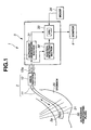
- Fig. 1 is a block diagram showing the overall configuration of an ultrasonic diagnostic system according to a first embodiment of the present invention.
- Fig. 2 is a representation of concrete examples of two-dimensional tomograms (radial images) Gr.
- Fig. 3 is a schematic view of an ultrasonic image (three-dimensional image) Gs.
- Fig. 4 is a flowchart showing an ultrasonic image generating method in the ultrasonic diagnostic system according to the first embodiment.
- Fig. 5 is a diagram showing images when determining surface extraction points by extracting surface coordinates.
- Fig. 6 is a diagram showing images when determining a barycenter by generating a polygon formed by connecting surface extraction points.
- Fig. 7 is a diagram showing two images when corresponding positions on the body cavity surface on the two radial images are mutually deviated between the two radial images even though these images depict the same body cavity.
- Fig. 8 is a diagram showing two images when barycenters of the two radial images are caused to coincide with each other by adjusting the positions of these images.
- Fig. 9 is a diagram showing an image when a body cavity surface has become smooth as a result of the smoothing.
- Fig. 10 is a diagram showing images when corresponding surface positions of the body cavity surfaces do not coincide between before and after the smoothing.
- Fig. 11 is a representation of a concrete example of an ultrasonic image (three-dimensional image) Gs.
- Fig. 12 is a diagram showing that radial images Gr are each formed of several hundred pieces of sound ray data.
- Fig. 13 is a block diagram showing the overall configuration of an ultrasonic diagnostic system according to a second embodiment of the present invention.
- Fig. 14 is a schematic view showing a sound ray when scanning a surface position of a body cavity surface.
- Fig. 15 is a histogram showing the frequency with respect to the luminance produced by sampling a predetermined number of sound rays with respect to all sound rays.
- Fig. 16. is a first schematic view when determining an object as a living body tissue with respect to a scan line by a sound ray.
- Fig. 17 is a second schematic view when determining an object as a living body tissue with respect to a scan line by a sound ray.
- Fig. 18 is a schematic view showing a correction processing for erroneous extraction.
- Fig. 19 is a first explanatory diagram showing a concrete example for determining the body cavity center (X, Y) as a reference position.
- Fig. 20 is a second explanatory diagram showing a concrete example for determining the body cavity center (X, Y) as a reference position.
- Fig. 21 is a schematic view showing processing for smoothing the positions on a body cavity surface using prior and subsequent images.
- Fig. 22 is a schematic view when distance correction processing is performed so that sound ray data is converted into radial images, and that the surface positions of the body cavity surface before smoothing (i.e., surface coordinates before smoothing) coincide with the surface positions of the smoothed body cavity (i.e., surface coordinates after the smoothing).
- Fig. 23 is a flowchart showing an ultrasonic image generating method in an ultrasonic diagnostic system according to a second embodiment.
- Fig. 24 is a flowchart showing a subroutine for determining the surface extraction points in Fig. 23.
- Fig. 25 is a first ultrasonic image example that has been conventionally obtained.
- Fig. 26 is the first ultrasonic image example subjected to processing based on the flowchart in Fig. 23.
- Fig. 27 is a second ultrasonic image example that has been conventionally obtained.
- Fig. 28 is the second ultrasonic image example subjected to processing based on the flowchart in Fig. 23.
- As shown in Fig. 1, an ultrasonic
diagnostic system 1 according to a first embodiment includes, in the main section thereof, anultrasonic probe 2 incorporating therein anultrasonic transducer 2a described later; the apparatus main body (ultrasonic image processing apparatus) 3 for generating an ultrasonic image by signal-processing ultrasonic echo signals received by theultrasonic probe 2; and amonitor 4 for displaying ultrasonic images in real time by inputting output image signals outputted from the apparatusmain body 3. - The
ultrasonic probe 2 includes an elongated,flexible insertion section 11 that can be inserted into a body cavity; adrive section 12 to which the proximal end of theinsertion section 11 is detachably connected. Theinsertion section 11 incorporates, in its distal end section 11a, anultrasonic transducer 2a for transmitting/receiving ultrasonic waves to/form this distal end section 11a. - The
ultrasonic transducer 2a is attached to the distal end of aflexible shaft 21. Here, in theultrasonic probe 2, its distal end section 11a is covered with an acoustic cap transmitting ultrasonic waves. The surroundings of theultrasonic transducer 2a are filled with ultrasonic propagation media (not shown) transmitting (propagating) ultrasonic waves. A signal line (not shown) extends from theultrasonic transducer 2a, and is connected to anultrasonic observation section 31 described later in the apparatusmain body 3 via thedrive section 12. - The
ultrasonic probe 2 is adapted to drive a first motor (not shown) incorporated in thedrive section 12 to rotationally drive theultrasonic transducer 2a, so that theultrasonic transducer 2a performs radial scans. Furthermore, theultrasonic probe 2 is adapted to drive a second motor (not shown) incorporated in thedrive section 12 to reciprocate theflexible shaft 21 in the axial direction (i.e., longitudinal direction; for example, referred to as a Z-axis direction) of theinsertion section 11, so that theultrasonic transducer 2a can reciprocate and perform a linear scan. - Specifically, the
ultrasonic probe 2 rotationally drives the first and second motors in thedrive section 12 simultaneously by synchronizing them, so that theultrasonic transducer 2a can transmit/receive ultrasonic waves in a spiral manner, and perform a helical scan a three-dimensional region in an inspection object. As a result, the apparatusmain body 3 can obtain a large number of two-dimensional tomograms varying in the coordinate position in the Z-axis direction from one position to another, little by little, and thereby an ultrasonic image (three-dimensional image) can be constructed from these two-dimensional tomograms. - In the
ultrasonic probe 2, itsdrive section 12 is connected to the apparatusmain body 3 by thecable 12a. - The apparatus
main body 3 comprises theultrasonic observation section 31 that transmits/receives ultrasonic signals to/from theultrasonic transducer 2a to obtain ultrasonic echo data in a three-dimensional region; aposition detecting section 32 for obtaining position data on the distal end section 11a of theultrasonic probe 2 in a body cavity (e.g., stomach 20); animage processing section 33 that is used for obtaining ultrasonic image data based on data by theposition detecting section 32 andultrasonic observation section 31, that specifies the position of a radial scan surface by associating position data from theposition detecting section 32 with two-dimensional tomograms, and that has a CPU generating an ultrasonic image (three-dimensional image) based on an ultrasonic image generating method and ultrasonic image generating program each described later. - Connected to the
image processing section 33 through an interface (not shown), is amouse 34 serving as screen operating means for allowing images as shown in Figs. 2 and 3 to be operated in an interactive manner. Themouse 34 has a function of performing a screen operation using a mouse cursor with respect to image information displayed on the display screen of themonitor 4. - The
image processing section 33 has a function as control means for moving a selected operation object relative to the movement of themouse 34, based on the selection of the operation object in a screen operation by themouse 34. Also connected to theimage processing section 33, is a large-capacity external storage device (not shown) for recording image data or the like via an interface (not shown). - The
image processing section 33 performs helical scans on thetransducer 2a in predetermined pitch units; coordinate-converts ultrasonic echo data obtained in theultrasonic observation section 31; and generates a plurality of two-dimensional tomograms (hereinafter referred to as radial images) Gr of cross sections substantially perpendicular to the axial direction (Z-axis direction) of theinsertion section 11, as shown in Fig. 2. These generated radial images Gr correspond to, for example, ultrasonic tomographic planes 20A in astomach 20 shown in Fig. 1. - Then, the
image processing section 33 generates a pseudo ultrasonic image (three-dimensional image) Gs as shown in Fig. 3 by associating a plurality of radial images Gr consecutively obtained in predetermined pitch units with position data on the distal end section 11a of theultrasonic probe 2, the position data having been detected in theposition detecting section 32. - Here, however, the organ moves under the influence of pulsation, resulting in a distorted ultrasonic image (three-dimensional image) Gs.
- With this being the situation, in this embodiment, the influence of pulsation is eliminated by the ultrasonic image generating method and ultrasonic image generating program described below.
- With reference to Figs. 5 to 11, these ultrasonic image generating method and ultrasonic image generating program will be explained based on a flowchart shown in Fig. 4.
- First, as described in Fig. 1, the
ultrasonic probe 2 rotationally drives the first and second motors in thedrive section 12 simultaneously by synchronizing them, so that theultrasonic transducer 2a performs helical scans in predetermined pitch units. - Thereupon, in the apparatus
main body 3, ultrasonic echo signals in a three-dimensional region received by theultrasonic transducer 2a are inputted into theultrasonic observation section 31. Theultrasonic observation section 31 receives the ultrasonic echo signals in the three-dimensional region, from theultrasonic transducer 2a, and coordinate-converts these ultrasonic echo signals to generate a plurality of consecutive radial images Gr. Then, theimage processing section 33 receives input of the pieces of image data on the radial images Gr from theultrasonic observation section 31 one after another, thereby acquiring the plurality of consecutive radial images Gr (step S1). - Simultaneously, the
position detecting section 32 acquires position data on the distal end section 11a of theultrasonic probe 2 in the body cavity, and outputs the acquired pieces of position data to theimage processing section 33, one after another. - Then, the
image processing section 33 specifies the position of a radial scan surface by associating each piece of position data from theposition detecting section 32 with a respective one of the plurality of consecutive radial images Gr. - Then, as reference position setting step for determining the reference position on each image with respect to the plurality of consecutive radial images Gr, the
image processing section 33 performs the following processes of steps S2 and S3. - First, with respect to the plurality of consecutive radial images Gr, the
image processing section 33 extracts surface coordinates of each of the images, and determines surface extraction points (step S2). - Here, for example, in an
image 40 shown in Fig. 5, theimage processing section 33 issues searchlines 40a from the image center, and extracts portions each exhibiting a large luminance change as surface coordinates, thereby determining the surface extraction points 41. - Next, the
image processing section 33 determines a barycenter as a reference position on each of the images with respect to a plurality of consecutive radial images Gr (step S3). - Here, for example, the
image processing section 33 generates apolygon 42 formed by connecting surface extraction points 41 as shown in Fig. 6, and determines abarycenter 43. - Generally, the barycenters of the
polygon 42 include a physical barycenter and geometric barycenter. - In this embodiment, the
barycenter 43 of the polygon is determined by a physical barycenter thereof. However, thebarycenter 43 may also be determined by a geometric barycenter. - Also, after having generated the
polygon 42, theimage processing section 33 may approximate thepolygon 42 by a circle (not shown) in which thepolygon 42 is substantially inscribed, and may determine the center point of this circle as a barycenter. - Next, as correction steps for acquiring consecutive radial images Gr by correcting irregularities of the
barycenters 43 with respect to the respective radial images Gr determined in the reference position setting steps (S2 and S3), theimage processing section 33 performs the following processes of steps S4 to S7. - Here, under the influence of pulsation and/or due to mechanical shakes of the probe itself, the plurality of consecutive radial images Gr deviates from each other, for example, as shown in Fig. 7.
- As shown in Fig. 7, even though a
radial image Gr 51 andradial image Gr 52 depict the same body cavity, the positions of body cavity surfaces 51B and 52B deviate from each other. - Hence, in this embodiment, the
image processing section 33 performs processing for shifting each of the plurality of radial images Gr to adjust the positions of these images, and thereby causing the barycenters on the images determined in S3 to coincide (align) with each other (step S4). - For example, as shown in Fig. 8, the
image processing section 33 adjusts the positions of theradial image Gr 51 andradial image Gr 52 by shifting their positions in up-and-down and left-and right directions, thereby causing thebarycenters - At this time, the
image processing section 33 may shift the image positions of theradial image Gr 52 in the up-and-down and left-and-right directions while fixing the image positions of theradial image Gr 51 specified by the user, and vice versa. Thereby, theimage processing section 33 can reduce big "fluctuations" due to mechanical factor. - However, the image shown in Fig. 8 still leaves
small fluctuations 54. - Hence, the apparatus
main body 3 uses prior and subsequent images to perform processing for smoothing the surface extraction points of a predetermined radial image Gr sandwiched by these images, and thereby smoothing the positions of a body cavity surface (step S5). - Here, the
image processing section 33 determines the number of pieces of data to be referred to, for smoothing, using the following expression (1):
- Here, the term "pitch" refers to the distance between two-dimensional tomograms (radial images Gr).
- For example, for 0.25 mm pitch, the count of pieces of reference data for smoothing is 16, and for 1 mm pitch, the above-described count is 4.
- Also, the image to be referred to is determined by the following expression (2):

- Here, n is a numeral value starting from 1 and ending at [(count of reference images) - 1].
- For example, let the total count of images be 10 (No. 0 to No. 9), and the pitch be 1 mm pitch (i.e., 4 images are referred to for smoothing). Here, when smoothing is applied to No. 5, the images to be referred to are Nos. 3, 4, 5, and 6.
- As described above, the
image processing section 33 uses prior and subsequent images to smooth the surface extraction points of a predetermined radial image Gr sandwiched by these images, and thereby smoothes the positions of the body cavity surfaces. - Then, as the result of the above-described smoothing by the
image processing section 33, for example, as shown in Fig. 9, theimage 55 constituted of theradial image Gr 51 andradial image Gr 52 becomes smoothed in thebody cavity surface 55B thereof. Here, thereference character 55A denotes the barycenter of theimage 55. - Here, regarding the radial image Gr, for example, as in the case of an
image 60 shown in Fig. 10, there is a case where the surface positions of thebody cavity surface 61 before smoothing (i.e., the positions of an extracted body cavity surface), and the surface positions of the smoothedbody cavity surface 62 do not coincide. Here, thereference character 63 denotes the difference between the surface position of thebody cavity surface 61 before smoothing (i.e., the position of the extracted body cavity surface) and the surface position of the smoothedbody cavity surface 62. - At this time, for example, in an ultrasonic image (three-dimensional image)
Gs 70 shown in Fig. 11, aside cross-section 71 thereof cannot be generated from radial images Gr in accordance with a smoothed body cavity surface. - It is therefore necessary to deform the
image 60 shown in Fig. 10 so that the surface positions of thebody cavity surface 61 before smoothing (i.e., the position of the extracted body cavity surface) and the surface positions of the smoothedbody cavity surface 62 mutually coincide. - Accordingly, the
image processing section 33 now performs processing for calculating the differences between the surface positions of the body cavity surface before smoothing (i.e., the positions of the extracted body cavity surface) and the surface positions of the smoothed body cavity surface, and then performs processing for expanding/contracting a predetermined radial image Gr based on the above-described calculated differences (steps S6 and S7). - Here, in the radial image Gr shown in Fig. 10, the
image processing section 33 calculates thedifferences 63 between the positions of thebody cavity surface 61 before smoothing (i.e., the positions of the extracted body cavity surface) and the positions of the smoothedbody cavity surface 62, and expands/contracts the image, based on the above-describedcalculated differences 63. - This allows the
image processing section 33 to generate a radial image Gr capable of being conformed to the body cavity surface after the smoothing. - Then, the
image processing section 33 acquires consecutive radial images Gr corrected in correction steps (S4 to S7), and associates these consecutive radial images Gr with position data detected by theposition detecting section 32 based on the above-described consecutive radial images Gr, whereby theimage processing section 33 performs an ultrasonic image generating step (step S8) for generating an ultrasonic image (three-dimensional image) Gs. - Thus, the
image processing section 33 can generate an ultrasonic image (three-dimensional image) Gs with thebody cavity surface 72 being smooth as shown in Fig. 11. - In the ultrasonic image generating method and ultrasonic image generating program according to the first embodiment, the above-described smoothing processing in step S5 and expanding/contraction processing in step S7 have been described by assuming the Cartesian coordinate system.
- However, intrinsically, the radial image Gr, as raw data on ultrasonic echo data, is formed of, for example,
sound ray data 81 comprising several hundreds of sound rays, as in animage 80 shown in Fig. 12, and represented by an echo luminance of thesound ray data 81. - Therefore, the above-described smoothing processing in step S5 and expanding/contraction processing in step S7 are easier to perform with a polar coordinate system, with the center of the radial image Gr used as an origin, than with a Cartesian coordinate system.
- Hence, the
image processing section 33 may treat the above-described smoothing processing and expanding/contraction processing with the polar coordinate system, with the radial image Gr left in the form of sound ray data, while not illustrated. - In this case, for example, when the
image processing section 33 subjects the sound ray data to DSC by a digital scan converter (i.e., processing for converting polar coordinate system data generated by radial scans into image data in the Cartesian coordinate system), to convert the sound ray data into the Cartesian coordinate system, theimage processing section 33 performs moderate expanding/contraction processes for each of the sound ray data so that positions of extracted body cavity surface align with polygon surface (positions of body cavity surface after smoothing). - More specifically, the
image processing section 33 performs expanding/contraction processing by incorporating the influence of smoothing (i.e., the distance differences before and after the smoothing, corresponding to the above-describeddifference 63 in the surface position in S6), into a sound ray distance determined from a coordinate conversion table for sound ray data. - The ultrasonic image generating method and the ultrasonic image generating program according to the first embodiment can be utilized not only during an ultrasonic inspection, but also when stored data is reproduced after the ultrasonic inspection for an image review for a therapeutic policy in the future, or for volume measurement.
- The ultrasonic image generating method and ultrasonic image generating program according to the first embodiment is configured to obtain position data on the distal end section 11a of the
ultrasonic probe 2 by theposition detecting section 32. However, the present invention is not limited to this. Even when ultrasonic echo data in a three-dimensional region is manually acquired in a pseudo manner, and as an ultrasonic image, is subjected to a three-dimensional display (perspective surface construction displaying a body cavity surface, or a perspective construction without displaying the surface), the ultrasonic image generating method and ultrasonic image generating program according to the present invention can be used to effectively improve the image quality. - As a result, the ultrasonic image generating method and ultrasonic image generating program according to the first embodiment can acquire high-quality and distortion-free two-dimensional tomograms and ultrasonic images (three-dimensional images) that are unsusceptible to pulsation and mechanical shakes of the probe itself.
- Next, a second embodiment according to the present invention will be described.
- The above-described first embodiment is constructed so as to generate the
polygon 42 formed by connecting the surface extraction points 41 as reference positions on each image with respect to a plurality of consecutive radial images Gr, to thereby determine abarycenter 43, whereas the second embodiment is constructed so as to convert the body cavity surface as reference positions on each image, from the polar coordinates into Cartesian coordinates, and determine a body cavity surface center based on four extraction points disposed clockwise at the positions of 3, 6, 9, and 12 o'clock on the above-described Cartesian coordinates. Because other constituents are the same as those in the first embodiment, the description thereof is omitted. The same constituent is designated by the same reference character. - As shown in Fig. 13, an ultrasonic
diagnostic system 1B according to the second embodiment includes, in the main section thereof, anultrasonic probe 2B incorporating therein anultrasonic transducer 2a; the apparatus main body (ultrasonic image processing apparatus) 3B for generating an ultrasonic image by signal-processing an ultrasonic echo signal received by theultrasonic probe 2B; and amonitor 4 for displaying ultrasonic images in real time by inputting output image signals outputted from the apparatusmain body 3B. - The
ultrasonic probe 2B includes an elongated,flexible insertion section 11 that can be inserted into a body cavity; adrive section 12 to which the proximal end of theinsertion section 11 is detachably connected. Theinsertion section 11 incorporates, in its distal end section 11a, anultrasonic transducer 2a for transmitting/receiving ultrasonic waves to/form this distal end section 11a. - The
ultrasonic transducer 2a is attached to the distal end of aflexible shaft 21. Here, in theultrasonic probe 2B, its distal end section 11a is covered with an acoustic cap that transmits ultrasonic waves. The surroundings of theultrasonic transducer 2a are filled with ultrasonic propagation media (not shown) that transmit (propagate) ultrasonic waves. A signal line (not shown) extends from theultrasonic transducer 2a, and is connected to anultrasonic observation section 31 in the apparatusmain body 3B via thedrive section 12. - The
ultrasonic probe 2B is adapted to drive a first motor (not shown) incorporated in thedrive section 12 to rotationally drive theultrasonic transducer 2a, so that theultrasonic transducer 2a performs radial scans. Furthermore, theultrasonic probe 2B is adapted to drive a second motor (not shown) incorporated in thedrive section 12 to reciprocate theflexible shaft 21 in the axial direction (i.e., longitudinal direction; for example, referred to as a Z-axis direction) of theinsertion section 11, so that theultrasonic transducer 2a can reciprocate and perform a linear scan. - Specifically, the
ultrasonic probe 2B rotationally drives the first and second motors in thedrive section 12 simultaneously in synchronization with each other, so that theultrasonic transducer 2a can transmit/receive ultrasonic waves and perform a helical scan a three-dimensional region in an inspection object. As a result, the apparatusmain body 3B can obtain a large number of two-dimentional tomograms varying in the coordinate position in the Z-axis direction from one position to another little by little, and thereby a three-dimensional image can be constructed from these two-dimensional tomograms. In theultrasonic probe 2B, itsdrive section 12 is connected to the apparatusmain body 3B by thecable 12a. - The apparatus
main body 3B comprisesultrasonic observation section 31 that transmits/receives ultrasonic signals to/from theultrasonic transducer 2a to obtain ultrasonic echo data in a three-dimensional region; animage processing section 33B that is used for obtaining ultrasonic image data based on ultrasonic echo data obtained by the above-describedultrasonic observation section 31, and that has a CPU generating ultrasonic images (three-dimensional images) based on an ultrasonic image generating method and ultrasonic image generating program each described later. - Connected to the
image processing section 33B through an interface (not shown), is amouse 34 serving as screen operating means for allowing images as shown in Figs. 25 and 26 to be operated in an interactive manner. Themouse 34 has a function of performing a screen operation using a mouse cursor with respect to image information displayed on the display screen of themonitor 4. - The
image processing section 33B has a function as control means for moving a selected operation object relative to the movement of themouse 34, based on the selection of the operation object in a screen operation by themouse 34. Also connected to theimage processing section 33B, is a large-capacity external storage device (not shown) for recording image data or the like through an interface (not shown). - The
image processing section 33B causes theultrasonic transducer 2a to perform helical scans in predetermined pitch units; coordinate-converts ultrasonic echo data obtained in theultrasonic observation section 31; and generate a plurality of two-dimensional radial tomograms (hereinafter referred to as radial images) Gr of cross sections substantially perpendicular to the axial direction (Z-axis direction) of theinsertion section 11, for example, as shown in the left lower portion of Fig. 25. These generated radial images Gr correspond to, for example, an ultrasonic tomographic plane 20A in astomach 20 shown in Fig. 13. - Then, the
image processing section 33B generates a pseudo ultrasonic image (three-dimensional image) Gs, for example, as shown in the right upper portion of Fig. 25, based on a plurality of radial images Gr consecutively obtained in predetermined pitch units. In Fig. 25, images displayed on the upper side of the radial image Gr and images displayed on the lower side of the ultrasonic image (three-dimensional image) Gs are linear images of cross sections substantially horizontal to the axial direction (Z-axis direction) of theinsertion section 11, the linear image being generated based on the above-described radial images Gr. - In the radial images Gr shown in Fig. 25, when an organ moves under the influence of pulsation, the positions of a region of interest cause deviations between the scan starting time and scan finishing time. In the linear images shown in Fig. 25, image fluctuations like jaggies occur in the organ, thus bringing about no clear image. Consequently, an ultrasonic image (three-dimensional image) Gs as shown in Fig. 25 becomes distorted.
- With this being the situation, this embodiment is configured to eliminate the influence of pulsation by the ultrasonic image generating method and ultrasonic image generating program described below.
- First, surface extraction processing will be explained.
- The surface extraction processing refers to processing for making the identification between water such as ultrasonic propagation media and bodily fluids, and living body tissues. Here, the above-described radial image Gr comprises, for example, several hundreds of sound rays (line data), and is represented by echo luminance of these sound rays. As shown in Fig. 14, a search is performed by each of the sound rays from the probe center (ultrasonic transducer) in the peripheral direction, and thereby searches for the portion at which water changes places with a living body tissue. In order to enhance the accuracy of this search, the following processing is performed.
- Out of all sound rays amounting to 512 or 1024 rays, a predetermined number of sound rays are sampled to create a histogram, and then the histogram is smoothed.
- For example, when the number of all sound rays is 512, the above-described smoothing is performed by the gradation of echo luminance, as shown in Table. 2.
[TABLE 2] Number of pieces of sample data Calculation is performed using 64 sound rays out of 512 sound rays Original Gradation 0 (low reflection) to 255 (strong reflection) Gradation after Smoothing 0 (low reflection) to 15 (strong reflection) - Here, original gradation 0 (low reflection) to 255 (high reflection) is divided into 0 (low reflection) to 15 (high reflection) to perform smoothing.
- As a result, a histogram shown in Fig. 15 is obtained.
- Next, a peak or peaks in the above-described histogram is/are determined.
- The peak(s) is/are determined from the derivative values (gradients) and absolute values (heights) of the points on the graph. Usually, the peaks on the histogram include the following two patterns.
- The two peaks indicate a water portion and a tissue portion. The threshold value, therefore, is assumed to be an intermediate value between these two peaks.
- For a low-contrast image, only one peak (corresponding to a tissue) appears in many cases. In this case, the threshold value is assumed to be an intermediate value between the peak value and the maximum luminance value.
- Here, when the
threshold value 80 in an original gradation 0 to 255 (the threshold value in smoothed gradation is approximately 5) is exceeded, discrimination between water and a living body tissue cannot be satisfactorily made in many cases. Accordingly, the upper limit of threshold is assumed to be 80, and when the peak value exceeds 80, it is rounded down to 80. - If we simply determines a substance having a gradation of not more than the threshold value as water, and determines a substance having a gradation of not less than the threshold value as a living body tissue, various noise sources including suspended substances in a body cavity can be misidentified as a living body tissue.
- The most typical method for removing the above-described noises is frame correlation. However, in this embodiment, in order to avoid the smoothing of an image itself to the extent possible, the determination is made by measuring the thickness of an object.
- The actually misidentified noise occurs when the object has a thickness of not more than 0.2 mm.
- Hence, a definite thickness is set, and when the object has a thickness of not less than the set value, the object is determined as a living body tissue. If the set value is too small, erroneous extractions increase, while if the set value is too large, a laminar structure of living body tissue is erroneously determined as noise.
- In this embodiment, as shown in Fig. 16, when the thickness of an object is on the order of 0.5 mm, this object is determined as a living body tissue. This method is effective for minute noise, but ineffective for noise in a broad sense, i.e., noise actually having a thickness to a certain extent, such as suspended substances in a body cavity.
- This being the case, as shown in Fig. 17, the determination is made by assuming the presence of a laminar structure of living body tissue.
- This determination method is such that the average luminance of a definite thickness of an object is determined and that, when the determined average luminance is not less than the threshold, this object is determined as a living body tissue.
- In this embodiment, the thickness of an object of which the average luminance is to be determined is assumed to be on the order of 2 mm, and when the average luminance of the thickness on the order of 2 mm is not less than the threshold, this object is determined as a living body tissue.
- However, even if a body cavity surface is extracted by the above-described surface extraction processing, erroneous extractions cannot be completely eliminated. It is therefore necessary to detect possible erroneous extractions and correct them.
- In this embodiment, regarding a target extraction point, the distance thereto from the probe center (ultrasonic transducer) is compared with the distances of sound rays that are prior to and subsequent to the extraction point, and thereby correction processing with respect to an erroneous extraction is performed.
- Specifically, as shown in Fig. 18, distance differences are calculated regarding four points that are prior to and subsequent to the extraction point, and the correctness of the target point is estimated based on the tendency of the calculation result. Here, let the actual extraction point of a sound ray N be Lt.
- Due to an erroneous extraction, the sound ray N determines a body cavity surface as being short of the actual body cavity surface.
- Such being the case, based on four sound rays that are prior to and subsequent to the sound ray N, that is, N-2, N-1, N+1, and N+2, an expected extraction point Lx of the sound ray N is calculated.
- Letting L be the length of a sound ray, D be the difference from a subsequent sound ray N, the expected extraction point Lx is expressed by the following expression:

where, - L1 = the length of the sound ray (N-2)
- L2 = the length of the sound ray (N-1)
- L3 = the length of the sound ray (N+1)
- L4 = the length of the sound ray (N+2)
- D12 = the difference between the sound ray (N-2) and sound ray (N-1)
- D2t = the difference between the sound ray (N-1) and sound ray N
- Dt3 = the difference between the sound ray N and sound ray (N+1)
- D34 = the difference between the sound ray (N+1) and sound ray (N+2)
- Here, the average between the D12 and D34 indicates an increasing/decreasing tendency of the distance from the probe center (ultrasonic transducer) to the body cavity surface.
- A value obtained by adding this tendency to an average surface distance, constitutes an expected extraction point of an target point.
- The erroneous extraction point is short of the body cavity surface, or located behind it. Hence, the expected extraction point Lx and actual extraction point Lt are compared with each other, and if the actual extraction point Lt is 3 mm or more apart from the expected extraction point Lx that has been calculated, the actual extraction point Lt is replaced with the expected extraction point Lx that has been calculated, whereby an erroneous extraction is corrected. While not illustrated, the correction processing for the erroneous extraction may be arranged so that the expected extraction point Lx of the sound ray N is calculated based on six sound rays that are prior to and subsequent to the sound ray N, that is, N-3, N-2, N-1, N+1, N+2, and N+3.
- Next, based on the body cavity surface determined in the above-described correction processing for erroneous extraction, body cavity center calculation processing for calculating the body cavity center as a reference position, is performed.
- In this embodiment, the body cavity surface extracted is converted from the polar coordinates (sound ray number and distance) into the Cartesian coordinates, and the body cavity center is determined from the surface distance (i.e., the distance from the probe center (ultrasonic transducer) to the extraction point) of sound rays clockwise disposed at positions of 3, 6, 9, and 12 o'clock on this Cartesian coordinates. Specifically, the body cavity center (X, Y) is given by the following expressions.


- For example, in the case of a body cavity surface having a substantially circular form as shown in Fig. 19, the body cavity center (X, Y) takes the position marked with "x" indicating the center of the substantial circle. Also, in the case of a body cavity surface having a substantially rhombic shape as shown in Fig. 20, the body cavity center (X, Y) takes the position marked with "x" indicating the center of the substantial rhombus. While not illustrated, there is a case where the calculated body cavity center (X, Y) exists outside the living body tissue.
- After the body cavity center calculation processing, as described in the first embodiment, processing is performed for shifting each of the plurality of radial images Gr to adjust the positions of these images, and causing the body cavity centers (X, Y) determined in the above-described body cavity center processing for each of the images, to coincide with each other.
- Next, as described in the first embodiment, by using prior and subsequent images, processing is performed for smoothing the surface extraction points (already converted into the Cartesian coordinate values) of a predetermined radial image Gr sandwiched by these images, in the Z-axis direction (longitudinal direction), and thereby smoothing the positions of the body cavity surfaces.
- As shown in Fig. 21, in this embodiment, the smoothing (averaging) of the surface positions of the radial image Gr is performed by using surface extraction points of the n-th surface and the (n-1)th surface of the radial image Gr. Here, for example, regarding the number of surfaces of the radial images Gr to be referred to for smoothing, as many surfaces as exist within the range of 2 mm in the Z-axis direction, i.e., longitudinal direction (8 surfaces for 0. 25 mm pitch, and 4 surfaces for 0.5 mm pitch) are used to perform averaging, whereby the surface positions of the body cavity surface are smoothed.
- Thus, in the case of a three-dimensional model display (surface display), it is possible to construct smooth body cavity surfaces that are even more natural and smooth by utilizing smoothed coordinate values.
- After the above-described smoothing, as described in the first embodiment, the processing is performed for calculating the differences between the surface positions of the body cavity surface before smoothing (i.e., the positions of the extracted body cavity surface) and the surface positions of the smoothed body cavity surface so that the surface positions of the body cavity surface before the smoothing (the extracted body cavity surface) and the surface positions of the smoothed body cavity surface mutually coincide, and then the processing is performed for expanding/contracting a predetermined radial image Gr based on the above-described calculated differences.
- As shown in Fig. 22, in this embodiment, sound ray data is converted to radial image and distance correction processing is performed so that the surface positions of the body cavity surface before smoothing (i.e., the surface coordinates before the smoothing) and the surface positions of the smoothed body cavity surface (i.e., the surface coordinates after the smoothing) mutually coincide.
- The distance correction processing is performed in accordance with the following procedure.
- First, the distance differences are calculated between the surface positions of the smoothed body cavity surface (i.e., surface coordinates after smoothing) and the surface positions (surface coordinates) of the body cavity surface before the smoothing (i.e., surface coordinates before the smoothing). Thereby, the distances D are calculated between the surface positions of the body cavity surface before the smoothing (i.e., the surface coordinates before the smoothing) and the surface positions of the smoothed body cavity surface (i.e., the surface coordinates after the smoothing).
- This distance D is determined from the point R of intersection between the n-th sound ray and the surface position of the body cavity surface before smoothing (i.e., the surface coordinates before the smoothing), and the point Q of intersection between the n-th sound ray and the surface position of the smoothed body cavity surface (i.e., the surface coordinates after the smoothing).
- Here, let the origin of the probe center (ultrasonic transducer) be O, and let a line segment between surface positions (surface coordinates after smoothing) on a smoothed body cavity surface be P1P2, the surface coordinates including an point Q of intersection with a straight line OPn. Then, the intersection point Q (x, y) can be determined from the following expressions:
- (1) Preconditions:


- (2) Coordinates of the intersection point Q


- From the above-described intersection points Q and intersection point R, the difference D between these intersection points Q and P can be calculated.
- Next, based on the calculated difference D, processing for expanding/contracting a predetermined radial image Gr is performed.
- Here, a point on sound ray data that determines one arbitrary point P(x, y) on the radial image Gr is determined by the following expression:
- (1) Preconditions:


- (2) Coordinates of P


- Thus, by incorporating the distance differences D between the smoothed surface positions of the body cavity surface after smoothing (i.e., surface coordinates after the smoothing), and the surface positions of the body cavity surface before the smoothing (i.e., surface coordinates before the smoothing) into L (distance from the origin O to the body cavity surface), it is possible to conform the surface positions of the smoothed body cavity surface (i.e., surface coordinates after the smoothing) to the surface positions of the body cavity surface before the smoothing (i.e., surface coordinates before the smoothing). In other words, the processing for expanding/contracting the predetermined radial image Gr becomes achievable.
- The use of the radial images Gr subjected to the distance correction processing results in the construction of linear images with pulsation reduced.
- The ultrasonic image generating method and ultrasonic image generating program that have such features will be described based on flowcharts shown in Figs. 23 and 24.
- First, as described in Fig. 13, the
ultrasonic probe 2B rotationally drives the first and second motors in thedrive section 12 simultaneously by synchronizing them, so that theultrasonic transducer 2a performs helical scans in predetermined pitch units. - Thereupon, in the apparatus
main body 3B, ultrasonic echo signals in a three-dimensional region received by theultrasonic transducer 2a are inputted into theultrasonic observation section 31. Theultrasonic observation section 31 receives the ultrasonic echo signals in the three-dimensional region from theultrasonic transducer 2a, and coordinate-converts the ultrasonic echo signals to generate a plurality of consecutive radial images Gr. Then, theimage processing section 33B receives input of the pieces of image data on the radial images Gr from theultrasonic observation section 31 one after another, thereby acquiring the plurality of consecutive radial images Gr (step S11). At this time, theimage processing section 33B makes discrimination between water such as ultrasonic propagation media and bodily fluids, and living body tissues, by the surface extraction processing illustrated in Figs. 15 to b17, thereby generating radial images Gr. - Then, as reference position setting steps for determining the reference position on each image with respect to the plurality of consecutive radial images Gr, the
image processing section 33B performs the following processes of steps S12 and S13. - First, with respect to the plurality of consecutive radial images Gr, the
image processing section 33B extracts surface coordinates of each of the images, and determines surface extraction points (step S12). - Here, based on a flowchart shown in Fig. 24, the
image processing section 33B determines surface extraction points by the erroneous extraction correction processing illustrated in Fig. 18. - First, sound rays that are prior to and subsequent to a target sound ray N are designated, two each: N-2, N-1, N+1, and N+2 (step S21).
- Next, the difference D12 between sound rays (N-2) and (N-1), and the difference D2t between sound rays (N-1) and N are calculated, as well as the difference D34 between sound rays (N+1) and (N+2), and the difference Dt3 between the sound rays N and (N+1) are calculated (step S22), whereby the length of the target sound ray N (i.e., expected extraction point) Lx is calculated (step S23).
- Here, it is determined whether an actual extraction point Lt is 3 mm or more apart from the above-described expected extraction point Lx that has been calculated. If so, the surface extraction point is determined by substituting the expected extraction point Lx for the length of the target sound ray N (step S24).
- Then, the above-described correction processing is performed with respect to all sound rays amounting to 512 rays or 1024 rays.
- This allows the
image processing section 33B to extract surface coordinates of each of the plurality of consecutive radial images Gr. - Next, with respect to the plurality of consecutive radial images Gr, the
image processing section 33B determines a body cavity center as a reference position on each of the images, based on the body cavity surface coordinates determined by the above-described correction processing for erroneous extraction (step S13). Herein, theimage processing section 33B determines the reference position by the body cavity center calculation processing illustrated in Figs. 19 and 20. - Here, as described above, when the polar coordinates (sound ray number and distance) have been converted into the Cartesian coordinates, the
image processing section 33B calculates the body cavity center, based on surface distances (distance from the probe center (ultrasonic transducer) to an extraction point) of sound rays disposed clockwise at the positions of 3, 6, 9, and 12 o'clock. - Since the above-described body cavity center calculation processing calculates the body cavity center only at four positions of 3, 6, 9, and 12 o'clock, far less steps for making calculation is required in the second embodiment than in the above-described first embodiment in which a polygon formed by connecting surface extraction points is generated to determine a barycenter as a reference position. This allows the calculation time to be shorter, and the reference position to be rapidly calculated. Thereby, in the second embodiment, the reference position can be more quickly calculated than in the first embodiment, resulting in the achievement of speedup.
- After the body cavity center calculation processing, as described in the first embodiment, the
image processing section 33B performs processing for shifting each of the plurality of radial images Gr to adjust the positions of these images, and causing the body cavity centers (X, Y) determined in the above-described processing for each of the images, to mutually coincide. - Next, as illustrated in Fig. 21, the
image processing section 33B uses prior and subsequent images to perform processing for smoothing the surface extraction points of a predetermined radial image Gr sandwiched by these images, in the Z-axis direction (longitudinal direction), and thereby performs the processing for smoothing the positions of the body cavity surfaces (step S15). - After the above-described smoothing, as described in the first embodiment, the
image processing section 33B performs processing for calculating the differences between the surface positions of the body cavity surface before the smoothing (i.e., the positions of the extracted body cavity surface) and the surface positions of the smoothed body cavity surface so that the surface positions of the body cavity surface before smoothing (the positions of extracted body cavity surface) and the surface positions of the smoothed body cavity surface mutually coincide, and then performs processing for expanding/contracting a predetermined radial image Gr based on the above-described calculated differences. - By the procedure illustrated in Fig. 22, the
image processing section 33B performs distance correction processing so that the surface positions of the body cavity surface before smoothing (i.e., the surface coordinates before the smoothing) coincide with the surface positions of the smoothed body cavity surface after the smoothing (i.e., the surface coordinates after the smoothing), whereby the surface positions of the smoothed body cavity surface (i.e., the surface coordinates after the smoothing) is conformed to the surface positions of the body cavity surface before the smoothing (i.e., the surface coordinates before the smoothing). Thus, in the second embodiment, the use of the radial images Gr subjected to the above-described distance correction processing results in the construction of linear images with pulsation reduced. - Here, the radial images Gr and linear images shown in Figs. 26 and 28 become free of fluctuations (jaggy portions on a body cavity surface) due to pulsation, and exhibit clear body cavity surfaces as compared with the radial images Gr and linear images shown in Figs. 25 and 27, respectively.
- Then, the
image processing section 33B obtains the consecutive radial images Gr corrected in the correction steps (S14 to S17), and performs an ultrasonic image generating step (step S18) for generating an ultrasonic image (three-dimensional image) based on these consecutive radial images Gr. - Thereby, the
image processing section 33B can generate ultrasonic images (three-dimensional image) Gs, shown in Figs. 26 and 28, having smooth body cavity surfaces as compared with ultrasonic images (three-dimensional image) Gs shown in Figs. 25 and 27, respectively. - Figs. 25 and 27 are examples of ultrasonic images conventionally obtained, while Figs. 26 and 28 are examples of ultrasonic images subjected to the processing based on the flowchart in Fig. 23. Here, Figs. 27 and 28 are images each cleared of multi-echo portions as compared with Figs. 25 and 26.
- As in the case of the above-described first embodiment, the ultrasonic image generating method and ultrasonic image generating program according to the second embodiment can be utilized not only during an ultrasonic inspection, but also when stored data is reproduced after the ultrasonic inspection for an image review for a therapeutic policy in the future, or for volume measurement.
- As a result, the ultrasonic image generating method and ultrasonic image generating program according to the second embodiment can acquire high-quality and distortion-free two-dimensional tomograms and ultrasonic images (three-dimensional images) that are even more unsusceptible to pulsation than those acquired in the above-described first embodiment.
- The present invention is not limited to the above-described embodiments, but various modifications may be made without departing from the spirit and scope thereof.
- Embodiments constructed by partially combining the above-described embodiments are also subsumed under the present invention.
- It is obvious that the present invention is not limited to the above-described embodiments, but that various modifications and applications are possible without departing from the spirit and scope thereof.
- As described above, according to the present invention, it is possible to eliminate the influence of pulsation, and acquire high-quality ultrasonic images.
- This application is based upon and claims priority from Japanese Patent Application No. 2003-140823, filed May 19, 2003, and is based upon and claims priority from Japanese Patent Application No. 2003-387281, filed November 17, 2003, which has been based upon and has claimed priority from the above-described Japanese Patent Application No. 2003-140823. The contents of these Japanese Patent Application applications Nos. 2003-140823 and 2003-387281 are incorporated by reference in the description, claims, and drawings of this application.
where, R = Pn
Claims (12)
- An ultrasonic image generating method for generating an ultrasonic image based on ultrasonic echo data obtained by transmitting/receiving ultrasonic waves to/from an inspection object, the method comprising:a reference position setting step for determining the reference position on each image with respect to a plurality of consecutive two-dimensional tomograms;a correction step for obtaining regular and consecutive two-dimensional tomograms by correcting irregularity of the reference position of each of the two-dimensional tomograms determined by the reference position setting step; andan ultrasonic image generating step for generating the ultrasonic images based on the regular and consecutive two-dimensional tomograms corrected by the correction step.
- The ultrasonic image generating method according to Claim 1, wherein the correction step comprises:a shifting operation that, so as to cause a predesignated reference position of a predetermined two-dimensional tomogram and the reference position of another two-dimensional tomogram different from that of the predetermined two-dimensional tomogram to coincide with each other, includes shifting the other two-dimensional tomogram.
- The ultrasonic image generating method according to Claim 2, wherein the correction step further comprises:a smoothing operation that, after having caused the predetermined reference position of the predetermined two-dimensional tomogram and the reference position of the other two-dimensional tomogram to coincide with each other, includes smoothing the positions of a body cavity surface using prior and subsequent two-dimensional tomograms sandwiching the predetermined two-dimensional tomogram.
- The ultrasonic image generating method according to Claim 3, wherein the correction step further comprises:calculating, after the smoothing has been performed, the differences between the positions of the body cavity surface before the smoothing, and the positions of the smoothed body cavity surface; andexpanding/contracting pertinent two-dimensional tomograms based on the calculated differences, and thereby obtaining a consecutive ultrasonic image.
- The ultrasonic image generating method according to Claim 1, wherein the reference position is a barycenter as the extracted body cavity surface is regarded as a polygon.
- The ultrasonic image generating method according to Claim 1, wherein the reference position is the body cavity center calculated based on extracted points disposed clockwise at positions 3, 6, 9, 12 o'clock on the Cartesian coordinates after the extracted body cavity surface has been converted from the polar coordinates to the Cartesian coordinates.
- An ultrasonic image generating program to be executed by a computer in an ultrasonic image processing apparatus for generating an ultrasonic image based on ultrasonic echo data obtained by transmitting/receiving ultrasonic waves to/from an inspection object, the program comprising:a reference position setting procedure for determining the reference position on each image with respect to a plurality of consecutive two-dimensional tomograms;a correction procedure for obtaining regular and consecutive two-dimensional tomograms by correcting irregularity of the reference position of each of the two-dimensional tomograms determined by the reference position setting procedure; andan ultrasonic image generating procedure for generating the ultrasonic image based on the regular and consecutive two-dimensional tomograms corrected by the correction procedure.
- The ultrasonic image generating program according to Claim 7, wherein the correction procedure comprises:a shifting operation that, so as to cause a predesignated reference position of a predetermined two-dimensional tomogram and the reference position of another two-dimensional tomogram different from the predetermined two-dimensional tomogram to coincide with each other, includes shifting the other two-dimensional tomogram.
- The ultrasonic image generating program according to Claim 8, wherein the correction procedure further comprises:a smoothing operation that, after having caused the predetermined reference position of the predetermined two-dimensional tomogram and the reference position of the other two-dimensional tomogram to coincide with each other, includes smoothing the positions of a body cavity surface using prior and subsequent two-dimensional tomograms sandwiching the predetermined two-dimensional tomogram.
- The ultrasonic image generating program according to Claim 9, wherein the correction procedure further comprises:calculating, after the smoothing has been performed, the differences between the positions of the body cavity surface before the smoothing, and the positions of the smoothed body cavity surface; andexpanding/contracting pertinent two-dimensional tomograms based on the calculated differences, and thereby obtaining a consecutive ultrasonic image.
- The ultrasonic image generating program according to Claim 7, wherein the reference position is a barycenter as the extracted surface of the body cavity is regarded as a polygon.
- The ultrasonic image generating program according to Claim 7, wherein the reference position is the body cavity center calculated based on extracted points disposed clockwise at positions 3, 6, 9, 12 o'clock on the Cartesian coordinates after the extracted body cavity surface has been converted from the polar coordinates to the Cartesian coordinates.
Applications Claiming Priority (3)
| Application Number | Priority Date | Filing Date | Title |
|---|---|---|---|
| JP2003140823 | 2003-05-19 | ||
| JP2003387281A JP4468677B2 (en) | 2003-05-19 | 2003-11-17 | Ultrasonic image generation method and ultrasonic image generation program |
| PCT/JP2004/007123 WO2004100795A1 (en) | 2003-05-19 | 2004-05-19 | Ultrasonogram generation method |
Publications (4)
| Publication Number | Publication Date |
|---|---|
| EP1625829A1 true EP1625829A1 (en) | 2006-02-15 |
| EP1625829A4 EP1625829A4 (en) | 2010-08-04 |
| EP1625829B1 EP1625829B1 (en) | 2019-02-27 |
| EP1625829B8 EP1625829B8 (en) | 2019-04-17 |
Family
ID=33455513
Family Applications (1)
| Application Number | Title | Priority Date | Filing Date |
|---|---|---|---|
| EP04733985.8A Expired - Fee Related EP1625829B8 (en) | 2003-05-19 | 2004-05-19 | Ultrasonic image generating method |
Country Status (4)
| Country | Link |
|---|---|
| US (1) | US8162835B2 (en) |
| EP (1) | EP1625829B8 (en) |
| JP (1) | JP4468677B2 (en) |
| WO (1) | WO2004100795A1 (en) |
Families Citing this family (14)
| Publication number | Priority date | Publication date | Assignee | Title |
|---|---|---|---|---|
| WO2006046471A1 (en) * | 2004-10-27 | 2006-05-04 | Olympus Corporation | Capacitive micromachined ultrasonic transducer and intracorporeal ultrasound diagnostic system using same |
| DE102005019369B3 (en) * | 2005-04-26 | 2006-11-16 | Siemens Ag | Device for recording cross-sectional images |
| US8502821B2 (en) * | 2008-02-04 | 2013-08-06 | C Speed, Llc | System for three-dimensional rendering of electrical test and measurement signals |
| CN102016957B (en) * | 2008-02-25 | 2015-01-14 | 发明医药有限公司 | Medical training method and apparatus |
| EP2107389B1 (en) * | 2008-04-02 | 2014-05-14 | Samsung Medison Co., Ltd. | Formation of an elastic image in an ultrasound system |
| JP5586465B2 (en) * | 2008-07-15 | 2014-09-10 | 株式会社日立メディコ | Ultrasonic diagnostic equipment |
| KR101182999B1 (en) * | 2009-11-25 | 2012-09-18 | 삼성메디슨 주식회사 | Ultrasound system and method for performing ultrasound image processing |
| US9443303B2 (en) * | 2011-09-09 | 2016-09-13 | Calgary Scientific Inc. | Image display of a centerline of tubular structure |
| CA2776186C (en) * | 2011-09-09 | 2021-10-12 | Calgary Scientific Inc. | Image display of a centerline of tubular structure |
| US9196058B2 (en) * | 2013-11-26 | 2015-11-24 | Saudi Arabian Oil Company | Automated workflow for 3D core digital modeling from computerized tomography scanner (CTS) images |
| WO2016140116A1 (en) * | 2015-03-02 | 2016-09-09 | テルモ株式会社 | Diagnostic imaging apparatus and image construction method |
| WO2018133098A1 (en) * | 2017-01-23 | 2018-07-26 | 上海联影医疗科技有限公司 | Vascular wall stress-strain state acquisition method and system |
| CN110710990B (en) * | 2019-09-29 | 2021-07-02 | 华中科技大学 | Spiral ultrasonic tomography method and system |
| JPWO2022202310A1 (en) * | 2021-03-26 | 2022-09-29 |
Citations (1)
| Publication number | Priority date | Publication date | Assignee | Title |
|---|---|---|---|---|
| US6106466A (en) * | 1997-04-24 | 2000-08-22 | University Of Washington | Automated delineation of heart contours from images using reconstruction-based modeling |
Family Cites Families (17)
| Publication number | Priority date | Publication date | Assignee | Title |
|---|---|---|---|---|
| JP3263171B2 (en) * | 1993-04-01 | 2002-03-04 | 株式会社東芝 | Ultrasound diagnostic equipment |
| JP3253409B2 (en) * | 1993-03-31 | 2002-02-04 | 株式会社東芝 | Ultrasound Doppler diagnostic equipment |
| US5622174A (en) | 1992-10-02 | 1997-04-22 | Kabushiki Kaisha Toshiba | Ultrasonic diagnosis apparatus and image displaying system |
| JP2785636B2 (en) | 1993-02-25 | 1998-08-13 | 株式会社エス.エス.ビー | Biological tissue multidimensional visualization device |
| JP3413379B2 (en) | 1993-08-05 | 2003-06-03 | オリンパス光学工業株式会社 | Ultrasound imaging diagnostic equipment |
| JP3316268B2 (en) | 1993-08-30 | 2002-08-19 | アロカ株式会社 | Intraluminal ultrasound diagnostic device |
| JP3450937B2 (en) * | 1995-06-08 | 2003-09-29 | アロカ株式会社 | Ultrasound image processing device |
| JPH10192A (en) * | 1996-04-15 | 1998-01-06 | Olympus Optical Co Ltd | Ultrasonic image diagnosing device |
| US5830145A (en) * | 1996-09-20 | 1998-11-03 | Cardiovascular Imaging Systems, Inc. | Enhanced accuracy of three-dimensional intraluminal ultrasound (ILUS) image reconstruction |
| JPH10248844A (en) * | 1997-03-12 | 1998-09-22 | Olympus Optical Co Ltd | Ultrasonic image diagnostic device |
| US6095976A (en) * | 1997-06-19 | 2000-08-01 | Medinol Ltd. | Method for enhancing an image derived from reflected ultrasound signals produced by an ultrasound transmitter and detector inserted in a bodily lumen |
| US5885218A (en) * | 1997-11-07 | 1999-03-23 | Scimed Life Systems, Inc. | Method and apparatus for spatial filtering in an intravascular ultrasound imaging system |
| US6210328B1 (en) | 1998-10-01 | 2001-04-03 | Atl Ultrasound | Ultrasonic diagnostic imaging system with variable spatial compounding |
| US6117081A (en) * | 1998-10-01 | 2000-09-12 | Atl Ultrasound, Inc. | Method for correcting blurring of spatially compounded ultrasonic diagnostic images |
| JP2000316864A (en) * | 1999-05-11 | 2000-11-21 | Olympus Optical Co Ltd | Ultrasonograph |
| JP2000316865A (en) | 1999-05-12 | 2000-11-21 | Olympus Optical Co Ltd | Ultrasonic image sonograph |
| DE10054814A1 (en) | 2000-11-04 | 2002-05-08 | Philips Corp Intellectual Pty | Images registration method e.g. for medical image matching, magnetic resonance tomography, involves transforming discrete images into registered images |
-
2003
- 2003-11-17 JP JP2003387281A patent/JP4468677B2/en not_active Expired - Fee Related
-
2004
- 2004-05-19 EP EP04733985.8A patent/EP1625829B8/en not_active Expired - Fee Related
- 2004-05-19 WO PCT/JP2004/007123 patent/WO2004100795A1/en active Application Filing
-
2005
- 2005-11-16 US US11/280,751 patent/US8162835B2/en active Active
Patent Citations (1)
| Publication number | Priority date | Publication date | Assignee | Title |
|---|---|---|---|---|
| US6106466A (en) * | 1997-04-24 | 2000-08-22 | University Of Washington | Automated delineation of heart contours from images using reconstruction-based modeling |
Non-Patent Citations (3)
| Title |
|---|
| LEOTTA D F ET AL: "Serial measurement of cross-sectional area in peripheral vein grafts using three-dimensional ultrasound" ULTRASOUND IN MEDICINE AND BIOLOGY, NEW YORK, NY, US LNKD- DOI:10.1016/S0301-5629(00)00296-9, vol. 27, no. 1, 1 January 2001 (2001-01-01), pages 61-68, XP004295665 ISSN: 0301-5629 * |
| SANCHES J M ET AL: "Joint image registration and volume reconstruction for 3D ultrasound" PATTERN RECOGNITION LETTERS, ELSEVIER, AMSTERDAM, NL LNKD- DOI:10.1016/S0167-8655(02)00182-4, vol. 24, no. 4-5, 1 February 2003 (2003-02-01), pages 791-800, XP004391217 ISSN: 0167-8655 * |
| See also references of WO2004100795A1 * |
Also Published As
| Publication number | Publication date |
|---|---|
| EP1625829B1 (en) | 2019-02-27 |
| US20060079772A1 (en) | 2006-04-13 |
| EP1625829B8 (en) | 2019-04-17 |
| JP4468677B2 (en) | 2010-05-26 |
| JP2005000638A (en) | 2005-01-06 |
| WO2004100795A1 (en) | 2004-11-25 |
| EP1625829A4 (en) | 2010-08-04 |
| US8162835B2 (en) | 2012-04-24 |
Similar Documents
| Publication | Publication Date | Title |
|---|---|---|
| US8162835B2 (en) | Ultrasonic image generating method | |
| US11969288B2 (en) | Three-dimensional ultrasonic imaging method and system | |
| JP6160487B2 (en) | Ultrasonic diagnostic apparatus and control method thereof | |
| EP2497425B1 (en) | Ultrasound diagnostic apparatus and method of determining elasticity index reliability | |
| US6381350B1 (en) | Intravascular ultrasonic analysis using active contour method and system | |
| US8460191B2 (en) | Ultrasonic medical diagnostic device for imaging changes with time | |
| JP5294340B2 (en) | Ultrasonic diagnostic equipment | |
| US8465426B2 (en) | Ultrasonograph | |
| JP5209026B2 (en) | Ultrasonic diagnostic equipment | |
| CN104302232A (en) | Diagnostic ultrasound apparatus and elasticity evaluation method | |
| JP5166154B2 (en) | Ultrasonic diagnostic equipment | |
| JP4500336B2 (en) | Ultrasonic diagnostic equipment | |
| EP2848201A1 (en) | Ultrasound diagnostic apparatus of producing ultrasound image | |
| JP2006167450A (en) | Method of selecting part of run of echocardiography image | |
| US8187188B2 (en) | Image processing apparatus, image processing program, storage medium and ultra-sonograph | |
| JPH10262963A (en) | Ultrasonic image diagnosis device | |
| JP5075040B2 (en) | Ultrasonic diagnostic equipment | |
| JP6937731B2 (en) | Control method of ultrasonic diagnostic equipment and ultrasonic diagnostic equipment | |
| JP6885908B2 (en) | Control method of ultrasonic diagnostic equipment and ultrasonic diagnostic equipment | |
| KR102035991B1 (en) | Method and ultrasound system for generating image of target object | |
| US20240099688A1 (en) | Ultrasound diagnostic apparatus and control method for ultrasound diagnostic apparatus | |
| JP4445744B2 (en) | Method of operating ultrasonic image generating apparatus and ultrasonic image generating program | |
| Akahane et al. | Development of a fast ultrasonic three-dimensional imaging system for diagnosing blood vessels of artificial-kidney-dialyzed patients |
Legal Events
| Date | Code | Title | Description |
|---|---|---|---|
| PUAI | Public reference made under article 153(3) epc to a published international application that has entered the european phase |
Free format text: ORIGINAL CODE: 0009012 |
|
| 17P | Request for examination filed |
Effective date: 20051109 |
|
| AK | Designated contracting states |
Kind code of ref document: A1 Designated state(s): DE FR GB |
|
| DAX | Request for extension of the european patent (deleted) | ||
| RBV | Designated contracting states (corrected) |
Designated state(s): DE FR GB |
|
| A4 | Supplementary search report drawn up and despatched |
Effective date: 20100706 |
|
| RIC1 | Information provided on ipc code assigned before grant |
Ipc: A61B 8/12 20060101AFI20041130BHEP Ipc: A61B 8/14 20060101ALI20100630BHEP Ipc: G06T 7/00 20060101ALI20100630BHEP |
|
| 17Q | First examination report despatched |
Effective date: 20100920 |
|
| RAP1 | Party data changed (applicant data changed or rights of an application transferred) |
Owner name: OLYMPUS CORPORATION |
|
| RAP1 | Party data changed (applicant data changed or rights of an application transferred) |
Owner name: OLYMPUS CORPORATION |
|
| RIN1 | Information on inventor provided before grant (corrected) |
Inventor name: ICHIKAWA, JUNICHI Inventor name: TAKEDA, MASAHIRO |
|
| RAP1 | Party data changed (applicant data changed or rights of an application transferred) |
Owner name: OLYMPUS CORPORATION |
|
| RIN1 | Information on inventor provided before grant (corrected) |
Inventor name: TAKEDA, MASAHIRO Inventor name: ICHIKAWA, JUNICHI |
|
| GRAP | Despatch of communication of intention to grant a patent |
Free format text: ORIGINAL CODE: EPIDOSNIGR1 |
|
| RIC1 | Information provided on ipc code assigned before grant |
Ipc: A61B 8/14 20060101ALI20180730BHEP Ipc: A61B 8/12 20060101AFI20180730BHEP Ipc: A61B 8/08 20060101ALI20180730BHEP Ipc: G06T 7/33 20170101ALI20180730BHEP Ipc: G06T 7/66 20170101ALI20180730BHEP |
|
| INTG | Intention to grant announced |
Effective date: 20180822 |
|
| GRAS | Grant fee paid |
Free format text: ORIGINAL CODE: EPIDOSNIGR3 |
|
| GRAA | (expected) grant |
Free format text: ORIGINAL CODE: 0009210 |
|
| AK | Designated contracting states |
Kind code of ref document: B1 Designated state(s): DE FR GB |
|
| REG | Reference to a national code |
Ref country code: GB Ref legal event code: FG4D |
|
| REG | Reference to a national code |
Ref country code: DE Ref legal event code: R096 Ref document number: 602004053734 Country of ref document: DE |
|
| REG | Reference to a national code |
Ref country code: DE Ref legal event code: R097 Ref document number: 602004053734 Country of ref document: DE |
|
| PLBE | No opposition filed within time limit |
Free format text: ORIGINAL CODE: 0009261 |
|
| STAA | Information on the status of an ep patent application or granted ep patent |
Free format text: STATUS: NO OPPOSITION FILED WITHIN TIME LIMIT |
|
| GBPC | Gb: european patent ceased through non-payment of renewal fee |
Effective date: 20190527 |
|
| 26N | No opposition filed |
Effective date: 20191128 |
|
| PG25 | Lapsed in a contracting state [announced via postgrant information from national office to epo] |
Ref country code: GB Free format text: LAPSE BECAUSE OF NON-PAYMENT OF DUE FEES Effective date: 20190527 |
|
| PG25 | Lapsed in a contracting state [announced via postgrant information from national office to epo] |
Ref country code: FR Free format text: LAPSE BECAUSE OF NON-PAYMENT OF DUE FEES Effective date: 20190531 |
|
| PGFP | Annual fee paid to national office [announced via postgrant information from national office to epo] |
Ref country code: DE Payment date: 20200520 Year of fee payment: 17 |
|
| REG | Reference to a national code |
Ref country code: DE Ref legal event code: R119 Ref document number: 602004053734 Country of ref document: DE |
|
| PG25 | Lapsed in a contracting state [announced via postgrant information from national office to epo] |
Ref country code: DE Free format text: LAPSE BECAUSE OF NON-PAYMENT OF DUE FEES Effective date: 20211201 |