-
This invention is related to communication systems requiring the notification of a
special event to one or many receivers. In particular, this invention relates to the
autonomous interruption of the reception and detection of a multi-frame notification
sequence based on an internal decision of the receiving device.
-
In networks without dedicated connection to each single device, notification of
devices about events like incoming calls, arriving data or requests for certain services
is necessary when devices assume an idle state with a part of their functions
disabled. Network devices monitor the data stream on the network at pre-determined
instances of time to look for notifications which tell them that any incident on the
network requires their attention.
-
One popular example of such networks are wireless networks, and in particular
cellular networks. As a special examples of a cellular network, UMTS will be
explained in more detail herein below.
-
The paging procedure is one of the most fundamental procedures in a
communication system (see Harri Holma and Antti Toskala, "WCDMA for UMTS,
radio access for third generation mobile communications, second edition", John
Wiley & Sons, Ltd. , for an overview). It is a procedure defined between the mobile
terminal (in UMTS called UE) and the radio access network that is used to inform the
UE about the occurrence of a special event and triggers an associated behaviour
with the UE. Main purpose of the paging procedure is to inform a specific UE about
an incoming call (speech or data), but it can also be used to indicate changes in the
network configuration and to request all UEs in the cell to read the broadcast control
channel (BCCH) where this information is transmitted.
-
The most typical example for this procedure is the paging of an idle mode UE in
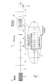
order to set up a call initiated by a third party. The paging procedure is illustrated in
figure 1. An idle mode UE is switched on and registered to the network but has no
permanent connection to it. Once registered in the network, each UE is allocated to a
paging group, which is characterised by its paging indicator PI 101. In idle mode, the
UEs periodically monitor the PICH 100, where the status (active/non active) of the
different paging indicators is signalled. When a specific paging indicator is activated,
it triggers all UEs in the cell which belong to the corresponding paging group to read
the Paging Channel (PCH) and check the validity of the paging message received on
the PICH and if the page was intended for the complete paging group (general
paging) or for the particular UE.
-
In more detail, each paging group is uniquely defined by two parameters. The first
parameter is the paging occasion 102, which specifies the time instants when the
UEs belonging to a specific paging group should read the PICH. The second is the
paging indicator identifier, which identifies the indicator 101 associated with the
paging group of interest within the paging occasion frame 102.
-
The positions of the paging occasions are defined in 3GPP TS 25.304v5.4.0 "User
Equipment (UE) procedures in idle mode and procedures for cell reselection in
connected mode" as follows:
Paging Occasions = IMSI mod DRX cycle length + n * DRX cycle length,
where IMSI is the globally unique UE identification number and n is a positive integer.
Equation 1 indicates for each UE the system frame numbers of its paging occasions.
The system frame numbering (SFN) 103 is a cyclic running time counter used to
identify the transmitted frames over time. The SFN can assume values between 0
and 4095. Each frame 102, 104-112 has a length of 10ms. A definition of SFN can be
found in 3GPP TS 25.402v5.3.0 "Synchronisation in UTRAN Stage 2". Moreover, the
time is divided, for paging purposes, into DRX cycles 113 (Discontinuous Reception),
which regroup a fixed number of frames (DRX cycle length), here 102 and 106 to
111. In 3GPP, a DRX cycle 113 is a network configured parameter and may vary
between 8 frames (0.08s) and 512 frames (5.12s). Once per DRX cycle 113, each
UE wakes up at the frame 102 corresponding to its paging occasion and monitors the
paging indicator of interest 101 that is transmitted over the PICH 100.
-
The paging indicator identifier related to a specific paging group depends also on the
UE identifier IMSI as follows (from 3GPP TS 25.304v5.4.0, cited above):
PI_identifier = (IMSI div 8192) mod N p ,
where Np = (18, 36, 72, 144) is the number of paging indicators per PICH frame as
defined in 3GPP TS 25.211v5.5.0 "Physical channels and mapping of transport
channels onto physical channels".
-
If the paging indicator PI 101 corresponding to the paging indicator identifier of the
UE paging group is activated during one of the paging occasion frames of the UE
paging group, the UE reads the PCH (paging channel).
-
The physical channel PICH structure is specified in 3GPP TS 25.211v5.5.0. One
frame 200 has a length of 10 ms and is subdivided in 300
bits 201, 202 as shown in
Figure 2. The last 12
bits 202 are unused and reserved for further usage. The first
288
bits 201 are subdivided in Np paging indicators where Np is configured by the
network. The paging indicators PI are further mapped on paging locations q
depending on the SFN in order to combat time-localised interference as shown in the
following equation.
-
Depending on Np, each PI has a length L varying between 2 consecutive bits
(Np=144) and 16 consecutive bits (Np=18). When a PI is activated, all corresponding
L bits are set to 1. They are set to 0 otherwise.
-
The performance of the paging procedure is measured by two metrics: the probability
of missed event Pm and the probability of false alarm Pf. A missed event occurs when
the UE fails to detect a paging message because of decoding errors due to an
unreliable interface between the transmitter and the receiver A false alarm occurs
when the paging decision derived by the UE is positive although this UE was not
actually paged. This generally happens since several UEs share the same paging
group. A false alarm can be caused by an unreliable interface.
-
The performance of the paging procedure is strongly influenced by 3 factors: the
PICH transmission power, the number of paging indicators per frame Np and the DRX
cycle length. The first two factors have a particularly strong influence on the
probability of missed event Pm (the probability of missing a page), whereas the last
two impact mainly the probability of a false alarm Pf (the probability of decoding an
active page although no dedicated page has been sent). At a fixed PICH
transmission power, the probability Pm is much higher when Np is set to an high value
(e.g. 144) than with a lower Np value (e.g 18). The exact value depends, of course,
on the UE receiver performance. This aspect will not be further discussed, but it can
be kept in mind that a low Np value implies a lower Pm. Unfortunately, this parameter
has an opposite effect on the probability of false alarm, and a trade-off is necessary
between Pf and Pm. Indeed, assuming a perfect reception, the probability of false
alarm is depending on the inverse of the total number of the paging groups, which is
given by the following formula:
Total number of paging groups = N P * DRX cycle length
-
Some typical values for the probability of false alarm can be found in the right column
of Table 1 further below.
-
With UMTS, a new aspect has been brought into the field of paging with the
introduction of Multimedia Broadcast Multicast Service (MBMS).
-
In MBMS, a service (video clip, data download, etc.) is broadcast over a predefined
service area and is received simultaneously by one or many mobiles that have
previously subscribed to this service. An overview of the architecture and functional
aspects of MBMS can is given in 3GPP TS 23.246v6.2.0 "Architecture and functional
description", and the radio aspects of MBMS are currently standardised in 3GPP TS
25.346v6.0.0 "Introduction of the Multimedia Broadcast Multicast Service (MBMS) in
the Radio Access Network (RAN) stage 2". The main purpose of MBMS is to allow
transmission of the same information to several mobiles at the same time (point to
multipoint transmission PtM). Therefore the network does not need to set up
dedicated links to each of the interested mobiles in order to transmit this data. Three
new channels are currently standardised by 3GPP in order to introduce MBMS
services into the UMTS system. The MTCH (MBMS Traffic Channel) is foreseen for
carrying the MBMS data content itself to several UEs within one cell during a PtM
transmission. If only a few UEs are interested in the broadcast service, the network
may rely on normal DPCH channels after establishment of separate dedicated radio
links (Point-to-point transmission PtP). Finally, two control channels are introduced.
The MCCH (MBMS Control Channel) is broadcasting the current MBMS
configuration, signals MBMS specific parameters or messages. The MICH (MBMS
indicator channel) is used for UE notification purpose.
-
One of the necessary functionalities to support MBMS is the MBMS notification
procedure, with which the network informs the UEs interested in a specific service on
the imminence of the transmission and signals the necessary configuration
parameters. The main design criteria for this functionality are UE battery
consumption, the robustness of the signalling against all kinds of perturbation and a
low probability of false alarm. Unfortunately, these design targets might contradict
each other, and typically a trade-off is needed between UE battery consumption and
the probability of false alarm. For instance, UEs which have joined one or more
MBMS services need to run a background process which periodically monitors the
MICH. Frequent MICH readings might decrease the probability of false alarm,
improve the signalling robustness and decrease the notification delay time, but would
severely impact the UE power consumption.
-
For MBMS, the current working assumption, as presented in 3GPP TS 25.346v6.0.0,
cited above, is to reuse the paging procedure as much as possible. Each MBMS
service is mapped onto an MBMS service group depending on its MBMS service
identifier like an UE is mapped onto a paging group depending on its UE identifier
(ISIM). An MBMS service group is characterised by its notification identifier, which is
mirroring the paging indicator identifier concept. The mapping function between
MBMS service identifiers and notification identifier of the corresponding MBMS
service group has not been specified and no concrete proposal has been made up to
now, but a mapping function similar to the one presented in Equation 2 will be
certainly used if finally specified. The number of different MBMS service identifiers
currently envisaged is 224, whereas the number of different MBMS service groups
depends on the notification procedure that will be standardised. It is, however, not
certain that an MBMS service group concept will be standardised as some proposals
presented in 3GPP in R1-040536 "False Alarm on MICH", 3GPP TSG RAN1 Meeting
#37 (Qualcomm) do not require this concept.
-
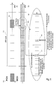
Furthermore, a new MBMS indicator channel (MICH) 300 as shown in Figure 3 is
introduced and reuses the same frame structure as the PICH 100. It contains Nni
MBMS notification indicators NI per frame, and its value may be different to the
number of paging indicators Np carried per frame by the PICH. Each notification
identifier of each MBMS service group is associated with a notification indicator NI
301 within the MICH frame. Depending on Nni, each NI is constituted L bits, where L
varies between 2 bits (Np=144) and 16 bits (Np=18). When a NI is activated, all
corresponding L bits are set to 1. They are set to 0 otherwise. The MICH frames are
further regrouped into Modification Periods 302, which should have a length at least
as long as the longest DRX cycle considered in the cell. The notified MBMS service
groups are the same over a modification period, and the MBMS UEs monitoring the
notified MBMS service groups shall read the information broadcast over the MCCH at
the next modification period.
-
The main difference with respect to the paging procedure is that there is no paging
occasion concept in MBMS, since an MBMS service notification is signalled over all
the frames forming a modification period. This is performed in order to reach all idle
mode UEs in the cell. It is currently not specified when an idle mode UE should read
the MICH but one possible solution would be to check the MICH at the paging
occasion 102 defined by the paging procedure, as the UE has to monitor the PICH in
any case for normal paging procedure as shown in figure 3. This would lead to power
saving, as paging and MBMS notification would require only one receiver activation
per DRX cycle.
-
Because of the absence of the time multiplexing between MBMS service groups
realized by the paging occasions in the case of the standard paging procedure, the
total number of MBMS service groups is significantly lower than the number of
paging groups. The total number of MBMS service groups is straightforward to derive
and equals to N
ni. As for the paging procedure, the MBMS service group size
influences the probability of false alarm P
f and the probability P
m of missing a
notification. In order to guarantee a low P
m, N
ni should be set to a low value. This
would however have a negative impact on P
f. Thus, since the loss of the time
separation cannot be compensated by a higher number of notification indicators, the
probability of false alarm for MBMS is significantly higher than for the pagingprocedure, as shown in column 2 of Table 1.
| Probalitites of false alarm Pf for MBMS notification with K=2 |
| Np | Current working assumption | Indicator combination method K=2 | Indicator sequence method K=2 | Paging procedure false alarm DRX cycle length = 1.28s 1 paged UE per paging occasion Uniform distribution of UE Id (IMSI) |
| 18 | 5,6% | 0,6% | 0,3% | 0,04% |
| 36 | 2,8% | 0,2% | 0,08% | 0,02% |
-
Two main proposals are currently considered within 3GPP in order to lower the
probability of false alarm on the MICH. The first one has been proposed by Samsung
in R1-040520 "Reducing the false alarm probability on MICH decoding", 3GPP TSG
RAN1 Meeting #37 (Samsung), where a MBMS service group is identified by a
particular combination of K notification indicator identifiers signalled by the
corresponding notification indicators within one MICH frame. The second proposal
from Qualcomm suggests mapping directly each MBMS service identifier onto a
sequence of notification indicator identifiers signalled by the corresponding
notification indicators over the successive frames composing a modification period
(see 3GPP R1-040536 cited above). With this method, a single notification indicator
identifier is signalled per frame. From this sequence, the UE reads K indicators in
order to decide whether an MBMS service is notified.
-
Herein below, this first method will be called "indicator combination method" and the
latter one will be called "indicator sequence method".
-
It is straightforward to notice that both proposals rely on a multi-component message
to signal a notification (several notification indicators are used) and not on a single
element message (one notification indicator) anymore. The main difference between
the proposals is that the indicator combination method uses notification indicator
identifiers of the same frame whereas the indicator sequence method considers
notification indicators that are spread over several frames. Moreover it should be
highlighted that with 3GPP R1-040536 (indicator sequence method), MBMS services
are directly notified and the intermediate stage of mapping the MBMS service onto
MBMS service group does not exist anymore.
-
The proposal of 3GPP R1-040520 to map each MBMS service group onto a
combination of notification indicator identifiers within the same frame (indicator
combination method) has the benefit of increasing the size of the MBMS service
group and therefore decreasing the probability of false alarm.
The number of the MBMS service groups is given by the following formula:
where K denotes the number of considered notification indicators for one MBMS
service group within one frame.
-
With Nni=18 and K=2, the number of MBMS service groups is 153.
-
It is straightforward to realize that, by the essence of the proposal itself, the UE
needs to read the K notifications indicators in order to evaluate whether the
monitored MBMS service group is notified or not. Depending on the UE
implementation of this function, it might be necessary for the UE to switch its receiver
K times during the monitored MICH frame. This might have a serious effect on the
UE battery lifetime, as switching on and off a UE receiver frequently is rather power
consuming.
-
In 3GPP R1-040536, Qualcomm proposed to directly map each MBMS service
identifier into a notification indicator identifier sequence transmitted over the
modification period (indicator sequence method). From this sequence, K notification
indicators are read by the UE. This is shown in figure 4. In the example shown in
figure 4, K equals 2. Starting with the UE paging occasion 102, the UE reads two
notification indicators 401, 402 within frames 403, 404 of MICH 300. If both
notification indicators 402, 402 are positive, a notification of the corresponding MBMS
service identifier is assumed to be present, and information is received from the
MCCH about the cause of the notification.
-
With this method, the number of the MBMS service identifiers which can be
distinguished depends on the number of notification indicators read by the UE. This
is given by the following formula:
MBMS dist_service = N ni K ,
where K denotes the number of the read notification indicators of the notification
sequence.
-
In a sense, the number of distinguishable MBMS services is similar to the number of
MBMS service groups as they have the same influence on false alarm probability.
-
With Nni =18 and K=2, the number of the distinguishable MBMS service is 324, which
is significantly higher than with the indicator combination method.
-
From an implementation point of view, 3GPP R1-040536 recommends to read a
block of K indicators before making a decision on the MBMS service notification as
shown in Figure 4. This would cause the UE receiver to stay on significantly longer
compared with the current working assumption and therefore would severely
decrease the battery lifetime.
-
In the co-pending European Patent Application ... , an alternative solution for the
enhancement of the notification procedure is proposed. In this document it is
recommended to identify the notified entity (MBMS service group or directly the
MBMS service identifier) by a set of K coordinates, which are periodically signalled
over the MICH.
-
The problem to be solved is to provide a notification mechanism based on a MICH
structure that would guarantee a low UE battery power consumption and low
probabilities of missed notification and false alarm. As highlighted earlier, the MICH
transmission power and the length of the notification indicators mainly drive the
probability of missed event and this aspect will not be treated here. The probability of
false alarm depends strongly on how the MBMS service identifier is mapped on a
single notification indicator identifier or a set of notification indicator identifier. This
aspect will not be discussed further in the context of this invention and is the object of
co-pending European Patent Application "Cyclic transmission of notification
coordinates in a communication system", by the same inventor and applicant, filed at
the same date (our docket number... ). The present invention focuses on the power
consumption aspect of the notification procedures based multiple notification
indicators, as all methods described earlier in this document require to read K
indicators every DRX cycle. This behaviour has a detrimental impact on the overall
battery lifetime.
-
It is the object of the present invention to provide a power saving method for
detecting notifications in a communication device, in particular for the case that each
notification identifier (device identifier, service identifier or service group identifier) is
associated with a sequence of notification indicator identifiers.
-
This object is achieved by a method according to claim 1, a communication device
according to claim 9, a computer-readable medium according to claim 12 and a
communication system according to claim 13.
-
The power consumption of the communication device is reduced by successively
receiving a finite set of notification indicators from a communication network, which in
combination represents a notification identifier associated with the receiving device;
subsequently checking each received notification indicator whether it is positive or
negative; determining, after each checked notification indicator and based on the
checked notification indicators, whether to proceed with the next notification indicator
or to decide on a presence of a notification for said predetermined notification
identifier; and, if it is determined that a decision is to be made, interrupting the
checking of notification indicators before all notification indicators of the set have
been checked and deciding, based on the checked notification indicators, whether a
notification for said predetermined notification identifier is assumed to be present or
not.
-
The presented method reduces the power consumption of the communication device
without undue additional cost or trade-off for reliability.
-
The accompanying drawings are incorporated into and form a part of the
specification for the purpose of explaining the principles of the invention. The
drawings are not to be construed as limiting the invention to only the illustrated and
described examples of how the invention can be made and used. Further features
and advantages will become apparent from the following and more particular
description of the invention, as illustrated in the accompanying drawings, wherein
- Figure 1 illustrates an example of a paging procedure as defined in 3GPP
- Figure 2 shows an exemplary structure of a paging indicator channel as defined in
3GPP,
- Figure 3 shows an example for a notification procedure for a Multimedia Broadcast
Multicast Service as specified by 3GPP,
- Figure 4 shows another example for a MBMS notification procedure according to an
indicator sequence method,
- Figure 5 shows how the present invention can be applied to a notification procedure
as depicted in figure 4,
- Figure 6 depicts a flow chart for a step-by-step reading according to one embodiment
of the invention,
- Figure 7 illustrates a flow chart for a step-by-step reading of a notification sequence
for reduced power consumption according to another embodiment of the invention,
- Figure 8 shows an advantageous method for defining a start occasion of a
notification detection according to a sequence based method.
- Figure 9 shows an exemplary structure of a communication device.
-
-
Referring now to figure 5 and 6, the idea of the invention is explained in detail for the
example of the indicator sequence method. In this example, K again equals 2,
although the invention could be applied without restriction to any greater value.
Indeed, the power saving increases significantly for increasing K. At the UE paging
occasion 102, the UE reads the notification indicator 501 from frame 503
corresponding to the MBMS service identifier with step 61. The UE may read
notification indicator identifiers in any order. Therefore there is no requirement to start
at a certain frame, and the most appropriate frame from power saving point of view is
chosen. Notification indicator 501 is identified by a notification indicator identifier.
This corresponding identifier is comprised in a sequence of notification indicator
identifiers associated with a notification identifier. The notification identifier in turn
may be a service identifier or a service group identifier of a service subscribed by the
UE or, in other applications, an identifier of the UE itself. In any case this notification
identifier is associated in some way with the UE meaning that the corresponding
notification is relevant for the UE. The UE now checks the contents of indicator 501 in
step 62 and determines whether a decision about the presence of a notification can
already be made or not. In the case that the indicator 501 is negative, it is determined
in step 63 that a decision can be made, the checking of further indicators is
interrupted, and it is decided that a notification is assumed not to be present. In the
case that indicator 501 is positive, the probabilities for both alternatives are too
similar, and it is checked in step 64 whether the sequence has reached its end. In the
example of figure 2, K equals 2, and one more indicator is available. Steps 61 and 62
are repeated to read and check the next indicator 502 of the sequence in the
subsequent frame. If indicator 502 is negative, it is determined in step 63 that no
notification is assumed to be present. If indicator 502 is positive, step 64 states that
the sequence has been complete read and checked and decides that a notification is
assumed to be present (although it might be false alarm due to the co-existence of
two other notifications). As a consequence, information about the cause of the
notification is obtained from another channel, like for example the MCCH, in step 65.
Any false alarm could then be discovered from this information.
-
In another alternative of the invention, the notification detection can be interrupted
advantageously without receiving a negative indicator, if a sufficient number of
positive indicators have been received so that the presence of a notification can be
assumed with sufficiently high probability. This alternative yields further reduction of
power consumption. It can be implemented alone or advantageously in combination
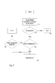
with the alternative described above. This implementation is illustrated in figure 7.
Steps 71 to 75 correspond to steps 61 to 65 of figure 6. In the case that the checked
indicator is positive and the end of the sequence has not yet been reached, there is
another decision in box 76 whether a sufficient number of positive indicators has
already been checked to assume with sufficient probability that a notification is
present. The criterion for this is determined by the UE, although it may rely on
information received from the network. One straightforward possibility would be to
check a fixed number of indicators depending on the length of the sequence.
However, as the risk of false alarm depends on the traffic payload on the MICH, this
could be influencing the criterion in a way that more indicators are checked with a
high traffic payload on the MICH, and a positive decision is made after fewer
indicators have been checked in the case that there are only few notifications present
in total on the MICH. One way to obtain information about the traffic payload of the
MICH would be to calculate the fraction of positive indicators among all indicators on
the MICH or the fraction of positive indicators among all received indicators. Another
alternative with less effort and therefore less power consumption for the UE would be
to obtain this information by means of a broadcast message from the entity which
manages the content of the MICH. A further possibility is to maintain a record of false
alarms per time unit, observed by the receiving device in the past. This value of false
alarms per time unit could also serve as a value influencing the probability of a false
alarm.
-
The described procedures will save UE power compared to the original proposals
and thus extent the battery lifetime. The same enhancement is possible in case of an
intra-frame combination of notification indicators, but there might be a lower impact
on the UE power consumption. The indicators might be consecutive or located close
together and therefore it might not be very power consuming to keep the receiver
switched on for a longer period in order read all indicators.
-
As explained above, in the case of MBMS notification, information about the cause of
the notification should be received in the modification period following the notification.
As can be seen in figure 3, it can be disadvantageous to start with the detection of
the notification at the time of the UE paging location, if this time is closer to the end of
the modification period than the number of indicators to be checked, because the
notification detection might not be finished before the start of the next modification
period, and the state of the notification might be opposite in the next modification
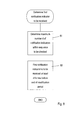
period rendering a proper detection impossible. Therefore, according to another
alternative of this invention, a start occasion for the detection with respect to the
modification period is determined like shown in figure 8. First, the number of
indicators d to be checked for the detection of a notification is determined in step 81.
This could either be the length of the indicator sequence or a number determined as
criterion for box 76 of figure 7. In box 82 the start occasion is defined at least d
frames before the end of the modification period. Thus it is assured that the reception
and detection is started early enough to allow to receive and check at least as many
notification indicators out of the sequence as required for a proper detection of the
notification. In other networks other time intervals than frames and modification
periods may exist. This method is applicable to all systems where the second time
interval, during which the state of all notifications is kept constant, comprise a fixed
entire number of the first time intervals containing one notification indicator each for
each sequence.
-
Figure 9 illustrates a schematic of a network device for carrying out the method
described above. Among other components not interesting in this context, the device
90 comprises notification indicator receiving means 91 like a network interface for
receiving notification indicators from a network, notification detection means 92 for
checking the received notification indicators and detecting a notification designated
for a notification identifier identifying the device itself, a service to which the device is
subscribed or which it hosts or a service group to which such a service belongs. The
device 80 further comprises determining means 93 for determining, after each
checked notification indicator and based on the checked notification indicators,
whether a decision about the presence of a notification for the mentioned notification
identifier is to be made; interrupting means 94 for interrupting the detection of the
notification before all notification bits have been received if it is determined that a
decision is to be made; and decision means 95 for deciding, based on the received
notification indicators, whether a notification for said determined notification identifier
is existing assumed to be present or not. Means 92 to 95 may be implemented in
software on a processing unit of the device 90.
-
Another embodiment of the present invention relates to the implementation of the
above described various embodiments using hardware and software. It is recognized
that the various above mentioned methods as well as the various logical blocks,
modules, circuits described above may be implemented or performed using
computing devices, as for example general purpose processors, digital signal
processors (DSP), application specific integrated circuits (ASIC), field programmable
gate arrays (FPGA) or other programmable logic devices, etc. The various
embodiments of the present invention may also be performed or embodied by a
combination of these devices.
-
Further, the various embodiments of the present invention may also be implemented
by means of software modules which are executed by a processor or directly in
hardware. Also a combination of software modules and a hardware implementation
may be possible. The software modules may be stored on any kind of computer
readable storage media, for example RAM, EPROM, EEPROM, flash memory,
registers, hard disks, CD-ROM, DVD, etc.