EP1605237A1 - Laser processing machine with a beam monitoring device and corresponding method for determining at least one characteristic of a laser beam - Google Patents
Laser processing machine with a beam monitoring device and corresponding method for determining at least one characteristic of a laser beam Download PDFInfo
- Publication number
- EP1605237A1 EP1605237A1 EP04013314A EP04013314A EP1605237A1 EP 1605237 A1 EP1605237 A1 EP 1605237A1 EP 04013314 A EP04013314 A EP 04013314A EP 04013314 A EP04013314 A EP 04013314A EP 1605237 A1 EP1605237 A1 EP 1605237A1
- Authority
- EP
- European Patent Office
- Prior art keywords
- laser
- processing machine
- laser processing
- detection element
- laser beam
- Prior art date
- Legal status (The legal status is an assumption and is not a legal conclusion. Google has not performed a legal analysis and makes no representation as to the accuracy of the status listed.)
- Ceased
Links
- 238000000034 method Methods 0.000 title claims abstract description 6
- 238000012545 processing Methods 0.000 title claims description 59
- 238000012806 monitoring device Methods 0.000 title 1
- 238000001514 detection method Methods 0.000 claims abstract description 38
- 238000003745 diagnosis Methods 0.000 claims description 22
- 238000003754 machining Methods 0.000 claims description 17
- 238000009826 distribution Methods 0.000 claims description 3
- 238000003860 storage Methods 0.000 claims description 3
- 238000003698 laser cutting Methods 0.000 description 19
- 238000011156 evaluation Methods 0.000 description 3
- 238000013461 design Methods 0.000 description 2
- 101100390736 Danio rerio fign gene Proteins 0.000 description 1
- 101100390738 Mus musculus Fign gene Proteins 0.000 description 1
- 238000005520 cutting process Methods 0.000 description 1
- 230000001419 dependent effect Effects 0.000 description 1
- 238000011161 development Methods 0.000 description 1
- 238000002405 diagnostic procedure Methods 0.000 description 1
- 230000010354 integration Effects 0.000 description 1
- 239000002184 metal Substances 0.000 description 1
- 230000005855 radiation Effects 0.000 description 1
- 238000003466 welding Methods 0.000 description 1
Images

Classifications
-
- G—PHYSICS
- G01—MEASURING; TESTING
- G01J—MEASUREMENT OF INTENSITY, VELOCITY, SPECTRAL CONTENT, POLARISATION, PHASE OR PULSE CHARACTERISTICS OF INFRARED, VISIBLE OR ULTRAVIOLET LIGHT; COLORIMETRY; RADIATION PYROMETRY
- G01J1/00—Photometry, e.g. photographic exposure meter
- G01J1/42—Photometry, e.g. photographic exposure meter using electric radiation detectors
- G01J1/4257—Photometry, e.g. photographic exposure meter using electric radiation detectors applied to monitoring the characteristics of a beam, e.g. laser beam, headlamp beam
-
- B—PERFORMING OPERATIONS; TRANSPORTING
- B23—MACHINE TOOLS; METAL-WORKING NOT OTHERWISE PROVIDED FOR
- B23K—SOLDERING OR UNSOLDERING; WELDING; CLADDING OR PLATING BY SOLDERING OR WELDING; CUTTING BY APPLYING HEAT LOCALLY, e.g. FLAME CUTTING; WORKING BY LASER BEAM
- B23K26/00—Working by laser beam, e.g. welding, cutting or boring
- B23K26/08—Devices involving relative movement between laser beam and workpiece
- B23K26/10—Devices involving relative movement between laser beam and workpiece using a fixed support, i.e. involving moving the laser beam
-
- B—PERFORMING OPERATIONS; TRANSPORTING
- B23—MACHINE TOOLS; METAL-WORKING NOT OTHERWISE PROVIDED FOR
- B23K—SOLDERING OR UNSOLDERING; WELDING; CLADDING OR PLATING BY SOLDERING OR WELDING; CUTTING BY APPLYING HEAT LOCALLY, e.g. FLAME CUTTING; WORKING BY LASER BEAM
- B23K26/00—Working by laser beam, e.g. welding, cutting or boring
- B23K26/70—Auxiliary operations or equipment
- B23K26/702—Auxiliary equipment
Landscapes
- Physics & Mathematics (AREA)
- Optics & Photonics (AREA)
- Engineering & Computer Science (AREA)
- Plasma & Fusion (AREA)
- Mechanical Engineering (AREA)
- General Physics & Mathematics (AREA)
- Spectroscopy & Molecular Physics (AREA)
- Laser Beam Processing (AREA)
Abstract
Description
Die Erfindung betrifft eine Laserbearbeitungsmaschine zum Bearbeiten von Werkstücken, mit einer Funktionseinheit und einem Funktionsantrieb, mittels dessen unter Bewegung der zugeordneten Funktionseinheit der Strahlfokus eines Laserstrahls und ein Werkstück zur Werkstückbearbeitung relativ zueinander positionierbar und/oder bewegbar sind. Die Erfindung betrifft des Weiteren ein Verfahren zur Bestimmung wenigstens eines Strahlkenndatums eines Laserstrahls an einer Laserbearbeitungsmaschine, wobei zur Strahldiagnose ein Strahlerfassungselement einer Strahldiagnosevorrichtung sowie der Laserstrahl unter bereichsweiser Erfassung des Laserstrahlquerschnittes durch das Strahlerfassungselement relativ zueinander in Strahlquerrichtung bewegt werden.The invention relates to a laser processing machine for processing of workpieces, with a functional unit and a Function drive, by means of which, under movement of the assigned Function unit of the beam focus of a laser beam and a Workpiece for workpiece machining relative to each other positionable and / or are movable. The invention further relates a method for determining at least one beam characteristic a laser beam on a laser processing machine, wherein for beam diagnosis, a beam detection element of a Beam diagnosis device and the laser beam under sectoral Detection of the laser beam cross-section through the beam detection element moved relative to each other in the beam transverse direction become.
Laserbearbeitungsmaschinen der eingangs genannten Art sind beispielsweise
als Laserschneid- oder Laserschweißmaschinen in
vielfältiger Ausführung bekannt. Beispielhaft zu nennen ist die
in EP 1 083 019 A2 offenbarte Laserschneidmaschine. Zur Werkstückbearbeitung
sind Relativbewegungen des Strahlfokus des als
Bearbeitungswerkzeug eingesetzten Laserstrahls und des zu bearbeitenden
Werkstückes auszuführen. Derartige Relativbewegungen
können beispielsweise entlang der zu bearbeitenden Werkstückoberfläche
aber auch - etwa zur Fokuslageneinstellung vor und
während der Bearbeitung - quer zu der Werkstückoberfläche gerichtet
sein. Zur Ausführung der bearbeitungsbedingten Relativbewegungen
dienen im Falle des Standes der Technik Funktionsantriebe
der Laserbearbeitungsmaschine, die in aller Regel numerisch
gesteuert sind.Laser processing machines of the type mentioned are, for example
as laser cutting or laser welding machines in
various design known. To name a few is the
Laser cutting machine disclosed in
Außerdem bekannt sind Strahldiagnosevorrichtungen, mittels derer nach dem eingangs genannten Verfahren Strahlkenndaten eines Laserstrahls an einer Laserbearbeitungsmaschine bestimmt werden. Eine entsprechende Strahldiagnosevorrichtung wird von der Firma PROMETEC GmbH, 52070 Aachen, DE unter der Bezeichnung "LASERSCOPE UFF 100" vertrieben. Druckschriftlich offenbart sind eine Strahldiagnosevorrichtung sowie ein Strahldiagnoseverfahren der vorstehenden Art in DE 199 09 595 A1.Also known are beam diagnostic devices, by means of which according to the method mentioned beam characteristics of a Laser beam to be determined on a laser processing machine. A corresponding beam diagnostic device is of the Company PROMETEC GmbH, 52070 Aachen, DE under the name "LASERSCOPE UFF 100" sold. Printed publications are a beam diagnostic device and a beam diagnostic method of the above type in DE 199 09 595 A1.
Bei den bekannten Strahldiagnosevorrichtungen handelt es sich um eigenständige Anordnungen, die selbständig funktionsfähig sind und die bei Bedarf an gleichfalls eigenständigen Laserbearbeitungsmaschinen zum Einsatz kommen.The known beam diagnostic devices are independent orders that are self-sufficient and, if necessary, also on self-contained laser processing machines be used.
Eine Vereinfachung der bestehenden Verhältnisse hat sich die vorliegende Erfindung zum Ziel gesetzt.A simplification of the existing conditions has the present invention aims.
Erfindungsgemäß gelöst wird diese Aufgabe durch die Laserbearbeitungsmaschine
nach Patentanspruch 1 sowie durch das Verfahren
nach Patentanspruch 11.This object is achieved according to the invention by the laser processing machine
according to
Im Falle der Erfindung ist demnach eine Strahldiagnosevorrichtung in eine Laserbearbeitungsmaschine integriert. Die für die Strahldiagnose erforderliche Relativbewegung des betreffenden Laserstrahls und eines Strahlerfassungselementes der Strahldiagnosevorrichtung wird mittels eines Funktionsantriebes der Laserbearbeitungsmaschine ausgeführt. Dieser Funktionsantrieb dient ansonsten zur bearbeitungsbedingten Relativbewegung des Strahlfokus des Laserstrahls und des zu bearbeitenden Werkstükkes. Für die erfindungsgemäße Doppelnutzung kommen verschiedene Funktionsantriebe in Frage, die üblicherweise an Laserbearbeitungsmaschinen vorgesehen sind. Zu fordern ist lediglich die Möglichkeit einer gesteuerten Relativbewegung von Laserstrahl und Strahlerfassungselement der Strahldiagnosevorrichtung in Strahlquerrichtung. Erfindungsgemäß entfällt die Notwendigkeit, eine Laserbearbeitungsmaschine und eine Strahldiagnosevorrichtung zur Bestimmung von Strahlkenndaten als eigenständige Einheiten vorzusehen. Insbesondere der Anschaffungsaufwand für eine Laserbearbeitungsmaschine mit der Möglichkeit einer Laserstrahldiagnose reduziert sich folglich auf eine Minimum. Die Strahldiagnose stellt im Falle der Erfindung eine der Funktionen der betreffenden Laserbearbeitungsmaschine dar.In the case of the invention is therefore a beam diagnostic device integrated into a laser processing machine. The for the Beam diagnosis required relative movement of the relevant Laser beam and a beam detection element of the beam diagnostic device is by means of a functional drive of the laser processing machine executed. This functional drive otherwise serves for the processing-related relative movement of the Beam focus of the laser beam and the workpiece to be machined. For the double use according to the invention come different Functional drives in question, usually on laser processing machines are provided. To claim is only the Possibility of controlled relative movement of laser beam and beam detection element of the beam diagnostic device in Beam cross direction. According to the invention, there is no need to a laser processing machine and a beam diagnostic device for determining beam characteristics as separate units provided. In particular, the acquisition cost for a Laser processing machine with the possibility of a laser beam diagnosis consequently reduces to a minimum. The Beam diagnosis in the case of the invention is one of the functions the relevant laser processing machine.
Besondere Ausführungsarten der Erfindung nach den Patentansprüchen
1 und 11 ergeben sich aus den abhängigen Patentansprüchen
2 bis 10.Particular embodiments of the invention according to the
Die in Patentanspruch 2 beschriebene Bauart der erfindungsgemäßen
Laserbearbeitungsmaschine zeichnet sich durch einen besonders
hohen Integrationsgrad aus. Im Falle dieser Laserbearbeitungsmaschine
werden nicht nur die mechanischen Komponenten eines
Funktionsantriebes der Laserbearbeitungsmaschine sondern
darüber hinaus auch Bestandteile der zugehörigen numerischen
Steuerung doppelt genutzt. Sowohl zur Steuerung der bearbeitungsbedingten
Relativbewegung von Laserstrahlfokus und Werkstück
als auch zur Steuerung der Relativbewegung eines Strahlerfassungselementes
der Strahldiagnosevorrichtung und des Laserstrahls
muss die Position des Laserstrahls in einem Bezugssystem
der Laserbearbeitungsmaschine definiert und bekannt
sein. An der Laserbearbeitungsmaschine nach Patentanspruch 2
werden die Positionsinformationen für beide Relativbewegungen
von ein und demselben Steuerungsbaustein bereitgestellt.The type described in
Ausweislich Patentanspruch 3 werden mittels des Funktionsantriebes
der Laserbearbeitungsmaschine in Weiterbildung der Erfindung
ein Strahlerfassungselement der Strahldiagnosevorrichtung
und der in einem noch nicht abschließend fokussierten Zustand
befindliche Laserstrahl relativ zueinander bewegt. Diese
Maßnahme bietet den Vorteil, dass das eingesetzte Strahlerfassungselement
lediglich verhältnismäßig niedrigen Temperaturen
ausgesetzt ist.As shown in
Demgegenüber wird im Falle der Maschinenbauart nach Patentanspruch
4 der abschließend fokussierte Laserstrahl erfasst. Die
benötigten Strahlkenndaten werden bei demjenigen Zustand des
Laserstrahls bestimmt, in welchem der Laserstrahl zur Werkstückbearbeitung
auf das betreffende Werkstück auftrifft. Das
Ergebnis der durchgeführten Strahldiagnose gibt folglich die an
der Bearbeitungsstelle tatsächlich herrschenden Verhältnisse
wieder. In contrast, in the case of the mechanical design according to
Zur Vermeidung von temperaturbedingten Beschädigungen des
Strahlerfassungselementes ist gemäß Patentanspruch 5 vorgesehen,
dass der Strahlquerschnitt des abschließend fokussierten
Laserstrahls von dem Strahlerfassungselement der Strahldiagnosevorrichtung
bei leistungsreduzierter Laserstrahlquelle erfasst
wird.To avoid temperature damage to the
Beam detection element is provided according to
Ausweislich Patentanspruch 6 wird im Falle einer bevorzugten
Bauart der erfindungsgemäßen Laserbearbeitungsmaschine zur
Strahldiagnose ein Funktionsantrieb verwendet, der ansonsten
einen Laserbearbeitungskopf relativ zu dem zu bearbeitenden
Werkstück bewegt. Mittels dieses Funktionsantriebes sind in einer
Vielzahl von Fällen auch mehrachsige Bewegungen ausführbar.
Entsprechend den hohen Genauigkeitsanforderungen an die Werkstückbearbeitung
ist auch bei der Strahldiagnose eine hochgenaue
Bewegung des betreffenden Laserstrahls relativ zu dem
Strahlerfassungselement der Strahldiagnosevorrichtung gewährleistet.
Gleichermaßen exakt stellt sich das Ergebnis der
Strahldiagnose dar.Proof of
Im Falle der Erfindungsbauart nach Patentanspruch 7 ist das
Strahlerfassungselement der Strahldiagnosevorrichtung zweckmäßigerweise
außerhalb des Arbeitsbereiches des Laserbearbeitungskopfes
ortsfest angeordnet. In the case of Erfindungsbauart according to
In kinematischer Umkehrung der Verhältnisse gemäß Patentanspruch
6 werden an der erfindungsgemäßen Laserbearbeitungsmaschine
nach Patentanspruch 8 die Bewegungsmöglichkeiten einer
das Werkstück bei der Bearbeitung lagernden Werkstücklagerung
zur Strahldiagnose genutzt. Ein Strahlerfassungselement der
Strahldiagnosevorrichtung wird gemeinschaftlich mit der Werkstücklagerung
relativ zu dem Laserstrahl bewegt. Diese Maßnahme
ist insoweit vorteilhaft, als sich der betreffende Laserstrahl
während der gesamten Strahldiagnose in einem einheitlichen Zustand
befindet. Zustandsänderungen, die sich bei Bewegung des
Laserstrahls etwa infolge von mit der Bewegung verbundenen Anpassungen
der Laserstrahlführung ergeben könnten, werden vermieden.In kinematic reversal of the conditions according to
Patentanspruch 9 beschreibt eine Ausführungsform der erfindungsgemäßen
Laserbearbeitungsmaschine mit einer Strahldiagnosevorrichtung,
die eine Bestimmung von in der betrieblichen
Praxis häufig benötigten Strahlkenndaten gestattet.
Ausweislich Patentanspruch 10 ist in bevorzugter Ausgestaltung
der Erfindung als Strahlerfassungselement ein Temperatursensor
vorgesehen. Anhand der Temperaturverhältnisse ist ein Rückschluss
auf eine Vielzahl von Laserstrahlmerkmalen möglich. As shown in
Nachstehend wird die Erfindung anhand stark schematisierter Darstellungen zu einem Ausführungsbeispiel näher erläutert. Es zeigen:
- Fig. 1
- eine Laserschneidmaschine mit Strahldiagnosevorrichtung bei der Werkstückbearbeitung,
- Fig. 2
- die Laserschneidmaschine nach Fig. 1 bei der Strahldiagnose und
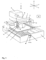
- Fig. 3
- eine Sensoranordnung der Strahldiagnosevorrichtung nach den Fign. 1 und 2.
- Fig. 1
- a laser cutting machine with beam diagnosis device for workpiece machining,
- Fig. 2
- the laser cutting machine of Fig. 1 in the beam diagnosis and
- Fig. 3
- a sensor arrangement of the beam diagnostic device according to FIGS. 1 and 2.
Ausweislich Fig. 1 besitzt eine als Laserschneidmaschine 1 ausgebildete
Laserbearbeitungsmaschine ein Maschinenbett 2, an
welchem eine Maschinenbrücke 3 in einer ersten Achsrichtung (x-Richtung)
verfahrbar geführt ist. Die Maschinenbrücke 3 lagert
ihrerseits an einem Querträger einen Führungsschlitten 4 mit
einem aufgebrochen dargestellten Laserbearbeitüngs- bzw. Laserschneidkopf
5 als Funktionseinheit. Gemeinschaftlich mit dem
Führungsschlitten 4 ist der Laserschneidkopf 5 in einer zweiten
Achsrichtung (y-Richtung) an dem Querträger der Maschinenbrücke
3 entlang verfahrbar. Darüber hinaus ist der Laserschneidkopf 5
relativ zu dem Führungsschlitten 4 in einer dritten Achsrichtung
(z-Richtung) beweglich. Unterhalb des Laserschneidkopfs 5
ist ein Werkstück in Form eines Bleches 6 auf einer im Innern
des Maschinenbettes 2 angeordneten Werkstückauflage 7 gelagert.As shown in FIG. 1 has a trained as a
Zur Bearbeitung des Bleches 6 dient ein Laserstrahl 8, der von
einer Laserstrahlquelle 9 erzeugt wird. Ausgehend von der Laserstrahlquelle
9 verläuft der Laserstrahl 8 durch ein Strahlführungsrohr
10 zu der Maschinenbrücke 3. Mittels eines dort
angebrachten ersten Umlenkspiegels 11 wird der Laserstrahl 8
parallel zu dem Querträger der Maschinenbrücke 3 zu einem zweiten
Umlenkspiegel 12 an dem Führungsschlitten 4 umgelenkt. Der
zweite Umlenkspiegel 12 reflektiert den Laserstrahl 8 zu einer
Fokussierlinse 13, welche den Laserstrahl 8 bündelt und als Bearbeitungsstrahl
auf das Blech 6 richtet. Infolge der Verfahrbarkeit
der Maschinenbrücke 3 in x-Richtung und des Führungsschlittens
4 in y-Richtung kann mit dem Laserstrahl 8 jeder beliebige
Punkt an dem Blech 6 angefahren werden. Ein in dem gezeigten
Beispielsfall an dem Blech 6 erstellter Schnitt 14 ist
in Fig. 1 angedeutet. Die Beweglichkeit des Laserschneidkopfs 5
in z-Richtung wird zur Einstellung der Fokuslage des Laserstrahls
8 in Blechquerrichtung genutzt. Eine derartige Fokuslageneinstellung
kann vor Beginn der Werkstückbearbeitung, aber
auch im laufenden Schneidbetrieb erfolgen.For processing the
Zum Bewegen des Laserschneidkopfs 5 in den drei Richtungen des
Raumes dient ein motorischer Funktionsantrieb mit einer numerischen
Steuerung 15. Mittels der numerischen Steuerung 15 werden
Antriebseinrichtungen zur Bewegung der Maschinenbrücke 3 in
x-Richtung, Antriebseinrichtungen zur Bewegung des Führungsschlittens
4 in y-Richtung sowie Antriebseinrichtungen zur Bewegung
des Laserschneidkopfs 5 in z-Richtung aufeinander abgestimmt
gesteuert. Auch die übrigen Funktionen der Laserschneidmaschine
1 sind steuerungsbezogen in die numerische Steuerung
15 integriert.For moving the
An einem Längsende des Maschinenbettes 2 ist außerhalb des Arbeitsbereiches
des Laserschneidkopfes 5 eine Sensoranordnung 17
einer Strahldiagnosevorrichtung 18 angebracht. Die Position der
Sensoranordnung 17 in dem durch die x-, die y- und die z-Achse
festgelegten Bezugssystem der Laserschneidmaschine 1 ist definiert.At one longitudinal end of the
Wie im Einzelnen aus Fig. 3 hervorgeht, umfasst die Sensoranordnung
17 eine gekühlte Lochblende 19 sowie einen darunter angeordneten
Temperatursensor 20 als Strahlerfassungselement. Der
Temperatursensor 20 steht mit einer Auswerteeinrichtung der
Strahldiagnosevorrichtung 18 in Verbindung, die ihrerseits in
die numerische Steuerung 15 der Laserschneidmaschine 1 integriert
ist. An dem Maschinenbett 2 ist die Sensoranordnung 17
in z-Richtung verstellbar. As can be seen in detail from FIG. 3, the sensor arrangement comprises
17 a cooled
Mittels der Strahldiagnosevorrichtung 18 lassen sich verschiedene
Strahlkenndaten des Laserstrahls 8 bestimmen. Zu diesen
Strahlkenndaten gehören u.a. die Strahlintensitätsverteilung im
Querschnitt des Laserstrahls 8 sowie die Lage des senkrecht
verlaufenden Abschnittes des Laserstrahls 8 bzw. der Strahlachse
16 im Raum.By means of the beam diagnostic device 18 can be different
Determine beam characteristics of the
Zur Durchführung der Strahldiagnose wird die Maschinenbrücke 3
mit dem Führungsschlitten 4 und dem Laserschneidkopf 5 mittels
des betreffenden Antriebes an das mit der Sensoranordnung 17
versehene Ende des Maschinenbettes 2 verfahren. Dort wird der
Laserschneidkopf 5 einschließlich der Fokussierlinse 13 demontiert.
Im dem sich infolgedessen ergebenden nicht abschließend
fokussierten Zustand wird der Laserstrahl 8 mittels des zweiten
Umlenkspiegels 12 an dem Führungsschlitten 4 auf die Sensoranordnung
17 gerichtet (Fig. 2).To carry out the beam diagnosis, the
Durch Verfahren der Maschinenbrücke 3 und des Führungsschlittens
4 wird der Laserstrahl 8 in x- und in y-Richtung über die
Öffnung der Lochblende 19 geführt. Der Öffnungsquerschnitt der
Lochblende 19 ist kleiner als der Querschnitt des Laserstrahls
8. Durch die Öffnung der Lochblende 19 gelangt folglich jeweils
nur ein Bereich des Strahlquerschnittes auf den Temperatursensor
20. Der Temperatursensor 20 scannt demnach den Strahlquerschnitt
des Laserstrahls 8 bereichsweise. By moving the
Mittels der Auswerteeinrichtung der Strahldiagnosevorrichtung
18 wird jedem erfassten und lagedefinierten Querschnittsbereich
des Laserstrahls 8 die dort festgestellte Temperatur zugeordnet.
Die einzelnen Querschnittsbereiche mit den jeweiligen Temperaturen
werden dann zu dem Strahl-Gesamtquerschnitt mit dem
sich über diesen einstellenden Temperaturprofil zusammengesetzt.
Auf diesem Wege wird die Strahlintensitätsverteilung im
Querschnitt des Laserstrahls 8 bestimmt.By means of the evaluation device of the beam diagnostic device
18 becomes each recorded and defined cross-sectional area
the
Durch Scannen des Laserstrahls 8 mittels des Temperatursensors
20 lässt sich von der Auswerteeinrichtung der Strahldiagnosevorrichtung
18 auch die Lage des Laserstrahlquerschnittes in
der Ebene des Temperatursensors 20 ermitteln. Wird nun die Position
der Ebene des Temperatursensors 20 durch Anheben oder
Absenken der Sensoranordnung 17 in z-Richtung verändert, so
kann durch erneutes Scannen des Laserstrahls 8 auch die Lage
des Laserstrahlquerschnittes in dieser Ebene bestimmt werden.
Die Größe des Versatzes der beiden Ebenen des Temperatursensors
20 in z-Richtung ist bekannt. Aus dem Versatz der in den beiden
Ebenen des Temperatursensors 20 erfassten Querschnitte des Laserstrahls
8 in der x- und/oder in der y-Richtung kann unter
Einbeziehung des dem Versatz der Ebenen des Temperatursensors
20 entsprechenden gegenseitigen Versatzes der Strahlquerschnitte
in z-Richtung die Lage der Strahlachse 16 im Raum bestimmt
werden. By scanning the
Genutzt werden die mittels der Strahldiagnosevorrichtung 18 gewonnenen
Erkenntnisse zur Optimierung der mit der Laserschneidmaschine
1 durchgeführten Werkstückbearbeitungen.The data obtained by the beam diagnostic device 18 are used
Findings for optimizing with the
Claims (11)
Priority Applications (3)
| Application Number | Priority Date | Filing Date | Title |
|---|---|---|---|
| DE202004021725U DE202004021725U1 (en) | 2004-06-05 | 2004-06-05 | Laser processing machine with beam diagnosis device for determining at least one beam characteristic of a laser beam on a laser processing machine |
| EP04013314A EP1605237A1 (en) | 2004-06-05 | 2004-06-05 | Laser processing machine with a beam monitoring device and corresponding method for determining at least one characteristic of a laser beam |
| US11/145,481 US20050269302A1 (en) | 2004-06-05 | 2005-06-03 | Laser machine tool with beam analyzer |
Applications Claiming Priority (1)
| Application Number | Priority Date | Filing Date | Title |
|---|---|---|---|
| EP04013314A EP1605237A1 (en) | 2004-06-05 | 2004-06-05 | Laser processing machine with a beam monitoring device and corresponding method for determining at least one characteristic of a laser beam |
Publications (1)
| Publication Number | Publication Date |
|---|---|
| EP1605237A1 true EP1605237A1 (en) | 2005-12-14 |
Family
ID=34925265
Family Applications (1)
| Application Number | Title | Priority Date | Filing Date |
|---|---|---|---|
| EP04013314A Ceased EP1605237A1 (en) | 2004-06-05 | 2004-06-05 | Laser processing machine with a beam monitoring device and corresponding method for determining at least one characteristic of a laser beam |
Country Status (3)
| Country | Link |
|---|---|
| US (1) | US20050269302A1 (en) |
| EP (1) | EP1605237A1 (en) |
| DE (1) | DE202004021725U1 (en) |
Cited By (1)
| Publication number | Priority date | Publication date | Assignee | Title |
|---|---|---|---|---|
| CN102099146A (en) * | 2008-05-02 | 2011-06-15 | 通快机床两合公司 | Device for analyzing the beam profile of a laser beam |
Families Citing this family (9)
| Publication number | Priority date | Publication date | Assignee | Title |
|---|---|---|---|---|
| DE102008027138A1 (en) * | 2008-05-30 | 2009-12-03 | Gas - Automation Gmbh | Workpiece carrier for a separating device for planar workpieces and separating device |
| DE202010016854U1 (en) | 2010-12-22 | 2011-12-29 | Anton W. HUBERT | cutter |
| JP5459255B2 (en) * | 2011-04-08 | 2014-04-02 | 株式会社安川電機 | Robot system |
| US9718148B2 (en) | 2014-08-07 | 2017-08-01 | Machitech Automation | Guiding assembly for a workpiece cutting apparatus, workpiece cutting apparatus including the same, and method for displacing a cutting assembly along a workpiece cutting table |
| CN104816090A (en) * | 2015-05-27 | 2015-08-05 | 深圳市奥斯玛数控发展有限公司 | Laser machine tool |
| JP6348149B2 (en) * | 2016-07-08 | 2018-06-27 | ファナック株式会社 | Laser processing robot system that performs laser processing using a robot |
| JP6464213B2 (en) * | 2017-02-09 | 2019-02-06 | ファナック株式会社 | Laser processing system having laser processing head and imaging device |
| CN110573292A (en) | 2017-05-05 | 2019-12-13 | 伊雷克托科学工业股份有限公司 | Multi-axis tool, control method thereof and related arrangement |
| CN107186362A (en) * | 2017-06-28 | 2017-09-22 | 惠州市柯帝士科技有限公司 | Laser cutting method |
Citations (4)
| Publication number | Priority date | Publication date | Assignee | Title |
|---|---|---|---|---|
| EP0421135A2 (en) * | 1989-10-04 | 1991-04-10 | DORRIES SCHARMANN GmbH | Method and process for determining the position and diameter of a laser beam focus, used for workpieces machining with a high power laser |
| WO1996008027A1 (en) | 1994-09-07 | 1996-03-14 | Lumonics Corporation | Focused laser beam measurement system and method of beam location |
| DE19909595A1 (en) | 1999-03-04 | 2000-09-07 | Primes Gmbh | Method for measuring spatial power density distribution of highly divergent beams by imaging captured radiation using fluorescent screen, dispersion body, integrator or detector |
| EP1083091A2 (en) | 1999-09-07 | 2001-03-14 | Fischerwerke Arthur Fischer GmbH & Co. KG | Storage compartment for a container, especially in a motor vehicle |
Family Cites Families (5)
| Publication number | Priority date | Publication date | Assignee | Title |
|---|---|---|---|---|
| US5154707A (en) * | 1987-02-27 | 1992-10-13 | Rink Dan L | Method and apparatus for external control of surgical lasers |
| DE19943043C2 (en) | 1999-09-09 | 2001-09-13 | Trumpf Gmbh & Co | Machine and method for thermal cutting, in particular for laser cutting, of workpieces |
| US6528762B2 (en) * | 2001-02-12 | 2003-03-04 | W. A. Whitney Co. | Laser beam position control apparatus for a CNC laser equipped machine tool |
| US6609545B1 (en) * | 2001-06-15 | 2003-08-26 | Ian Van Gelder | Wood cutting head structure |
| US6596961B2 (en) * | 2001-09-12 | 2003-07-22 | Fraunhofer Usa, Inc. | Method and apparatus for monitoring and adjusting a laser welding process |
-
2004
- 2004-06-05 DE DE202004021725U patent/DE202004021725U1/en not_active Expired - Lifetime
- 2004-06-05 EP EP04013314A patent/EP1605237A1/en not_active Ceased
-
2005
- 2005-06-03 US US11/145,481 patent/US20050269302A1/en not_active Abandoned
Patent Citations (4)
| Publication number | Priority date | Publication date | Assignee | Title |
|---|---|---|---|---|
| EP0421135A2 (en) * | 1989-10-04 | 1991-04-10 | DORRIES SCHARMANN GmbH | Method and process for determining the position and diameter of a laser beam focus, used for workpieces machining with a high power laser |
| WO1996008027A1 (en) | 1994-09-07 | 1996-03-14 | Lumonics Corporation | Focused laser beam measurement system and method of beam location |
| DE19909595A1 (en) | 1999-03-04 | 2000-09-07 | Primes Gmbh | Method for measuring spatial power density distribution of highly divergent beams by imaging captured radiation using fluorescent screen, dispersion body, integrator or detector |
| EP1083091A2 (en) | 1999-09-07 | 2001-03-14 | Fischerwerke Arthur Fischer GmbH & Co. KG | Storage compartment for a container, especially in a motor vehicle |
Cited By (3)
| Publication number | Priority date | Publication date | Assignee | Title |
|---|---|---|---|---|
| CN102099146A (en) * | 2008-05-02 | 2011-06-15 | 通快机床两合公司 | Device for analyzing the beam profile of a laser beam |
| US8480300B2 (en) | 2008-05-02 | 2013-07-09 | Trumpf Werkzeugmaschinen Gmbh + Co. Kg | Device for analyzing a beam profile of a laser beam |
| CN102099146B (en) * | 2008-05-02 | 2015-01-14 | 通快机床两合公司 | Device for analyzing the beam profile of a laser beam |
Also Published As
| Publication number | Publication date |
|---|---|
| DE202004021725U1 (en) | 2010-07-15 |
| US20050269302A1 (en) | 2005-12-08 |
Similar Documents
| Publication | Publication Date | Title |
|---|---|---|
| EP2284486B1 (en) | Method for measuring with a coordinate measuring device and coordinate measuring device | |
| EP3838472A1 (en) | Deflection unit with two windows, one optical element and a xy deflection device | |
| EP1133377B1 (en) | Method and device for scanning the surface of an object with a laser beam | |
| DE102011054941B3 (en) | Device useful for correcting thermal displacement of the focal position of a laser beam of a powerful laser guided to a material via optical elements for processing the material, comprises a sensor, an computing unit, and a correcting unit | |
| DE3212589A1 (en) | LASER BEAM PROCESSING MACHINE AND METHOD FOR LASER BEAM PROCESSING OF WORKPIECES | |
| DE102014113283A1 (en) | Device for remote laser processing with sensor scanner device | |
| WO2016128287A1 (en) | Multi-head laser system having a sensor unit with a movable optical guiding element | |
| EP1605237A1 (en) | Laser processing machine with a beam monitoring device and corresponding method for determining at least one characteristic of a laser beam | |
| DE102017213511A1 (en) | Process for laser material processing and laser machine | |
| DE19960017A1 (en) | Hardness tester has loading unit moved in two dimensions and calculates diagonal length of impression using image processing | |
| DE102021002040A1 (en) | Welding device and method for joining a first workpiece to a second workpiece by laser welding | |
| DE102009037593A1 (en) | Program controlled machine tool for machining workpiece, has three dimensional scanner mounted on main spindle of machine tool, and reference element permanently attached to machine tool and scannable by scanner | |
| DE10250326A1 (en) | Machine tool for alignment of the spindle position, with a correction device being used to determine the actual position of the spindle relative to reference points so that corrections can be applied | |
| DE102018217940A1 (en) | Method and processing machine for processing a workpiece | |
| EP2091699A2 (en) | Method and device for fine-positioning a tool having a handling device | |
| DE102009012543A1 (en) | cutter | |
| DE102005038587A1 (en) | Measuring system and method for laser beam has detector and beam deflecting system with controller to reflect beam onto measuring sensor | |
| DE102007019453A1 (en) | Coordinate measuring machine with two carriages on a common guide | |
| DE102021103206A1 (en) | Method for optimizing a processing time of a laser machining process, method for performing a laser machining process on a workpiece and a laser machining system set up to perform the same | |
| EP3566793B1 (en) | Slug detection for bending cells | |
| EP2648666B1 (en) | Laser arrangement, in particular for ophthalmological laser surgery | |
| EP4121247B1 (en) | Method and device for determining an actual state of support bars of a workpiece support, and machine tool having a device of this type | |
| DE102018114867A1 (en) | Process for connecting components | |
| DE102010027910A1 (en) | Rapid technology system for use in manufacture of components, has control module directing light beam emitted from laser on measuring field based on defined conditions through scanning system for providing laser power measurement | |
| EP3515627B1 (en) | Machine tool and method for machining planar workpieces |
Legal Events
| Date | Code | Title | Description |
|---|---|---|---|
| PUAI | Public reference made under article 153(3) epc to a published international application that has entered the european phase |
Free format text: ORIGINAL CODE: 0009012 |
|
| AK | Designated contracting states |
Kind code of ref document: A1 Designated state(s): AT BE BG CH CY CZ DE DK EE ES FI FR GB GR HU IE IT LI LU MC NL PL PT RO SE SI SK TR |
|
| AX | Request for extension of the european patent |
Extension state: AL HR LT LV MK |
|
| 17P | Request for examination filed |
Effective date: 20060524 |
|
| 17Q | First examination report despatched |
Effective date: 20060622 |
|
| AKX | Designation fees paid |
Designated state(s): AT BE BG CH CY CZ DE DK EE ES FI FR GB GR HU IE IT LI LU MC NL PL PT RO SE SI SK TR |
|
| 17Q | First examination report despatched |
Effective date: 20060622 |
|
| STAA | Information on the status of an ep patent application or granted ep patent |
Free format text: STATUS: THE APPLICATION HAS BEEN REFUSED |
|
| 18R | Application refused |
Effective date: 20100221 |