The subject of this invention is a detection and disconnection device
for a broken covered conductor in a medium voltage electrical
network. To be more precise this is a protection device, which
disconnects a broken covered conductor lying on the ground from
electrical power. Therefore such electrical line is safe for people and
other living beings around this area.
According to the international patent classification this invention
belongs to class H01H 83/14 and additionally to class H01H 83/12.
The technical problem being solved by the invention is such a device
construction that will enable a fast, efficient and safe disconnection of
a broken electrical line from electrical power source, fast and user-friendly
detection and localization of the broken part of the line, and
together with other equipment in the electrical network the total
reconstruction of electrical power supply; the device could be used on
existing and new electrical lines.
The author of the invention is not familiar of any similar solution of
the technical problem, which could be described as a known state of
the art...
The problem which still remained unsolved is, above all, a fast
detection of a broken electrical medium voltage line, its immediate and
reliable disconnection from electrical power source, as well as a
simple and precise localization of the broken conductor line.
According to the invention, the problem is solved with a detection and
disconnection device for a broken covered conductor in a medium
voltage electrical network. The device is constructed of an indication
unit and a disconnection unit. The disconnection unit is positioned in
front of the indication unit looking in the direction of power supply.
The information signal between the two units can be transmitted
through wired or wireless carriers. Because of different options of
power supply, we have also several different variations of the device.
The invention will be more precisely described on the basis of the
feasibility examples and figures as follows:
- Fig. 1:
- the device mounted on medium voltage power line
- Fig. 2:
- the device with a motor gear switch and autonomous power
supply, first feasible example
- Fig. 3:
- the voltage transformer charged device, second feasible
example
- Fig. 4:
- the solar charged device, third feasible example
- Fig. 5:
- the transformer station charged device, fourth feasible example
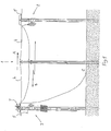
In Fig. 1, we have the detection and disconnection device for a broken
covered conductor in a medium voltage electrical network 1,
consisting of the indication unit (2) and the disconnection unit (3),
which are as a rule separately mounted on the appertain poles (6). A
disconnection device (3) is usually mounted on a pole (6) at the
beginning of covered conductors (4), whereas the indication unit (2) is
mounted at the end of covered conductors (4), as shown in Fig. 1. In
front of the disconnection unit (3) and behind the indication unit (2)
we have bar conductors (5) or some other suitable conductors. This
applies if the electrical line (1) is charged in the direction A, meaning
that the units (2) and (3) are placed on both ends of covered
conductors (4), in front of and behind bare conductors (5) and in the
above-mentioned order. As a rule, there are three bare conductors (5)
and the same number of covered conductors (4) in direction A.
If the covered conductor (4) is broken between the indication unit (2)
and the disconnection unit (3), the indication unit (2) senses the
voltage drop in one of the phases and sends information through wired
or wireless carriers to the disconnection unit (3) in direction B. The
disconnection unit (3) disconnects the line immediately from power
source through a covered conductor (4) and therefore the covered
conductor lying on the ground C is no longer a life threat. If the
disconnection does not take place, the broken covered conductor (4)
lying on the ground is hazardous to all life around. The disconnection
unit (3) disconnects the covered conductor (4) line only if the
detection unit (2) senses voltage drop or complete outage of voltage in
one or more phases. If voltage conditions on both ends of covered
conductor (4) are conserved or if they are changed in the same way in
the electrical line (1), the disconnection unit (3) does not disconnect
the line. In this case unnecessary disconnections of electrical lines (1)
have been eliminated. The indication unit (2) can be programmed in
such a way that it can send the same information to the disconnection
unit (3) and to the centre responsible for maintenance of electrical
lines. In this case the maintenance centre can easily and very quickly
fix or change the broken covered conductor (4).
Unprofessional mounting, atmospheric discharge or mechanical
damage in critical places are usually the causes for broken or thorn
covered conductors (4).
In the same way as mentioned above, the device can be used in the
case where a medium voltage line (1) is made of covered conductors
(4) only. In the case where we have bare conductors (5) only, we
cannot use this device; this applies to all feasible examples, described
in continuation.
The variation of the device according to the invention or the variation
of the indication unit (2) and disconnection unit (3) is determined by
the power supply and several different feasible examples are possible.
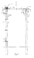
In Fig. 2 there is the first feasible example. In this example the
indication unit (2) is mounted on pole (6), between both ends of
covered conductors (4) and the beginnings of bare conductors (5). The
number of conductors 4 and 5 is optional. The indication unit (2)
consists of a voltage indicator (9) with a transmitter (13), which are
mounted on a pole (6) and of voltage transformer (14),which is
mounted on a bracket (21), and with an electrical conductor (19) joined
with corresponding covered conductors (4). Every covered conductor
(4) must have at least one voltage transformer (14). Covered
conductors (4) are connected with corresponding bare conductors (5)
through bridging bindings (20). The voltage indicator (9) is charged
directly from Lithium batteries, which are in the same housing as the
voltage indicators 9. Instead of a voltage transformer (14), we can use
a capacitive insulator (12).
On one of the poles (6) the disconnection device (3) is mounted at the
end of bare conductors (5) and at the beginning of covered conductors
(4). The disconnection unit (3), consisting of voltage indicator (9),
signal receiver (8), AC/DC charger (10), accumulator batteries (11),
voltage transformer (14) mounted on a bracket (21) and through the
electrical conductor (19) joined with covered conductors (4) and a
motor gear switch (7), that is mounted on the top of the pole (6). The
charger (10) is connected with the switch (7) by means of a cable 22.
The signal receiver (8) of the voltage indicator (9) is constructed in a
such way that it can receive wireless signals (GSM, radio wave, optical
fiber) or wired signals depending on the variation of the transmitter
(13) of the indication unit (2). The disconnection unit (3) can be
charged from many different power sources. In this example, we can
also use a capacitive insulator (12) instead of voltage transformer
(14).
In the above feasible example the device works as follows: In the case
when one of the covered conductors (4) is broken and the voltage
drops in this part of a medium voltage line (1), the voltage drop is
registered by the voltage indicator (9) in the indication unit (2). This
information is sent by the transmitter (13) in the direction B to the
signal receiver (8) and then to the voltage indicator (9) of the
disconnection unit (3). The disconnection unit (3), through the voltage
transformer (14) or through capacitive insulator (12) and switch (7),
disconnects voltage in the broken covered conductor (4). The signal
receiver (8) can be used as a transmitter, too, and can inform the
control centre about the broken voltage line (1).
In Fig. 3, there is the second feasible example in which the indication
unit (2) consists of a voltage indicator (9) with a transmitter (13) and
of an AC/DC charger (10) with an accumulator battery (11), both
mounted on a pole (6). In addition to that there is a voltage
transformer (14), which is mounted on a pole (6) with a bracket (21),
joined with the electrical line (19) and a covered conductor (4). One or
more transformers (14) can be used; they are joined with bare
conductors 5 with bridge bindings (20). In some other example we can
use a capacitive insulator (12) instead of voltage transformer (14).
The disconnection unit (3) is mounted on a pole (6) at the beginning of
covered conductors (4). The disconnection unit 3 consists of a voltage
indicator (9) with a receiver (8), an AC/DC charger (10) and an
accumulator battery (11). The above-mentioned elements are connected
with a cable (22) and the other end of the cable is connected to a
switch (7). In addition to that one or more voltage transformers (14)
are also required; they are mounted on a pole (6) with a bracket (21),
joined with the electrical line (19) and bare conductors (5). Bare
conductors (5) are joined, over a switch (7), with covered conductors
(4). Also in this example we can use a capacitive insulator (12)
instead of voltage transformer (14).
According to the second described feasible example, the device works
as follows: The voltage indicator (9) of the indication unit (2) with
help of the voltage transformer (14) senses voltage drop in the broken
covered conductor (4). This information is sent by transmitter (13) in
direction B to the signal receiver (8) with a voltage indicator (9) on
the side of the disconnection unit (3). The voltage indicator (9) with a
transmitter (13) in the indication unit (2) is charged with a charger
(10) powered by an accumulator battery (11). In the disconnection
unit (3) an AC/DC charger (10) with battery (11) charges the voltage
indicator (9) with a receiver (8).
In Fig. 4, the third feasible example according to the invention is
presented. In this example, the indication unit (2) consists of a voltage
indicator (9) with transmitter (13), solar panel (16), DC/DC charger
(18) with accumulator battery (11), and capacitive insulators (12). The
solar panel (16) is mounted on a pole (6) with a bracket (17) and
capacitive insulators (12) with the other bracket (21). All other stated
elements are mounted on a pole (6) directly or indirectly. Capacitive
insulators (12) are connected with covered conductors (4) through
electrical lines (19). Bare conductors (5) are connected with capacitive
insulators (12) with bridge bindings (20). The DC/DC charger (18)
with an accumulator battery (11) is charged with a solar panel (16). In
some other example we can use a voltage transformer (14) instead of
capacitive insulator (12.
The disconnection unit (3) mounted on a pole (6) at the beginning of
covered conductors (4) consists of voltage indicator (9) with
transmitter (13), solar panel (16), DC/DC charger (18) with
accumulator battery (11) and capacitive insulator (12). Capacitive
insulator (12) is connected to the bare conductor (5) through the
electrical line (19). Bare conductors (5) are joined with covered
conductors (4) through a switch (7).DC/DC charger 18 with
accumulator battery 11 charges the voltage indicator 9 with transmitter
13, for additional charging the solar panel 16 is used.. DC/DC charger
(18), voltage indicator (9) and switch (7) are connected with a cable
(22). Also in this example we can use a voltage transformer (14)
instead of capacitive insulator (12.
In the third feasible example the device works as follows: In the
indication unit (2), the voltage indicator 9 senses with a help of
capacitive insulators (12) a voltage drop in the broken covered
conductor (4). The transmitter (13) in the indication unit 2 sends
information in direction B to the disconnection unit (3) or precisely to
the signal receiver (8), which is simultaneously a transmitter 13 of the
voltage indicator (9). The voltage indicator (9) disconnects the broken
covered conductor (4) with help of capacitive insulators (12) with a
motor gear switch (7).
In Fig. 5, the fourth feasible example according to the invention is
shown. In this example the indication unit (2) consists of an AC/DC
charger (10) with an accumulator battery (11) and of a voltage
indicator (9) with a transmitter (13). All of them are mounted on a pole
(6), together with voltage transformer (14), which is mounted on a pole
(6) with a bracket (21). The voltage transformer (14) is connected with
a covered conductor (4) with the electrical line (19). Instead of
voltage transformer (14) we can use a capacitive insulator (12).
The disconnection unit (3) comprises AC/DC charger (10) with
accumulator battery (11), a voltage indicator (9) with a transmitter
(13) all of them mounted on a pole (6), a voltage transformer (14),
which is, over the electrical line 19, connected with the bar conductor
5. The switch (7) is mounted on the top of the pole (6). AC/DC
charger (10) and voltage indicator (9) are connected with the switch
(7) with a cable (22). Bare conductor (5) is joined with a covered
conductor (4) over the motor gear switch (7). In this case we need in
indication unit (2), as in all other above described feasible examples,
at least one voltage transformer (14) and as many capacitive insulators
(12), electrical lines (19) and bridge bindings (20) as there are covered
conductors (4) and bare conductors (5) mounted on a pole (6). The
same applies to the disconnection unit (3) with at least one voltage
transformer (14) and of which the number of capacitive insulators (12),
electrical lines (19), bridge bindings (20), poles of the switch (7) is
the same as the number of covered conductors (4) and bare conductors
(5) mounted on a pole (6).
The fifth feasible example according to the invention, which is not
shown in the figures, has its roots in the solution, that both the
indication unit (2) and the disconnection unit (3) are mounted in
transformer stations instead on the poles (6). On condition that one of
the transformer stations is at the beginning of a medium voltage line
(1) and at the beginning of the covered conductors (4), respectively
while the second transformer station is at the end of the electrical line
(1) and at the end of covered conductors (4), respectively. In this case
we can use the AC or DC power source from the transformer station.
As it is evident from previously descried feasible device examples
according to the invention, the motor drive of the motor gear switch
(7), in the executive point of the voltage line 1 and in the
disconnection unit (3), is not specified. In some other feasible example
the switch (7) can be equipped with disconnection spring, magnetic
gear or some other gear, which are not shown in the figures. It is the
rule that the signal receiver 8, placed on disconnection unit 3 side,
must be telecommunicationally harmonized with the transmitter 13 on
the side of indicator unit 2.
Totally autonomous working of the indication unit (2) and the
disconnection unit (3) can be achieved with accumulator batteries (11),
which can be charged with a solar panel (16), transformers or some
other AC or DC power source. In some other feasible example, we can
use Lithium battery or some other type of batteries, integrated in
voltage indicator (9).