EP1599832B1 - Multiple transponder seal device - Google Patents
Multiple transponder seal device Download PDFInfo
- Publication number
- EP1599832B1 EP1599832B1 EP04711382A EP04711382A EP1599832B1 EP 1599832 B1 EP1599832 B1 EP 1599832B1 EP 04711382 A EP04711382 A EP 04711382A EP 04711382 A EP04711382 A EP 04711382A EP 1599832 B1 EP1599832 B1 EP 1599832B1
- Authority
- EP
- European Patent Office
- Prior art keywords
- transponder
- seal
- electronic circuit
- seal device
- antenna
- Prior art date
- Legal status (The legal status is an assumption and is not a legal conclusion. Google has not performed a legal analysis and makes no representation as to the accuracy of the status listed.)
- Expired - Lifetime
Links
- 238000003860 storage Methods 0.000 claims abstract description 12
- 239000000758 substrate Substances 0.000 claims abstract description 12
- 238000009434 installation Methods 0.000 claims description 15
- 238000013500 data storage Methods 0.000 claims description 8
- 238000012544 monitoring process Methods 0.000 claims description 2
- 238000003780 insertion Methods 0.000 claims 1
- 230000037431 insertion Effects 0.000 claims 1
- 230000008054 signal transmission Effects 0.000 claims 1
- 238000007789 sealing Methods 0.000 description 26
- 230000005540 biological transmission Effects 0.000 description 6
- 230000006378 damage Effects 0.000 description 5
- 230000006870 function Effects 0.000 description 5
- 239000000463 material Substances 0.000 description 4
- 238000007689 inspection Methods 0.000 description 3
- 238000013475 authorization Methods 0.000 description 2
- 230000035515 penetration Effects 0.000 description 2
- 230000000717 retained effect Effects 0.000 description 2
- 238000004804 winding Methods 0.000 description 2
- 230000004913 activation Effects 0.000 description 1
- 238000004458 analytical method Methods 0.000 description 1
- 238000005520 cutting process Methods 0.000 description 1
- 230000006866 deterioration Effects 0.000 description 1
- 238000005516 engineering process Methods 0.000 description 1
- 230000010354 integration Effects 0.000 description 1
- 238000004519 manufacturing process Methods 0.000 description 1
- 239000002184 metal Substances 0.000 description 1
- 238000000034 method Methods 0.000 description 1
- 239000011824 nuclear material Substances 0.000 description 1
- 230000003287 optical effect Effects 0.000 description 1
- 230000008569 process Effects 0.000 description 1
- 230000008439 repair process Effects 0.000 description 1
- 230000004044 response Effects 0.000 description 1
- 229910052710 silicon Inorganic materials 0.000 description 1
- 239000010703 silicon Substances 0.000 description 1
- 238000011179 visual inspection Methods 0.000 description 1
- 239000002699 waste material Substances 0.000 description 1
Images


Classifications
-
- G—PHYSICS
- G09—EDUCATION; CRYPTOGRAPHY; DISPLAY; ADVERTISING; SEALS
- G09F—DISPLAYING; ADVERTISING; SIGNS; LABELS OR NAME-PLATES; SEALS
- G09F3/00—Labels, tag tickets, or similar identification or indication means; Seals; Postage or like stamps
- G09F3/02—Forms or constructions
- G09F3/03—Forms or constructions of security seals
- G09F3/0305—Forms or constructions of security seals characterised by the type of seal used
- G09F3/0317—Forms or constructions of security seals characterised by the type of seal used having bolt like sealing means
-
- B—PERFORMING OPERATIONS; TRANSPORTING
- B60—VEHICLES IN GENERAL
- B60J—WINDOWS, WINDSCREENS, NON-FIXED ROOFS, DOORS, OR SIMILAR DEVICES FOR VEHICLES; REMOVABLE EXTERNAL PROTECTIVE COVERINGS SPECIALLY ADAPTED FOR VEHICLES
- B60J10/00—Sealing arrangements
- B60J10/20—Sealing arrangements characterised by the shape
- B60J10/24—Sealing arrangements characterised by the shape having tubular parts
-
- G—PHYSICS
- G06—COMPUTING; CALCULATING OR COUNTING
- G06K—GRAPHICAL DATA READING; PRESENTATION OF DATA; RECORD CARRIERS; HANDLING RECORD CARRIERS
- G06K13/00—Conveying record carriers from one station to another, e.g. from stack to punching mechanism
- G06K13/02—Conveying record carriers from one station to another, e.g. from stack to punching mechanism the record carrier having longitudinal dimension comparable with transverse dimension, e.g. punched card
- G06K13/07—Transporting of cards between stations
- G06K13/073—Transporting of cards between stations with continuous movement
-
- G—PHYSICS
- G06—COMPUTING; CALCULATING OR COUNTING
- G06K—GRAPHICAL DATA READING; PRESENTATION OF DATA; RECORD CARRIERS; HANDLING RECORD CARRIERS
- G06K19/00—Record carriers for use with machines and with at least a part designed to carry digital markings
- G06K19/04—Record carriers for use with machines and with at least a part designed to carry digital markings characterised by the shape
- G06K19/041—Constructional details
-
- G—PHYSICS
- G06—COMPUTING; CALCULATING OR COUNTING
- G06K—GRAPHICAL DATA READING; PRESENTATION OF DATA; RECORD CARRIERS; HANDLING RECORD CARRIERS
- G06K19/00—Record carriers for use with machines and with at least a part designed to carry digital markings
- G06K19/06—Record carriers for use with machines and with at least a part designed to carry digital markings characterised by the kind of the digital marking, e.g. shape, nature, code
- G06K19/067—Record carriers with conductive marks, printed circuits or semiconductor circuit elements, e.g. credit or identity cards also with resonating or responding marks without active components
- G06K19/07—Record carriers with conductive marks, printed circuits or semiconductor circuit elements, e.g. credit or identity cards also with resonating or responding marks without active components with integrated circuit chips
- G06K19/073—Special arrangements for circuits, e.g. for protecting identification code in memory
-
- G—PHYSICS
- G06—COMPUTING; CALCULATING OR COUNTING
- G06K—GRAPHICAL DATA READING; PRESENTATION OF DATA; RECORD CARRIERS; HANDLING RECORD CARRIERS
- G06K19/00—Record carriers for use with machines and with at least a part designed to carry digital markings
- G06K19/06—Record carriers for use with machines and with at least a part designed to carry digital markings characterised by the kind of the digital marking, e.g. shape, nature, code
- G06K19/067—Record carriers with conductive marks, printed circuits or semiconductor circuit elements, e.g. credit or identity cards also with resonating or responding marks without active components
- G06K19/07—Record carriers with conductive marks, printed circuits or semiconductor circuit elements, e.g. credit or identity cards also with resonating or responding marks without active components with integrated circuit chips
- G06K19/077—Constructional details, e.g. mounting of circuits in the carrier
- G06K19/07749—Constructional details, e.g. mounting of circuits in the carrier the record carrier being capable of non-contact communication, e.g. constructional details of the antenna of a non-contact smart card
- G06K19/07758—Constructional details, e.g. mounting of circuits in the carrier the record carrier being capable of non-contact communication, e.g. constructional details of the antenna of a non-contact smart card arrangements for adhering the record carrier to further objects or living beings, functioning as an identification tag
- G06K19/0776—Constructional details, e.g. mounting of circuits in the carrier the record carrier being capable of non-contact communication, e.g. constructional details of the antenna of a non-contact smart card arrangements for adhering the record carrier to further objects or living beings, functioning as an identification tag the adhering arrangement being a layer of adhesive, so that the record carrier can function as a sticker
-
- G—PHYSICS
- G06—COMPUTING; CALCULATING OR COUNTING
- G06K—GRAPHICAL DATA READING; PRESENTATION OF DATA; RECORD CARRIERS; HANDLING RECORD CARRIERS
- G06K19/00—Record carriers for use with machines and with at least a part designed to carry digital markings
- G06K19/06—Record carriers for use with machines and with at least a part designed to carry digital markings characterised by the kind of the digital marking, e.g. shape, nature, code
- G06K19/067—Record carriers with conductive marks, printed circuits or semiconductor circuit elements, e.g. credit or identity cards also with resonating or responding marks without active components
- G06K19/07—Record carriers with conductive marks, printed circuits or semiconductor circuit elements, e.g. credit or identity cards also with resonating or responding marks without active components with integrated circuit chips
- G06K19/077—Constructional details, e.g. mounting of circuits in the carrier
- G06K19/07749—Constructional details, e.g. mounting of circuits in the carrier the record carrier being capable of non-contact communication, e.g. constructional details of the antenna of a non-contact smart card
- G06K19/07798—Constructional details, e.g. mounting of circuits in the carrier the record carrier being capable of non-contact communication, e.g. constructional details of the antenna of a non-contact smart card part of the antenna or the integrated circuit being adapted for rupturing or breaking, e.g. record carriers functioning as sealing devices for detecting not-authenticated opening of containers
-
- G—PHYSICS
- G06—COMPUTING; CALCULATING OR COUNTING
- G06K—GRAPHICAL DATA READING; PRESENTATION OF DATA; RECORD CARRIERS; HANDLING RECORD CARRIERS
- G06K7/00—Methods or arrangements for sensing record carriers, e.g. for reading patterns
- G06K7/0008—General problems related to the reading of electronic memory record carriers, independent of its reading method, e.g. power transfer
-
- G—PHYSICS
- G09—EDUCATION; CRYPTOGRAPHY; DISPLAY; ADVERTISING; SEALS
- G09F—DISPLAYING; ADVERTISING; SIGNS; LABELS OR NAME-PLATES; SEALS
- G09F3/00—Labels, tag tickets, or similar identification or indication means; Seals; Postage or like stamps
- G09F3/02—Forms or constructions
- G09F3/03—Forms or constructions of security seals
- G09F3/0305—Forms or constructions of security seals characterised by the type of seal used
- G09F3/0323—Forms or constructions of security seals characterised by the type of seal used having clamp-like sealing means
-
- G—PHYSICS
- G09—EDUCATION; CRYPTOGRAPHY; DISPLAY; ADVERTISING; SEALS
- G09F—DISPLAYING; ADVERTISING; SIGNS; LABELS OR NAME-PLATES; SEALS
- G09F3/00—Labels, tag tickets, or similar identification or indication means; Seals; Postage or like stamps
- G09F3/02—Forms or constructions
- G09F3/03—Forms or constructions of security seals
- G09F3/0305—Forms or constructions of security seals characterised by the type of seal used
- G09F3/0329—Forms or constructions of security seals characterised by the type of seal used having electronic sealing means
- G09F3/0335—Forms or constructions of security seals characterised by the type of seal used having electronic sealing means using RFID tags
-
- H—ELECTRICITY
- H05—ELECTRIC TECHNIQUES NOT OTHERWISE PROVIDED FOR
- H05K—PRINTED CIRCUITS; CASINGS OR CONSTRUCTIONAL DETAILS OF ELECTRIC APPARATUS; MANUFACTURE OF ASSEMBLAGES OF ELECTRICAL COMPONENTS
- H05K5/00—Casings, cabinets or drawers for electric apparatus
- H05K5/02—Details
- H05K5/0208—Interlock mechanisms; Means for avoiding unauthorised use or function, e.g. tamperproof
Definitions
- the present invention relates to a sealing device for closing and marking objects. More particularly, the invention relates to sealing devices that implement electronic identification means.
- seals are currently used to control the routing or storage of products or materials that have more or less important security or control requirements, such as, for example, any cargo cargo, nuclear material, certain types of waste or money.
- the function of the seal is to guarantee that the object has not been opened without authorization.
- inexpensive devices such as simple plastic or metal collars affixed to the opening members of the object, can be used. A visual inspection of the integrity of the structure of the collars is then sufficient to find that the seal was violated or not.
- a sealing device is for example known from the patent application EP 1 087 334 , which discloses a seal device comprising a first seal member, a second seal member, and means for locking the first seal member to the second seal member.
- the seal device further comprises a transponder between the two seal elements, the transponder comprising a substrate on which are formed an electronic circuit and an antenna, the electronic circuit comprising storage means for storing at least one unique identification code .
- the transponder is designed and arranged to cause the breaking of the electronic circuit or the antenna when attempting to open the seal device.
- the present invention aims to overcome the aforementioned drawbacks and to achieve a low-cost multiple-use seal device that is mechanically robust and contains information that can be consulted easily and quickly.
- the device must also allow a safe and easy control of the integrity of the seal. This objective is achieved by a seal according to claim 1, the preamble of which consists of the characteristics described in EP 1 087 334 .
- a sealing device comprising a locking pin and a socket, the locking pin comprising a head and a rod, preferably having a groove which cooperates with a locking ring disposed in the socket to lock by inserting said socket on the pin, characterized in that the socket further comprises a first transponder housed inside the socket at a depth greater than the height of the rod and in that the locking pin further comprises a second transponder disposed on the outer periphery of the rod, each transponder comprising a substrate on which are formed each time an electronic circuit and an antenna, said electronic circuit comprising storage means for storing at least one unique identification code, said second transponder being designed and arranged to cause the disruption of said electronic circuit or said antenna said second transponder during an attempt to open said seal device.
- the sealing device it is possible to mark any object with a unique identity, which allows to control and track the object during and after transport.
- the integrity of the sealing device is checked by interrogating a second transponder, which does not require any dismantling of the seal and makes it possible to check at any place the conformity of the identity information contained in the transponder.
- the socket further comprises a third transponder held inside thereof at a depth less than the height of the rod, the transponder comprising a substrate on which an electronic circuit is formed and an antenna, said electronic circuit comprising storage means for storing at least one unique identification code.
- the third transponder is held in the socket by an annular element which covers at least the antenna of said transponder.
- the first transponder may contain, in addition to a unique identification code, data relating to the date and place of installation of the seal device, or information on inspections carried out on the object during its execution. transport.
- the means of storage of the first transponder may include data encryption means.
- the subject of the invention is also a system for controlling and tracking an object, said object comprising at least one sealing device as described above, characterized in that it comprises a device for transmitting signals for reading or writing data. information in the transponders of the sealing device, processing means and data storage means for recording the information stored in the transponders.
- the installation and integrity of the seal device can be controlled by remote interrogation of the transponders without any manipulation of the device.
- the information stored in the first transponder with the exception of the identification code, can be consulted and updated in real time.
- the data storage means of the system also makes it possible to store important information, such as the identification code, to subsequently allow a comparison with the codes read on the device in order to detect any unauthorized manipulation of the device.
- the data storage means are accessible remotely via a network link. This makes it possible to carry out checks anywhere and at any time by having a remotely accessible reference on the original data associated with the sealing device.
- a code of a transponder can be read during a step of transporting the marked object with the seal device and compare the read code with that originally recorded to detect an unauthorized replacement of the sealed.
- the processing means may comprise software means for confirming the installation of the sealed device by interrogating the third transponder and / or for detecting an unauthorized manipulation of the sealed device by interrogation of the third second transponder.
- the processing means may also comprise a software means for detecting unauthorized replacement of the seal device by reading the codes of the transponders of the seal device and comparing said codes with the original codes previously recorded in the data storage means. .
- the figure 1 shows the sealed device 1 according to the invention.
- the device 1 is formed of a locking pin 10 and a socket 20 to be locked on pin 10.
- Pin 10 and socket 20 form a single-use self-locking mechanical system which is used to mark the closing of any object.
- the pin 10 comprises a head 11 and a rod 12, the rod 12 having a locking groove 13 which cooperates with a locking ring 24 held inside the sleeve 20 by means of a groove 25 which is formed in the body 21 of the sleeve.
- the device 1 can be used to mark the closing of an object by the establishment at two elements 5 and 6 of the closing system of the object in which a hole 4 is formed.
- the pin 10 is inserted into the hole 4 and retained by the head 11 which has dimensions greater than those of the hole 4.
- the bushing 20 is put in place on the rod 12 of the pin, which makes it possible to lock the elements 5 and 6 sets.
- the body 21 of the sleeve 20 may comprise a portion 22 adjusted to the dimensions of the hole 4. Therefore, once the seal device 1 installed, the object can not be opened without cutting or break the device 1 ( figure 4 ).
- the sealing device comprises several electronic components of the transponder type.
- a first transponder 30 is used as a permanent means of storing information relating to the sealing device and the object with which it is associated. The nature of this information and its use will be described in more detail below. Since the transponder 30 is a permanent transponder, it is disposed in a part of the device where it will be protected from any deterioration. For example, as shown on the figure 1 , the transponder 30 is housed in the upper part of the sleeve 20 at a depth P which is greater than the height H of the rod 12 which corresponds to the maximum penetration distance of the rod in the socket. The transponder 30 is held against a cover 23 which closes the upper part of the body 21 of the bushing 20. The transponder 30 can be glued to the cover 23.
- a second transponder 40 is disposed on the periphery of the rod 12 of the spindle 10.
- the transponder 40 can be glued to the rod 12 to hold it in place on the latter.
- a third transponder 50 is held inside the bushing 20 at an intermediate depth P ', less than the height H of the rod, by a flange clamp 26 disposed between the transponder 50 and the transponder 30.
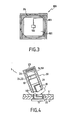
- the figure 3 illustrates the general structure of transponders 30, 40 and 50 which are used in the present invention.
- a transponder 100 is formed of a substrate 101 on which are disposed an electronic chip 102 and an antenna 103.
- the antenna 103 is formed by a coil which extends over the entire periphery of the substrate. One end of this winding is connected to the chip 102.
- the chip 102 mainly comprises an electronic data storage circuit which can be accessed in reading as well as in writing, as the case may be.
- Each transponder initially contains a unique permanent code which constitutes the identity of the transponder and which can not be modified.
- the reading, and possibly the writing, of data in the memory circuit is carried out by radiofrequency transmission thanks to the antenna 103 in particular. If the winding which constitutes the antenna 103 is interrupted, it becomes inoperative and no transmission between the chip 102 and the outside can no longer be performed, thus testifying to the damage of the component 100.
- transponder model described is passive type, ie the antenna serves not only for the transmission of data but also to receive an activation field for the supply of electrical energy to the electronic circuit of the chip. It is also possible to use transponders which comprise an autonomous power supply means, such as a battery, which battery is connected to the chip 102 to supply power.
- an autonomous power supply means such as a battery
- transponder The type of transponder described above is particularly suitable for the present invention. Indeed, such components have a very small footprint which allows them to be easily housed in sealed devices such as that of the invention.
- the substrate of the component is made of a brittle material such as silicon, it can be broken easily and thus allow the destruction of the component or at least the antenna of the latter with little resistance.
- the shape, dimensions and material of the substrate can be adapted as described below.
- a flexible material is preferably chosen which facilitates the positioning of the transponder on the rod.
- the transponder represented figure 3 has the shape of a square. However, as regards transponders 30 and 50 in particular, these could also have a circular shape to facilitate their integration into the socket.
- the permanent transponder 30 is used to store all the relevant information that will make it possible to identify the object whose closure has been marked with the sealing device of the invention.
- the object in question can be a container for transporting goods.
- the information recorded in the transponder 30 may correspond to the date and place of loading and closing of the container, the nature of the goods transported, the various customs inspections carried out, the names or the identification of the parties responsible for such inspections, ....
- the transponder 40 which is disposed on the rod 12 of the spindle 10 is used as a witness of the integrity of the sealing device. Indeed, as illustrated on the figure 4 any attempt to open the sealed object, causes the rupture of the seal device 1 and that of the transponder 40 which can not, therefore, be questioned.
- two solutions can be considered. The first is to repair the cut stem and reposition it in the seal device. The second solution is to completely replace the seal device with a new one. In both cases, unauthorized manipulation can be detected.
- the fraudulent manipulation will be detected from the next interrogation which will reveal that the transponder 40 does not respond and that, therefore, the device seal has been violated.
- the reading will reveal that the identification code of the transponder has changed and that it does not correspond to that originally recorded.
- the transponder 50 is used as a witness for the proper installation of the sealing device. Indeed, as illustrated on the figure 1 , the transponder 50 is held inside the bushing 20 at a depth P 'which is less than the height H of the rod 12 of the spindle 10 corresponding to the penetration distance of the rod into the bushing. Therefore, as illustrated on the Figure 5A when inserting the bushing 20 on the spindle 10, the end 14 of the rod 12 will abut on the transponder 50. Consequently, to bring the bushing to its final position, that is to say in the position where the ring 24 is blocked in the groove 13 of the rod, it will break the transponder 50.
- the transponder 50 is in two pieces 50A and 50B.
- the piece 50A corresponds to the part of the transponder which has been detached by the rod 12 while the piece 50B corresponds to the part which is retained between the body of the sleeve 21 and the strut holder 26. It must be ensured that the 26 which holds the piece 50A of the transponder 50 covers at least a sufficient portion of the transponder to ensure the destruction of the transponder.
- the flange 26 covers at least a portion of the antenna 103 to ensure the rupture of the latter during the installation of the device.
- the transponder 50 responds to a remote interrogation, it means that it is intact and that the bushing is not correctly positioned on the spindle.
- the reading and / or recording of data in the transponders can be carried out for example by means of a radiofrequency transmission device 60 represented in FIG. figure 2 .
- the transmission between the device 60 and the transponders is effected by radiofrequency signals RFin and RFout which respectively correspond to the signals received and to the signals sent by the device 60.
- radiofrequency signals RFin and RFout which respectively correspond to the signals received and to the signals sent by the device 60.
- the device 60 may be a portable reader that makes it possible to read and write data in a transponder.
- a reader comprises a display screen 61, a keyboard 62 and / or storage means of the interrogated data.
- the reader activates the radio frequency (RF) transponder, for example at a frequency of 13.56 MHz.
- RF radio frequency
- This wave charges a capacitance present in the circuit of the transponder. When the latter discharges, it sends back to the reader a code or information, stored in the transponder memory.
- This type of portable reader makes it possible to exchange data with the transponders over a distance of about 30 cm.
- each interrogated transponder is thus sent to the device 60.
- these data can be displayed on its screen 61 and / or stored in its memory.
- the device 60 may also include integrated processing means specially programmed to perform the checks described herein.
- processing means such as a computer 70, may be used to process the transponder data.
- the computer is connected to the device 60, via a serial link 67, to be able to exchange data with each transponder memory.
- the processing means comprise and execute software that makes it possible to perform all kinds of control and monitoring functions from the transponder data.
- the device 60 or the computer 70 may comprise software means for initially controlling the installation of the device by interrogating the transponder 50.
- the breaking information of the transponder 50 which therefore testifies to the installation correct sealing device, can be used as starting information by the processing means for, for example, store the identification codes of one or more transponders for future checks.
- the software can also make it possible to establish the correlation between the identification number of one of the transponders and various data such as the place, and / or the name of the inspector who installed the seal, and / or the date of installation of the seal.
- the software can also be used to write or update data in transponders (with the exception of the identification code which can not be modified).
- Information such as identification codes
- a database 80 ( figure 2 ) which can be accessed online, via a network link 78 such as an Internet link for example.
- the transmitting device 60, the computer 70 and the database 80 constitute a system which makes it possible to control and follow in real time any object which is marked by one or more sealing devices of the invention. This allows a tracking and a control of the goods throughout its transport. The integrity of the device can be controlled at any time. Indeed, the interrogation of the transponder 40 makes it possible to determine in a first time whether the latter is intact and, if necessary, to compare the code read in the latter with the code originally recorded in the database 80 which can be accessed remotely via network link 78.
- the permanent transponder 30 which can contain all kinds of information enriched during the steps of the transport of the object, thus constitutes the history of the seal device which can be accessed in real time by interrogating the transponder 30 at a location control.
- the sealing device according to the invention fulfills the same requirements. Its applications can be multiple.
- a plurality of devices 1 are used to mark the closing of a lid 2 on an enclosure 3.
- the elements 5 and 6 correspond to flanges in which passage openings of the devices 1 are provided. The integrity of the system thus formed is guaranteed and can be easily controlled as described above.
- the seal according to the invention has the following advantages.
- the installation of the sealing device can be validated by interrogating a transponder.
- the sealed object and its goods can be tracked throughout the transport by transponder interrogation and transmission of information. Indeed, the information, such as identification codes, can be read as many times as necessary since this is done without dismantling or tampering with the sealed device and, therefore, without compromising its integrity.
- the integrity of the device can be checked anywhere, either directly when the transponder is no longer responding, or by comparison with the identification code (s) read on site and compared with those originally recorded in an accessible database. online when the device has been replaced without authorization. It is then possible, by analysis of the data recorded in the permanent transponder, to possibly determine the person responsible, the place and the date of the unauthorized manipulation.
- the transponder circuit comprises programmable or encryptable means, it is possible to encode or encrypt the data stored in the seal, resulting in an increased level of security.
- the sealing device has a low manufacturing cost.
- the seal device has a good mechanical robustness that allows it to be used with transport objects such as containers that are often handled without special precautions.
Landscapes
- Engineering & Computer Science (AREA)
- Physics & Mathematics (AREA)
- General Physics & Mathematics (AREA)
- Theoretical Computer Science (AREA)
- Microelectronics & Electronic Packaging (AREA)
- Computer Hardware Design (AREA)
- Computer Security & Cryptography (AREA)
- General Engineering & Computer Science (AREA)
- Computer Vision & Pattern Recognition (AREA)
- Artificial Intelligence (AREA)
- Mechanical Engineering (AREA)
- Radar Systems Or Details Thereof (AREA)
- Details Of Aerials (AREA)
- Details Of Rigid Or Semi-Rigid Containers (AREA)
- Burglar Alarm Systems (AREA)
- Arrangements For Transmission Of Measured Signals (AREA)
- Seal Device For Vehicle (AREA)
- Gasket Seals (AREA)
Abstract
Description
La présente invention concerne un dispositif de scellé pour fermer et marquer des objets. Plus particulièrement, l'invention se rapporte aux dispositifs de scellé qui mettent en oeuvre des moyens électroniques d'identification.The present invention relates to a sealing device for closing and marking objects. More particularly, the invention relates to sealing devices that implement electronic identification means.
De nombreux types de scellés sont actuellement utilisés pour contrôler le cheminement ou le stockage de produits ou matériels qui présentent des besoins de sécurité ou de contrôle plus ou moins importants, comme, par exemple, des marchandises de fret quelconques, des matières nucléaires, certains types de déchets ou bien de l'argent.Many types of seals are currently used to control the routing or storage of products or materials that have more or less important security or control requirements, such as, for example, any cargo cargo, nuclear material, certain types of waste or money.
Les technologies employées pour la réalisation des scellés sont très variées et dépendent principalement de l'usage et des degrés de sécurité demandés.The technologies used for the realization of seals are very varied and depend mainly on the use and the degrees of security required.
Ainsi, lorsqu'on désire s'assurer simplement de l'intégrité d'un objet, tel qu'un sac ou un container, la fonction du scellé est de garantir que l'objet n'a pas été ouvert sans autorisation. Dans ce cas, des dispositifs peu onéreux, comme de simples colliers de plastique ou de métal apposés sur les organes d'ouverture de l'objet, peuvent être utilisés. Une inspection visuelle de l'intégrité de la structure des colliers suffit alors pour constater que le scellé a été violé ou non.Thus, when it is desired to simply ensure the integrity of an object, such as a bag or a container, the function of the seal is to guarantee that the object has not been opened without authorization. In this case, inexpensive devices, such as simple plastic or metal collars affixed to the opening members of the object, can be used. A visual inspection of the integrity of the structure of the collars is then sufficient to find that the seal was violated or not.
D'autre part, il existe de plus en plus de domaines, comme le transport international, dans lesquels les scellés doivent non seulement remplir leur fonction de base, qui est de pouvoir attester de l'inviolabilité de l'objet, mais aussi pouvoir fournir des informations pendant et après leur transport. Ainsi, il existe actuellement des dispositifs qui comprennent des moyens mécaniques de scellement auxquels sont associés des moyens électroniques ou optiques qui permettent de mémoriser et transmettre des informations.On the other hand, there are more and more areas, such as international transport, in which seals must not only fulfill their basic function, which is to be able to attest to the inviolability the object, but also to provide information during and after transport. Thus, there are currently devices that include mechanical sealing means which are associated with electronic or optical means that can store and transmit information.
Un dispositif de scellé est par exemple connu de la demande de brevet
Cependant, les dispositifs de scellé actuels qui comprennent des moyens électroniques sont complexes et coûteux. Ils sont en général conçus pour un usage spécifique et ne peuvent pas être mis en oeuvre avec n'importe quel type d'objet. De plus, ils présentent une structure mécanique fragile qui les rend très sensibles aux manipulations et aux transports ce qui restreint encore leur utilisation.However, current sealing devices that include electronic means are complex and expensive. They are usually designed for a specific purpose and can not be implemented with any type of object. In addition, they have a fragile mechanical structure that makes them very sensitive to handling and transport which further restricts their use.
La présente invention vise à remédier aux inconvénients précités et à réaliser un dispositif de scellé à usage multiple de faible coût qui est mécaniquement robuste et qui contient des informations consultables de façon simple et rapide. Le dispositif doit aussi permettre un contrôle sûr et aisé de l'intégrité du scellé. Cet objectif est atteint par un dispositif de scellé selon la revendication 1 dont le préambule est constitué par les caractéristiques décrites dans
Ces buts sont atteints grâce à un dispositif de scellé, comprenant une broche de verrouillage et une douille, la broche de verrouillage comprenant une tête et une tige, comportant de préférence une gorge qui coopère avec un anneau de blocage disposé dans la douille pour verrouiller par insertion ladite douille sur la broche, caractérisé en ce que la douille comprend en outre un premier transpondeur logé à l'intérieur de la douille à une profondeur plus grande que la hauteur de la tige et en ce que la broche de verrouillage comprend en outre un second transpondeur disposé sur la périphérie externe de la tige, chaque transpondeur comprenant un substrat sur lequel sont formés à chaque fois un circuit électronique et une antenne, ledit circuit électronique comprenant des moyens de stockage pour stocker au moins un code d'identification unique, ledit second transpondeur étant conçu et agencé de sorte à causer la rupture dudit circuit électronique ou de ladite antenne dudit second transpondeur lors d'une tentative d'ouverture dudit dispositif de scellé.These objects are achieved by means of a sealing device, comprising a locking pin and a socket, the locking pin comprising a head and a rod, preferably having a groove which cooperates with a locking ring disposed in the socket to lock by inserting said socket on the pin, characterized in that the socket further comprises a first transponder housed inside the socket at a depth greater than the height of the rod and in that the locking pin further comprises a second transponder disposed on the outer periphery of the rod, each transponder comprising a substrate on which are formed each time an electronic circuit and an antenna, said electronic circuit comprising storage means for storing at least one unique identification code, said second transponder being designed and arranged to cause the disruption of said electronic circuit or said antenna said second transponder during an attempt to open said seal device.
Ainsi, grâce au dispositif de scellé selon l'invention, il est possible de marquer tout objet avec une identité unique, ce qui permet de contrôler et de suivre l'objet pendant et après son transport. De plus, le contrôle de l'intégrité du dispositif de scellé s'effectue par interrogation d'un second transpondeur, ce qui ne nécessite aucun démontage du scellé et permet de contrôler en tout lieu la conformité des informations d'identité contenues dans le transpondeur.Thus, thanks to the sealing device according to the invention, it is possible to mark any object with a unique identity, which allows to control and track the object during and after transport. In addition, the integrity of the sealing device is checked by interrogating a second transponder, which does not require any dismantling of the seal and makes it possible to check at any place the conformity of the identity information contained in the transponder. .
Selon un aspect particulier de l'invention, la douille comprend en outre un troisième transpondeur maintenu à l'intérieur de celle-ci à une profondeur inférieure à la hauteur de la tige, le transpondeur comprenant un substrat sur lequel sont formés un circuit électronique et une antenne, ledit circuit électronique comprenant des moyens de stockage pour stocker au moins un code d'identification unique.According to a particular aspect of the invention, the socket further comprises a third transponder held inside thereof at a depth less than the height of the rod, the transponder comprising a substrate on which an electronic circuit is formed and an antenna, said electronic circuit comprising storage means for storing at least one unique identification code.
Grâce à ce troisième transpondeur placé à une profondeur intermédiaire dans la douille, il est possible de vérifier que le dispositif a été correctement installé, c'est à dire que la douille a été correctement verrouillée sur la broche rendant toute ouverture de l'objet impossible sans destruction du dispositif de scellé.With this third transponder placed at an intermediate depth in the socket, it is possible to verify that the device has been correctly installed, that is to say that the socket has been properly locked on the pin making any opening of the object impossible. without destruction of the seal device.
Pour garantir une complète destruction du troisième transpondeur lors de l'installation du dispositif de scellé, il est maintenu dans la douille par un élément annulaire qui couvre au moins l'antenne dudit transpondeur. Ainsi, lors d'une interrogation, l'absence de réponse du troisième transpondeur témoigne d'une installation correcte.To ensure complete destruction of the third transponder during the installation of the seal device, it is held in the socket by an annular element which covers at least the antenna of said transponder. Thus, during a query, the lack of response of the third transponder testifies to a correct installation.
Le premier transpondeur peut contenir, en outre d'un code d'identification unique, des données relatives à la date et au lieu de mise en place du dispositif de scellé, ou bien des informations sur des inspections réalisées sur l'objet lors de son transport. Les moyens de stockage du premier transpondeur peuvent comprendre des moyens de cryptage des données.The first transponder may contain, in addition to a unique identification code, data relating to the date and place of installation of the seal device, or information on inspections carried out on the object during its execution. transport. The means of storage of the first transponder may include data encryption means.
L'invention a également pour objet un système de contrôle et de suivi d'un objet, ledit objet comprenant au moins un dispositif de scellé comme décrit précédemment, caractérisé en ce qu'il comprend un dispositif de transmission de signaux pour lire ou écrire des informations dans les transpondeurs du dispositif de scellé, des moyens de traitement et des moyens de stockage de données pour enregistrer les informations stockées dans les transpondeurs.The subject of the invention is also a system for controlling and tracking an object, said object comprising at least one sealing device as described above, characterized in that it comprises a device for transmitting signals for reading or writing data. information in the transponders of the sealing device, processing means and data storage means for recording the information stored in the transponders.
Ainsi, grâce au système de l'invention, l'installation et l'intégrité du dispositif de scellé peuvent être contrôlées par interrogation à distance des transpondeurs sans aucune manipulation du dispositif. De plus, les informations stockées dans le premier transpondeur, à l'exception du code d'identification, peuvent être consultées et mises à jour en temps réel. Les moyens de stockage de données du système permettent en outre de mémoriser des informations importantes, comme le code d'identification, pour permettre par la suite une comparaison avec les codes lus sur le dispositif afin de détecter toute manipulation non autorisée du dispositif.Thus, thanks to the system of the invention, the installation and integrity of the seal device can be controlled by remote interrogation of the transponders without any manipulation of the device. In addition, the information stored in the first transponder, with the exception of the identification code, can be consulted and updated in real time. The data storage means of the system also makes it possible to store important information, such as the identification code, to subsequently allow a comparison with the codes read on the device in order to detect any unauthorized manipulation of the device.
Selon une caractéristique particulière, les moyens de stockage de données sont accessibles à distance via une liaison réseau. Ceci permet d'effectuer des contrôles en tout lieu et à tout moment en ayant une référence accessible à distance sur les données d'origines associées au dispositif de scellé. Par exemple, on peut lire un code d'un transpondeur lors d'une étape du transport de l'objet marqué avec le dispositif de scellé et comparer le code lu avec celui enregistré à l'origine pour détecter un remplacement non autorisé du dispositif de scellé.According to a particular characteristic, the data storage means are accessible remotely via a network link. This makes it possible to carry out checks anywhere and at any time by having a remotely accessible reference on the original data associated with the sealing device. For example, a code of a transponder can be read during a step of transporting the marked object with the seal device and compare the read code with that originally recorded to detect an unauthorized replacement of the sealed.
A cet effet, les moyens de traitement peuvent comprendre des moyens logiciels pour confirmer l'installation du dispositif de scellé par interrogation du troisième transpondeur et/ou pour détecter une manipulation non autorisée du dispositif de scellé par interrogation du deuxième transpondeur. Les moyens de traitement peuvent comprendre aussi un moyen logiciel pour détecter un remplacement non autorisé du dispositif de scellé par lecture des codes des transpondeurs du dispositif de scellé et par comparaison desdits codes avec les codes d'origine enregistrés préalablement dans les moyens de stockage de données.For this purpose, the processing means may comprise software means for confirming the installation of the sealed device by interrogating the third transponder and / or for detecting an unauthorized manipulation of the sealed device by interrogation of the third second transponder. The processing means may also comprise a software means for detecting unauthorized replacement of the seal device by reading the codes of the transponders of the seal device and comparing said codes with the original codes previously recorded in the data storage means. .
D'autres caractéristiques et avantages de l'invention ressortiront de la description suivante de modes particuliers de réalisation de l'invention, donnés à titre d'exemples non limitatifs, en référence aux dessins annexés, sur lesquels :
- la
figure 1 est une vue en perspective d'un dispositif de scellé conformément à un mode de réalisation selon l'invention, - la
figure 2 est une vue schématique d'un dispositif de scellé en position verrouillée et d'un système d'interrogation et de traitement de l'invention, - la
figure 3 est une vue schématique du type de transpondeur utilisé dans le dispositif de scellé de l'invention, - la
figure 4 est une vue schématique en coupe montrant le dispositif de scellé lors de l'ouverture d'un objet marqué avec le dispositif, - les
figures 5A et 5B montrent des étapes d'installation du dispositif de scellé selon l'invention, - la
figure 6 est une vue en perspective d'un exemple d'application de l'invention.
- the
figure 1 is a perspective view of a sealing device according to an embodiment according to the invention, - the
figure 2 is a schematic view of a seal device in the locked position and an interrogation and processing system of the invention, - the
figure 3 is a schematic view of the type of transponder used in the sealed device of the invention, - the
figure 4 is a schematic sectional view showing the sealing device when opening an object marked with the device, - the
Figures 5A and 5B show steps of installation of the sealing device according to the invention, - the
figure 6 is a perspective view of an exemplary application of the invention.
La
Par exemple, comme illustré sur la
Le dispositif de scellé selon l'invention comprend plusieurs composants électroniques de type transpondeur. Un premier transpondeur 30 est utilisé comme moyen permanent de stockage d'informations relatives au dispositif de scellé et à l'objet auquel il est associé. La nature de ces informations ainsi que leur utilisation seront décrites plus loin en détail. Puisque le transpondeur 30 est un transpondeur permanent, il est disposé dans une partie du dispositif où il sera protégé de toute détérioration. Par exemple, comme illustré sur la
Un deuxième transpondeur 40 est disposé sur la périphérie de la tige 12 de la broche 10. Le transpondeur 40 peut être collé sur la tige 12 pour le maintenir en place sur cette dernière.A
Enfin, un troisième transpondeur 50 est maintenu à l'intérieur de la douille 20 à une profondeur Intermédiaire P', inférieure à la hauteur H de la tige, par un serre-flanc 26 disposé entre le transpondeur 50 et le transpondeur 30.Finally, a
La
La lecture, et éventuellement l'écriture, de données dans le circuit de mémoire s'effectue par transmission radiofréquence grâce à l'antenne 103 notamment Si l'on interrompt le bobinage qui constitue l'antenne 103, celle-ci devient inopérante et aucune transmission entre la puce 102 et l'extérieur ne peut plus être réalisée, témoignant ainsi de l'endommagement du composant 100.The reading, and possibly the writing, of data in the memory circuit is carried out by radiofrequency transmission thanks to the
Le modèle de transpondeur décrit est de type passif, c'est à dire que l'antenne sert non seulement à la transmission des données mais aussi à recevoir un champ d'activation pour l'alimentation en énergie électrique du circuit électronique de la puce. Il est également possible d'utiliser des transpondeurs qui comprennent un moyen d'alimentation autonome, telle qu'une batterie, celle-ci étant reliée à la puce 102 pour l'alimenter en énergie.The transponder model described is passive type, ie the antenna serves not only for the transmission of data but also to receive an activation field for the supply of electrical energy to the electronic circuit of the chip. It is also possible to use transponders which comprise an autonomous power supply means, such as a battery, which battery is connected to the
Le type de transpondeur décrit ci-dessus est particulièrement adapté pour la présente invention. En effet, de tels composants présentent un encombrement très réduit ce qui permet de les loger facilement dans des dispositifs de scellé comme celui de l'invention. De plus, le substrat du composant étant en une matière fragile telle que du silicium, il peut être brisé facilement et permettre ainsi la destruction du composant ou au moins de l'antenne de ce dernier avec peu de résistance. Toutefois, suivant sa fonction dans le dispositif de l'invention, la forme, les dimensions et le matériau du substrat pourront être adaptés comme décrit ci-après. Par exemple, pour le substrat du transpondeur 40 qui est destiné à être placé sur la périphérie de la tige 12, on choisit de préférence un matériau souple qui facilite la mise en place du transpondeur sur la tige. De plus, le transpondeur représenté en
On décrit maintenant plus en détail, les différentes fonctions des transpondeurs qui sont utilisés dans le dispositif de scellé de l'invention.The different functions of the transponders used in the sealing device of the invention will now be described in greater detail.
Le transpondeur permanent 30 est utilisé pour stocker toutes les informations pertinentes qui vont permettre d'identifier l'objet dont la fermeture a été marquée avec le dispositif de scellé de l'invention. A titre d'exemple, l'objet en question peut être un container destiné à transporter une marchandise. Dans ce cas, les informations enregistrées dans le transpondeur 30 peuvent correspondre à la date et au lieu de chargement et de fermeture du container, à la nature de la marchandise transportée, aux diverses inspections douanières effectuées, aux noms ou à l'identification des parties chargées de ces inspections, ....The
Le transpondeur 40 qui est disposé sur la tige 12 de la broche 10 est utilisé comme témoin de l'intégrité du dispositif de scellé. En effet, comme illustré sur la
On explique maintenant le rôle du troisième transpondeur 50 du dispositif de scellé de l'invention. Le transpondeur 50 est utilisé comme témoin de la bonne mise en place du dispositif de scellé. En effet, comme illustré sur la
Aussi, tant que le transpondeur 50 répond à une interrogation à distance, cela signifie qu'il est intact et que la douille n'est pas correctement positionnée sur la broche.Also, as long as the
La lecture et/ou l'enregistrement de données dans les transpondeurs, peut être effectuée par exemple à l'aide d'un dispositif de transmission radiofréquence 60 représenté en
A titre d'exemple, le dispositif 60 peut être un lecteur portable qui permet de lire et d'écrire des données dans un transpondeur. Un tel lecteur comporte un écran d'affichage 61, un clavier 62 et/ou des moyens de mémorisation des données interrogées. Le lecteur active le transpondeur par radiofréquence (RF), par exemple à une fréquence de 13.56 MHz. Cette onde charge une capacité présente dans le circuit du transpondeur. Lorsque cette dernière se décharge, elle renvoie au lecteur un code ou une information, inscrite dans la mémoire du transpondeur. Ce type de lecteur portable permet d'échanger des données avec les transpondeurs sur une distance de 30 cm environ. Alternativement, il est possible d'utiliser divers types de lecteurs non portables qui présentent des géométries d'antennes permettant une lecture/écriture en série à une distance plus grande.By way of example, the
Le code et/ou les informations de chaque transpondeur interrogé sont ainsi envoyés vers le dispositif 60. Dans le cas d'un lecteur portable, ces données peuvent être affichées sur son écran 61 et/ou stockées dans sa mémoire. Le dispositif 60 peut également comprendre des moyens de traitement intégrés spécialement programmés pour effectuer les contrôles décrits ici.The code and / or the information of each interrogated transponder is thus sent to the
Alternativement, des moyens de traitement, tel qu'un ordinateur 70, peuvent être utilisés pour traiter les données des transpondeurs. Dans ce cas, comme illustré sur la
Par exemple, selon le cas, le dispositif 60 ou l'ordinateur 70 peut comprendre des moyens logiciel pour contrôler au départ l'installation du dispositif par interrogation du transpondeur 50. L'information de rupture du transpondeur 50, qui témoigne donc de la pose correcte du dispositif de scellé, peut être utilisée comme information de départ par les moyens de traitement pour, par exemple, mémoriser les codes d'identification d'un ou plusieurs transpondeurs en vu de contrôles futurs. Le logiciel peut également permettre d'établir la corrélation entre le numéro d'identification d'un des transpondeurs et des données diverses telles que le lieu, et/ou le nom de l'inspecteur ayant installé le dispositif de scellé, et/ou la date de pose de celul-cl. Le logiciel peut également être utilisé pour écrire ou mettre à jour des données dans les transpondeurs (à l'exception du code d'identification qui ne peut être modifié).For example, as the case may be, the
Des informations, comme les codes d'identification, peuvent être stockées sur une base de données 80 (
Enfin, le transpondeur permanent 30 qui peut contenir toutes sortes d'informations enrichies au cours des étapes du transport de l'objet, constitue ainsi l'historique du dispositif de scellé qui peut être consulté en temps réel par interrogation du transpondeur 30 sur un lieu de contrôle.Finally, the
Selon le principe du scellé, celui-ci ne peut être apposé qu'une fois sans atteinte à son intégrité. Le dispositif de scellé selon l'invention répond aux mêmes exigences. Ses applications peuvent être multiples. Comme représentés sur la
Le scellé selon l'invention présente les avantages suivants.The seal according to the invention has the following advantages.
Il permet une identification sûre pour chaque objet sur lequel il est apposé.It allows a secure identification for each object on which it is affixed.
L'installation du dispositif de scellé peut être validée par interrogation d'un transpondeur.The installation of the sealing device can be validated by interrogating a transponder.
L'objet scellé et sa marchandise peuvent être suivis tout au long du transport par interrogation des transpondeurs et transmission des informations. En effet, les informations, telles que des codes d'identification, peuvent être lues autant de fois que nécessaire puisque cela se fait sans démontage ou altération du dispositif scellé et, par conséquent, sans atteinte à son intégrité.The sealed object and its goods can be tracked throughout the transport by transponder interrogation and transmission of information. Indeed, the information, such as identification codes, can be read as many times as necessary since this is done without dismantling or tampering with the sealed device and, therefore, without compromising its integrity.
L'intégrité du dispositif peut être contrôlée en tout lieu, soit directement lorsque le transpondeur ne répond plus, soit par comparaison avec le ou les codes d'identification lus sur site et comparés avec ceux enregistrés à l'origine dans une base de données accessible en ligne lorsque le dispositif a été remplacé sans autorisation. On peut alors, par analyse des données enregistrées dans le transpondeur permanent, déterminer éventuellement le responsable, le lieu et la date de la manipulation non autorisée.The integrity of the device can be checked anywhere, either directly when the transponder is no longer responding, or by comparison with the identification code (s) read on site and compared with those originally recorded in an accessible database. online when the device has been replaced without authorization. It is then possible, by analysis of the data recorded in the permanent transponder, to possibly determine the person responsible, the place and the date of the unauthorized manipulation.
Lorsque le circuit du transpondeur comprend des moyens programmables ou encryptables, il est possible de coder ou crypter les données mémorisées dans le scellé, d'où un niveau de sécurité accru.When the transponder circuit comprises programmable or encryptable means, it is possible to encode or encrypt the data stored in the seal, resulting in an increased level of security.
Le dispositif de scellé présente un faible coût de fabrication.The sealing device has a low manufacturing cost.
Le dispositif de scellé présente une bonne robustesse mécanique qui permet de l'utiliser avec des objets de transport comme des containers qui sont souvent manipulés sans précaution particulière.The seal device has a good mechanical robustness that allows it to be used with transport objects such as containers that are often handled without special precautions.
Claims (11)
- Seal device (1) comprising a first seal element, a second seal element and a means for locking said first seal element on said second seal element,
the seal device also comprising a transponder placed between said first seal element and said second seal element,
said transponder comprising a substrate (101) on which are formed an electronic circuit (102) and an antenna (103),
said electronic circuit comprising storage means for storing at least one unique identification code,
said transponder being designed and arranged so as to cause said electronic circuit (102) or said antenna (103) to break when there is an attempt to open said seal device,
characterized in that
said second seal element is a sleeve (20);
said first seal element is a locking pin (10), the locking pin comprising a head (11) and a stem (12) comprising a means for locking said sleeve onto the pin;
said locking pin comprises said transponder which is a second transponder (40) disposed on the outer periphery of the stem (12);
said sleeve (20) comprises a first transponder (30) housed inside the sleeve at a depth (P) that is greater than the height (H) of the stem (12);
said first and second transponders (30, 40) each comprising a substrate (101) on which are formed each time an electronic circuit (102) and an antenna (103), said electronic circuit comprising storage means for storing at least one unique identification code;
said second transponder (40) is designed and arranged so as to cause the electronic circuit (102) or the antenna (103) of the second transponder (40) to break when there is an attempt to open the seal device (1) - Device according to Claim 1, characterized in that the stem (12) comprises a groove (13) which interacts with a locking ring (24) disposed in the sleeve (20) to lock said sleeve onto the pin by insertion
- Device according to Claim 1 or 2, characterized in that the sleeve (20) further comprises a third transponder (50) held inside the latter at a depth (P') that is less than the height (H) of the stem, the transponder comprising a substrate (101) on which are formed an electronic circuit (102) and an antenna (103), said electronic circuit comprising storage means for storing at least one unique identification code
- Device according to Claim 3, characterized in that the third transponder (50) is held in the sleeve (20) by an annular element (26) which covers at least the antenna (103) of said third transponder (50)
- Device according to any one of Claims 1 to 4, characterized in that the storage means of the first transponder (30) contain data relating to the date and location at which the seal device was installed
- Device according to any one of Claims 1 to 5, characterized in that the storage means of the first transponder comprises data encryption means
- System of inspecting and monitoring an object, said object comprising at least one seal device according to any one of Claims 1 to 6,
characterized in that said system comprises said object and a signal transmission device (60) to read or write information in the transponders of the seal device, processing means (70) and data storage means (80) for entering the information stored in the transponders - System according to Claim 7, characterized in that the data storage means (80) are remotely accessible via a network link (78)
- System according to Claim 7 or 8, characterized in that the processing means comprise a software means for confirming the installation of the seal device (1) by interrogation of the third transponder (50).
- System according to any one of Claims 7 to 9, characterized in that the processing means comprise a software means for detecting an unauthorized handling of the seal device by interrogating the second transponder (40)
- System according to any one of Claims 7 to 10, characterized in that the processing means comprise a software means for detecting an unauthorized replacement of the seal device by reading the transponder codes of the seal device (1) and by comparing said codes with the codes previously entered in the data storage means (80)
Priority Applications (1)
| Application Number | Priority Date | Filing Date | Title |
|---|---|---|---|
| EP04711382A EP1599832B1 (en) | 2003-02-24 | 2004-02-16 | Multiple transponder seal device |
Applications Claiming Priority (4)
| Application Number | Priority Date | Filing Date | Title |
|---|---|---|---|
| EP03290437 | 2003-02-24 | ||
| EP03290437A EP1450300A1 (en) | 2003-02-24 | 2003-02-24 | Sealing device with several transponders |
| EP04711382A EP1599832B1 (en) | 2003-02-24 | 2004-02-16 | Multiple transponder seal device |
| PCT/EP2004/050140 WO2004075102A1 (en) | 2003-02-24 | 2004-02-16 | Multiple transponder seal device |
Publications (2)
| Publication Number | Publication Date |
|---|---|
| EP1599832A1 EP1599832A1 (en) | 2005-11-30 |
| EP1599832B1 true EP1599832B1 (en) | 2008-04-09 |
Family
ID=32731618
Family Applications (2)
| Application Number | Title | Priority Date | Filing Date |
|---|---|---|---|
| EP03290437A Withdrawn EP1450300A1 (en) | 2003-02-24 | 2003-02-24 | Sealing device with several transponders |
| EP04711382A Expired - Lifetime EP1599832B1 (en) | 2003-02-24 | 2004-02-16 | Multiple transponder seal device |
Family Applications Before (1)
| Application Number | Title | Priority Date | Filing Date |
|---|---|---|---|
| EP03290437A Withdrawn EP1450300A1 (en) | 2003-02-24 | 2003-02-24 | Sealing device with several transponders |
Country Status (8)
| Country | Link |
|---|---|
| EP (2) | EP1450300A1 (en) |
| CN (1) | CN100495432C (en) |
| AT (1) | ATE391966T1 (en) |
| CA (1) | CA2516844C (en) |
| DE (1) | DE602004012982T2 (en) |
| DK (1) | DK1599832T3 (en) |
| ES (1) | ES2303053T3 (en) |
| WO (1) | WO2004075102A1 (en) |
Families Citing this family (9)
| Publication number | Priority date | Publication date | Assignee | Title |
|---|---|---|---|---|
| ZA200402317B (en) | 2003-09-15 | 2004-10-07 | Andrew Gerald Lynn Brown | "A seal". |
| JP3910185B2 (en) | 2004-03-31 | 2007-04-25 | 東芝テック株式会社 | Tag unit reader |
| JP5074927B2 (en) | 2005-04-01 | 2012-11-14 | ダイキン工業株式会社 | Surface modifier and its use |
| US7400247B2 (en) * | 2005-11-04 | 2008-07-15 | Motorola, Inc. | Asset seal device and method |
| FR2901242B1 (en) * | 2006-05-17 | 2009-02-20 | Airbus Sas | DEVICE FOR LOCKING A MOBILE ELEMENT OF AN AIRCRAFT |
| CN101494009A (en) * | 2008-01-24 | 2009-07-29 | 上海英颁斯物流科技有限公司 | Apparatus and method for identifying container being unlocked |
| ITMI20120776A1 (en) * | 2012-05-08 | 2013-11-09 | Stema Srl | MARKING PLUG FOR IDENTIFYING PARTS TO BE WORKED, PROCEDURE FOR TRACKING PARTS TO BE WORKED WITH THIS PLUG AND PROCESSING PLANT USING THIS PLUG |
| DE102016010916A1 (en) * | 2016-09-08 | 2018-03-08 | Giesecke+Devrient Mobile Security Gmbh | security seal |
| EP4091157A1 (en) * | 2020-01-17 | 2022-11-23 | Stoba Ag | Method for outputting a condition of at least one seal, seal and system |
Family Cites Families (4)
| Publication number | Priority date | Publication date | Assignee | Title |
|---|---|---|---|---|
| ES2086137T3 (en) * | 1991-12-19 | 1996-06-16 | Ake Gustafson | SECURITY SEAL DEVICE. |
| DE19709364C2 (en) * | 1997-03-07 | 1998-12-24 | Diehl Ident Gmbh | Seal for a split housing |
| EP1087334B1 (en) * | 1999-09-15 | 2007-12-19 | European Community | Multi-use electronic seal with passive transponder |
| DE29920189U1 (en) * | 1999-11-17 | 2000-05-11 | Kepa Ingenieurgesellschaft Mbh | Electronic screw seal |
-
2003
- 2003-02-24 EP EP03290437A patent/EP1450300A1/en not_active Withdrawn
-
2004
- 2004-02-16 ES ES04711382T patent/ES2303053T3/en not_active Expired - Lifetime
- 2004-02-16 EP EP04711382A patent/EP1599832B1/en not_active Expired - Lifetime
- 2004-02-16 CA CA2516844A patent/CA2516844C/en not_active Expired - Fee Related
- 2004-02-16 DE DE602004012982T patent/DE602004012982T2/en not_active Expired - Lifetime
- 2004-02-16 WO PCT/EP2004/050140 patent/WO2004075102A1/en active IP Right Grant
- 2004-02-16 CN CNB2004800077224A patent/CN100495432C/en not_active Expired - Fee Related
- 2004-02-16 AT AT04711382T patent/ATE391966T1/en active
- 2004-02-16 DK DK04711382T patent/DK1599832T3/en active
Also Published As
| Publication number | Publication date |
|---|---|
| CN1768348A (en) | 2006-05-03 |
| CA2516844A1 (en) | 2004-09-02 |
| WO2004075102A1 (en) | 2004-09-02 |
| ES2303053T3 (en) | 2008-08-01 |
| DK1599832T3 (en) | 2008-07-07 |
| EP1599832A1 (en) | 2005-11-30 |
| EP1450300A1 (en) | 2004-08-25 |
| DE602004012982T2 (en) | 2009-04-02 |
| ATE391966T1 (en) | 2008-04-15 |
| DE602004012982D1 (en) | 2008-05-21 |
| CA2516844C (en) | 2012-09-25 |
| CN100495432C (en) | 2009-06-03 |
Similar Documents
| Publication | Publication Date | Title |
|---|---|---|
| EP2794199B1 (en) | Installation comprising a glove box and a glove change device incorporating monitoring of the glove change | |
| EP1556622B1 (en) | Fixing member comprising an integrity control system | |
| EP1511909B1 (en) | Multipurpose seal with lock and method of manufacturing a multipurpose seal | |
| US7270353B2 (en) | Multiple transponder seal device | |
| EP1599832B1 (en) | Multiple transponder seal device | |
| EP3667000B1 (en) | System and method for managing the unlocking of a device for protecting against the theft of a commercial item, packaged or not | |
| EP2136849B1 (en) | Medical imaging apparatus comprising an enclosure for the decontamination and identification of a medical instrument | |
| EP4121902B1 (en) | Package comprising a radio-frequency identification seal | |
| EP2099089B1 (en) | Electronic payment terminal, method for validating at least a detachable battery of said terminal, and corresponding computer program product | |
| EP1087334A1 (en) | Multi-use electronic seal with passive transponder | |
| EP3811279B1 (en) | System for inspecting components of a turbojet engine using radiofrequency identification | |
| EP1766587A1 (en) | Method for securely transporting value documents and objects and a box for carrying out said method | |
| SE545584C2 (en) | A sample holding device, a system, and a method for securing non-tampering of a sample | |
| FR2863745A1 (en) | Memory for radio frequency identification type contactless label, has specific computer word to store deactivation value permitting to avoid reading and/or transmission of identifier of label in response to radio interrogation signal | |
| FR3108428A1 (en) | System for routing an object by a primary package identification of the object and display on the primary package of a label corresponding to the identified object | |
| EP3479366B1 (en) | Method for monitoring the opening of a container | |
| FR3089660A1 (en) | APPARATUS AND SYSTEM FOR IDENTIFYING OBJECTS IN A PREMISES | |
| FR2821463A1 (en) | DEVICE FOR AUTHENTICATING MINERALOGIC PLATES | |
| FR2713809A1 (en) | Marking device | |
| FR2917804A1 (en) | Gas cartridge connecting system for use in e.g. healthcare facility, has control module with unit emitting control signal to open valve in case of positive comparison between cartridge gas type and utilization gas type identification data | |
| WO2006082339A1 (en) | Method and system for identification by contextual code | |
| EP1230630B1 (en) | Device for identifying and detecting the movement of an object | |
| WO2022223331A1 (en) | Package comprising a seal | |
| FR3136084A3 (en) | Identification set for mobile equipment such as a bottle. | |
| WO1996038824A1 (en) | Device for storing small objects and for managing and monitoring entry and removal of such objects |
Legal Events
| Date | Code | Title | Description |
|---|---|---|---|
| PUAI | Public reference made under article 153(3) epc to a published international application that has entered the european phase |
Free format text: ORIGINAL CODE: 0009012 |
|
| 17P | Request for examination filed |
Effective date: 20050804 |
|
| AK | Designated contracting states |
Kind code of ref document: A1 Designated state(s): AT BE BG CH CY CZ DE DK EE ES FI FR GB GR HU IE IT LI LU MC NL PT RO SE SI SK TR |
|
| AX | Request for extension of the european patent |
Extension state: AL LT LV MK |
|
| DAX | Request for extension of the european patent (deleted) | ||
| RIN1 | Information on inventor provided before grant (corrected) |
Inventor name: KORN, CHRISTOPHE Inventor name: TEBALDI, PIERCARLO Inventor name: SIRONI, MARCO Inventor name: POUCET, ANDRE |
|
| 17Q | First examination report despatched |
Effective date: 20051121 |
|
| GRAP | Despatch of communication of intention to grant a patent |
Free format text: ORIGINAL CODE: EPIDOSNIGR1 |
|
| GRAS | Grant fee paid |
Free format text: ORIGINAL CODE: EPIDOSNIGR3 |
|
| GRAA | (expected) grant |
Free format text: ORIGINAL CODE: 0009210 |
|
| AK | Designated contracting states |
Kind code of ref document: B1 Designated state(s): AT BE BG CH CY CZ DE DK EE ES FI FR GB GR HU IE IT LI LU MC NL PT RO SE SI SK TR |
|
| REG | Reference to a national code |
Ref country code: GB Ref legal event code: FG4D Free format text: NOT ENGLISH |
|
| REG | Reference to a national code |
Ref country code: CH Ref legal event code: EP |
|
| REG | Reference to a national code |
Ref country code: IE Ref legal event code: FG4D Free format text: LANGUAGE OF EP DOCUMENT: FRENCH |
|
| REF | Corresponds to: |
Ref document number: 602004012982 Country of ref document: DE Date of ref document: 20080521 Kind code of ref document: P |
|
| REG | Reference to a national code |
Ref country code: CH Ref legal event code: NV Representative=s name: WILLIAM BLANC & CIE CONSEILS EN PROPRIETE INDUSTRI |
|
| REG | Reference to a national code |
Ref country code: DK Ref legal event code: T3 |
|
| REG | Reference to a national code |
Ref country code: SE Ref legal event code: TRGR |
|
| REG | Reference to a national code |
Ref country code: ES Ref legal event code: FG2A Ref document number: 2303053 Country of ref document: ES Kind code of ref document: T3 |
|
| PG25 | Lapsed in a contracting state [announced via postgrant information from national office to epo] |
Ref country code: SI Free format text: LAPSE BECAUSE OF FAILURE TO SUBMIT A TRANSLATION OF THE DESCRIPTION OR TO PAY THE FEE WITHIN THE PRESCRIBED TIME-LIMIT Effective date: 20080409 |
|
| PG25 | Lapsed in a contracting state [announced via postgrant information from national office to epo] |
Ref country code: PT Free format text: LAPSE BECAUSE OF FAILURE TO SUBMIT A TRANSLATION OF THE DESCRIPTION OR TO PAY THE FEE WITHIN THE PRESCRIBED TIME-LIMIT Effective date: 20080910 Ref country code: BG Free format text: LAPSE BECAUSE OF FAILURE TO SUBMIT A TRANSLATION OF THE DESCRIPTION OR TO PAY THE FEE WITHIN THE PRESCRIBED TIME-LIMIT Effective date: 20080709 |
|
| PG25 | Lapsed in a contracting state [announced via postgrant information from national office to epo] |
Ref country code: CZ Free format text: LAPSE BECAUSE OF FAILURE TO SUBMIT A TRANSLATION OF THE DESCRIPTION OR TO PAY THE FEE WITHIN THE PRESCRIBED TIME-LIMIT Effective date: 20080409 |
|
| PLBE | No opposition filed within time limit |
Free format text: ORIGINAL CODE: 0009261 |
|
| STAA | Information on the status of an ep patent application or granted ep patent |
Free format text: STATUS: NO OPPOSITION FILED WITHIN TIME LIMIT |
|
| PG25 | Lapsed in a contracting state [announced via postgrant information from national office to epo] |
Ref country code: RO Free format text: LAPSE BECAUSE OF FAILURE TO SUBMIT A TRANSLATION OF THE DESCRIPTION OR TO PAY THE FEE WITHIN THE PRESCRIBED TIME-LIMIT Effective date: 20080409 Ref country code: SK Free format text: LAPSE BECAUSE OF FAILURE TO SUBMIT A TRANSLATION OF THE DESCRIPTION OR TO PAY THE FEE WITHIN THE PRESCRIBED TIME-LIMIT Effective date: 20080409 |
|
| 26N | No opposition filed |
Effective date: 20090112 |
|
| PG25 | Lapsed in a contracting state [announced via postgrant information from national office to epo] |
Ref country code: EE Free format text: LAPSE BECAUSE OF FAILURE TO SUBMIT A TRANSLATION OF THE DESCRIPTION OR TO PAY THE FEE WITHIN THE PRESCRIBED TIME-LIMIT Effective date: 20080409 |
|
| PG25 | Lapsed in a contracting state [announced via postgrant information from national office to epo] |
Ref country code: MC Free format text: LAPSE BECAUSE OF NON-PAYMENT OF DUE FEES Effective date: 20090228 Ref country code: CY Free format text: LAPSE BECAUSE OF FAILURE TO SUBMIT A TRANSLATION OF THE DESCRIPTION OR TO PAY THE FEE WITHIN THE PRESCRIBED TIME-LIMIT Effective date: 20080409 |
|
| REG | Reference to a national code |
Ref country code: CH Ref legal event code: PFA Owner name: THE EUROPEAN COMMUNITY, REPRESENTED BY THE EUROPE Free format text: THE EUROPEAN COMMUNITY, REPRESENTED BY THE EUROPEAN COMMISSION#200, RUE DE LA LOI#1049 BRUSSELS (BE) -TRANSFER TO- THE EUROPEAN COMMUNITY, REPRESENTED BY THE EUROPEAN COMMISSION#200, RUE DE LA LOI#1049 BRUSSELS (BE) |
|
| PG25 | Lapsed in a contracting state [announced via postgrant information from national office to epo] |
Ref country code: GR Free format text: LAPSE BECAUSE OF FAILURE TO SUBMIT A TRANSLATION OF THE DESCRIPTION OR TO PAY THE FEE WITHIN THE PRESCRIBED TIME-LIMIT Effective date: 20080710 |
|
| REG | Reference to a national code |
Ref country code: FR Ref legal event code: CD |
|
| REG | Reference to a national code |
Ref country code: DE Ref legal event code: R081 Ref document number: 602004012982 Country of ref document: DE Owner name: EUROPEAN UNION, BE Free format text: FORMER OWNER: THE EUROPEAN COMMUNITY, REPRESENTED BY THE EUROPEAN COMMISSION, BRUESSEL/BRUXELLES, BE Effective date: 20110208 |
|
| PG25 | Lapsed in a contracting state [announced via postgrant information from national office to epo] |
Ref country code: LU Free format text: LAPSE BECAUSE OF NON-PAYMENT OF DUE FEES Effective date: 20090216 |
|
| PG25 | Lapsed in a contracting state [announced via postgrant information from national office to epo] |
Ref country code: HU Free format text: LAPSE BECAUSE OF FAILURE TO SUBMIT A TRANSLATION OF THE DESCRIPTION OR TO PAY THE FEE WITHIN THE PRESCRIBED TIME-LIMIT Effective date: 20081010 |
|
| REG | Reference to a national code |
Ref country code: CH Ref legal event code: PCAR Free format text: NOVAGRAAF SWITZERLAND SA;CHEMIN DE L'ECHO 3;1213 ONEX (CH) |
|
| PG25 | Lapsed in a contracting state [announced via postgrant information from national office to epo] |
Ref country code: TR Free format text: LAPSE BECAUSE OF FAILURE TO SUBMIT A TRANSLATION OF THE DESCRIPTION OR TO PAY THE FEE WITHIN THE PRESCRIBED TIME-LIMIT Effective date: 20080409 |
|
| REG | Reference to a national code |
Ref country code: FR Ref legal event code: PLFP Year of fee payment: 13 |
|
| REG | Reference to a national code |
Ref country code: FR Ref legal event code: PLFP Year of fee payment: 14 |
|
| PGFP | Annual fee paid to national office [announced via postgrant information from national office to epo] |
Ref country code: NL Payment date: 20170123 Year of fee payment: 14 |
|
| PGFP | Annual fee paid to national office [announced via postgrant information from national office to epo] |
Ref country code: CH Payment date: 20170125 Year of fee payment: 14 Ref country code: DE Payment date: 20170119 Year of fee payment: 14 Ref country code: FR Payment date: 20170124 Year of fee payment: 14 Ref country code: SE Payment date: 20170124 Year of fee payment: 14 Ref country code: FI Payment date: 20170120 Year of fee payment: 14 |
|
| PGFP | Annual fee paid to national office [announced via postgrant information from national office to epo] |
Ref country code: BE Payment date: 20170119 Year of fee payment: 14 Ref country code: DK Payment date: 20170120 Year of fee payment: 14 Ref country code: GB Payment date: 20170124 Year of fee payment: 14 Ref country code: IE Payment date: 20170123 Year of fee payment: 14 Ref country code: AT Payment date: 20170120 Year of fee payment: 14 |
|
| PGFP | Annual fee paid to national office [announced via postgrant information from national office to epo] |
Ref country code: IT Payment date: 20170120 Year of fee payment: 14 Ref country code: ES Payment date: 20170123 Year of fee payment: 14 |
|
| REG | Reference to a national code |
Ref country code: DE Ref legal event code: R119 Ref document number: 602004012982 Country of ref document: DE |
|
| REG | Reference to a national code |
Ref country code: CH Ref legal event code: PL |
|
| REG | Reference to a national code |
Ref country code: DK Ref legal event code: EBP Effective date: 20180228 |
|
| REG | Reference to a national code |
Ref country code: SE Ref legal event code: EUG |
|
| REG | Reference to a national code |
Ref country code: NL Ref legal event code: MM Effective date: 20180301 |
|
| REG | Reference to a national code |
Ref country code: AT Ref legal event code: MM01 Ref document number: 391966 Country of ref document: AT Kind code of ref document: T Effective date: 20180216 |
|
| GBPC | Gb: european patent ceased through non-payment of renewal fee |
Effective date: 20180216 |
|
| PG25 | Lapsed in a contracting state [announced via postgrant information from national office to epo] |
Ref country code: SE Free format text: LAPSE BECAUSE OF NON-PAYMENT OF DUE FEES Effective date: 20180217 Ref country code: FI Free format text: LAPSE BECAUSE OF NON-PAYMENT OF DUE FEES Effective date: 20180216 |
|
| REG | Reference to a national code |
Ref country code: IE Ref legal event code: MM4A |
|
| REG | Reference to a national code |
Ref country code: BE Ref legal event code: MM Effective date: 20180228 |
|
| PG25 | Lapsed in a contracting state [announced via postgrant information from national office to epo] |
Ref country code: AT Free format text: LAPSE BECAUSE OF NON-PAYMENT OF DUE FEES Effective date: 20180216 Ref country code: LI Free format text: LAPSE BECAUSE OF NON-PAYMENT OF DUE FEES Effective date: 20180228 Ref country code: CH Free format text: LAPSE BECAUSE OF NON-PAYMENT OF DUE FEES Effective date: 20180228 |
|
| REG | Reference to a national code |
Ref country code: FR Ref legal event code: ST Effective date: 20181031 |
|
| PG25 | Lapsed in a contracting state [announced via postgrant information from national office to epo] |
Ref country code: NL Free format text: LAPSE BECAUSE OF NON-PAYMENT OF DUE FEES Effective date: 20180301 |
|
| PG25 | Lapsed in a contracting state [announced via postgrant information from national office to epo] |
Ref country code: DE Free format text: LAPSE BECAUSE OF NON-PAYMENT OF DUE FEES Effective date: 20180901 Ref country code: IE Free format text: LAPSE BECAUSE OF NON-PAYMENT OF DUE FEES Effective date: 20180216 Ref country code: DK Free format text: LAPSE BECAUSE OF NON-PAYMENT OF DUE FEES Effective date: 20180228 |
|
| PG25 | Lapsed in a contracting state [announced via postgrant information from national office to epo] |
Ref country code: IT Free format text: LAPSE BECAUSE OF NON-PAYMENT OF DUE FEES Effective date: 20180216 Ref country code: BE Free format text: LAPSE BECAUSE OF NON-PAYMENT OF DUE FEES Effective date: 20180228 Ref country code: GB Free format text: LAPSE BECAUSE OF NON-PAYMENT OF DUE FEES Effective date: 20180216 Ref country code: FR Free format text: LAPSE BECAUSE OF NON-PAYMENT OF DUE FEES Effective date: 20180228 |
|
| REG | Reference to a national code |
Ref country code: ES Ref legal event code: FD2A Effective date: 20190801 |
|
| PG25 | Lapsed in a contracting state [announced via postgrant information from national office to epo] |
Ref country code: ES Free format text: LAPSE BECAUSE OF NON-PAYMENT OF DUE FEES Effective date: 20180217 |