EP1596999B1 - Method for regulating the temperature of a metal strip, especially in a cooling path - Google Patents
Method for regulating the temperature of a metal strip, especially in a cooling path Download PDFInfo
- Publication number
- EP1596999B1 EP1596999B1 EP04710798A EP04710798A EP1596999B1 EP 1596999 B1 EP1596999 B1 EP 1596999B1 EP 04710798 A EP04710798 A EP 04710798A EP 04710798 A EP04710798 A EP 04710798A EP 1596999 B1 EP1596999 B1 EP 1596999B1
- Authority
- EP
- European Patent Office
- Prior art keywords
- cooling
- regulating
- temperature
- control
- optimisation problem
- Prior art date
- Legal status (The legal status is an assumption and is not a legal conclusion. Google has not performed a legal analysis and makes no representation as to the accuracy of the status listed.)
- Expired - Lifetime
Links
- 238000001816 cooling Methods 0.000 title claims abstract description 89
- 239000002184 metal Substances 0.000 title claims abstract description 34
- 238000000034 method Methods 0.000 title claims abstract description 32
- 230000001105 regulatory effect Effects 0.000 title claims abstract description 14
- 230000001276 controlling effect Effects 0.000 claims abstract description 6
- 238000005096 rolling process Methods 0.000 claims description 11
- 229910000831 Steel Inorganic materials 0.000 claims description 6
- 239000010959 steel Substances 0.000 claims description 6
- 238000004590 computer program Methods 0.000 claims description 4
- 238000005457 optimization Methods 0.000 abstract description 16
- 238000005098 hot rolling Methods 0.000 abstract 2
- 238000004364 calculation method Methods 0.000 description 5
- 239000002826 coolant Substances 0.000 description 5
- 239000000463 material Substances 0.000 description 5
- 238000009826 distribution Methods 0.000 description 2
- 238000009434 installation Methods 0.000 description 2
- 238000004519 manufacturing process Methods 0.000 description 2
- 238000011144 upstream manufacturing Methods 0.000 description 2
- 238000004422 calculation algorithm Methods 0.000 description 1
- 238000009749 continuous casting Methods 0.000 description 1
- 238000011161 development Methods 0.000 description 1
- 230000018109 developmental process Effects 0.000 description 1
- 238000005516 engineering process Methods 0.000 description 1
- 239000000203 mixture Substances 0.000 description 1
- 238000002360 preparation method Methods 0.000 description 1
- 238000012913 prioritisation Methods 0.000 description 1
- 238000009628 steelmaking Methods 0.000 description 1
- 239000000126 substance Substances 0.000 description 1
- 230000002123 temporal effect Effects 0.000 description 1
- 230000009466 transformation Effects 0.000 description 1
Images


Classifications
-
- B—PERFORMING OPERATIONS; TRANSPORTING
- B21—MECHANICAL METAL-WORKING WITHOUT ESSENTIALLY REMOVING MATERIAL; PUNCHING METAL
- B21B—ROLLING OF METAL
- B21B37/00—Control devices or methods specially adapted for metal-rolling mills or the work produced thereby
- B21B37/74—Temperature control, e.g. by cooling or heating the rolls or the product
Definitions
- the invention relates to a method for controlling and / or regulating the temperature of a metal strip in a plant of the steel industry, in particular in a cooling section, according to the preamble of claim 1.
- Such a method is known from VS6185970 B.
- a control method for a cooling section is known, which is preceded by a finishing train for rolling of hot metal strip.
- band points and their initial temperatures are detected and individual setpoint temperature profiles are assigned to the detected band points.
- the band points, their initial temperatures and their desired temperature curves are fed to a model for the cooling section.
- the band points are tracked as they pass through the cooling section.
- the hot strip is subjected to temperature influencing by means of temperature influencing devices.
- the tracking and the temperature changes are also fed to the model.
- the model determines in real time expected actual temperatures of the recorded band points and assigns them to the band points.
- the temperature as a function of the strip thickness is available for each band point at any time. Furthermore, it determines control values for the temperature-influencing devices on the basis of the setpoint temperature profiles assigned to the detected band points and the expected actual temperatures, and supplies the control values to them.
- the temperature control is used in particular for targeted adjustment of material and structural properties of the metal hot strip. As a rule, the temperature control is carried out in such a way that a predetermined reel temperature curve is achieved as well as possible from the outlet of the cooling section.
- Decisive for material and structural properties of the metal strip are, in addition to the chemical composition and parameters of the forming process, such as. the acceptance distribution over the stands of the finishing scale and the temporal temperature profile of the strip material as it passes through the plant.
- the last actuators for the temperature profile of the metal strip within the system are usually located within the cooling section. In the cooling section, the phase transformation of the material often takes place. As actuators usually serve the valves of the cooling section. For certain cooling sections, such as Heavy plate mills, in addition, the mass flow, i. in particular, the belt speed, are provided.
- the object of the present invention is to improve the control or the regulation of the temperature of a metal strip, in particular in a cooling section, in a plant of the steel industry in such a way that the disadvantages of known controls or regulations are largely avoided and the efficiency of the control or Control is increased.
- the object is achieved by a method for controlling and / or regulating the temperature of a metal strip in a plant of the steel industry, in particular in a cooling section, which is arranged downstream of a rolling train for rolling metal heat, wherein for determining actuating signals a desired temperature profile with an actual Temperature characteristic is compared, and wherein band points are tracked, wherein a temperature profile for individual band points is determined and wherein, taking into account side conditions at least one target function for a plurality of actuators in a control range of the system, in particular in the cooling line is formed.
- the objective function is minimized or maximized by solving an optimization problem.
- Such a control or regulation is also possible if a temperature or cooling is specified, which is not exactly feasible.
- the method then determines the best possible approximation.
- a quadratic optimization problem is solved.
- the time to solve the optimization problem is usually significantly reduced.
- the actual temperature profile and / or the desired temperature profile of the metal strip is determined with the aid of at least one model.
- improved control or regulation of the temperature of the metal strip is also made possible if the actual strip temperature at locations relevant for the control or regulation, in particular the cooling section, can not be measured.
- the actual enthalpy profile and / or the desired enthalpy profile are determined.
- the objective function is minimized or maximized by solving an optimization problem by means of precalculation.
- the time required for presetting the actuators is significantly reduced in this way.
- the actuators are optimally preset with regard to a subsequent online control,
- the objective function is preferably minimized or maximized online by solving an optimization problem.
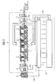
- FIG. 1 shows a plant for the production of metal strip 6, which comprises a roughing train 2, a finishing train 3 and a cooling line 4.
- the metal strip 6 is preferably rolled hot.
- a reel device 5 is preferably arranged. From her rolled in the streets 2 and 3 and cooled in the cooling section 4 metal strip 6 is reeled.
- the streets 2 and 3, a band source 1 is arranged upstream.
- the band source 1 is designed, for example, as a furnace in which metal slabs are heated.
- the band source 1 may for example also be formed as a continuous casting plant, is produced in the metal strip 6, which is then fed to the roughing train 2.
- the plant for steelmaking and in particular the roads 2, 3 and the cooling section 4 and the at least one reel device 5 are controlled by means of a control method which is carried out by a computing device 10.
- the computing device 10 is coupled with one or more of the components 1 to 5 of the plant for steel production control technology.
- the computing device 10 is programmed with a computer program designed as a control program, based on which it performs the inventive method for controlling or regulating the temperature of the metal strip 6.
- the metal strip or slab 6 leaves the strip source 1 and is first rolled in the roughing train 2 to an input thickness for the finished section 3. Within the finishing train, the belt 6 is then by means of the rolling stands 3 ' rolled to its final thickness. The subsequent cooling section 4 cools the belt to a predetermined reel temperature.
- a suitable temperature profile for the finishing train 3 and for the cooling section 4 must be complied with.
- a target temperature profile is preferably predetermined as a function of, for example, the type of installation, the operating mode, the respective application and desired properties of the metal strip 6.
- FIG. 5 shows a computing device 10 for controlling a cooling section 4.
- the computing device 10 has a prediction module 21 and a module 22 for preferably online calculations, in particular during the cooling process.
- the actuators of the finishing train 4 can be initialized.
- estimated values for missing measured values for example the input speed of the metal strip, the temperature of the metal strip at the end of the finishing train 3 and the strip thickness, are used.
- desired material values 105 serve as input-side input values for the prediction module 21.
- the prediction 20 within the prediction module 21 is iteratively executed. This means that calculations with different amounts of coolant are repeated until predetermined errors are minimized.
- the pre-calculation 20 is therefore coupled with online-enabled cooling-distance monitor 11 and an A-adaptation 18.
- the calculation module 22 has a cooling line monitor 11 and a cooling line control 12, which are coupled together.
- the cooling line monitor 11 and the cooling line control 12 control the actuators of the cooling section 4 and are preferably with one or more models of the cooling section, which may be stored, for example, in a model library 19. Preferably, one of the models is used to control the actuators.
- the cooling line control 12 sends control signals 101 to the cooling section 4, for example in the form of control patterns for coolant valves.
- FIG. 1 describes the operation of the cooling distance monitor 11 and the cooling line control 12 in more detail.
- the cooling distance monitor 11 determines the state of the cooling section 4.
- the input parameters for the cooling section monitor 11 are, for example, values such as the speed of the metal strip 6, strip temperatures and coolant temperatures and coolant pressure.
- a final rolling temperature measuring station 8 for measuring the temperature of the metal strip 6 is arranged in the entrance area of the cooling section 4.
- the temperature of the end of the finishing train 3 or the temperature between the finishing train 3 and the cooling section 4 is measured.
- a final temperature measuring station 9 is preferably arranged.
- the temperature is measured in front of the reel device 5 or at the end of the cooling section 4.
- Input variables of the cooling distance monitor 11 are the input temperatures 103 of the metal strip determined at the final rolling temperature measuring station 8, the starting temperatures 104 of the metal strip determined at the coiling temperature measuring station 9 as well as further band data 102 which are preferably located in the finishing train 3, e.g. at or shortly after the last rolling stand 3 ', are determined.
- valve positions 101 are transmitted to the cooling line monitor, which, however, usually checked by the cooling line monitor 11 for plausibility become.
- the cooling distance monitor 11 always determines the current state of the cooling section 4.
- the control or regulation according to the invention takes place clock cycle, preferably in control steps.
- the cooling line control 12 determines the valve positions 101 of the valves 7 of the cooling section 4 for the next control step. In this case, an optimization problem is preferably solved, which will be discussed in more detail in the text
- an iteration step is preferably carried out in each time cycle, wherein, starting from the solution of the optimization problem assigned to a current time cycle, at least one actuating signal is applied to the installation. Preferably, further updated measured values are taken into account in the solution of the optimization problem for a subsequent clock cycle. In this way, a closed loop can be formed.
- Figure 6 shows a possible temperature profile T over the locations x of the cooling section 4, wherein the cooling section 4 is limited by the beginning of the cooling section x A and the end of the cooling section x E.
- a comparable image would result from applying a temperature history T over time.
- FIG. 3 illustrates the model-predictive control of the cooling section in more detail.
- preferably not individual valves 7a or 7b, referred to collectively as 7, are actuated by the cooling-zone controller 12, but rather valve groups consisting of one or more valves 7.
- the control region 14 can be divided into a plurality of subregions 14a and 14b, wherein preferably each subregion 14a or 14b is assigned a valve group.
- control range 14 Within the limits of the control range 14, the boundaries of which usually coincide with the limits of the cooling path, a distinction can be made with regard to the control between a main control range 15 and a trim control range 16.
- individual band points (13a, 13b) are tracked.
- a model-predictive algorithm is used to control and regulate the cooling section.
- actuators for N u time steps are determined in the future as a solution of a preferably quadratic optimization problem, wherein predictions are made with the model for N y time steps.
- N u may be 1 or even a natural number greater than 1. In the latter case, only the calculated actuator settings for the first time step are usually implemented. For the next time step, we recalculated taking into account current measured values or predicted values.
- N y must be chosen large enough to overcome the largest dead time available.
- the largest dead time results from the largest distance of a temperature measuring point and the position of the nearest upstream free control valve.
- a suitable, preferably linearized, strip temperature model is used.
- the preferably square Optimization problem can easily be integrated with equation and inequality constraints. In this way, actuator limitations and different cooling line layouts can be taken into account particularly advantageously and preferably such that no excessive changes have to be made to the computing device 10 or to the prediction module 21 and / or the calculation module 22.
- a model predictive control of the cooling section can also be based on the enthalpy curve in the cooling section.
- the enthalpy profile over the location x or over time is comparable to the temperature profile over the location (see also FIG. 6) or over time.
- the computing device 10 it is possible for the computing device 10 to have a cooling line control module 12, which in turn has a plurality of partial control modules 17a, 17b, which correspond to different control regions 14a and 14b.
- the control or regulation of the cooling section 4 according to the invention is independent of the cooling route layout and, because of the model-predictive control, also offers optimum control of the control limits at the control limits. Specifications can be weighted differently in terms of prioritization in a flexible way. Edge-masking can be integrated into the control method according to the invention.
- the method according to the invention can be designed in such a way that the speed of the metal strip 6 can also be controlled, which makes its use possible, for example, also for heavy plate mills.
- a finishing train 3 can also be regulated according to the invention.
- interstand cooling devices are further possible actuators in a finishing line.
- a typical number of actuators for one Cooling section for example, about 200 valves 7. This is a significantly higher number of actuators than for a typical finishing line.
- An overall control for a plurality of plant parts 1 to 5 can preferably be achieved as described below, for example for a finishing train 3 and a cooling section 4.
- the temperature model of the finishing train 3 and the temperature model of the cooling section 4 are concatenated.
- a preferably quadratic optimization problem with preferably linear secondary conditions is determined, by means of which a common control method is provided for both equipment parts 3 and 4.
- the optimization of the problem thus provides the settings for the interstitial cooling of the finishing train 3, the cooling line valves 7 of the cooling section 4 and speed of the metal strip 6, in particular for each next control step.
Landscapes
- Engineering & Computer Science (AREA)
- Mechanical Engineering (AREA)
- Control Of Metal Rolling (AREA)
- Control Of Heat Treatment Processes (AREA)
- Heat Treatment Of Strip Materials And Filament Materials (AREA)
Abstract
Description
Die Erfindung betrifft ein Verfahren zur Steuerung und/oder Regelung der Temperatur eines Metallbandes in einer Anlage der Stahlindustrie, insbesondere in einer Kühlstrecke, gemäß dem Oberbegriff des Anspruchs 1. Ein solches Verfahren ist aus VS6185970 B bekannt.The invention relates to a method for controlling and / or regulating the temperature of a metal strip in a plant of the steel industry, in particular in a cooling section, according to the preamble of
Aus der DE 199 63 186 A1 ist ein Steuerverfahren für eine Kühlstrecke bekannt, der eine Fertigstraße zum Walzen von Metall-Warmband vorgeordnet ist. Bei diesem Steuerverfahren werden beim Einlaufen des Warmbandes in die Kühlstrecke Bandpunkte und deren Anfangstemperaturen erfasst und den erfassten Bandpunkten individuell Solltemperaturverläufe zugeordnet. Die Bandpunkte, deren Anfangstemperaturen und deren Solltemperaturverläufe werden einem Modell für die Kühlstrecke zugeführt. Die Bandpunkte werden beim Durchlaufen der Kühlstrecke wegverfolgt. In der Kühlstrecke wird das Warmband mittels Temperaturbeeinflussungseinrichtungen Temperaturbeeinflussungen unterworfen. Die Wegverfolgungen und die Temperaturbeeinflussungen werden ebenfalls dem Modell zugeführt. Das Modell ermittelt in Echtzeit erwartete Ist- Temperaturen der erfassten Bandpunkte und ordnet diese den Bandpunkten zu. Dadurch steht für jeden Bandpunkt zu jedem Zeitpunkt die Temperatur als Funktion über die Banddicke zur Verfügung. Ferner ermittelt es anhand der den erfassten Bandpunkten zugeordneten Solltemperaturverläufe und der erwarteten Ist-Temperaturen Ansteuerwerte für die Temperaturbeeinflussungseinrichtungen und führt die Ansteuerwerte diesen zu. Die Temperaturführung dient insbesondere zum gezielten Einstellen von Material- und Gefügeeigenschaften des Metall-Warmbandes. In der Regel wird dabei die Temperaturführung derart durchgeführt, dass ein vorbestimmter Haspeltemperaturverlauf vom Ausgang der Kühlstrecke möglichst gut erreicht wird.From DE 199 63 186 A1 a control method for a cooling section is known, which is preceded by a finishing train for rolling of hot metal strip. In this control method, when the hot strip enters the cooling section, band points and their initial temperatures are detected and individual setpoint temperature profiles are assigned to the detected band points. The band points, their initial temperatures and their desired temperature curves are fed to a model for the cooling section. The band points are tracked as they pass through the cooling section. In the cooling section, the hot strip is subjected to temperature influencing by means of temperature influencing devices. The tracking and the temperature changes are also fed to the model. The model determines in real time expected actual temperatures of the recorded band points and assigns them to the band points. As a result, the temperature as a function of the strip thickness is available for each band point at any time. Furthermore, it determines control values for the temperature-influencing devices on the basis of the setpoint temperature profiles assigned to the detected band points and the expected actual temperatures, and supplies the control values to them. The temperature control is used in particular for targeted adjustment of material and structural properties of the metal hot strip. As a rule, the temperature control is carried out in such a way that a predetermined reel temperature curve is achieved as well as possible from the outlet of the cooling section.
Maßgeblich für Material- und Gefügeeigenschaften des Metallbands sind neben der chemischen Zusammensetzung und Parametern des Umformprozesses, wie z.B. die Abnahmeverteilung über die Gerüste der Fertigstaffel und der zeitliche Temperaturverlauf des Bandmaterials beim Durchlauf durch die Anlage.Decisive for material and structural properties of the metal strip are, in addition to the chemical composition and parameters of the forming process, such as. the acceptance distribution over the stands of the finishing scale and the temporal temperature profile of the strip material as it passes through the plant.
Die letzten Stellglieder für den Temperaturverlauf des Metallbandes innerhalb der Anlage befinden sich dabei in der Regel innerhalb der Kühlstrecke. In der Kühlstrecke vollzieht sich häufig auch die Phasenumwandlung des Materials. Als Stellglieder dienen in der Regel die Ventile der Kühlstrecke. Bei bestimmten Kühlstrecken, wie z.B. Grobblechstraßen, kann zusätzlich auch der Massenfluss, d.h. insbesondere die Bandgeschwindigkeit, gestellt werden.The last actuators for the temperature profile of the metal strip within the system are usually located within the cooling section. In the cooling section, the phase transformation of the material often takes place. As actuators usually serve the valves of the cooling section. For certain cooling sections, such as Heavy plate mills, in addition, the mass flow, i. in particular, the belt speed, are provided.
Aufgabe der vorliegenden Erfindung ist es, die Steuerung bzw. die Regelung der Temperatur eines Metallbandes, dabei insbesondere in einer Kühlstrecke, in einer Anlage der Stahlindustrie derart zu verbessern, dass die Nachteile bekannter Steuerungen bzw. Regelungen weitestgehend vermieden werden und die Effizienz der Steuerung bzw. Regelung erhöht wird.The object of the present invention is to improve the control or the regulation of the temperature of a metal strip, in particular in a cooling section, in a plant of the steel industry in such a way that the disadvantages of known controls or regulations are largely avoided and the efficiency of the control or Control is increased.
Die Aufgabe wird durch ein Verfahren zur Steuerung und/oder Regelung der Temperatur eines Metallbandes in einer Anlage der Stahlindustrie gelöst, insbesondere in einer Kühlstrecke, die einer Walzstraße zum Walzen von Metallwarmband nachgeordnet ist, wobei zur Ermittlung von Stellsignalen ein Soll-Temperaturverlauf mit einem Ist-Temperaturverlauf verglichen wird, und wobei Bandpunkte wegverfolgt werden, wobei ein Temperaturverlauf für einzelne Bandpunkte ermittelt wird und wobei unter Berücksichtigung von Nebenbedingungen mindestens eine Zielfunktion für mehrere Stellglieder in einem Regelbereich der Anlage, insbesondere in der Kühlstrecke, gebildet wird.The object is achieved by a method for controlling and / or regulating the temperature of a metal strip in a plant of the steel industry, in particular in a cooling section, which is arranged downstream of a rolling train for rolling metal heat, wherein for determining actuating signals a desired temperature profile with an actual Temperature characteristic is compared, and wherein band points are tracked, wherein a temperature profile for individual band points is determined and wherein, taking into account side conditions at least one target function for a plurality of actuators in a control range of the system, in particular in the cooling line is formed.
Durch die Berücksichtigung von Nebenbedingungen, die vorzugsweise Anlagengrenzen bzw. Stellbegrenzungen entsprechen, wird es möglich, insbesondere für verschiedene Kühlstrecken-Layouts und vor allem für den Fall eines vorgegebenen Temperatur- bzw. Abkühlverlaufs, (Stell-) Vorgaben zu ermitteln, die Stellbegrenzungen in sinnvoller Weise berücksichtigen. So wird beispielsweise bei einer zweigeteilten Kühlstrecke vermieden, dass die Vorgabe einer zu hohen Temperatur zwischen beiden Teilkühlstrecken zur Folge hat, dass die Haspeltemperatur mit der verfügbaren Kühlmittelmenge der zweiten Teilkühlstrecke nicht mehr erreicht werden kann. Derart und insbesondere auch durch die Wegverfolgung der Bandpunkte wird die Genauigkeit der Steuerung bzw. Regelung deutlich verbessert.By taking into account secondary conditions, which preferably correspond to plant limits or control limits, it becomes possible, in particular for different cooling line layouts and, above all, in the case of a predetermined temperature or cooling curve, to determine (control) specifications, the control limits are more meaningful Consider the way. Thus, it is avoided, for example, in a two-part cooling section, that the specification of an excessively high temperature between the two partial cooling sections has the result that the reel temperature can no longer be achieved with the available coolant quantity of the second partial cooling section. In this way, and in particular also by the tracking of the band points, the accuracy of the control or regulation is significantly improved.
Mit Vorteil wird die Zielfunktion durch Lösen eines Optimierungsproblems minimiert bzw. maximiert. Derart wird eine Steuerung bzw. Regelung auch dann möglich, wenn ein Temperatur- bzw. Abkühlverlauf vorgegeben wird, der nicht exakt realisierbar ist. Das Verfahren ermittelt dann die bestmögliche Approximation.Advantageously, the objective function is minimized or maximized by solving an optimization problem. Such a control or regulation is also possible if a temperature or cooling is specified, which is not exactly feasible. The method then determines the best possible approximation.
Mit Vorteil wird ein quadratisches Optimierungsproblem gelöst. Derart wird die Zeit zum Lösen des Optimierungsproblems in der Regel deutlich verringert.Advantageously, a quadratic optimization problem is solved. Thus, the time to solve the optimization problem is usually significantly reduced.
Mit Vorteil wird der Ist-Temperaturverlauf und/oder der Soll-Temperaturverlauf des Metallbandes unter Zuhilfenahme mindestens eines Modells ermittelt. Derart wird eine verbesserte Steuerung bzw. Regelung der Temperatur des Metallbandes auch dann ermöglicht, wenn die tatsächliche Bandtemperatur an für die Steuerung bzw. Regelung relevanten Orten, insbesondere der Kühlstrecke, nicht gemessen werden kann.Advantageously, the actual temperature profile and / or the desired temperature profile of the metal strip is determined with the aid of at least one model. In this way, improved control or regulation of the temperature of the metal strip is also made possible if the actual strip temperature at locations relevant for the control or regulation, in particular the cooling section, can not be measured.
Alternativ oder zusätzlich wird der Ist-Enthalpieverlauf und/oder der Soll-Enthalpieverlauf ermittelt.Alternatively or additionally, the actual enthalpy profile and / or the desired enthalpy profile are determined.
Mit Vorteil wird die Zielfunktion durch Lösen eines Optimierungsproblems mittels Vorausberechnung minimiert bzw. maximiert. Insbesondere wird auf diese Weise die zur Voreinstellung der Stellglieder benötigte Zeit deutlich reduziert. Vorzugsweise werden derart zudem die Stellglieder optimal im Hinblick auf eine nachfolgende Online-Regelung voreingestellt,Advantageously, the objective function is minimized or maximized by solving an optimization problem by means of precalculation. In particular, the time required for presetting the actuators is significantly reduced in this way. Preferably, in addition, the actuators are optimally preset with regard to a subsequent online control,
Mit Vorteil wird die Zielfunktion vorzugsweise online durch Lösen eines Optimierungsproblems iterativ minimiert bzw. maximiert.Advantageously, the objective function is preferably minimized or maximized online by solving an optimization problem.
Vorteilhafte Weiterbildungen des Verfahrens sind in den Ansprüchen 8 bis 14 angegeben.Advantageous developments of the method are specified in claims 8 to 14.
Weitere Lösungen der erfindungsgemäßen Aufgabe sind in den Ansprüchen 15 bis 18 angegeben.Further solutions of the object according to the invention are specified in
Weitere Vorteile und Einzelheiten ergeben sich aus der nachfolgenden Beschreibung mehrerer Ausführungsbeispiele der Erfindung in Verbindung mit den Zeichnungen. Dabei zeigen beispielhaft:
- FIG 1
- den prinzipiellen Aufbau eines Walzwerks,
- FIG 2
- die Kühlstrecke eines Walzwerks sowie eine zu deren Steuerung bzw. Regelung dienende Recheneinrichtung,
- FIG 3
- eine Kühlstrecke und eine ihr schematisch zugeordnete Kühlstreckenregelung,
- FIG 4
- mögliche Module einer Kühlstreckenregelung,
- FIG 5
- Vorausberechnung und eine Echtzeitregelung einer Kühlstrecke,
- FIG 6
- einen möglichen Temperaturverlauf eines Metallbandes in der Kühlstrecke.
- FIG. 1
- the basic structure of a rolling mill,
- FIG. 2
- the cooling section of a rolling mill as well as a computing device serving for its control or regulation,
- FIG. 3
- a cooling section and a cooling line control, which is assigned to it schematically,
- FIG. 4
- possible modules of a cooling line control,
- FIG. 5
- Precalculation and real-time control of a cooling line,
- FIG. 6
- a possible temperature profile of a metal strip in the cooling section.
Figur 1 zeigt eine Anlage zur Erzeugung von Metallband 6, die eine Vorstraße 2, eine Fertigstraße 3 und eine Kühlstrecke 4 umfasst. Das Metallband 6 wird dabei vorzugsweise warm gewalzt. Hinter der Kühlstrecke 4 ist vorzugsweise eine Haspelvorrichtung 5 angeordnet. Von ihr wird das in den Straßen 2 und 3 gewalzte und in der Kühlstrecke 4 gekühlte Metallband 6 aufgehaspelt. Den Straßen 2 bzw. 3 ist eine Bandquelle 1 vorgeordnet. Die Bandquelle 1 ist beispielsweise als Ofen ausgebildet, in dem Metallbrammen erwärmt werden. Die Bandquelle 1 kann beispielsweise auch als Stranggießanlage ausgebildet sein, in der Metallband 6 erzeugt wird, das dann der Vorstraße 2 zugeführt wird.FIG. 1 shows a plant for the production of metal strip 6, which comprises a roughing train 2, a finishing
Die Anlage zur Stahlerzeugung und insbesondere die Straßen 2, 3 sowie die Kühlstrecke 4 und die mindestens eine Haspelvorrichtung 5 werden mittels eines Steuerverfahrens gesteuert, das von einer Recheneinrichtung 10 ausgeführt wird. Hierzu ist die Recheneinrichtung 10 mit ein oder mehreren der Komponenten 1 bis 5 der Anlage zur Stahlerzeugung steuerungstechnisch gekoppelt. Die Recheneinrichtung 10 ist mit einem als Computerprogramm ausgebildeten Steuerprogramm programmiert, aufgrund dessen sie das erfindungsgemäße Verfahren zur Steuerung bzw. zur Regelung der Temperatur des Metallbandes 6 ausführt.The plant for steelmaking and in particular the
Gemäß Figur 1 verlässt das Metallband bzw. die Bramme 6 die Bandquelle 1 und wird zunächst in der Vorstraße 2 auf eine Eingangsdicke für die Fertigstrecke 3 gewalzt. Innerhalb der Fertigstraße wird das Band 6 dann mittels der Walzgerüste 3' auf seine Enddicke gewalzt. Die anschließende Kühlstrecke 4 kühlt das Band auf eine vorgegebene Haspeltemperatur ab.According to FIG. 1, the metal strip or slab 6 leaves the
Um gewünschte mechanische Eigenschaften des Bandes 6 zu gewährleisten, muss ein geeigneter Temperaturverlauf für die Fertigstraße 3 und für die Kühlstrecke 4 eingehalten werden. Hierzu wird vorzugsweise ein Soll-Temperaturverlauf abhängig von beispielsweise dem Anlagentyp, dem Betriebsmodus, dem jeweiligen Auftrag und gewünschten Eigenschaften des Metallbandes 6 vorgegeben.In order to ensure desired mechanical properties of the belt 6, a suitable temperature profile for the finishing
Figur 5 zeigt eine Recheneinrichtung 10 zur Steuerung einer Kühlstrecke 4. Dabei weist die Recheneinrichtung 10 ein Vorausberechnungsmodul 21 und ein Modul 22 für vorzugsweise online Berechnungen insbesondere während des Kühlprozesses auf.FIG. 5 shows a
Mit Hilfe des Vorausberechnungsmoduls 21 können die Stellglieder der Fertigstraße 4 initialisiert werden. Dazu werden beispielsweise Schätzwerte für fehlende Messwerte, beispielsweise die Eingangsgeschwindigkeit des Metallbandes, die Temperatur des Metallbandes am Ende der Fertigstraße 3 und die Banddicke, verwendet. Als bedienerseitige Eingabewerte für das Vorausberechnungsmodul 21 dienen beispielsweise gewünschte Materialwerte 105.By means of the
Die Vorausberechnung 20 innerhalb des Vorausberechnungsmoduls 21 läuft iterativ ab. Das bedeutet, dass Berechnungen mit verschiedenen Kühlmittelmengen wiederholt werden, bis vorgegebene Fehler minimiert sind. Die Vorausberechnung 20 ist daher mit online fähigen Kühlstreckenmonitor 11 sowie einer A-daptation 18 gekoppelt.The
Das Berechnungsmodul 22 weist einen Kühlstreckenmonitor 11 und eine Kühlstreckenregelung 12 auf, die miteinander gekoppelt sind. Der Kühlstreckenmonitor 11 und die Kühlstreckenregelung 12 steuern die Stellglieder der Kühlstrecke 4 und sind vorzugsweise mit einem oder mehreren Modellen der Kühlstrecke, die z.B. in einer Modellbibliothek 19 abgelegt sein können, gekoppelt. Vorzugsweise wird eines der Modelle zur Steuerung der Stellglieder verwendet. Die Kühlstreckenregelung 12 gibt Stellsignale 101 an die Kühlstrecke 4 weiter, beispielsweise in Form von Stellmustern für Kühlmittelventile.The
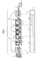
Figur 2 beschreibt die Funktionsweise des Kühlstreckenmonitors 11 und der Kühlstreckenregelung 12 genauer.Figure 2 describes the operation of the
Der Kühlstreckenmonitor 11 ermittelt den Zustand der Kühlstrecke 4. Als Eingangsparameter für den Kühlstreckenmonitor 11 dienen beispielsweise Werte wie die Geschwindigkeit des Metallbandes 6, Bandtemperaturen sowie Kühlmitteltemperaturen und Kühlmitteldruck.The cooling distance monitor 11 determines the state of the
Weitere Eingangsgrößen sind die Einstellungen der Stellglieder, d.h. also vorzugsweise der Ventile 7.Other inputs are the settings of the actuators, i. So preferably the valves. 7
Vorzugsweise ist im Eingangsbereich der Kühlstrecke 4 ein Endwalztemperatur-Messplatz 8 zur Messung der Temperatur des Metallbands 6 angeordnet. Hier wird die Temperatur des am Ende der Fertigstraße 3 bzw. die Temperatur zwischen Fertigstraße 3 und Kühlstrecke 4 gemessen. Am Ende der Kühlstrecke 4 ist vorzugsweise ein Endtemperatur-Messplatz 9 angeordnet. Hier wird die Temperatur vor der Haspelvorrichtung 5 bzw. am Ende der Kühlstrecke 4 gemessen. Eingangsgrößen des Kühlstreckenmonitors 11 sind die am Endwalztemperatur-Messplatz 8 ermittelten Eingangstemperaturen 103 des Metallbandes, die am Haspeltemperatur-Messplatz 9 ermittelten Ausgangstemperaturen 104 des Metallbandes sowie weitere Banddaten 102, die vorzugsweise in der Fertigstraße 3, z.B. an oder kurz nach deren letztem Walzgeüst 3', ermittelt werden.Preferably, a final rolling temperature measuring station 8 for measuring the temperature of the metal strip 6 is arranged in the entrance area of the
Von der Kühlstreckenregelung 12 werden an den Kühlstreckenmonitor 11 Ventilstellungen 101 übermittelt, die in der Regel jedoch vom Kühlstreckenmonitor 11 nicht auf Plausibilität geprüft werden. Der Kühlstreckenmonitor 11 ermittelt stets den gegenwärtigen Zustand der Kühlstrecke 4.From the
Die erfindungsgemäße Steuerung bzw. Regelung erfolgt Zeittakt weise vorzugsweise in Regelschritten. Die Kühlstreckenregelung 12 ermittelt die Ventilstellungen 101 der Ventile 7 der Kühlstrecke 4 für den jeweils nächsten Regelschritt. Dabei wird vorzugsweise ein Optimierungsproblem gelöst, auf das im weiteren Text noch näher eingegangen wirdThe control or regulation according to the invention takes place clock cycle, preferably in control steps. The
Erfindungsgemäß wird vorzugsweise in jedem Zeittakt ein Iterationsschritt durchgeführt wird, wobei ausgehend von der einem aktuellen Zeittakt zugeordneten Lösung des Optimierungsproblems mindestens ein Stellsignal auf die Anlage aufgeschaltet wird. Vorzugsweise werden für einen nachfolgenden Zeittakt weitere aktualisierte Messwerte bei der Lösung des Optimierungsproblems berücksichtigt. Derart kann ein geschlossener Regelkreis gebildet werden.According to the invention, an iteration step is preferably carried out in each time cycle, wherein, starting from the solution of the optimization problem assigned to a current time cycle, at least one actuating signal is applied to the installation. Preferably, further updated measured values are taken into account in the solution of the optimization problem for a subsequent clock cycle. In this way, a closed loop can be formed.
Es ist vorteilhaft wenn bei einer hohen Anzahl von Stellgliedern, wie sie für die Kühlstrecke 4 typisch ist, bei der Aufstellung des vorzugsweise quadratischen Optimierungsproblems nicht einzelne Ventile sondern Gruppen von Ventilen als Stellglied aufgefasst werden. Die Aufteilung des berechneten Stellwerts auf die einzelnen Ventile erfolgt über eine geeignete Schaltheuristik. Das Zusammenfassen von Ventilen zu Ventilgruppen ist besonders für eine online, d.h. in Echtzeit, erfolgende Lösung des Optimierungsproblems besonders vorteilhaft.It is advantageous if at a high number of actuators, as is typical for the
Figur 6 zeigt einen möglichen Temperaturverlauf T über den Orten x der Kühlstrecke 4, wobei die Kühlstrecke 4 durch den Anfang der Kühlstrecke xA und das Ende der Kühlstrecke xE begrenzt ist. Ein vergleichbares Bild würde sich beim Auftragen eines Temperaturverlaufs T über die Zeit ergeben.Figure 6 shows a possible temperature profile T over the locations x of the
Figur 3 stellt die modellprädiktive Regelung der Kühlstrecke näher dar. Dabei werden von der Kühlstreckenregelung 12 vorzugsweise nicht einzelne Ventile 7a bzw. 7b, zusammenfassend als 7 bezeichnet, angesteuert, sondern aus ein oder mehreren Ventilen 7 bestehende Ventilgruppen. Dabei kann dementsprechend beispielsweise der Regelbereich 14 in mehrere Teilbereiche 14a und 14b aufgeteilt werden, wobei vorzugsweise jedem Teilbereich 14a bzw. 14b eine Ventilgruppe zugeordnet ist.FIG. 3 illustrates the model-predictive control of the cooling section in more detail. In this case, preferably not
Innerhalb der Grenzen des Regelbereichs 14, dessen Grenzen sich mit den Grenzen der Kühlstrecke in der Regel decken, kann hinsichtlich der Regelung zwischen einem Hauptregelbereich 15 und einem Abgleichsregelbereich 16 unterschieden werden. Vorzugsweise werden einzelne Bandpunkte (13a, 13b) wegverfolgt.Within the limits of the
Zur Steuerung und Regelung der Kühlstrecke wird ein modellprädiktiver Algorithmus eingesetzt. Dabei werden Stellglieder für Nu Zeitschritte in die Zukunft als Lösung eines vorzugsweise quadratischen Optimierungsproblems bestimmt, wobei mit dem Modell für Ny Zeitschritte Vorhersagen getroffen werden.A model-predictive algorithm is used to control and regulate the cooling section. In this case, actuators for N u time steps are determined in the future as a solution of a preferably quadratic optimization problem, wherein predictions are made with the model for N y time steps.
Nu darf 1 oder auch eine natürliche Zahl größer 1 sein. In letzterem Fall werden in der Regel nur die berechneten Stellgliedeinstellungen für den ersten Zeitschritt implementiert. Für den nächsten Zeitschritt wir unter Berücksichtigung aktueller Messwerte bzw. Vorhersagewerte neu gerechnet.N u may be 1 or even a natural number greater than 1. In the latter case, only the calculated actuator settings for the first time step are usually implemented. For the next time step, we recalculated taking into account current measured values or predicted values.
Ny muss so groß gewählt werden, dass die größte vorliegende Totzeit überwunden wird. Die größte Totzeit ergibt sich aus dem größten Abstand einer Temperaturmessstelle und der Position des nächstliegenden vorgeschalteten freien Stellventils. Zur Aufstellung des vorzugsweise quadratischen Optimierungsproblems wird ein geeignetes vorzugsweise linearisiertes Bandtemperaturmodell verwendet. In das vorzugsweise quadratische Optimierungsproblem lassen sich leicht Gleichungs- und Ungleichungsnebenbedingungen integrieren. Derart können Stellgliedbegrenzungen und unterschiedliche Kühlstreckenlayouts besonders vorteilhaft und vorzugsweise derart berücksichtigt werden, dass an der Recheneinrichtung 10 bzw. am Vorausberechnungsmodul 21 und/oder dem Berechnungsmodul 22 keine übermäßigen Änderungen vorgenommen werden müssen.N y must be chosen large enough to overcome the largest dead time available. The largest dead time results from the largest distance of a temperature measuring point and the position of the nearest upstream free control valve. To set up the preferably quadratic optimization problem, a suitable, preferably linearized, strip temperature model is used. In the preferably square Optimization problem can easily be integrated with equation and inequality constraints. In this way, actuator limitations and different cooling line layouts can be taken into account particularly advantageously and preferably such that no excessive changes have to be made to the
Alternativ oder zusätzlich kann eine Modellprädiktive Regelung der Kühlstrecke auch auf dem Enthalpieverlauf in der Kühlstrecke fußen. Der Enthalpieverlauf über dem Ort x bzw. über der Zeit ist dabei vergleichbar mit dem Temperaturverlauf über dem Ort (siehe auch Figur 6) bzw. über der Zeit.Alternatively or additionally, a model predictive control of the cooling section can also be based on the enthalpy curve in the cooling section. The enthalpy profile over the location x or over time is comparable to the temperature profile over the location (see also FIG. 6) or over time.
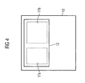
Wie Figur 4 veranschaulicht, ist es möglich, dass die Recheneinrichtung 10 ein Modul zur Kühlstreckenregelung 12 aufweist, das seinerseits mehrere Teilregelmodule 17a, 17b aufweist, die unterschiedlichen Regelbereichen 14a und 14b entsprechen.As FIG. 4 illustrates, it is possible for the
Die erfindungsgemäße Steuerung bzw. Regelung der Kühlstrecke 4 ist unabhängig vom Kühlstreckenlayout und bietet aufgrund der modellprädiktiven Regelung ein optimales Verhalten der Steuerung auch an den Stellbegrenzungen. Vorgaben können auf flexible Weise im Sinne einer Priorisierung unterschiedlich gewichtet werden. In das erfindungsgemäße Steuerungs- bzw. Regelungsverfahren ist Edge-Masking integrierbar.The control or regulation of the
Das erfindungsgemäße Verfahren lässt sich derart ausgestalten, dass auch die Geschwindigkeit des Metallbandes 6 gesteuert werden kann, was seine Verwendung beispielsweise auch für Grobblechstraßen möglich macht.The method according to the invention can be designed in such a way that the speed of the metal strip 6 can also be controlled, which makes its use possible, for example, also for heavy plate mills.
Insbesondere lässt sich auch eine Fertigstrasse 3 erfindungsgemäß regeln. Neben Bandgeschwindigkeit sind bei einer Fertigstrasse 3 Zwischengerüstkühlvorrichtungen weitere mögliche Stellglieder. Eine typische Zahl von Stellgliedern für eine Kühlstrecke sind beispielsweise ca. 200 Ventile 7. Dies ist eine deutlich höhere Zahl von Stellgliedern als für eine typische Fertigstrasse 3.In particular, a finishing
Eine übergreifende Steuerung bzw. Regelung für mehrere Anlagenteile 1 bis 5 kann vorzugsweise wie nachstehend beispielsweise für eine Fertigstrasse 3 und eine Kühlstrecke 4 beschrieben erzielt werden.An overall control for a plurality of
Zur übergreifenden Steuerung bzw. Regelung werden vorzugsweise das Temperaturmodell der Fertigstraße 3 und das Temperaturmodell der Kühlstrecke 4 verkettet. Durch Addition der Zielfunktionen für beide Anlagenteile 3 und 4 wird ein vorzugsweise quadratisches Optimierungsproblem mit vorzugsweise linearen Nebenbedingungen ermittelt, mit Hilfe dessen ein gemeinsames Steuerverfahren für beide Anlagenteile 3 und 4 bereitgestellt wird. Die Optimierung des Problems liefert so die Einstellungen für die Zwischengerüstkühlungen der Fertigstrasse 3, die Kühlstreckenventile 7 der Kühlstrecke 4 und Geschwindigkeit des Metallbandes 6, insbesondere für den jeweils nächsten Regelschritt.For overall control or regulation, preferably the temperature model of the finishing
Claims (18)
- Method for controlling and/or regulating the temperature of strip metal (5) in a system employed in the steel industry, especially in a cooling path (4) located downstream of a rolling train (2,3) for rolling a hot strip metal (6), wherein a desired temperature gradient is compared for the purpose of determining adjusting signals with an actual temperature gradient, characterised in that points (13a, 13b) on the strip are route-tracked, in that a temperature gradient is determined for individual points (13a, 13b) on the strip, and in that at least one target function is formed for a plurality of actuators in a regulating section of the system, especially in the cooling path (4), taking secondary conditions into account.
- Method according to claim 1,
characterised in that the target function is minimised by solving an optimisation problem. - Method according to claim 1 or 2,
characterised in that the target function is maximised by solving an optimisation problem. - Method according to claim 2 or 3,
characterised in that a quadratic optimisation problem is solved. - Method according to one of the preceding claims,
characterised in that the actual temperature gradient and/or desired temperature gradient of the strip metal (6) is determined with the aid of at least one model. - Method according to one of the preceding claims,
characterised in that the actual enthalpy gradient and/or desired enthalpy gradient is determined with the aid of at least one model. - Method according to claim 5 or 6,
characterised in that the model is adapted online. - Method according to one of claims 2 to 7,
characterised in that the target function is minimised or maximised by solving an optimisation problem using predictive calculating. - Method according to one of the preceding claims,
characterised in that the target function is iteratively minimised or maximised preferably online by solving an optimisation problem. - Method according to claim 9,
characterised in that an iteration step is carried out during each clocked pulse with at least one adjusting signal being applied to the system proceeding from the optimisation problem's solution assigned to a current clocked pulse. - Method according to claim 10,
characterised in that further measurands are taken into account for a succeeding clocked pulse when the optimisation problem is being solved. - Method according to claim 11,
characterised in that a closed control loop is formed. - Method according to one of the preceding claims,
characterised in that the optimisation problem is solved with linear secondary conditions. - Method according to one of the preceding claims,
characterised in that the temperature of the strip metal (5) is controlled and/or regulated in a plurality of parts (1 to 5) of the system employed in the steel industry, especially in the finishing train (3) and a cooling path (4) located downstream thereof. - Computer-program product comprising program-code means suitable for executing the steps of a method according to one of the preceding claims when the computer-program product is embodied on a calculating device.
- Calculating device (10) for executing the method according to one of claims 1 to 14, wherein the calculating device (10) directly and/or indirectly influences the temperature of the strip metal (6), characterised in that the calculating device has been programmed by means of a computer-program product according to claim 15.
- Calculating device (10) according to claim 16,
characterised in that it has a cooling-path monitor (11), a module for predictive calculating (20), a module for adapting (18), and a module for cooling-path regulating (12). - Calculating device (10) according to claim 16 or 17,
characterised in that it has a plurality of regulating modules (17a, 17b) for regulating actuators (7) and/or regulating regulating sections (14a, 14b) comprising one or more actuators.
Applications Claiming Priority (5)
| Application Number | Priority Date | Filing Date | Title |
|---|---|---|---|
| DE10308222 | 2003-02-25 | ||
| DE10308222 | 2003-02-25 | ||
| DE2003121792 DE10321792A1 (en) | 2003-05-14 | 2003-05-14 | Process for controlling and/or regulating the temperature of a metal strip in a metallurgical installation comprises comparing a temperature gradient to an actual temperature gradient to determine adjusting signals for a cooling path |
| DE10321792 | 2003-05-14 | ||
| PCT/EP2004/001365 WO2004076085A2 (en) | 2003-02-25 | 2004-02-13 | Method for regulating the temperature of a metal strip, especially in a cooling path |
Publications (3)
| Publication Number | Publication Date |
|---|---|
| EP1596999A2 EP1596999A2 (en) | 2005-11-23 |
| EP1596999B1 true EP1596999B1 (en) | 2006-12-20 |
| EP1596999B2 EP1596999B2 (en) | 2011-05-25 |
Family
ID=32928839
Family Applications (1)
| Application Number | Title | Priority Date | Filing Date |
|---|---|---|---|
| EP04710798A Expired - Lifetime EP1596999B2 (en) | 2003-02-25 | 2004-02-13 | Method for regulating the temperature of a metal strip, especially in a cooling path |
Country Status (7)
| Country | Link |
|---|---|
| US (1) | US7251971B2 (en) |
| EP (1) | EP1596999B2 (en) |
| JP (1) | JP2006518669A (en) |
| AT (1) | ATE348671T1 (en) |
| DE (1) | DE502004002370D1 (en) |
| NO (1) | NO20054189L (en) |
| WO (1) | WO2004076085A2 (en) |
Cited By (3)
| Publication number | Priority date | Publication date | Assignee | Title |
|---|---|---|---|---|
| EP2301685A1 (en) | 2009-09-23 | 2011-03-30 | Siemens Aktiengesellschaft | Control method for a treatment assembly for an elongated milling product |
| CN105689407A (en) * | 2016-01-20 | 2016-06-22 | 北京首钢股份有限公司 | Method for improving temperature control accuracy of thick-specification band steel subjected to ultra fast cooling |
| EP3099430B1 (en) | 2014-01-28 | 2017-11-01 | Primetals Technologies Germany GmbH | Cooling section with dual cooling to a particular target value |
Families Citing this family (14)
| Publication number | Priority date | Publication date | Assignee | Title |
|---|---|---|---|---|
| JP4752764B2 (en) * | 2004-10-14 | 2011-08-17 | 東芝三菱電機産業システム株式会社 | Material control method and apparatus for rolling, forging or straightening line |
| DE102007007560A1 (en) | 2007-02-15 | 2008-08-21 | Siemens Ag | Method for supporting at least partially manual control of a metalworking line |
| DE102008011303B4 (en) * | 2008-02-27 | 2013-06-06 | Siemens Aktiengesellschaft | Operating method for a cooling line for cooling a rolling stock with temperature-separated cooling to a final enthalpy value |
| US8935945B2 (en) * | 2008-11-19 | 2015-01-20 | Toshiba Mitsubishi-Electic Industrial Systems Corporation | Control system |
| CN102069095B (en) * | 2009-11-20 | 2014-05-21 | 浙江汇高机电科技有限公司 | Statistical learning-based method for predicting and controlling finish rolling temperature in fine rolling |
| EP2540404A1 (en) * | 2011-06-27 | 2013-01-02 | Siemens Aktiengesellschaft | Operating method for a hot strip mill |
| DE102013225579A1 (en) | 2013-05-22 | 2014-11-27 | Sms Siemag Ag | Device and method for controlling and / or regulating an annealing or heat treatment furnace of a metal material processing line |
| CN104043660B (en) * | 2013-09-26 | 2015-09-30 | 北大方正集团有限公司 | A kind of production technology of non-hardened and tempered steel |
| EP3495056B1 (en) * | 2017-12-11 | 2020-09-16 | Primetals Technologies Austria GmbH | Improved control of water conservancy of a cooling section |
| JP7058182B2 (en) * | 2018-06-08 | 2022-04-21 | 株式会社日立製作所 | Target temperature history creation device, target temperature history creation method and program |
| DE102018220382A1 (en) * | 2018-11-28 | 2020-05-28 | Sms Group Gmbh | Process for the production of a metallic band |
| DE102019104419A1 (en) * | 2019-02-21 | 2020-08-27 | Sms Group Gmbh | Method for setting different cooling processes for rolling stock over the bandwidth of a cooling section in a hot strip or heavy plate mill |
| EP3825789A1 (en) | 2019-11-20 | 2021-05-26 | Primetals Technologies Germany GmbH | Remote control of a plant for producing and / or treating a metal rolled product |
| CN113601806A (en) * | 2021-06-29 | 2021-11-05 | 无锡有孚精工科技有限公司 | Gas liquid cooling device, system and method for mold production |
Family Cites Families (11)
| Publication number | Priority date | Publication date | Assignee | Title |
|---|---|---|---|---|
| JPS58221606A (en) * | 1982-06-18 | 1983-12-23 | Sumitomo Metal Ind Ltd | Method for controlling cooling of band steel |
| JPH02169119A (en) * | 1988-12-22 | 1990-06-29 | Toshiba Corp | Method for controlling plate flatness |
| US5691921A (en) * | 1996-01-05 | 1997-11-25 | Xerox Corporation | Thermal sensors arrays useful for motion tracking by thermal gradient detection |
| JPH09285810A (en) | 1996-04-25 | 1997-11-04 | Kawasaki Steel Corp | Method for manufacturing h-steel with satisfactory shape |
| AT408623B (en) * | 1996-10-30 | 2002-01-25 | Voest Alpine Ind Anlagen | METHOD FOR MONITORING AND CONTROLLING THE QUALITY OF ROLLING PRODUCTS FROM HOT ROLLING PROCESSES |
| DE19717615A1 (en) | 1997-04-25 | 1998-10-29 | Siemens Ag | Method and device for cooling metals in a steel mill |
| DE19850253A1 (en) † | 1998-10-31 | 2000-05-04 | Schloemann Siemag Ag | Method and system for controlling cooling sections |
| JP2000167615A (en) * | 1998-12-03 | 2000-06-20 | Toshiba Corp | Method for controlling coiling temperature and controller |
| DE59808652D1 (en) * | 1998-12-16 | 2003-07-10 | Voest Alpine Ind Anlagen | Procedure for calculating a pass schedule |
| DE19963186B4 (en) * | 1999-12-27 | 2005-04-14 | Siemens Ag | Method for controlling and / or regulating the cooling section of a hot strip mill for rolling metal strip and associated device |
| DE10203787A1 (en) * | 2002-01-31 | 2003-08-14 | Siemens Ag | Process for regulating an industrial process |
-
2004
- 2004-02-13 US US10/545,701 patent/US7251971B2/en not_active Expired - Fee Related
- 2004-02-13 WO PCT/EP2004/001365 patent/WO2004076085A2/en active IP Right Grant
- 2004-02-13 DE DE502004002370T patent/DE502004002370D1/en not_active Expired - Lifetime
- 2004-02-13 JP JP2006501836A patent/JP2006518669A/en active Pending
- 2004-02-13 EP EP04710798A patent/EP1596999B2/en not_active Expired - Lifetime
- 2004-02-13 AT AT04710798T patent/ATE348671T1/en active
-
2005
- 2005-09-09 NO NO20054189A patent/NO20054189L/en not_active Application Discontinuation
Cited By (8)
| Publication number | Priority date | Publication date | Assignee | Title |
|---|---|---|---|---|
| EP2301685A1 (en) | 2009-09-23 | 2011-03-30 | Siemens Aktiengesellschaft | Control method for a treatment assembly for an elongated milling product |
| WO2011036093A2 (en) | 2009-09-23 | 2011-03-31 | Siemens Aktiengesellschaft | Control method for a processing line for a stretched rolling stock |
| WO2011036093A3 (en) * | 2009-09-23 | 2011-11-10 | Siemens Aktiengesellschaft | Control method for a processing line for a stretched rolling stock |
| CN102497941A (en) * | 2009-09-23 | 2012-06-13 | 西门子公司 | Control method for a processing line for a stretched rolling stock |
| CN102497941B (en) * | 2009-09-23 | 2014-10-15 | 西门子公司 | Control method for a processing line for a stretched rolling stock |
| EP3099430B1 (en) | 2014-01-28 | 2017-11-01 | Primetals Technologies Germany GmbH | Cooling section with dual cooling to a particular target value |
| CN105689407A (en) * | 2016-01-20 | 2016-06-22 | 北京首钢股份有限公司 | Method for improving temperature control accuracy of thick-specification band steel subjected to ultra fast cooling |
| CN105689407B (en) * | 2016-01-20 | 2019-03-19 | 北京首钢股份有限公司 | A method of improving the ultrafast cold rear temperature control precision of heavy gauge steel strip |
Also Published As
| Publication number | Publication date |
|---|---|
| WO2004076085A3 (en) | 2004-10-21 |
| DE502004002370D1 (en) | 2007-02-01 |
| NO20054189L (en) | 2005-09-09 |
| EP1596999B2 (en) | 2011-05-25 |
| EP1596999A2 (en) | 2005-11-23 |
| JP2006518669A (en) | 2006-08-17 |
| US7251971B2 (en) | 2007-08-07 |
| WO2004076085A2 (en) | 2004-09-10 |
| ATE348671T1 (en) | 2007-01-15 |
| US20060225474A1 (en) | 2006-10-12 |
Similar Documents
| Publication | Publication Date | Title |
|---|---|---|
| EP1596999B1 (en) | Method for regulating the temperature of a metal strip, especially in a cooling path | |
| EP1444059B1 (en) | Control method for a production line for rolling hot-rolled metal strips disposed upstream of a cooling stretch | |
| EP1624982B2 (en) | Method for regulating the temperature of a metal strip, especially for rolling a metal hot strip in a finishing train | |
| EP2566633B1 (en) | Operating method for a production line with prediction of the command speed | |
| EP2456897B1 (en) | Method for controlling and/or regulating an induction oven for a roller assembly, control and/or regulating device for a roller assembly and roller assembly for producing rolled goods | |
| EP2697001B1 (en) | Control method for a rolling train | |
| AT414316B (en) | METHOD AND DEVICE FOR CONTROLLING A HÜTTENTECHNISCHEN ANLAGE | |
| DE19963186A1 (en) | Method for controlling and / or regulating the cooling section of a hot strip mill for rolling metal strip and associated device | |
| EP2697002B1 (en) | Control method for a mill train | |
| EP1732716B1 (en) | Method for producing a metal | |
| EP1567681A1 (en) | Method for process control or process regulation of a unit for moulding, cooling and/or thermal treatment of metal | |
| EP2603332A1 (en) | Method for determining control variables of a rolling train comprising a plurality of roll stands for rolling a metal strip | |
| EP3720623B1 (en) | Stretching-bending-straightening system and method for the actuation thereof | |
| EP4146414B1 (en) | Method for the open-loop or closed-loop control of the temperature of a steel strip during hot working in a hot strip mill | |
| EP2480351B1 (en) | Control method for a processing line for a stretched rolling stock | |
| WO2023186585A1 (en) | Method for producing a metal product | |
| EP3642372B1 (en) | Method for operating an annealing surface | |
| EP1014239B1 (en) | Method for calculating a reduction plan | |
| DE10321792A1 (en) | Process for controlling and/or regulating the temperature of a metal strip in a metallurgical installation comprises comparing a temperature gradient to an actual temperature gradient to determine adjusting signals for a cooling path | |
| DE10321791A1 (en) | Process for controlling and/or regulating the temperature of a metal strip, especially in a finishing train, comprises comparing a theoretical temperature gradient with an actual temperature gradient to acquire adjusting signals | |
| EP4101553B1 (en) | Cooling of a rolled stock upstream of a finishing train of a hot rolling plant | |
| WO2022106707A1 (en) | Method for adjusting the properties of a hot-rolled strip having a specific chemical composition in a hot strip mill | |
| EP4311606A1 (en) | Method for regulating a rolling train and rolling train | |
| DE102022212627A1 (en) | Method for producing a steel strip from a preliminary product, in which the target values are variably specified over the length of a single steel strip and/or in time with respect to a single production line of a rolling mill | |
| DE102019203088A1 (en) | Process for the production of a metallic strip or sheet |
Legal Events
| Date | Code | Title | Description |
|---|---|---|---|
| PUAI | Public reference made under article 153(3) epc to a published international application that has entered the european phase |
Free format text: ORIGINAL CODE: 0009012 |
|
| 17P | Request for examination filed |
Effective date: 20050720 |
|
| AK | Designated contracting states |
Kind code of ref document: A2 Designated state(s): AT BE BG CH CY CZ DE DK EE ES FI FR GB GR HU IE IT LI LU MC NL PT RO SE SI SK TR |
|
| AX | Request for extension of the european patent |
Extension state: AL LT LV MK |
|
| DAX | Request for extension of the european patent (deleted) | ||
| GRAP | Despatch of communication of intention to grant a patent |
Free format text: ORIGINAL CODE: EPIDOSNIGR1 |
|
| GRAS | Grant fee paid |
Free format text: ORIGINAL CODE: EPIDOSNIGR3 |
|
| GRAA | (expected) grant |
Free format text: ORIGINAL CODE: 0009210 |
|
| AK | Designated contracting states |
Kind code of ref document: B1 Designated state(s): AT BE BG CH CY CZ DE DK EE ES FI FR GB GR HU IE IT LI LU MC NL PT RO SE SI SK TR |
|
| PG25 | Lapsed in a contracting state [announced via postgrant information from national office to epo] |
Ref country code: IE Free format text: LAPSE BECAUSE OF FAILURE TO SUBMIT A TRANSLATION OF THE DESCRIPTION OR TO PAY THE FEE WITHIN THE PRESCRIBED TIME-LIMIT Effective date: 20061220 Ref country code: RO Free format text: LAPSE BECAUSE OF FAILURE TO SUBMIT A TRANSLATION OF THE DESCRIPTION OR TO PAY THE FEE WITHIN THE PRESCRIBED TIME-LIMIT Effective date: 20061220 Ref country code: SI Free format text: LAPSE BECAUSE OF FAILURE TO SUBMIT A TRANSLATION OF THE DESCRIPTION OR TO PAY THE FEE WITHIN THE PRESCRIBED TIME-LIMIT Effective date: 20061220 Ref country code: SK Free format text: LAPSE BECAUSE OF FAILURE TO SUBMIT A TRANSLATION OF THE DESCRIPTION OR TO PAY THE FEE WITHIN THE PRESCRIBED TIME-LIMIT Effective date: 20061220 Ref country code: NL Free format text: LAPSE BECAUSE OF FAILURE TO SUBMIT A TRANSLATION OF THE DESCRIPTION OR TO PAY THE FEE WITHIN THE PRESCRIBED TIME-LIMIT Effective date: 20061220 Ref country code: CZ Free format text: LAPSE BECAUSE OF FAILURE TO SUBMIT A TRANSLATION OF THE DESCRIPTION OR TO PAY THE FEE WITHIN THE PRESCRIBED TIME-LIMIT Effective date: 20061220 Ref country code: DK Free format text: LAPSE BECAUSE OF FAILURE TO SUBMIT A TRANSLATION OF THE DESCRIPTION OR TO PAY THE FEE WITHIN THE PRESCRIBED TIME-LIMIT Effective date: 20061220 |
|
| REG | Reference to a national code |
Ref country code: GB Ref legal event code: FG4D Free format text: NOT ENGLISH |
|
| REG | Reference to a national code |
Ref country code: CH Ref legal event code: EP |
|
| REF | Corresponds to: |
Ref document number: 502004002370 Country of ref document: DE Date of ref document: 20070201 Kind code of ref document: P |
|
| REG | Reference to a national code |
Ref country code: IE Ref legal event code: FG4D Free format text: LANGUAGE OF EP DOCUMENT: GERMAN |
|
| PG25 | Lapsed in a contracting state [announced via postgrant information from national office to epo] |
Ref country code: MC Free format text: LAPSE BECAUSE OF NON-PAYMENT OF DUE FEES Effective date: 20070228 |
|
| PG25 | Lapsed in a contracting state [announced via postgrant information from national office to epo] |
Ref country code: BG Free format text: LAPSE BECAUSE OF FAILURE TO SUBMIT A TRANSLATION OF THE DESCRIPTION OR TO PAY THE FEE WITHIN THE PRESCRIBED TIME-LIMIT Effective date: 20070320 |
|
| REG | Reference to a national code |
Ref country code: SE Ref legal event code: TRGR |
|
| PG25 | Lapsed in a contracting state [announced via postgrant information from national office to epo] |
Ref country code: ES Free format text: LAPSE BECAUSE OF FAILURE TO SUBMIT A TRANSLATION OF THE DESCRIPTION OR TO PAY THE FEE WITHIN THE PRESCRIBED TIME-LIMIT Effective date: 20070331 |
|
| PG25 | Lapsed in a contracting state [announced via postgrant information from national office to epo] |
Ref country code: PT Free format text: LAPSE BECAUSE OF FAILURE TO SUBMIT A TRANSLATION OF THE DESCRIPTION OR TO PAY THE FEE WITHIN THE PRESCRIBED TIME-LIMIT Effective date: 20070424 |
|
| NLV1 | Nl: lapsed or annulled due to failure to fulfill the requirements of art. 29p and 29m of the patents act | ||
| ET | Fr: translation filed | ||
| GBV | Gb: ep patent (uk) treated as always having been void in accordance with gb section 77(7)/1977 [no translation filed] |
Effective date: 20061220 |
|
| PLBI | Opposition filed |
Free format text: ORIGINAL CODE: 0009260 |
|
| PLAX | Notice of opposition and request to file observation + time limit sent |
Free format text: ORIGINAL CODE: EPIDOSNOBS2 |
|
| 26 | Opposition filed |
Opponent name: SMS DEMAG AG Effective date: 20070920 |
|
| PG25 | Lapsed in a contracting state [announced via postgrant information from national office to epo] |
Ref country code: GB Free format text: LAPSE BECAUSE OF FAILURE TO SUBMIT A TRANSLATION OF THE DESCRIPTION OR TO PAY THE FEE WITHIN THE PRESCRIBED TIME-LIMIT Effective date: 20061220 |
|
| PLBB | Reply of patent proprietor to notice(s) of opposition received |
Free format text: ORIGINAL CODE: EPIDOSNOBS3 |
|
| PG25 | Lapsed in a contracting state [announced via postgrant information from national office to epo] |
Ref country code: GR Free format text: LAPSE BECAUSE OF FAILURE TO SUBMIT A TRANSLATION OF THE DESCRIPTION OR TO PAY THE FEE WITHIN THE PRESCRIBED TIME-LIMIT Effective date: 20070321 |
|
| REG | Reference to a national code |
Ref country code: CH Ref legal event code: PL |
|
| PG25 | Lapsed in a contracting state [announced via postgrant information from national office to epo] |
Ref country code: LI Free format text: LAPSE BECAUSE OF NON-PAYMENT OF DUE FEES Effective date: 20080229 Ref country code: CH Free format text: LAPSE BECAUSE OF NON-PAYMENT OF DUE FEES Effective date: 20080229 |
|
| PG25 | Lapsed in a contracting state [announced via postgrant information from national office to epo] |
Ref country code: EE Free format text: LAPSE BECAUSE OF FAILURE TO SUBMIT A TRANSLATION OF THE DESCRIPTION OR TO PAY THE FEE WITHIN THE PRESCRIBED TIME-LIMIT Effective date: 20061220 |
|
| APBM | Appeal reference recorded |
Free format text: ORIGINAL CODE: EPIDOSNREFNO |
|
| APBP | Date of receipt of notice of appeal recorded |
Free format text: ORIGINAL CODE: EPIDOSNNOA2O |
|
| APAH | Appeal reference modified |
Free format text: ORIGINAL CODE: EPIDOSCREFNO |
|
| APBQ | Date of receipt of statement of grounds of appeal recorded |
Free format text: ORIGINAL CODE: EPIDOSNNOA3O |
|
| PG25 | Lapsed in a contracting state [announced via postgrant information from national office to epo] |
Ref country code: LU Free format text: LAPSE BECAUSE OF NON-PAYMENT OF DUE FEES Effective date: 20070213 Ref country code: CY Free format text: LAPSE BECAUSE OF FAILURE TO SUBMIT A TRANSLATION OF THE DESCRIPTION OR TO PAY THE FEE WITHIN THE PRESCRIBED TIME-LIMIT Effective date: 20061220 |
|
| PG25 | Lapsed in a contracting state [announced via postgrant information from national office to epo] |
Ref country code: HU Free format text: LAPSE BECAUSE OF FAILURE TO SUBMIT A TRANSLATION OF THE DESCRIPTION OR TO PAY THE FEE WITHIN THE PRESCRIBED TIME-LIMIT Effective date: 20070621 Ref country code: TR Free format text: LAPSE BECAUSE OF FAILURE TO SUBMIT A TRANSLATION OF THE DESCRIPTION OR TO PAY THE FEE WITHIN THE PRESCRIBED TIME-LIMIT Effective date: 20061220 |
|
| APBU | Appeal procedure closed |
Free format text: ORIGINAL CODE: EPIDOSNNOA9O |
|
| PG25 | Lapsed in a contracting state [announced via postgrant information from national office to epo] |
Ref country code: IT Free format text: LAPSE BECAUSE OF NON-PAYMENT OF DUE FEES Effective date: 20100213 |
|
| PUAH | Patent maintained in amended form |
Free format text: ORIGINAL CODE: 0009272 |
|
| STAA | Information on the status of an ep patent application or granted ep patent |
Free format text: STATUS: PATENT MAINTAINED AS AMENDED |
|
| 27A | Patent maintained in amended form |
Effective date: 20110525 |
|
| AK | Designated contracting states |
Kind code of ref document: B2 Designated state(s): AT BE BG CH CY CZ DE DK EE ES FI FR GB GR HU IE IT LI LU MC NL PT RO SE SI SK TR |
|
| REG | Reference to a national code |
Ref country code: SE Ref legal event code: RPEO |
|
| REG | Reference to a national code |
Ref country code: DE Ref legal event code: R102 Ref document number: 502004002370 Country of ref document: DE Effective date: 20110525 |
|
| PGFP | Annual fee paid to national office [announced via postgrant information from national office to epo] |
Ref country code: FI Payment date: 20130213 Year of fee payment: 10 |
|
| PGFP | Annual fee paid to national office [announced via postgrant information from national office to epo] |
Ref country code: AT Payment date: 20130108 Year of fee payment: 10 |
|
| PGFP | Annual fee paid to national office [announced via postgrant information from national office to epo] |
Ref country code: BE Payment date: 20130312 Year of fee payment: 10 |
|
| BERE | Be: lapsed |
Owner name: SIEMENS A.G. Effective date: 20140228 |
|
| REG | Reference to a national code |
Ref country code: AT Ref legal event code: MM01 Ref document number: 348671 Country of ref document: AT Kind code of ref document: T Effective date: 20140213 |
|
| PG25 | Lapsed in a contracting state [announced via postgrant information from national office to epo] |
Ref country code: FI Free format text: LAPSE BECAUSE OF NON-PAYMENT OF DUE FEES Effective date: 20140213 |
|
| PG25 | Lapsed in a contracting state [announced via postgrant information from national office to epo] |
Ref country code: AT Free format text: LAPSE BECAUSE OF NON-PAYMENT OF DUE FEES Effective date: 20140213 |
|
| PG25 | Lapsed in a contracting state [announced via postgrant information from national office to epo] |
Ref country code: BE Free format text: LAPSE BECAUSE OF NON-PAYMENT OF DUE FEES Effective date: 20140228 |
|
| REG | Reference to a national code |
Ref country code: FR Ref legal event code: PLFP Year of fee payment: 12 |
|
| REG | Reference to a national code |
Ref country code: DE Ref legal event code: R081 Ref document number: 502004002370 Country of ref document: DE Owner name: PRIMETALS TECHNOLOGIES GERMANY GMBH, DE Free format text: FORMER OWNER: SIEMENS AKTIENGESELLSCHAFT, 80333 MUENCHEN, DE |
|
| REG | Reference to a national code |
Ref country code: FR Ref legal event code: TP Owner name: PRIMETALS TECHNOLOGIES GERMANY GMBH, DE Effective date: 20151105 |
|
| REG | Reference to a national code |
Ref country code: FR Ref legal event code: PLFP Year of fee payment: 13 |
|
| PGFP | Annual fee paid to national office [announced via postgrant information from national office to epo] |
Ref country code: FR Payment date: 20160218 Year of fee payment: 13 Ref country code: SE Payment date: 20160217 Year of fee payment: 13 |
|
| REG | Reference to a national code |
Ref country code: SE Ref legal event code: EUG |
|
| PG25 | Lapsed in a contracting state [announced via postgrant information from national office to epo] |
Ref country code: SE Free format text: LAPSE BECAUSE OF NON-PAYMENT OF DUE FEES Effective date: 20170214 |
|
| REG | Reference to a national code |
Ref country code: FR Ref legal event code: ST Effective date: 20171031 |
|
| PG25 | Lapsed in a contracting state [announced via postgrant information from national office to epo] |
Ref country code: FR Free format text: LAPSE BECAUSE OF NON-PAYMENT OF DUE FEES Effective date: 20170228 |
|
| REG | Reference to a national code |
Ref country code: DE Ref legal event code: R081 Ref document number: 502004002370 Country of ref document: DE Owner name: PRIMETALS TECHNOLOGIES GERMANY GMBH, DE Free format text: FORMER OWNER: PRIMETALS TECHNOLOGIES GERMANY GMBH, 91052 ERLANGEN, DE |
|
| PGFP | Annual fee paid to national office [announced via postgrant information from national office to epo] |
Ref country code: IT Payment date: 20230223 Year of fee payment: 20 Ref country code: DE Payment date: 20230216 Year of fee payment: 20 |
|
| REG | Reference to a national code |
Ref country code: DE Ref legal event code: R071 Ref document number: 502004002370 Country of ref document: DE |