EP1593363A1 - Device for distribution and application of products, especially cosmetic products - Google Patents
Device for distribution and application of products, especially cosmetic products Download PDFInfo
- Publication number
- EP1593363A1 EP1593363A1 EP05300346A EP05300346A EP1593363A1 EP 1593363 A1 EP1593363 A1 EP 1593363A1 EP 05300346 A EP05300346 A EP 05300346A EP 05300346 A EP05300346 A EP 05300346A EP 1593363 A1 EP1593363 A1 EP 1593363A1
- Authority
- EP
- European Patent Office
- Prior art keywords
- wall
- application
- product
- reservoir
- reliefs
- Prior art date
- Legal status (The legal status is an assumption and is not a legal conclusion. Google has not performed a legal analysis and makes no representation as to the accuracy of the status listed.)
- Granted
Links
- 239000002537 cosmetic Substances 0.000 title claims abstract description 8
- 238000000034 method Methods 0.000 claims abstract description 3
- 239000007788 liquid Substances 0.000 claims description 6
- 229920001971 elastomer Polymers 0.000 claims description 3
- 239000000806 elastomer Substances 0.000 claims description 3
- 230000033001 locomotion Effects 0.000 abstract description 3
- 230000005540 biological transmission Effects 0.000 abstract description 2
- 210000000056 organ Anatomy 0.000 description 10
- 230000000694 effects Effects 0.000 description 7
- 230000003100 immobilizing effect Effects 0.000 description 2
- 239000012815 thermoplastic material Substances 0.000 description 2
- 208000031968 Cadaver Diseases 0.000 description 1
- 238000004026 adhesive bonding Methods 0.000 description 1
- 239000011324 bead Substances 0.000 description 1
- 230000000295 complement effect Effects 0.000 description 1
- 230000008878 coupling Effects 0.000 description 1
- 238000010168 coupling process Methods 0.000 description 1
- 238000005859 coupling reaction Methods 0.000 description 1
- 238000009434 installation Methods 0.000 description 1
- 239000000463 material Substances 0.000 description 1
- 239000002184 metal Substances 0.000 description 1
- 230000035515 penetration Effects 0.000 description 1
- 238000003825 pressing Methods 0.000 description 1
Images


Classifications
-
- A—HUMAN NECESSITIES
- A61—MEDICAL OR VETERINARY SCIENCE; HYGIENE
- A61H—PHYSICAL THERAPY APPARATUS, e.g. DEVICES FOR LOCATING OR STIMULATING REFLEX POINTS IN THE BODY; ARTIFICIAL RESPIRATION; MASSAGE; BATHING DEVICES FOR SPECIAL THERAPEUTIC OR HYGIENIC PURPOSES OR SPECIFIC PARTS OF THE BODY
- A61H15/00—Massage by means of rollers, balls, e.g. inflatable, chains, or roller chains
- A61H15/0078—Massage by means of rollers, balls, e.g. inflatable, chains, or roller chains power-driven
- A61H15/0085—Massage by means of rollers, balls, e.g. inflatable, chains, or roller chains power-driven hand-held
-
- A—HUMAN NECESSITIES
- A61—MEDICAL OR VETERINARY SCIENCE; HYGIENE
- A61H—PHYSICAL THERAPY APPARATUS, e.g. DEVICES FOR LOCATING OR STIMULATING REFLEX POINTS IN THE BODY; ARTIFICIAL RESPIRATION; MASSAGE; BATHING DEVICES FOR SPECIAL THERAPEUTIC OR HYGIENIC PURPOSES OR SPECIFIC PARTS OF THE BODY
- A61H15/00—Massage by means of rollers, balls, e.g. inflatable, chains, or roller chains
- A61H2015/0007—Massage by means of rollers, balls, e.g. inflatable, chains, or roller chains with balls or rollers rotating about their own axis
- A61H2015/0014—Massage by means of rollers, balls, e.g. inflatable, chains, or roller chains with balls or rollers rotating about their own axis cylinder-like, i.e. rollers
-
- A—HUMAN NECESSITIES
- A61—MEDICAL OR VETERINARY SCIENCE; HYGIENE
- A61H—PHYSICAL THERAPY APPARATUS, e.g. DEVICES FOR LOCATING OR STIMULATING REFLEX POINTS IN THE BODY; ARTIFICIAL RESPIRATION; MASSAGE; BATHING DEVICES FOR SPECIAL THERAPEUTIC OR HYGIENIC PURPOSES OR SPECIFIC PARTS OF THE BODY
- A61H15/00—Massage by means of rollers, balls, e.g. inflatable, chains, or roller chains
- A61H2015/0007—Massage by means of rollers, balls, e.g. inflatable, chains, or roller chains with balls or rollers rotating about their own axis
- A61H2015/0042—Balls or spheres
-
- A—HUMAN NECESSITIES
- A61—MEDICAL OR VETERINARY SCIENCE; HYGIENE
- A61H—PHYSICAL THERAPY APPARATUS, e.g. DEVICES FOR LOCATING OR STIMULATING REFLEX POINTS IN THE BODY; ARTIFICIAL RESPIRATION; MASSAGE; BATHING DEVICES FOR SPECIAL THERAPEUTIC OR HYGIENIC PURPOSES OR SPECIFIC PARTS OF THE BODY
- A61H2201/00—Characteristics of apparatus not provided for in the preceding codes
- A61H2201/10—Characteristics of apparatus not provided for in the preceding codes with further special therapeutic means, e.g. electrotherapy, magneto therapy or radiation therapy, chromo therapy, infrared or ultraviolet therapy
- A61H2201/105—Characteristics of apparatus not provided for in the preceding codes with further special therapeutic means, e.g. electrotherapy, magneto therapy or radiation therapy, chromo therapy, infrared or ultraviolet therapy with means for delivering media, e.g. drugs or cosmetics
Definitions
- the subject of the present invention is a device for dispensing and applying a product, especially a cosmetic and / or care product.
- cosmetic product is meant within the meaning of the present invention a product as defined in Directive 93/35 / EEC of 14 June 1993 amending Directive 76/768 / EEC.
- No. 3,994,290 discloses a massage device comprising a rotary massage unit driven in rotation by a motor and carrying a plurality of balls mounted freely on it. Product contained in a container may be dispensed to the beads via conduits.
- a massage device comprising a motor rotating a plurality of hemispherical elements of massage.
- This device is provided with a reservoir of product that can feed, thanks to a pump, brushes arranged at the periphery of the hemispherical elements, through holes at the base of these brushes.
- US Pat. No. 5,105,802 discloses a device comprising a rotary head carrying a plurality of balls and driven by a motor.
- the rotating head defines a space in which product can be distributed in contact with the balls.
- These are rotatably mounted on the head and can be rotated on themselves by the engine.
- the balls are thus animated with a movement resulting from the composition of two rotations around distinct axes.
- DE 20 11 173 discloses a massage device comprising rollers pivotally mounted on a support, which is rotated by coupling a motor to a portion of the support.
- the rollers are thus rotary around two parallel and distinct axes of rotation.
- Application EP 0 940 100 discloses a pair of scissors comprising rolls fixed on each branch of the pair.
- the rollers are rotatable around their own axis of symmetry as well as around the axis of articulation of the pair of scissors.
- the aforementioned devices have relatively complex structures.
- the present invention aims in particular to provide a distribution device and the application of a product which has a relatively simple structure and which facilitates the product distribution.
- the rotational drive of the outer wall of the application member can be provided by a reduced number of parts because this rotation is performed around a single axis of rotation.
- the device can have a relatively simple structure and a small footprint.
- the outer wall of the applicator member may be arranged to proximity of the product tank, which makes it possible to avoid the presence of specific conduits for conveying product from the tank to this outer wall.
- the motor can drive the rotating application member directly or indirectly, for example by means of motion transmission members, for example to reduce the speed of rotation and increase the torque.
- the outer wall has a symmetry substantially of revolution around an axis of symmetry, the outer wall which can be rotatable around this axis of symmetry.
- the applicator member may be rotatable about an axis of rotation distinct from this axis of symmetry.
- the outer wall of the applicator member may have a shape substantially ellipsoidal elongate or, alternatively, a substantially ellipsoidal shape flattened.
- the outer wall has a substantially spherical shape.
- the outer wall may be elastically deformable, being made by example elastomer.
- the applicator member may comprise a core on which the outer wall.
- This core may comprise for example a surface provided with reliefs and the outer wall can be adapted to deform during application to come into contact landforms. These allow to produce a massage effect when the organ application is in contact with the surface to be treated, which can, among other things, facilitate the penetration of the product into the skin and promote its action.
- the outer wall may, alternatively, be rigid.
- the outer wall comprises reliefs, which may comprise for example bosses.
- the application member has at least one housing adapted to receive an organ fixing member application on the device.
- the applicator member may comprise at least one toothed surface capable of being coupled to the engine. This toothed surface may be located in the aforementioned housing and the motor can extend at least partially into the housing, thereby reducing the size of the device.
- the aforementioned housing may extend substantially parallel to the axis of rotation of the application member.
- the application member has a core comprising inner and outer cylinders, the inner cylinder having a toothed surface and the outer cylinder of the reliefs on its outer surface.
- the application member is removably mounted on the device.
- the product reservoir comprises at least one outlet orifice and the outer wall of the applicator member is disposed in contact or substantially in contact with the outlet.
- the reservoir may comprise a wall on which the outlet orifice opens, this wall substantially conforming to the shape of at least a portion of the organ application.
- This wall of the tank may for example be concave towards the outside.
- the tank may have a variable internal volume and comprise at least an elastically deformable wall to reduce the internal volume, in particular two elastically deformable walls facing one another.
- the reservoir can be arranged to be removably mounted on the device so as to allow, when the tank is emptied, to replace it with a the other, or to remove it to fill it, when the tank has a filling.
- the device may comprise a switch connected to the motor and arranged by example under an elastically deformable wall of the device
- the device may comprise a compartment for housing at least one battery, this compartment being for example articulated on the rest of the device
- the device may comprise only one application member.
- the application member turns relative to the tank.
- This reservoir may for example be outside the application member.
- the product may be a cosmetic product, for example a gel or a liquid, especially a low viscosity liquid.
- the application members may comprise different reliefs that may apply, directly or indirectly, to a surface to be treated. So, according to example the desired massage effect, the user selects the application member having reliefs adapted to achieve this massage effect.
- Another subject of the invention is, according to another of its aspects, an organ application intended to be rotatably and removably mounted on a device such as supra.
- Another object of the invention is, according to another of its aspects, a reservoir of product intended to be mounted on the device as mentioned above, the reservoir comprising a concave wall to the outside and on which opens at least one outlet port.
- the application member advantageously comprises a core having reliefs, the elastically deformable wall being able to deform to come into contact landforms.
- the device may thus be devoid of, for example, a pump for dispensing the product contained in the tank.
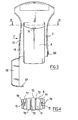
- FIG. 1 shows a distribution and application device 1 according to the invention, comprising a body 2 on which an organ is mounted. 3 and a product tank 4.
- the body 2 is made of thermoplastic material. In variant, it can be made of any other material, for example metal.
- the body 2 comprises in the upper part a head 6 forming a housing 7 extending along an axis X and intended to receive the application element 3.
- the housing 7 has a perforated bottom wall 8 and having a shape substantially concave upwards, as can be seen in FIG.
- the head 6 has two lateral portions 10 and 11 traversed by respective openings 12 and 13, substantially cylindrical axis X.
- the housing 7 is open at its upper part so as to leave unobstructed substantially one half of the applicator member 3, as can be seen in FIG.
- the body 2 further comprises, in the example under consideration, below the head 6, two arms 15 extending along a Y axis perpendicular to the X axis.
- the reservoir 4 is placed in a detachable manner between the two arms 15, as explained later.
- the application member 3 comprises a core 19 comprising two cylinders coaxial interior 20 and outer 21, of axis X.
- the inner cylinder 20 may comprise a first relief, for example a longitudinal rib 22, engaging in a second relief of complementary shape, by a groove 23, of the outer cylinder 21, as illustrated in FIG. immobilizing the cylinders 20 and 21 in rotation when assembled.
- the inner cylinder 20 may comprise a perforated transverse wall 27, inside, perpendicular to the X axis and having a toothed surface 28 at the level of the day.
- the cylinder 20 deflects on both sides of the transverse wall 27 two housings 30 and 31 for receiving respectively two fasteners 33 and 34, made for example of thermoplastic material.
- the fasteners 33 and 34 comprise in the example considered each a cylindrical body 36 of X axis provided with lugs 39, as illustrated in FIG. concerning the fastener 34.
- Each fastener 33 or 34 is introduced through an opening 12 or 13 corresponding to the head 6, in the associated housing 30 or 31 of the core 19, so to allow the application member 3 to be held rotatably about the X axis.
- the fasteners 33 and 34 can be locked on the portions 10 and 11 by the cooperation of the lugs 39 in recesses 40 made on these side portions 10 and 11.
- the locking of the fasteners 33 and 34 on these portions 10 and 11 can be obtained for example by a rotation of the members 33 and 34 by a predetermined angle, for example a quarter turn.
- This rotation can be performed for example by means of a specific tool cooperating with a groove 45 made on a head 46 of the fastener 33, 34, as shown in Figure 7.
- the fasteners 33 and 34 can be unlocked and removed, if applicable.
- the fastener 33 carries an electric motor 50 provided with an element 51, in the form of a pinion in the example.
- This body 51 is engaged on the toothed surface 28 of the cylinder 20 to drive the application member 3 rotated about the axis X.
- the motor 50 directly drives the body application 3.
- the motor 50 is powered by a power supply, for example one or several batteries or accumulators 54 housed in a compartment 55 made in a 56 cover hinged on the body 2.
- This cover 56 may comprise a tab of closing 57 adapted to snap into a recess 58 made on the body 2, as one can see it in figure 3.
- the power supply is connected to the motor 50 via wires 60 housed in an arm 15 of the body 2, as illustrated in FIG. 2.
- the device 1 may comprise a switch 61 for controlling the operation of the motor 50, this switch 61 being disposed on one of the arms 15 and covered for example by an elastically deformable wall 62.
- the outer cylinder 21 has on its outer face a plurality of reliefs 65, the latter being constituted in the example in question by bosses.
- the applicator member 3 further comprises an outer wall 25 capable of loading into the product contained in the tank 4 and having in the example considered a substantially ellipsoidal shape, elongate with axis X.
- the outer wall 25 is for example in the form of a sleeve elastically deformable, made of elastomer.
- the outer wall 25 has at its ends flanges 26 immobilizing it axially on the core 19.
- the outer wall 25 could be fixed on the core 19 by any other means, for example by gluing.
- the tank 4 has a variable internal volume and comprises two elastically deformable walls 70 arranged facing one of the other, as shown in Figure 4.
- the tank 4 has an upper wall 71, concave upwards, and provided with one or more outlets 72.
- this or these outlet orifices 72 may be under the form of slots, for example parallel.
- the outlet orifice (s) could be any other form, being for example circular.
- the reservoir 4 may furthermore comprise a filling orifice 73, for example example opposite the outlet or openings.
- the filling orifice 73 may for example be closed by a screw cap, snapped, or on a neck 74 of the tank 4, as illustrated in FIG.
- the filling orifice 73 can be closed by a cap engaging, for example by friction, in an inner skirt 75 of the tank 4.
- the tank 4 has on its lateral sides two longitudinal grooves 77 intended to engage each on a longitudinal rib 78 performed on an arm 15, so as to guide the reservoir 4 during the establishment of the latter on the body 2, as illustrated in Figure 4.
- the lid 56 is in the open position during the installation of the reservoir on the body 2, as shown in Figure 3.
- This cover 56 is brought into position closed once the reservoir 4 in place on the body 2, as shown in Figure 1.
- the upper wall 71 of the tank 4 is positioned in the a journey of the bottom wall 8 of the housing 7.
- This upper wall 71 of the tank 4 is shaped to match the outer wall 25 of the implementing body 3.
- the outer wall 25 of the applicator member 3 is applied to the wall upper tank 71 with some constraint, so that it can be loaded with the product directly from the outlet orifice (s) 72 and close this or these in the absence of use, which improves the conservation of the product.
- the tank 4 may optionally include a closure element of the or outlets 72, for example a removable film, to be removed before the first use.
- the reservoir 4 contains a cosmetic product, for example a gel or a liquid, especially a low viscosity liquid.
- a cosmetic product for example a gel or a liquid, especially a low viscosity liquid.
- the user starts the motor 50, which causes rotation of the applicator member 3 about the X axis.
- the wall 25 of the application member 3 is compressed, and can come into contact with the bosses 65.
- the outer wall 25 may be loaded with product through the orifice (s) outlet 72 of the tank 4, pressing on the walls 70.
- the applicator member 3 being removably mounted on the container, it it is possible, if necessary, to replace it with another having for example bosses 65 of different shape and / or size, so as to provide a different massage effect.
- the device 1 can thus be provided with a plurality of application members 3 in a kit.
- the wall outer member 25 of the applicator member 3 has a shape other than a shape ellipsoidal elongated.
- the device 85 may comprise an organ 80 having an outer wall 80a having a shape substantially spherical.
- This applicator member 80 has housings 30 and 31 enabling it to be accommodate not shown fasteners.
- the applicator member 80 is mounted on a support 81 traversed by an orifice 82 single output.
- the support 81 is fixed on a neck 87 of a container 86 forming a reservoir for the product.
- an application member with a soul consisting for example of a single cylinder, and the outer wall 25, in particular rigid or no, may carry reliefs, in particular bosses, intended to provide an effect of massage.
Landscapes
- Health & Medical Sciences (AREA)
- Animal Behavior & Ethology (AREA)
- Pain & Pain Management (AREA)
- Physical Education & Sports Medicine (AREA)
- Rehabilitation Therapy (AREA)
- Life Sciences & Earth Sciences (AREA)
- Epidemiology (AREA)
- General Health & Medical Sciences (AREA)
- Public Health (AREA)
- Veterinary Medicine (AREA)
- Coating Apparatus (AREA)
- Massaging Devices (AREA)
- Cosmetics (AREA)
- Application Of Or Painting With Fluid Materials (AREA)
Abstract
Description
La présente invention a pour objet un dispositif de distribution et d'application d'un produit, notamment un produit cosmétique et/ou de soin.The subject of the present invention is a device for dispensing and applying a product, especially a cosmetic and / or care product.
Par « produit cosmétique », on entend au sens de la présente invention un produit tel que défmi dans la Directive 93/35/CEE du 14 juin 1993 modifiant la Directive 76/768/CEE.By "cosmetic product" is meant within the meaning of the present invention a product as defined in Directive 93/35 / EEC of 14 June 1993 amending Directive 76/768 / EEC.
On connaít par le brevet US 3 994 290 un dispositif de massage comportant une unité de massage rotative entraínée en rotation par un moteur et portant une pluralité de billes montées librement dessus. Du produit contenu dans un récipient peut être distribué vers les billes via des conduits.No. 3,994,290 discloses a massage device comprising a rotary massage unit driven in rotation by a motor and carrying a plurality of balls mounted freely on it. Product contained in a container may be dispensed to the beads via conduits.
On connaít également par le brevet US 5 725 483 un dispositif de massage comportant un moteur entraínant en rotation une pluralité d'éléments hémisphériques de massage. Ce dispositif est pourvu d'un réservoir de produit pouvant alimenter, grâce à une pompe, des brosses disposées à la périphérie des éléments hémisphériques, à travers des orifices situés à la base de ces brosses.Also known from US Patent 5,725,483 a massage device comprising a motor rotating a plurality of hemispherical elements of massage. This device is provided with a reservoir of product that can feed, thanks to a pump, brushes arranged at the periphery of the hemispherical elements, through holes at the base of these brushes.
On connaít encore par le brevet US 5 105 802 un dispositif comportant une tête rotative portant une pluralité de billes et entraínées par un moteur. La tête rotative défmit un espace dans lequel du produit peut être distribué au contact des billes. Celles-ci sont montées de manière rotative sur la tête et peuvent être entraínées en rotation sur elles-mêmes par le moteur. Les billes sont ainsi animées d'un mouvement résultant de la composition de deux rotations autour d'axes distincts.US Pat. No. 5,105,802 discloses a device comprising a rotary head carrying a plurality of balls and driven by a motor. The rotating head defines a space in which product can be distributed in contact with the balls. These are rotatably mounted on the head and can be rotated on themselves by the engine. The balls are thus animated with a movement resulting from the composition of two rotations around distinct axes.
La demande DE 20 11 173 décrit un dispositif de massage comportant des rouleaux montés de manière pivotante sur un support, lequel est entraíné en rotation par accouplement d'un moteur sur une portion du support. Les rouleaux sont ainsi rotatifs autour de deux axes de rotation parallèles et distincts.DE 20 11 173 discloses a massage device comprising rollers pivotally mounted on a support, which is rotated by coupling a motor to a portion of the support. The rollers are thus rotary around two parallel and distinct axes of rotation.
La demande EP 0 940 100 divulgue une paire de ciseaux comportant des rouleaux fixés sur chaque branche de la paire. Les rouleaux sont rotatifs autour de leur propre axe de symétrie ainsi qu'autour de l'axe d'articulation de la paire de ciseaux.Application EP 0 940 100 discloses a pair of scissors comprising rolls fixed on each branch of the pair. The rollers are rotatable around their own axis of symmetry as well as around the axis of articulation of the pair of scissors.
Les dispositifs précités présentent des structures relativement complexes. The aforementioned devices have relatively complex structures.
La présente invention vise notamment à fournir un dispositif de distribution et d'application d'un produit qui présente une structure relativement simple et qui facilite la distribution du produit.The present invention aims in particular to provide a distribution device and the application of a product which has a relatively simple structure and which facilitates the product distribution.
L'invention répond notamment à ce besoin grâce à un dispositif de distribution et d'application d'un produit contenu dans un réservoir, ce dispositif comportant :
- un organe d'application comportant une paroi extérieure apte à se charger en produit contenu dans le réservoir en vue de le distribuer, cette paroi pouvant tourner autour d'un unique axe de rotation,
- un moteur d'entraínement de l'organe d'application en rotation autour dudit axe.
- an applicator member comprising an outer wall capable of being loaded with the product contained in the reservoir for the purpose of dispensing it, this wall being able to rotate about a single axis of rotation,
- a drive motor of the application member rotated about said axis.
Grâce à l'invention, l'entraínement en rotation de la paroi extérieure de l'organe d'application peut être assuré par un nombre réduit de pièces car cette rotation s'effectue autour d'un unique axe de rotation.Thanks to the invention, the rotational drive of the outer wall of the application member can be provided by a reduced number of parts because this rotation is performed around a single axis of rotation.
Ainsi, le dispositif peut présenter une structure relativement simple et un encombrement réduit.Thus, the device can have a relatively simple structure and a small footprint.
Par ailleurs, la paroi extérieure de l'organe d'application peut être disposée à proximité du réservoir de produit, ce qui permet d'éviter la présence notamment de conduits spécifiques pour transporter du produit du réservoir vers cette paroi extérieure.Furthermore, the outer wall of the applicator member may be arranged to proximity of the product tank, which makes it possible to avoid the presence of specific conduits for conveying product from the tank to this outer wall.
Le moteur peut entraíner l'organe d'application en rotation directement ou indirectement, par exemple par l'intermédiaire d'organes de transmission de mouvement, afm par exemple de réduire la vitesse de rotation et augmenter le couple.The motor can drive the rotating application member directly or indirectly, for example by means of motion transmission members, for example to reduce the speed of rotation and increase the torque.
Dans un exemple de mise en oeuvre de l'invention, la paroi extérieure présente une symétrie sensiblement de révolution autour d'un axe de symétrie, la paroi extérieure pouvant être rotative autour de cet axe de symétrie.In an exemplary implementation of the invention, the outer wall has a symmetry substantially of revolution around an axis of symmetry, the outer wall which can be rotatable around this axis of symmetry.
En variante, l'organe d'application peut être rotatif autour d'un axe de rotation distinct de cet axe de symétrie.In a variant, the applicator member may be rotatable about an axis of rotation distinct from this axis of symmetry.
La paroi extérieure de l'organe d'application peut présenter une forme sensiblement ellipsoïdale allongée ou, en variante, une forme sensiblement ellipsoïdale aplatie.The outer wall of the applicator member may have a shape substantially ellipsoidal elongate or, alternatively, a substantially ellipsoidal shape flattened.
Dans un autre exemple de mise en oeuvre de l'invention, la paroi extérieure présente une forme sensiblement sphérique. In another embodiment of the invention, the outer wall has a substantially spherical shape.
La paroi extérieure peut être élastiquement déformable, étant réalisée par exemple en élastomère.The outer wall may be elastically deformable, being made by example elastomer.
L'organe d'application peut comporter une âme sur laquelle est rapportée la paroi extérieure. Cette âme peut comporter par exemple une surface pourvue de reliefs et la paroi extérieure peut être apte à se déformer lors de l'application pour venir au contact des reliefs. Ces derniers permettent de produire un effet de massage lorsque l'organe d'application est en contact avec la surface à traiter, ce qui peut entre autre faciliter la pénétration du produit dans la peau et favoriser son action.The applicator member may comprise a core on which the outer wall. This core may comprise for example a surface provided with reliefs and the outer wall can be adapted to deform during application to come into contact landforms. These allow to produce a massage effect when the organ application is in contact with the surface to be treated, which can, among other things, facilitate the penetration of the product into the skin and promote its action.
La paroi extérieure peut, en variante, être rigide.The outer wall may, alternatively, be rigid.
Dans un exemple de mise en oeuvre de l'invention, la paroi extérieure comporte des reliefs, lesquels peuvent comporter par exemple des bossages.In an exemplary implementation of the invention, the outer wall comprises reliefs, which may comprise for example bosses.
Dans un exemple de mise en oeuvre de l'invention, l'organe d'application comporte au moins un logement apte à recevoir un organe de fixation de l'organe d'application sur le dispositif.In an exemplary implementation of the invention, the application member has at least one housing adapted to receive an organ fixing member application on the device.
L'organe d'application peut comporter au moins une surface dentée apte à être couplée au moteur. Cette surface dentée peut être située dans le logement précité et le moteur peut s'étendre au moins partiellement dans le logement, ce qui permet de réduire l'encombrement du dispositif.The applicator member may comprise at least one toothed surface capable of being coupled to the engine. This toothed surface may be located in the aforementioned housing and the motor can extend at least partially into the housing, thereby reducing the size of the device.
Le logement précité peut s'étendre sensiblement parallèlement à l'axe de rotation de l'organe d'application.The aforementioned housing may extend substantially parallel to the axis of rotation of the application member.
Dans un exemple de mise en oeuvre de l'invention, l'organe d'application comporte une âme comprenant des cylindres intérieur et extérieur, le cylindre intérieur comportant une surface dentée et le cylindre extérieur des reliefs sur sa surface extérieure.In an exemplary implementation of the invention, the application member has a core comprising inner and outer cylinders, the inner cylinder having a toothed surface and the outer cylinder of the reliefs on its outer surface.
Avantageusement, l'organe d'application est monté de manière amovible sur le dispositif.Advantageously, the application member is removably mounted on the device.
Dans un exemple de mise en oeuvre de l'invention, le réservoir de produit comporte au moins un orifice de sortie et la paroi extérieure de l'organe d'application est disposée en contact ou sensiblement en contact de l'orifice de sortie.In an exemplary implementation of the invention, the product reservoir comprises at least one outlet orifice and the outer wall of the applicator member is disposed in contact or substantially in contact with the outlet.
Le réservoir peut comporter une paroi sur laquelle débouche l'orifice de sortie, cette paroi épousant sensiblement la forme d'au moins une portion de l'organe d'application. Cette paroi du réservoir peut par exemple être concave vers l'extérieur. Lorsque la paroi extérieure de l'organe d'application est élastiquement déformable, cette paroi extérieure vient avantageusement s'appliquer sur l'orifice de sortie avec une certaine contrainte. Ainsi, lorsque le dispositif n'est pas utilisé, la paroi extérieure de l'organe d'application sert à obturer cet orifice de sortie.The reservoir may comprise a wall on which the outlet orifice opens, this wall substantially conforming to the shape of at least a portion of the organ application. This wall of the tank may for example be concave towards the outside. When the outer wall of the applicator member is elastically deformable, this outer wall is advantageously applied to the outlet orifice with a certain constraint. Thus, when the device is not used, the outer wall of the organ application is used to seal this outlet.
Le réservoir peut présenter un volume intérieur variable et comporter au moins une paroi élastiquement déformable pour réduire le volume intérieur, notamment deux parois élastiquement déformables en regard l'une de l'autre.The tank may have a variable internal volume and comprise at least an elastically deformable wall to reduce the internal volume, in particular two elastically deformable walls facing one another.
Le réservoir peut être agencé pour être monté de manière amovible sur le dispositif de manière à permettre, lorsque le réservoir est vidé, de le remplacer par un autre ou de le retirer pour le remplir, lorsque le réservoir comporte un orifice de remplissage.The reservoir can be arranged to be removably mounted on the device so as to allow, when the tank is emptied, to replace it with a the other, or to remove it to fill it, when the tank has a filling.
Le dispositif peut comporter un interrupteur relié au moteur et disposé par exemple sous une paroi élastiquement déformable du dispositifThe device may comprise a switch connected to the motor and arranged by example under an elastically deformable wall of the device
Le dispositif peut comporter un compartiment pour loger au moins une pile, ce compartiment étant par exemple articulé sur le reste du dispositifThe device may comprise a compartment for housing at least one battery, this compartment being for example articulated on the rest of the device
Le dispositif peut ne comporter qu'un unique organe d'application.The device may comprise only one application member.
Dans un exemple de mise en oeuvre de l'invention, l'organe d'application tourne par rapport au réservoir.In an exemplary implementation of the invention, the application member turns relative to the tank.
Ce réservoir peut par exemple être à l'extérieur de l'organe d'application.This reservoir may for example be outside the application member.
Le produit peut être un produit cosmétique, par exemple un gel ou un liquide, notamment un liquide à faible viscosité.The product may be a cosmetic product, for example a gel or a liquid, especially a low viscosity liquid.
L'invention a encore pour objet, selon un autre de ses aspects, un kit comportant :
- un dispositif tel que défini ci-dessus,
- une pluralité d'organes d'application, ces organes d'application étant agencés pour être montés sélectivement et de manière amovible sur le dispositif
- a device as defined above,
- a plurality of application members, these application members being arranged to be mounted selectively and removably on the device
Les organes d'application peuvent comporter des reliefs différents pouvant s'appliquer, directement ou indirectement, sur une surface à traiter. Ainsi, selon par exemple l'effet de massage souhaité, l'utilisateur sélectionne l'organe d'application comportant des reliefs adaptés à obtenir cet effet de massage.The application members may comprise different reliefs that may apply, directly or indirectly, to a surface to be treated. So, according to example the desired massage effect, the user selects the application member having reliefs adapted to achieve this massage effect.
L'invention a encore pour objet, selon un autre de ses aspects, un organe d'application destiné à être monté de manière rotative et amovible sur un dispositif tel que précité. Another subject of the invention is, according to another of its aspects, an organ application intended to be rotatably and removably mounted on a device such as supra.
L'invention a encore pour objet, selon un autre de ses aspects, un réservoir de produit destiné à être monté sur le dispositif tel que précité, le réservoir comportant une paroi concave vers l'extérieur et sur laquelle débouche au moins un orifice de sortie.Another object of the invention is, according to another of its aspects, a reservoir of product intended to be mounted on the device as mentioned above, the reservoir comprising a concave wall to the outside and on which opens at least one outlet port.
L'invention a encore pour objet, selon un autre de ses aspects, un procédé pour appliquer un produit sur une surface du corps, caractérisé par le fait qu'il comporte les étapes suivantes :
- fournir un kit tel que défini plus haut,
- sélectionner un organe d'application,
- monter l'organe d'application ainsi sélectionné sur le dispositif,
- appliquer du produit sur le corps à l'aide de cet organe d'application.
- provide a kit as defined above,
- select an application organ,
- mount the application member thus selected on the device,
- apply product on the body using this application member.
L'invention a encore pour objet, selon un autre de ses aspects, un dispositif de distribution et d'application d'un produit contenu dans un réservoir, le dispositif comportant :
- un organe d'application rotatif comportant une paroi extérieure élastiquement déformable apte à se charger en produit contenu dans le réservoir,
- un moteur d'entraínement de l'organe d'application.
- a rotary application member comprising an elastically deformable outer wall capable of being loaded with the product contained in the reservoir,
- a drive motor of the application member.
L'organe d'application comporte avantageusement une âme présentant des reliefs, la paroi élastiquement déformable étant apte à se déformer pour venir au contact des reliefs.The application member advantageously comprises a core having reliefs, the elastically deformable wall being able to deform to come into contact landforms.
L'invention a encore pour objet, selon un autre de ses aspects, un dispositif de distribution et d'application d'un produit contenu dans un réservoir, le dispositif comportant :
- un organe d'application rotatif comportant une paroi extérieure ayant une forme sensiblement ellipsoïdale allongée et apte à se charger en produit contenu dans le réservoir,
- un moteur d'entraínement de l'organe d'application.
- a rotary application member comprising an outer wall having a substantially ellipsoidal elongated shape and able to be loaded with the product contained in the reservoir,
- a drive motor of the application member.
L'invention a encore pour objet, selon un autre de ses aspects, un dispositif de distribution et d'application d'un produit contenu dans un réservoir, le dispositif comportant :
- un organe d'application rotatif comportant une paroi extérieure apte à se charger en produit contenu dans le réservoir, l'organe d'application comportant en outre au moins un logement pour recevoir un organe de fixation de l'organe d'application sur le dispositif,
- un moteur d'entraínement de l'organe d'application.
- a rotary application member having an outer wall adapted to be loaded with product contained in the reservoir, the applicator member further comprising at least one housing for receiving a fastener of the applicator member on the device ,
- a drive motor of the application member.
L'invention a encore pour objet, selon un autre de ses aspects, un dispositif de distribution et d'application d'un produit, le dispositif comportant :
- un réservoir de volume intérieur variable contenant du produit et comportant au moins une paroi élastiquement déformable permettant de réduire le volume intérieur,
- un organe d'application rotatif comportant une paroi extérieure apte à se charger en produit contenu dans le réservoir,
- un moteur d'entraínement de l'organe d'application.
- a reservoir of variable internal volume containing product and comprising at least one elastically deformable wall making it possible to reduce the internal volume,
- a rotary application member comprising an outer wall that can be loaded with the product contained in the reservoir,
- a drive motor of the application member.
Le dispositif peut ainsi être dépourvu par exemple de pompe pour distribuer le produit contenu dans le réservoir.The device may thus be devoid of, for example, a pump for dispensing the product contained in the tank.
L'invention pourra être mieux comprise à la lecture de la description détaillée qui va suivre, d'exemples de mise en oeuvre non limitatifs de celle-ci, et à l'examen du dessin annexé, sur lequel :
- la figure 1 représente, schématiquement et partiellement, en élévation, un dispositif de distribution et d'application conforme à l'invention,
- la figure 2 représente, schématiquement et partiellement, en coupe axiale, le dispositif de la figure 1,
- la figure 3 représente, schématiquement et partiellement, le dispositif de la figure 1, le réservoir de produit étant partiellement retiré,
- la figure 4 est une vue schématique et partielle, en coupe suivant IV-IV, du dispositif de la figure 3,
- les figures 5
et 6 représentent, schématiquement et partiellement, un réservoir de produit conforme à deux exemples de mise en oeuvre de l'invention, - la figure 7 est une vue schématique et partielle, en perspective, d'un organe de fixation du dispositif de la figure 1,
- la figure 8 est une vue schématique et partielle, en coupe transversale, de l'organe d'application du dispositif de la figure 1,
- la figure 9 représente, schématiquement et partiellement, en coupe transversale, l'engrènement de l'axe du moteur avec l'organe d'application dans une variante de réalisation,
- la figure 10 représente, schématiquement et partiellement, en coupe longitudinale, l'organe d'application du dispositif de la figure 1, lorsque cet organe d'application est appliqué sur une surface à traiter, et
- la figure 11 représente, schématiquement et partiellement, un dispositif de distribution et d'application conforme à un autre exemple de mise en oeuvre de l'invention.
- FIG. 1 represents, schematically and partially, in elevation, a distribution and application device according to the invention,
- FIG. 2 represents, schematically and partially, in axial section, the device of FIG.
- FIG. 3 represents, schematically and partially, the device of FIG. 1, the product reservoir being partially removed,
- FIG. 4 is a diagrammatic and partial view, in section along IV-IV, of the device of FIG. 3,
- Figures 5 and 6 show, schematically and partially, a product tank according to two examples of implementation of the invention,
- FIG. 7 is a diagrammatic and partial view, in perspective, of a fastener of the device of FIG. 1,
- FIG. 8 is a diagrammatic and partial view, in cross section, of the applicator member of the device of FIG. 1,
- FIG. 9 represents, schematically and partially, in cross section, the engagement of the axis of the motor with the applicator member in a variant embodiment;
- FIG. 10 represents, schematically and partially, in longitudinal section, the applicator member of the device of FIG. 1, when this applicator member is applied to a surface to be treated, and
- Figure 11 shows, schematically and partially, a dispensing device and application according to another embodiment of the invention.
On a représenté sur la figure 1 un dispositif de distribution et d'application 1
conforme à l'invention, comportant un corps 2 sur lequel sont montés un organe
d'application 3 et un réservoir de produit 4.FIG. 1 shows a distribution and
Dans l'exemple considéré, le corps 2 est réalisé en matière thermoplastique. En
variante, celui-ci peut être réalisé en tout autre matériau, par exemple en métal.In the example considered, the
Le corps 2 comporte en partie supérieure une tête 6 formant un logement 7
s'étendant suivant un axe X et destiné à recevoir l'élément d'application 3.The
Le logement 7 comporte une paroi de fond 8 ajourée et ayant une forme
sensiblement concave vers le haut, comme on peut le voir sur la figure 2.The
La tête 6 comporte deux portions latérales 10 et 11 traversées par des
ouvertures respectives 12 et 13, sensiblement cylindriques d'axe X.The
Le logement 7 est ouvert à sa partie supérieure de manière à laisser dégagée
sensiblement une moitié de l'organe d'application 3, comme on peut le voir sur la figure 1.The
Le corps 2 comporte en outre, dans l'exemple considéré, en dessous de la tête
6, deux bras 15 s'étendant suivant un axe Y perpendiculaire à l'axe X.The
Le réservoir 4 est mis en place de manière amovible entre les deux bras 15,
comme expliqué dans la suite.The
L'organe d'application 3 comporte une âme 19 comprenant deux cylindres
intérieur 20 et extérieur 21 coaxiaux, d'axe X.The
Le cylindre intérieur 20 peut comporter un premier relief, par exemple une
nervure longitudinale 22, s'engageant dans un second relief de forme complémentaire, par
exemple une rainure 23, du cylindre extérieur 21, comme illustré sur la figure 8, afm
d'immobiliser les cylindres 20 et 21 en rotation lorsqu'ils sont assemblés. The
Le cylindre intérieur 20 peut comporter une paroi transversale ajourée 27,
intérieure, perpendiculaire à l'axe X et présentant une surface dentée 28 au niveau de
l'ajour.The
Le cylindre 20 défmit de part et d'autre de la paroi transversale 27 deux
logements 30 et 31 permettant de recevoir respectivement deux organes de fixation 33 et
34, réalisés par exemple en matière thermoplastique.The
Les organes de fixation 33 et 34 comportent dans l'exemple considéré chacun
un corps cylindrique 36 d'axe X pourvu d'ergots 39, comme illustré sur la figure 7 en ce
qui concerne l'organe de fixation 34.The
Chaque organe de fixation 33 ou 34 est introduit, à travers une ouverture 12 ou
13 correspondante de la tête 6, dans le logement associé 30 ou 31 de l'âme 19, de manière
à permettre le maintien de l'organe d'application 3 de manière rotative autour de l'axe X.Each
Les organes de fixation 33 et 34 peuvent être verrouillés sur les portions
latérales 10 et 11 grâce à la coopération des ergots 39 dans des évidements 40 réalisés sur
ces portions latérales 10 et 11.The
Dans l'exemple décrit, après le verrouillage, les organes de fixation 33 et 34
sont bloqués en rotation par rapport aux portions 10 et 11.In the example described, after locking, the
Le verrouillage des organes de fixation 33 et 34 sur ces portions 10 et 11 peut
être obtenu par exemple par une rotation des organes 33 et 34 d'un angle prédéterminé,
par exemple d'un quart de tour.The locking of the
Cette rotation peut être effectuée par exemple au moyen d'un outil spécifique
coopérant avec une rainure 45 réalisée sur une tête 46 de l'organe de fixation 33, 34,
comme illustré sur la figure 7.This rotation can be performed for example by means of a specific tool
cooperating with a
Les organes de fixation 33 et 34 peuvent être déverrouillés et retirés, le cas
échéant.The
L'organe de fixation 33 porte un moteur électrique 50 pourvu d'un organe
d'entraínement 51, sous la forme d'un pignon dans l'exemple considéré. Cet organe
d'entraínement 51 vient s'engrener sur la surface dentée 28 du cylindre 20 afin d'entraíner
l'organe d'application 3 en rotation autour de l'axe X.The fastener 33 carries an
Dans l'exemple considéré, le moteur 50 entraíne directement l'organe
d'application 3. In the example considered, the
En variante, comme illustré sur la figure 9, il est possible d'interposer entre le
pignon 51 du moteur 50 et une surface dentée 28' de l'organe d'application 3, un satellite
53.Alternatively, as illustrated in FIG. 9, it is possible to interpose between the
Le moteur 50 est alimenté par une alimentation électrique, par exemple une ou
plusieurs piles ou accumulateurs 54 logés dans un compartiment 55 réalisé dans un
couvercle 56 articulé sur le corps 2. Ce couvercle 56 peut comporter une patte de
fermeture 57 apte à s'encliqueter dans un évidement 58 réalisé sur le corps 2, comme on
peut le voir sur la figure 3.The
L'alimentation électrique est reliée au moteur 50 par l'intermédiaire de fils 60
logés dans un bras 15 du corps 2, comme illustré sur la figure 2.The power supply is connected to the
Le dispositif 1 peut comporter un interrupteur 61 pour commander le
fonctionnement du moteur 50, cet interrupteur 61 étant disposé sur l'un des bras 15 et
recouvert par exemple par une paroi élastiquement déformable 62.The
Le cylindre extérieur 21 comporte sur sa face extérieure une pluralité de reliefs
65, ces derniers étant constitués dans l'exemple considéré par des bossages.The
L'organe d'application 3 comporte en outre une paroi extérieure 25 apte à se
charger en produit contenu dans le réservoir 4 et ayant dans l'exemple considéré une
forme sensiblement ellipsoïdale, allongée d'axe X.The
La paroi extérieure 25 se présente par exemple sous la forme d'un manchon
élastiquement déformable, réalisé en élastomère.The
Dans l'exemple considéré, la paroi extérieure 25 comporte à ses extrémités des
collerettes 26 l'immobilisant axialement sur l'âme 19.In the example under consideration, the
La paroi extérieure 25 pourrait être fixée sur l'âme 19 par tout autre moyen,
par exemple par collage.The
Comme on peut le voir sur la figure 10, lorsque l'organe d'application 3 est
amené au contact d'une surface S à traiter, par exemple la peau, la paroi élastiquement
déformable 25 est localement comprimée, de sorte qu'elle vient en appui sur les bossages
65. Ces derniers exercent sur la surface S un effet de massage à travers la paroi extérieure
25, lors de la rotation de l'organe d'application 3.As can be seen in FIG. 10, when the
Dans l'exemple considéré, le réservoir 4 présente un volume intérieur variable
et comporte deux parois élastiquement déformables 70 disposées en regard l'une de
l'autre, comme illustré à la figure 4. In the example considered, the
Le réservoir 4 comporte une paroi supérieure 71, concave vers le haut, et
pourvue d'un ou de plusieurs orifices de sortie 72.The
Comme illustré sur la figure 4, ce ou ces orifices de sortie 72 peuvent être sous
la forme de fentes, par exemple parallèles. En variante, le ou les orifices de sortie
pourraient présenter toute autre forme, étant par exemple circulaires.As illustrated in FIG. 4, this or these
Le réservoir 4 peut comporter en outre un orifice de remplissage 73, par
exemple à l'opposé du ou des orifices de sortie.The
L'orifice de remplissage 73 peut par exemple être fermé par un bouchon vissé,
encliqueté, ou sur un col 74 du réservoir 4, comme illustré sur la figure 5.The filling
En variante, comme illustré sur la figure 6, l'orifice de remplissage 73 peut
être obturé par un bouchon s'engageant, par exemple par friction, dans une jupe intérieure
75 du réservoir 4.Alternatively, as illustrated in FIG. 6, the filling
Dans l'exemple considéré, le réservoir 4 comporte sur ses côtés latéraux deux
rainures longitudinales 77 destinées à s'engager chacune sur une nervure longitudinale 78
réalisée sur un bras 15, de manière à guider le réservoir 4 lors de la mise en place de celui-ci
sur le corps 2, comme illustré sur la figure 4.In the example considered, the
Le couvercle 56 est en position ouverte lors de la mise en place du réservoir
sur le corps 2, comme illustré sur la figure 3. Ce couvercle 56 est ramené en position
fermée une fois le réservoir 4 en place sur le corps 2, comme illustré sur la figure 1.The
Lorsque le réservoir 4 est en place sur le corps 2, la paroi supérieure 71 du
réservoir 4 vient se positionner dans l'ajour de la paroi de fond 8 du logement 7. Cette
paroi supérieure 71 du réservoir 4 est conformée pour épouser la paroi extérieure 25 de
l'organe d'application 3.When the
La paroi extérieure 25 de l'organe d'application 3 vient s'appliquer sur la paroi
supérieure 71 du réservoir 4 avec une certaine contrainte, de manière à pouvoir être
chargée avec le produit provenant directement du ou des orifices de sortie 72 et obturer ce
ou ces derniers en l'absence d'utilisation, ce qui améliore la conservation du produit.The
Le réservoir 4 peut le cas échéant comporter un élément d'obturation du ou
des orifices de sortie 72, par exemple un film amovible, à retirer avant la première
utilisation.The
Le réservoir 4 contient un produit cosmétique, par exemple un gel ou un
liquide, notamment un liquide de faible viscosité. The
Pour appliquer du produit, l'utilisateur met en marche le moteur 50, ce qui
provoque la rotation de l'organe d'application 3 autour de l'axe X.To apply the product, the user starts the
Au contact de la surface S à traiter, comme illustré sur la figure 10, la paroi
extérieure 25 de l'organe d'application 3 est comprimée, et peut venir au contact des
bossages 65.In contact with the surface S to be treated, as illustrated in FIG. 10, the
Ces derniers produisent un effet de massage sur la surface S.These produce a massage effect on the surface S.
La paroi extérieure 25 peut être chargée en produit à travers le ou les orifices
de sortie 72 du réservoir 4, en appuyant sur les parois 70.The
L'organe d'application 3 étant monté de manière amovible sur le récipient, il
est possible, le cas échéant, de le remplacer par un autre ayant par exemple des bossages
65 de forme et/ou de taille différentes, de manière à procurer un effet de massage différent.The
Le dispositif 1 peut ainsi être fourni avec une pluralité d'organes d'application
3 dans un kit.The
Bien entendu, on ne sort pas du cadre de la présente invention lorsque la paroi
extérieure 25 de l'organe d'application 3 présente une forme autre qu'une forme
ellipsoïdale allongée.Of course, it is not beyond the scope of the present invention when the wall
Comme illustré sur la figure 11, le dispositif 85 peut comporter un organe
d'application 80 ayant une paroi extérieure 80a présentant une forme sensiblement
sphérique.As illustrated in FIG. 11, the
Cet organe d'application 80 comporte des logements 30 et 31 permettant d'y
loger des organes de fixation non représentés.This
L'organe d'application 80 est monté sur un support 81 traversé par un orifice
de sortie 82 unique.The
Le support 81 est fixé sur un col 87 d'un récipient 86 formant un réservoir
pour le produit.The
Bien entendu, l'invention n'est pas limitée aux exemples de mise en oeuvre qui viennent d'être décrits.Of course, the invention is not limited to the implementation examples which have just been described.
Il est par exemple possible de prévoir un organe d'application avec une âme
constituée par exemple d'un seul cylindre, et la paroi extérieure 25, notamment rigide ou
non, peut porter des reliefs, notamment des bossages, destinés à procurer un effet de
massage. It is for example possible to provide an application member with a soul
consisting for example of a single cylinder, and the
Dans toute la description, y compris les revendications, l'expression « comportant un » doit être comprise comme étant synonyme de « comportant au moins un », sauf si le contraire est spécifié.Throughout the description, including the claims, the expression "Comprising one" must be understood as being synonymous with "comprising at least a ", unless the opposite is specified.
Claims (31)
Applications Claiming Priority (2)
| Application Number | Priority Date | Filing Date | Title |
|---|---|---|---|
| FR0404854 | 2004-05-05 | ||
| FR0404854A FR2869881B1 (en) | 2004-05-05 | 2004-05-05 | DEVICE FOR DISTRIBUTING AND APPLYING A PRODUCT, IN PARTICULAR A COSMETIC AND / OR CARE PRODUCT |
Publications (2)
| Publication Number | Publication Date |
|---|---|
| EP1593363A1 true EP1593363A1 (en) | 2005-11-09 |
| EP1593363B1 EP1593363B1 (en) | 2010-08-04 |
Family
ID=34942587
Family Applications (1)
| Application Number | Title | Priority Date | Filing Date |
|---|---|---|---|
| EP05300346A Not-in-force EP1593363B1 (en) | 2004-05-05 | 2005-04-29 | Device for distribution and application of products, especially cosmetic products |
Country Status (6)
| Country | Link |
|---|---|
| US (1) | US7775735B2 (en) |
| EP (1) | EP1593363B1 (en) |
| AT (1) | ATE476170T1 (en) |
| DE (1) | DE602005022648D1 (en) |
| ES (1) | ES2349289T3 (en) |
| FR (1) | FR2869881B1 (en) |
Cited By (4)
| Publication number | Priority date | Publication date | Assignee | Title |
|---|---|---|---|---|
| FR2886542A1 (en) * | 2005-06-03 | 2006-12-08 | Oreal | MASSAGE AND OR DISTRIBUTION ASSEMBLY |
| US7993330B2 (en) * | 2006-01-06 | 2011-08-09 | Olga Goulko | Method for rejuvenating and tightening human skin utilizing a cryogenic applicator |
| US8088085B2 (en) | 2005-06-03 | 2012-01-03 | L'oreal | Massaging and/or dispensing device |
| FR3034661A1 (en) * | 2015-04-07 | 2016-10-14 | Oreal | LYMPHATIC DRAINAGE DEVICE AND ASSOCIATED METHOD |
Families Citing this family (11)
| Publication number | Priority date | Publication date | Assignee | Title |
|---|---|---|---|---|
| US20050169693A1 (en) * | 2004-02-02 | 2005-08-04 | Serio Craig S. | Paint applicators |
| US7699795B2 (en) * | 2005-06-21 | 2010-04-20 | Nanma Manufacturing Co., Ltd. | Massager device with liquid applicator |
| FR2894163B1 (en) * | 2005-12-07 | 2008-02-22 | Oreal | COOLING DEVICE OF A PRODUCT AND PACKAGING AND DISPENSING ASSEMBLY OF A PRODUCT |
| US20070289076A1 (en) * | 2006-06-15 | 2007-12-20 | Richmond David J | Motorized fluid dispenser and method of use therefor |
| US7806612B1 (en) * | 2006-12-05 | 2010-10-05 | Wangler William D | Device for applying fluids to convex surfaces |
| EP2380456B1 (en) * | 2010-04-22 | 2012-12-12 | Albéa Services | Rotatable cosmetic applicator |
| FR3045289B1 (en) | 2015-12-17 | 2021-09-03 | Oreal | DEVICE FOR TREATMENT OF HUMAN KERATINIC MATERIALS, IN PARTICULAR USING AN ELECTRIC CURRENT |
| FR3045298B1 (en) * | 2015-12-17 | 2018-01-26 | L'oreal | APPARATUS FOR TREATING HUMAN KERATINIC MATERIALS |
| FR3045296B1 (en) | 2015-12-17 | 2018-01-26 | L'oreal | DEVICE FOR THE TREATMENT OF HUMAN KERATINIC MATERIALS, PARTICULARLY USING AN ELECTRICAL CURRENT |
| USD863581S1 (en) * | 2018-04-06 | 2019-10-15 | Jin Hee Lee | Skin care beauty device |
| USD863580S1 (en) * | 2018-04-06 | 2019-10-15 | Jin Hee Lee | Skin care beauty device |
Citations (11)
| Publication number | Priority date | Publication date | Assignee | Title |
|---|---|---|---|---|
| US2029056A (en) * | 1933-12-01 | 1936-01-28 | Carlson Res Corp | Rotary spreader |
| US3235900A (en) * | 1962-03-05 | 1966-02-22 | Edward J Klassen | Roll-on cosmetic applicator |
| DE2011173A1 (en) | 1970-03-10 | 1971-09-30 | Joachim geb Eckerfeld, Charlotte, 6000 Frankfurt | Motor-driven massage device |
| US3994290A (en) | 1975-09-29 | 1976-11-30 | Clairol Incorporated | Massage device |
| EP0437042A2 (en) * | 1989-12-13 | 1991-07-17 | CMB Foodcan plc | Roll-on dispensers |
| US5105802A (en) | 1990-04-06 | 1992-04-21 | Leatherjet Inc. | Device for working a conditioning substance on a surface |
| WO1994021210A1 (en) * | 1993-03-15 | 1994-09-29 | Guiseppe Bellandi | Roller massage device |
| EP0779044A1 (en) * | 1995-12-14 | 1997-06-18 | Magic Dreams Cosmetica Infantil, S.L. | Improved massage-like application device for a fluid product on the skin |
| US5725483A (en) | 1994-02-22 | 1998-03-10 | Podolsky; Grigory | Massaging device |
| EP0940100A1 (en) | 1998-03-04 | 1999-09-08 | Elsa Buheitel | Applicator for hair-treatment substances |
| US20030073937A1 (en) * | 2000-06-09 | 2003-04-17 | Louis-Paul Guitay | Massage apparatus comprising at least one roller driven positively in rotation |
Family Cites Families (14)
| Publication number | Priority date | Publication date | Assignee | Title |
|---|---|---|---|---|
| US2548923A (en) * | 1945-08-20 | 1951-04-17 | Frank J Walters | Rotary cleaning tool |
| US2730738A (en) * | 1953-05-29 | 1956-01-17 | Humes Donald Thomas | Power driven applicator for liquid materials |
| US2999257A (en) * | 1959-02-03 | 1961-09-12 | Estrada Raymond | Shining and polishing device |
| FR2076698A5 (en) * | 1970-01-23 | 1971-10-15 | Lanusse Marie | |
| US3724016A (en) * | 1970-11-02 | 1973-04-03 | E Soffer | Power driven painting device |
| US4175300A (en) * | 1976-05-10 | 1979-11-27 | Mcglew John J | Paint roller construction |
| AR218701A1 (en) * | 1978-12-15 | 1980-06-30 | Liborio Armando | ROTARY BRUSH |
| US4535499A (en) * | 1984-02-23 | 1985-08-20 | Cho Chun S | Shoe polishing device and servo-applicator means for use therein |
| US4875246A (en) * | 1988-07-22 | 1989-10-24 | Quad Research, Inc. | Surface treating device |
| US5213431A (en) * | 1992-09-02 | 1993-05-25 | Chesebrough-Pond's Usa Co., Division Of Conopco, Inc. | Roll-on dispenser with flexible valve |
| US5322220A (en) * | 1993-06-01 | 1994-06-21 | Rose Art Industries, Inc. | Toy ink applicator |
| US5470386A (en) * | 1993-07-07 | 1995-11-28 | Daige, Inc. | Liquid adhesive applicator means and associated method |
| US5997205A (en) * | 1997-03-26 | 1999-12-07 | Koide; Takanori | Coating roller and coating apparatus |
| US7165285B1 (en) * | 2003-12-29 | 2007-01-23 | Zoya, Inc. | Appliance for applying lotion with a rotating pad |
-
2004
- 2004-05-05 FR FR0404854A patent/FR2869881B1/en not_active Expired - Fee Related
-
2005
- 2005-04-29 AT AT05300346T patent/ATE476170T1/en not_active IP Right Cessation
- 2005-04-29 EP EP05300346A patent/EP1593363B1/en not_active Not-in-force
- 2005-04-29 DE DE602005022648T patent/DE602005022648D1/en active Active
- 2005-04-29 ES ES05300346T patent/ES2349289T3/en active Active
- 2005-05-02 US US11/118,362 patent/US7775735B2/en not_active Expired - Fee Related
Patent Citations (11)
| Publication number | Priority date | Publication date | Assignee | Title |
|---|---|---|---|---|
| US2029056A (en) * | 1933-12-01 | 1936-01-28 | Carlson Res Corp | Rotary spreader |
| US3235900A (en) * | 1962-03-05 | 1966-02-22 | Edward J Klassen | Roll-on cosmetic applicator |
| DE2011173A1 (en) | 1970-03-10 | 1971-09-30 | Joachim geb Eckerfeld, Charlotte, 6000 Frankfurt | Motor-driven massage device |
| US3994290A (en) | 1975-09-29 | 1976-11-30 | Clairol Incorporated | Massage device |
| EP0437042A2 (en) * | 1989-12-13 | 1991-07-17 | CMB Foodcan plc | Roll-on dispensers |
| US5105802A (en) | 1990-04-06 | 1992-04-21 | Leatherjet Inc. | Device for working a conditioning substance on a surface |
| WO1994021210A1 (en) * | 1993-03-15 | 1994-09-29 | Guiseppe Bellandi | Roller massage device |
| US5725483A (en) | 1994-02-22 | 1998-03-10 | Podolsky; Grigory | Massaging device |
| EP0779044A1 (en) * | 1995-12-14 | 1997-06-18 | Magic Dreams Cosmetica Infantil, S.L. | Improved massage-like application device for a fluid product on the skin |
| EP0940100A1 (en) | 1998-03-04 | 1999-09-08 | Elsa Buheitel | Applicator for hair-treatment substances |
| US20030073937A1 (en) * | 2000-06-09 | 2003-04-17 | Louis-Paul Guitay | Massage apparatus comprising at least one roller driven positively in rotation |
Cited By (5)
| Publication number | Priority date | Publication date | Assignee | Title |
|---|---|---|---|---|
| FR2886542A1 (en) * | 2005-06-03 | 2006-12-08 | Oreal | MASSAGE AND OR DISTRIBUTION ASSEMBLY |
| US8088085B2 (en) | 2005-06-03 | 2012-01-03 | L'oreal | Massaging and/or dispensing device |
| US7993330B2 (en) * | 2006-01-06 | 2011-08-09 | Olga Goulko | Method for rejuvenating and tightening human skin utilizing a cryogenic applicator |
| US20110301585A1 (en) * | 2006-01-06 | 2011-12-08 | Olga Goulko | Method for rejuvenating and tightening human skin utilizing a cryogenic applicator |
| FR3034661A1 (en) * | 2015-04-07 | 2016-10-14 | Oreal | LYMPHATIC DRAINAGE DEVICE AND ASSOCIATED METHOD |
Also Published As
| Publication number | Publication date |
|---|---|
| DE602005022648D1 (en) | 2010-09-16 |
| ATE476170T1 (en) | 2010-08-15 |
| FR2869881B1 (en) | 2006-08-04 |
| US7775735B2 (en) | 2010-08-17 |
| FR2869881A1 (en) | 2005-11-11 |
| ES2349289T3 (en) | 2010-12-29 |
| US20050249541A1 (en) | 2005-11-10 |
| EP1593363B1 (en) | 2010-08-04 |
Similar Documents
| Publication | Publication Date | Title |
|---|---|---|
| EP1593363B1 (en) | Device for distribution and application of products, especially cosmetic products | |
| EP0743027B1 (en) | Device for storing and applying cosmetic products | |
| EP2156763B1 (en) | Device for packaging and applying a product | |
| EP1169938B1 (en) | Device for storing and applying cosmetic products | |
| EP1932500B1 (en) | Skin massaging device | |
| EP1728495B1 (en) | Set for massage and / or distributuion | |
| FR2908981A1 (en) | HEAD FOR MASSAGE AND / OR DISTRIBUTION OF A PRODUCT AND DEVICE PROVIDED WITH SUCH A HEAD | |
| EP1913834B1 (en) | Applicator and assembly comprising such an applicator | |
| EP1728494A1 (en) | Set for massage and / or distribution | |
| FR2860960A1 (en) | Applicator, especially for cosmetic product, has surface of open cells with coating of flock fibres | |
| CH677865A5 (en) | ||
| FR2882506A1 (en) | Make-up method for e.g. eyelashes, involves applying make-up composition on make-up region and/or finishing make-up by vibrating applicator to make-up keratin fibers such as eyelashes or hairs | |
| FR2892276A1 (en) | Cosmetic or dermatological product e.g. perfume, applicator-dispenser for user`s e.g. face, has switch controlling electric circuit so that application unit produces massaging effect on support, during application of product on support | |
| FR2919477A1 (en) | Mascara product packaging and applying device e.g. case, for e.g. make-up of eyelash, has vibration source integrated with tool during utilization of applicator or distribution of product, and removably fixed on applicator | |
| EP3151805B1 (en) | Massage head and massage apparatus using such a head | |
| FR2979808A1 (en) | COSMETIC PRODUCT APPLICATION DEVICE WITH A ROTARY APPLICATOR | |
| EP1382541A1 (en) | Device for storing and dispensing a product, particularly a cosmetic product | |
| FR2925264A1 (en) | CONDITIONING DEVICE. | |
| EP1193188B1 (en) | Device for packaging and applying a product comprising a pivotable applicator | |
| WO2009010701A2 (en) | Box for dispensing loose powder or a liquid | |
| FR2914625A1 (en) | Product e.g. make-up product, packaging and application device, has operating device for moving applicator roll in housing between open and closed positions, where roll is pressed against inlet of product to close inlet in closed position | |
| EP1621102A2 (en) | Storage and application unit | |
| FR2941851A1 (en) | DEVICE FOR APPLYING A COSMETIC PRODUCT | |
| FR3117320A1 (en) | Device for packaging and applying a cosmetic product | |
| FR2981554A1 (en) | Device for conditioning and application of cosmetic product on eyelashes and eyebrows, has application unit whose movement between storage and usage configurations is accompanied by crossing of application unit by drying unit |
Legal Events
| Date | Code | Title | Description |
|---|---|---|---|
| PUAI | Public reference made under article 153(3) epc to a published international application that has entered the european phase |
Free format text: ORIGINAL CODE: 0009012 |
|
| 17P | Request for examination filed |
Effective date: 20050509 |
|
| AK | Designated contracting states |
Kind code of ref document: A1 Designated state(s): AT BE BG CH CY CZ DE DK EE ES FI FR GB GR HU IE IS IT LI LT LU MC NL PL PT RO SE SI SK TR |
|
| AX | Request for extension of the european patent |
Extension state: AL BA HR LV MK YU |
|
| AKX | Designation fees paid |
Designated state(s): AT BE BG CH CY CZ DE DK EE ES FI FR GB GR HU IE IS IT LI LT LU MC NL PL PT RO SE SI SK TR |
|
| GRAP | Despatch of communication of intention to grant a patent |
Free format text: ORIGINAL CODE: EPIDOSNIGR1 |
|
| GRAS | Grant fee paid |
Free format text: ORIGINAL CODE: EPIDOSNIGR3 |
|
| GRAA | (expected) grant |
Free format text: ORIGINAL CODE: 0009210 |
|
| AK | Designated contracting states |
Kind code of ref document: B1 Designated state(s): AT BE BG CH CY CZ DE DK EE ES FI FR GB GR HU IE IS IT LI LT LU MC NL PL PT RO SE SI SK TR |
|
| REG | Reference to a national code |
Ref country code: GB Ref legal event code: FG4D Free format text: NOT ENGLISH |
|
| REG | Reference to a national code |
Ref country code: CH Ref legal event code: EP |
|
| REG | Reference to a national code |
Ref country code: IE Ref legal event code: FG4D Free format text: LANGUAGE OF EP DOCUMENT: FRENCH |
|
| REF | Corresponds to: |
Ref document number: 602005022648 Country of ref document: DE Date of ref document: 20100916 Kind code of ref document: P |
|
| REG | Reference to a national code |
Ref country code: NL Ref legal event code: VDEP Effective date: 20100804 |
|
| REG | Reference to a national code |
Ref country code: ES Ref legal event code: FG2A Effective date: 20101216 |
|
| LTIE | Lt: invalidation of european patent or patent extension |
Effective date: 20100804 |
|
| PG25 | Lapsed in a contracting state [announced via postgrant information from national office to epo] |
Ref country code: NL Free format text: LAPSE BECAUSE OF FAILURE TO SUBMIT A TRANSLATION OF THE DESCRIPTION OR TO PAY THE FEE WITHIN THE PRESCRIBED TIME-LIMIT Effective date: 20100804 Ref country code: LT Free format text: LAPSE BECAUSE OF FAILURE TO SUBMIT A TRANSLATION OF THE DESCRIPTION OR TO PAY THE FEE WITHIN THE PRESCRIBED TIME-LIMIT Effective date: 20100804 Ref country code: AT Free format text: LAPSE BECAUSE OF FAILURE TO SUBMIT A TRANSLATION OF THE DESCRIPTION OR TO PAY THE FEE WITHIN THE PRESCRIBED TIME-LIMIT Effective date: 20100804 Ref country code: FI Free format text: LAPSE BECAUSE OF FAILURE TO SUBMIT A TRANSLATION OF THE DESCRIPTION OR TO PAY THE FEE WITHIN THE PRESCRIBED TIME-LIMIT Effective date: 20100804 |
|
| PG25 | Lapsed in a contracting state [announced via postgrant information from national office to epo] |
Ref country code: IS Free format text: LAPSE BECAUSE OF FAILURE TO SUBMIT A TRANSLATION OF THE DESCRIPTION OR TO PAY THE FEE WITHIN THE PRESCRIBED TIME-LIMIT Effective date: 20101204 Ref country code: PL Free format text: LAPSE BECAUSE OF FAILURE TO SUBMIT A TRANSLATION OF THE DESCRIPTION OR TO PAY THE FEE WITHIN THE PRESCRIBED TIME-LIMIT Effective date: 20100804 Ref country code: PT Free format text: LAPSE BECAUSE OF FAILURE TO SUBMIT A TRANSLATION OF THE DESCRIPTION OR TO PAY THE FEE WITHIN THE PRESCRIBED TIME-LIMIT Effective date: 20101206 Ref country code: SI Free format text: LAPSE BECAUSE OF FAILURE TO SUBMIT A TRANSLATION OF THE DESCRIPTION OR TO PAY THE FEE WITHIN THE PRESCRIBED TIME-LIMIT Effective date: 20100804 Ref country code: BG Free format text: LAPSE BECAUSE OF FAILURE TO SUBMIT A TRANSLATION OF THE DESCRIPTION OR TO PAY THE FEE WITHIN THE PRESCRIBED TIME-LIMIT Effective date: 20101104 Ref country code: CY Free format text: LAPSE BECAUSE OF FAILURE TO SUBMIT A TRANSLATION OF THE DESCRIPTION OR TO PAY THE FEE WITHIN THE PRESCRIBED TIME-LIMIT Effective date: 20100804 |
|
| REG | Reference to a national code |
Ref country code: IE Ref legal event code: FD4D |
|
| PG25 | Lapsed in a contracting state [announced via postgrant information from national office to epo] |
Ref country code: SE Free format text: LAPSE BECAUSE OF FAILURE TO SUBMIT A TRANSLATION OF THE DESCRIPTION OR TO PAY THE FEE WITHIN THE PRESCRIBED TIME-LIMIT Effective date: 20100804 Ref country code: GR Free format text: LAPSE BECAUSE OF FAILURE TO SUBMIT A TRANSLATION OF THE DESCRIPTION OR TO PAY THE FEE WITHIN THE PRESCRIBED TIME-LIMIT Effective date: 20101105 |
|
| PG25 | Lapsed in a contracting state [announced via postgrant information from national office to epo] |
Ref country code: DK Free format text: LAPSE BECAUSE OF FAILURE TO SUBMIT A TRANSLATION OF THE DESCRIPTION OR TO PAY THE FEE WITHIN THE PRESCRIBED TIME-LIMIT Effective date: 20100804 Ref country code: IE Free format text: LAPSE BECAUSE OF FAILURE TO SUBMIT A TRANSLATION OF THE DESCRIPTION OR TO PAY THE FEE WITHIN THE PRESCRIBED TIME-LIMIT Effective date: 20100804 |
|
| PG25 | Lapsed in a contracting state [announced via postgrant information from national office to epo] |
Ref country code: EE Free format text: LAPSE BECAUSE OF FAILURE TO SUBMIT A TRANSLATION OF THE DESCRIPTION OR TO PAY THE FEE WITHIN THE PRESCRIBED TIME-LIMIT Effective date: 20100804 Ref country code: CZ Free format text: LAPSE BECAUSE OF FAILURE TO SUBMIT A TRANSLATION OF THE DESCRIPTION OR TO PAY THE FEE WITHIN THE PRESCRIBED TIME-LIMIT Effective date: 20100804 Ref country code: SK Free format text: LAPSE BECAUSE OF FAILURE TO SUBMIT A TRANSLATION OF THE DESCRIPTION OR TO PAY THE FEE WITHIN THE PRESCRIBED TIME-LIMIT Effective date: 20100804 Ref country code: RO Free format text: LAPSE BECAUSE OF FAILURE TO SUBMIT A TRANSLATION OF THE DESCRIPTION OR TO PAY THE FEE WITHIN THE PRESCRIBED TIME-LIMIT Effective date: 20100804 |
|
| PLBE | No opposition filed within time limit |
Free format text: ORIGINAL CODE: 0009261 |
|
| STAA | Information on the status of an ep patent application or granted ep patent |
Free format text: STATUS: NO OPPOSITION FILED WITHIN TIME LIMIT |
|
| 26N | No opposition filed |
Effective date: 20110506 |
|
| PGFP | Annual fee paid to national office [announced via postgrant information from national office to epo] |
Ref country code: DE Payment date: 20110427 Year of fee payment: 7 Ref country code: FR Payment date: 20110426 Year of fee payment: 7 Ref country code: ES Payment date: 20110518 Year of fee payment: 7 |
|
| PGFP | Annual fee paid to national office [announced via postgrant information from national office to epo] |
Ref country code: GB Payment date: 20110427 Year of fee payment: 7 |
|
| REG | Reference to a national code |
Ref country code: DE Ref legal event code: R097 Ref document number: 602005022648 Country of ref document: DE Effective date: 20110506 |
|
| PGFP | Annual fee paid to national office [announced via postgrant information from national office to epo] |
Ref country code: IT Payment date: 20110422 Year of fee payment: 7 |
|
| BERE | Be: lapsed |
Owner name: L'OREAL Effective date: 20110430 |
|
| PG25 | Lapsed in a contracting state [announced via postgrant information from national office to epo] |
Ref country code: MC Free format text: LAPSE BECAUSE OF NON-PAYMENT OF DUE FEES Effective date: 20110430 |
|
| REG | Reference to a national code |
Ref country code: CH Ref legal event code: PL |
|
| PG25 | Lapsed in a contracting state [announced via postgrant information from national office to epo] |
Ref country code: CH Free format text: LAPSE BECAUSE OF NON-PAYMENT OF DUE FEES Effective date: 20110430 Ref country code: BE Free format text: LAPSE BECAUSE OF NON-PAYMENT OF DUE FEES Effective date: 20110430 Ref country code: LI Free format text: LAPSE BECAUSE OF NON-PAYMENT OF DUE FEES Effective date: 20110430 |
|
| GBPC | Gb: european patent ceased through non-payment of renewal fee |
Effective date: 20120429 |
|
| REG | Reference to a national code |
Ref country code: FR Ref legal event code: ST Effective date: 20121228 |
|
| PG25 | Lapsed in a contracting state [announced via postgrant information from national office to epo] |
Ref country code: GB Free format text: LAPSE BECAUSE OF NON-PAYMENT OF DUE FEES Effective date: 20120429 |
|
| REG | Reference to a national code |
Ref country code: DE Ref legal event code: R119 Ref document number: 602005022648 Country of ref document: DE Effective date: 20121101 |
|
| PG25 | Lapsed in a contracting state [announced via postgrant information from national office to epo] |
Ref country code: FR Free format text: LAPSE BECAUSE OF NON-PAYMENT OF DUE FEES Effective date: 20120430 Ref country code: IT Free format text: LAPSE BECAUSE OF NON-PAYMENT OF DUE FEES Effective date: 20120429 |
|
| PG25 | Lapsed in a contracting state [announced via postgrant information from national office to epo] |
Ref country code: LU Free format text: LAPSE BECAUSE OF NON-PAYMENT OF DUE FEES Effective date: 20110429 |
|
| REG | Reference to a national code |
Ref country code: ES Ref legal event code: FD2A Effective date: 20130715 |
|
| PG25 | Lapsed in a contracting state [announced via postgrant information from national office to epo] |
Ref country code: ES Free format text: LAPSE BECAUSE OF NON-PAYMENT OF DUE FEES Effective date: 20120430 |
|
| PG25 | Lapsed in a contracting state [announced via postgrant information from national office to epo] |
Ref country code: TR Free format text: LAPSE BECAUSE OF FAILURE TO SUBMIT A TRANSLATION OF THE DESCRIPTION OR TO PAY THE FEE WITHIN THE PRESCRIBED TIME-LIMIT Effective date: 20100804 |
|
| PG25 | Lapsed in a contracting state [announced via postgrant information from national office to epo] |
Ref country code: HU Free format text: LAPSE BECAUSE OF FAILURE TO SUBMIT A TRANSLATION OF THE DESCRIPTION OR TO PAY THE FEE WITHIN THE PRESCRIBED TIME-LIMIT Effective date: 20100804 |
|
| PG25 | Lapsed in a contracting state [announced via postgrant information from national office to epo] |
Ref country code: DE Free format text: LAPSE BECAUSE OF NON-PAYMENT OF DUE FEES Effective date: 20121101 |