EP1589687A1 - Method for sending a signal in a multi-antenna system, corresponding signal and method for channel estimation - Google Patents
Method for sending a signal in a multi-antenna system, corresponding signal and method for channel estimation Download PDFInfo
- Publication number
- EP1589687A1 EP1589687A1 EP04364035A EP04364035A EP1589687A1 EP 1589687 A1 EP1589687 A1 EP 1589687A1 EP 04364035 A EP04364035 A EP 04364035A EP 04364035 A EP04364035 A EP 04364035A EP 1589687 A1 EP1589687 A1 EP 1589687A1
- Authority
- EP
- European Patent Office
- Prior art keywords
- transmission
- matrix
- antennas
- coding matrix
- reference symbols
- Prior art date
- Legal status (The legal status is an assumption and is not a legal conclusion. Google has not performed a legal analysis and makes no representation as to the accuracy of the status listed.)
- Withdrawn
Links
Images


Classifications
-
- H—ELECTRICITY
- H04—ELECTRIC COMMUNICATION TECHNIQUE
- H04L—TRANSMISSION OF DIGITAL INFORMATION, e.g. TELEGRAPHIC COMMUNICATION
- H04L1/00—Arrangements for detecting or preventing errors in the information received
- H04L1/02—Arrangements for detecting or preventing errors in the information received by diversity reception
- H04L1/06—Arrangements for detecting or preventing errors in the information received by diversity reception using space diversity
- H04L1/0618—Space-time coding
- H04L1/0637—Properties of the code
- H04L1/0668—Orthogonal systems, e.g. using Alamouti codes
-
- H—ELECTRICITY
- H04—ELECTRIC COMMUNICATION TECHNIQUE
- H04L—TRANSMISSION OF DIGITAL INFORMATION, e.g. TELEGRAPHIC COMMUNICATION
- H04L1/00—Arrangements for detecting or preventing errors in the information received
- H04L1/02—Arrangements for detecting or preventing errors in the information received by diversity reception
- H04L1/06—Arrangements for detecting or preventing errors in the information received by diversity reception using space diversity
- H04L1/0618—Space-time coding
- H04L1/0631—Receiver arrangements
-
- H—ELECTRICITY
- H04—ELECTRIC COMMUNICATION TECHNIQUE
- H04L—TRANSMISSION OF DIGITAL INFORMATION, e.g. TELEGRAPHIC COMMUNICATION
- H04L1/00—Arrangements for detecting or preventing errors in the information received
- H04L1/02—Arrangements for detecting or preventing errors in the information received by diversity reception
- H04L1/06—Arrangements for detecting or preventing errors in the information received by diversity reception using space diversity
- H04L1/0618—Space-time coding
- H04L1/0625—Transmitter arrangements
-
- H—ELECTRICITY
- H04—ELECTRIC COMMUNICATION TECHNIQUE
- H04L—TRANSMISSION OF DIGITAL INFORMATION, e.g. TELEGRAPHIC COMMUNICATION
- H04L25/00—Baseband systems
- H04L25/02—Details ; arrangements for supplying electrical power along data transmission lines
- H04L25/0202—Channel estimation
- H04L25/0204—Channel estimation of multiple channels
-
- H—ELECTRICITY
- H04—ELECTRIC COMMUNICATION TECHNIQUE
- H04L—TRANSMISSION OF DIGITAL INFORMATION, e.g. TELEGRAPHIC COMMUNICATION
- H04L25/00—Baseband systems
- H04L25/02—Details ; arrangements for supplying electrical power along data transmission lines
- H04L25/0202—Channel estimation
- H04L25/0224—Channel estimation using sounding signals
- H04L25/0226—Channel estimation using sounding signals sounding signals per se
-
- H—ELECTRICITY
- H04—ELECTRIC COMMUNICATION TECHNIQUE
- H04L—TRANSMISSION OF DIGITAL INFORMATION, e.g. TELEGRAPHIC COMMUNICATION
- H04L25/00—Baseband systems
- H04L25/02—Details ; arrangements for supplying electrical power along data transmission lines
- H04L25/0202—Channel estimation
- H04L25/024—Channel estimation channel estimation algorithms
- H04L25/0242—Channel estimation channel estimation algorithms using matrix methods
Definitions
- the field of the invention is that of digital communications by hertzian way. More specifically, the invention relates to transmission and reception, and in particular the estimation of the transmission channels in a multi-antenna system MIMO type ("Multiple Input Multiple Output” for "Inputs Multiple Multiple Outputs ”) or MISO (" Multiple Input Single Output “for "Multiple Inputs Single Output”), from the submitted signal transmission to a space-time and / or space-frequency coding.
- MIMO type Multiple Input Multiple Output
- MISO Multiple Input Single Output
- the invention applies to multi-antenna systems implementing several, including more than two antennas resignation.
- the signals comprise reference symbols known from least one receiver and allowing the latter to estimate the transmission channels corresponding to each of the transmitting antennas.
- An example of application of the invention is the field of radiocommunications, in particular for third, fourth generation and following.
- the invention can be applied to uplink communications (of a terminal to a base station), as well as to channel communications downward (from a base station to a terminal).
- the first proposed systems all used space-time codes in orthogonal blocks.
- Alamouti in “A Simple Transmit Diversity Technique for Wireless Communications, "IEEE Journal on Selected Areas in Communications, pp. 311-335, flight. 6, 1998, introduced the first system using a space-time code in orthogonal blocks with a yield of 1 (where the output is defined as the ratio between the number N of transmitted symbols and the number L of symbols during which they are issued), for two transmitting antennas.
- orthogonal space-time codes of Alamouti are limited to two-antenna transmitting systems, and that it is not possible to generalize them directly to a system with more than two antennas of issue, while maintaining a unit yield.
- a disadvantage of orthogonal space-time codes of Tarokh is therefore that, although they are suitable for systems implementing a number of transmit antennas (three or four antennas), they have a yield less than 1.
- a disadvantage of this estimation technique is that the number transmitting antennas of the transmission system is limited by the use of space-time codes in known orthogonal blocks.
- the object of the invention is in particular to overcome these drawbacks of the art prior.
- an object of the invention is to provide a technique estimating at least one transmission channel in a multi-antenna system implementing more than two transmitting antennas.
- Another object of the invention is to propose such a technique which is more efficient and effective than the known techniques, while presenting a reduced complexity.
- Yet another object of the invention is to provide a technique for transmitting a signal comprising reference symbols implementing a space-time and / or space-frequency coding matrix.
- a The object of the invention is to provide a unit efficiency coding matrix.
- Code Division Multiplex Access for" code division multiple access ", FDMA for” frequency multiple access ", or TDMA for” multiple time access ").
- Another object of the invention is to propose such a technique which to increase the spatial diversity of systems while minimizing interference between different transmission channels and limiting the loss spectral efficiency.
- the object of the invention is to provide such which can be implemented in a practical and inexpensive way in a system implementing a high number of antennas.
- said reference symbols of such an emission method undergo a mathematical transformation by said coding matrix M before their transmission.
- the invention is based on an entirely new and inventive approach of the transmission of a digital signal, implementing a coding matrix in a multi-antenna system with more than two transmit antennas.
- the invention proposes transmitting on the n transmit antennas the reference symbols of the coding matrix M of output equal to 1, a reference symbol vector being associated with the coding matrix M by the intermediate of a coding function.
- Such a coding matrix M with a yield of 1 corresponds either to a non-orthogonal matrix or to an orthogonal matrix in blocks, the efficiency being defined as the ratio between the number of transmitted symbols and the number of symbol times during which they are issued.
- the reference symbols are distributed in space and in time and / or space and frequency.
- the coding matrix then implements a space-time coding and / or space-frequency.
- the coding matrix comprises at least minus two blocks, each block being orthogonal.
- each of the reference symbol blocks is issued separately, each block being transmitted on certain transmitting antennas, the other transmitting antennas are off.
- the transmission method comprises a selection step between a frequency distribution and time distribution.
- this selection step may take into account the characteristics a transmission channel.
- the reference symbols are transmitted on all the transmit antennas after mathematical transformation by the coding matrix M.
- the coding matrix M is a globally non-orthogonal matrix.
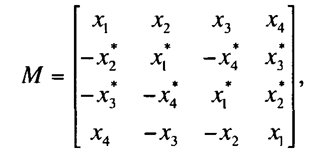
- the coding matrix M can be obtained by a Jafarkhani type coding, and is of the form: where x i is a reference symbol and x * / i is a conjugate reference symbol, with i a relative integer, 1 ⁇ i ⁇ 4.
- the invention also relates to a digital signal formed of n vectors emitted respectively using n transmitting antennas, n being strictly greater than 2.
- the signal comprises coded reference symbols, obtained after mathematical transformation of reference symbols by a unit efficiency coding matrix M , so as to enable, in a receiver, to estimate at least two transmission channels. respectively corresponding to each of the transmitting antennas.
- the invention also relates to a method for estimating at least one transmission channel in a multi-antenna system implementing n transmit antennas, where n is strictly greater than 2, and at least one receiving antenna.
- a vector of source data n vectors to be transmitted respectively by each of said transmission antennas is associated with an encoding matrix M , using reference symbols known from at least a receiver and allowing the latter to estimate at least two transmission channels respectively corresponding to each of the transmitting antennas.
- such an estimation method comprises a step of receiving a received reference vector, corresponding to an emitted reference vector obtained by the multiplication of reference symbols by said coding matrix M , and modified by least one transmission channel for each of the transmitting antennas.
- the received reference vector undergoes a mathematical transformation by a decoding matrix, inverse to the coding matrix and taking into account the effect of a transmission channel associated with the receiving antenna, for provide an estimate of the effects of the transmission channels on the reference symbols.
- the invention is based on an entirely new and inventive approach channel estimation in a multi-antenna system with more than two antennas resignation. Note that this approach is also new in a system to two transmitting antennas.
- the estimation of the different transmission channels is carried out on the basis of known reference symbols of at least one receiver, a reference symbol vector being associated with the coding matrix M via a encoding function.
- the different transmission channels can be estimated, from the inverse of the coding matrix, corresponding to the decoding matrix.
- a reception device may implement decoding, filtering or equalizing, and recombination of the signals from the various antennas, in order to estimate the different transmission channels.
- the decoding matrix is an inverse matrix integrating an equalization in the sense of the MMSE criterion (in English “Minimum Mean Squared Error “for” minimizing the mean squared error ”) or ZF (in English) "Zero Forcing” for "zero forcing”).
- the criterion used may be the MMSE criterion.
- the estimation method comprises a step interpolation, delivering an estimation of the transmission channels for each useful data, from the estimation of the reference symbols.
- the interpolation stage is remarkable in that it time interpolation and / or frequency interpolation.
- the general principle of the invention is based on the association of an encoding matrix M with a vector of reference symbols, known from at least one receiver, so as to enable the receiver to estimate the different channels. propagation between more than two transmitting antennas and a receiving antenna.
- This coding matrix M is either non-orthogonal or orthogonal in blocks and has a yield equal to 1, the efficiency being defined as the ratio between the number of transmitted symbols and the number of symbol times during which they are transmitted.
- the symbols of the coding matrix M are then distributed in time and / or in frequency on each of the transmitting antennas.
- the received signal is multiplied by the inverse matrix (integrating an equalization technique in the sense of the MMSE or ZF criterion) of the coding matrix M , possibly taking into account the noise introduced by the receiver.
- n- dimensional vector which represents the n transmission channels between the n transmit antennas and this receive antenna.
- This n- dimensional vector is then used by the receiver to estimate the transmission channel, in particular by repeating this operation periodically and by performing a temporal and / or frequency interpolation between two reference symbols estimated during this operation.
- the interpolation is for example of linear type or Wiener.
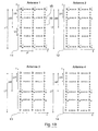
- FIGS. 1A and 1B a first embodiment of embodiment of the invention, in which an attempt is made to estimate the transmission of a multi-antenna system to 4 transmit antennas.
- the coding matrix M is a block matrix, each of the blocks comprising n reference symbols.
- An orthogonal space-time Alamouti coding is then applied to each block of the coding matrix M.
- Each of the blocks of n reference symbols is then orthogonal.
- the Alamouti coding on the reference symbols used to estimate the channel then these coded reference symbols are transmitted on a pair of antennas while keeping the other pair of antennas off.
- the coding matrix M associated with it via the coding function is: where x i is a reference symbol, x * / i is a conjugate reference symbol, with i a relative integer and 1 ⁇ i ⁇ 4, and 0 means that no symbol is transmitted on the relevant antenna.
- the reference symbols of the coding matrix M are then transmitted after space-frequency distribution (FIG. 1A) or space-time (FIG. 1B) on the different transmission antennas, the spatial axis representing the columns of the matrix M and the frequency axis (FIG. 1A) or time axis (FIG. 1B) representing the rows of the matrix M.
- space-time or space-frequency distributions symbols may be envisaged, as well as a combination of space-time and space-frequency distributions.
- each block of the coding matrix M is transmitted independently on its respective antennas, while the other blocks of the coding matrix are not transmitted.
- each block of reference symbols is transmitted separately, each of the blocks being transmitted on certain transmitting antennas while the other antennas are off.
- FIG. 1A the symbols emitted by the 4 antennas 11, 12, 13, 14 of a multi-antenna system with 4 transmitting antennas are presented, the transmitted symbols being distributed in the frequency domain (ordinate axis), with X i a referenced reference symbol 15, X i * a conjugated reference symbol ( i a relative integer and 1 ⁇ i ⁇ 4), x a data symbol, referenced 16, and 0 means that no symbol is emitted .
- the symbols emitted by the 4 antennas 11, 12, 13, 14 are distributed in the space-frequency domain (FIG. 1A) or space-time (FIG. 1B) as a function of the parameters ⁇ F, ⁇ f 1 , ⁇ f 2 (FIG. 1A), ⁇ T, ⁇ t 1 , ⁇ t 2 (FIG. 1B), representing the repeating patterns of the reference symbols.
- ⁇ f ⁇ F, ⁇ f 1 , ⁇ f 2 ⁇
- ⁇ t ⁇ T, ⁇ t 1 , ⁇ t 2 ⁇
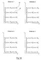
- FIGS. 2A and 2B also show another example of the space-time distribution (FIG. 2A) or space-frequency (FIG. 2B) of the symbols according to this first embodiment, as a function of the parameters ⁇ F, ⁇ f 1 , ⁇ f 2 ( Figure 2A), ⁇ T, ⁇ t 1 , ⁇ t 2 ( Figure 2B).
- each of the reception antennas it is sought to estimate the transmission channel h by applying to the reference vector received a mathematical transformation by a decoding matrix, corresponding to the inverse matrix integrating an equalization technique in the sense of the MMSE or ZF criterion. of the coding matrix M.
- the receiver can determine the coefficients of the propagation channel to the carriers k, k + 1, k + 2, ..., k + ⁇ f 1 -1, k + ⁇ f 1 .
- An interpolation can also be performed in the time domain, considering that the reference symbols are issued at time p on the carrier k, at the moment p + ⁇ t on the same carrier k, ....
- the receiver can then determine the coefficients of the propagation channel at times p, p + 1, p + 2, ..., p + ⁇ t-1, p + ⁇ t and so on.
- the receiver can therefore perform temporal interpolation and / or frequency interpolation.
- This interpolation step implements a interpolation technique well known to those skilled in the art, such as example linear interpolation, or Wiener.
- Each pair of antennas then emits alternately the symbols of distributed on its antennas, so as to estimate all the channels of transmission of the mutli-antennas system.
- orthogonal space-time codes it is thus possible to apply orthogonal space-time codes to systems having a larger number of transmitting antennas, with the aid of an M coding matrix retaining a yield equal to 1.
- Alamouti coding with a yield equal to 1, to systems with 4, 6, 8, ..., transmit antennas (whereas according to the state of the art, the number of antennas d transmission of the transmission system is limited by the use of orthogonal space-time codes).
- this channel estimation technique has better performance in terms of estimation since the others are extinguished groups of antennas when a group of antennas emits, this technique accompanied by a loss in spectral efficiency and does not allow to take advantage of the total power of the antennas, some carriers not carrying any information to defined moments.
- a second embodiment of the invention is then presented, in which the reference symbols are transmitted on all the transmit antennas after mathematical transformation by the coding matrix M , the coding matrix M being non-orthogonal.
- a space-time coding is applied non-orthogonal, Jafarkhani type, as presented in "A Quasi-Orthogonal Space-Time Block Code "(IEEE Transactions on Communications, Vol 49, No. 1, 2001, pp.1-4), on the reference symbols used to estimate the channel.
- This coding makes it possible in particular to emit signals presenting a weak interference.
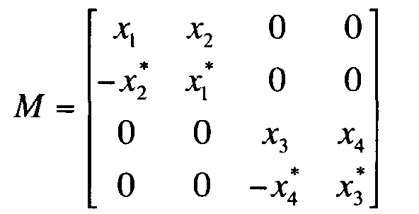
- the coding matrix M associated with it via the coding function is: where x i is a reference symbol, x * / i is a conjugate reference symbol, with i a relative integer, 1 ⁇ i ⁇ 4.
- All the reference symbols of the coding matrix M are then transmitted after space / frequency distribution on all the transmitting antennas, the spatial axis representing the columns of the matrix M and the frequency or time axis representing the lines of the matrix M.
- This matrix is of full rank, so that it can be inverted during the estimation of the different channels.
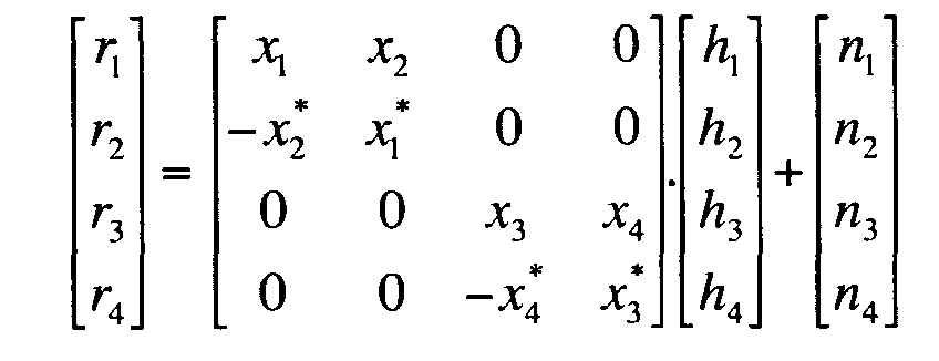
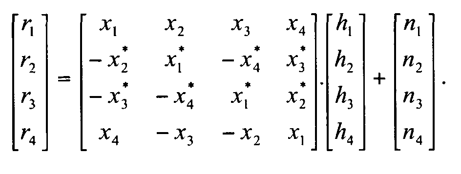
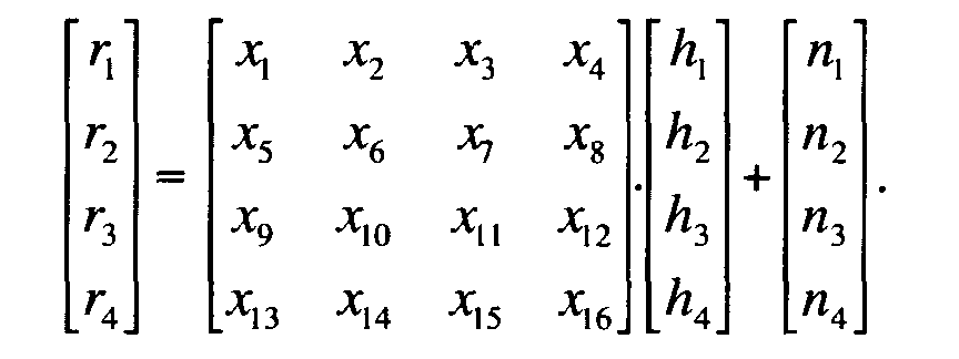
- the reference symbols of the coding matrix M are transmitted after space / frequency distribution on all the transmitting antennas, and the reference vector received at a reception antenna, modified by the channel of transmission, can be written in the form
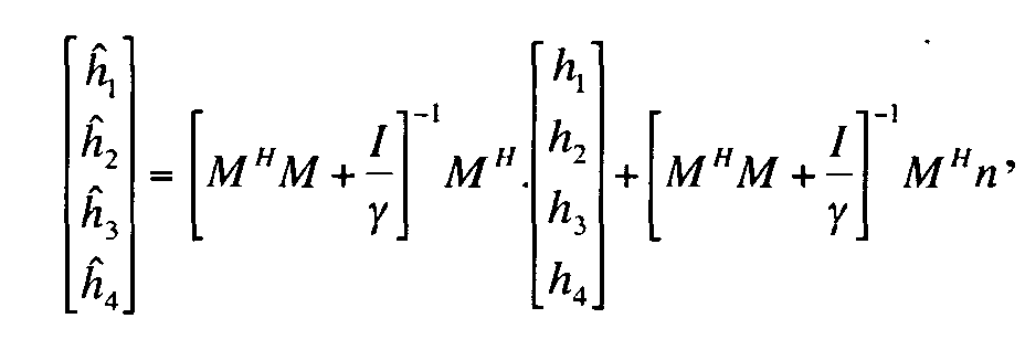
- a mathematical transformation is applied to the reference vector received by a decoding matrix, corresponding to the inverse matrix integrating an equalization technique in the sense of the MMSE or ZF criterion of the coding matrix M , to estimate the transmission channel h .
- the coefficients can then be determined missing from a transmission channel by applying temporal interpolation or frequency (or both) at the receiver, using a technique classic interpolation.
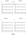
- FIGS. embodiments of the invention are now presented in relation to FIGS. embodiment of the invention, applying more particularly to multi-antenna systems of the MIMO type.
- a flexible principle is proposed allowing to apply either a spatio-temporal coding or a spatio-frequency coding, depending on the characteristics of the transmission channel.
- FIG. 3A illustrates the transmission of 4 reference symbols and their time-spaced conjugates, in a multi-antenna system with 4 transmit antennas, with X i a referenced reference symbol 15, X * / i a symbol conjugate reference ( i a relative integer and 1 ⁇ i ⁇ 4), x a data symbol, referenced 16.
- FIG. 3B illustrates the emission of 4 reference symbols and their conjugates frequently spaced in a 4-way multi-antenna system transmit antennas.
- the reference symbols once coded via the coding matrix M , are distributed along the time axis or the frequency axis according to the properties of the propagation channel.
- the temporal distribution is rather applied in the case of a temporally varying channel, while the distribution Frequency is further applied for a frequency varying channel.
- the different transmission antennas emit, on the same carrier and at the same time, a signal characterized by a coding space-time and / or space-frequency, which limits the loss in spectral efficiency.
- This signal therefore intrinsically includes the characteristics of the invention.
- a receiver can estimate each of the transmission channels between the different transmit and receive antennas from this coding specific and appropriate treatment described above.
- the technique particular channel estimation proposed according to the invention can also be applied to the case of a system having two transmitting antennas.
Landscapes
- Engineering & Computer Science (AREA)
- Computer Networks & Wireless Communication (AREA)
- Signal Processing (AREA)
- Power Engineering (AREA)
- Physics & Mathematics (AREA)
- Mathematical Physics (AREA)
- Radio Transmission System (AREA)
Abstract
Description
Le domaine de l'invention est celui des communications numériques par voie hertzienne. Plus précisément, l'invention concerne l'émission et la réception, et notamment l'estimation des canaux de transmission dans un système multi-antennes de type MIMO (« Multiple Input Multiple Output » pour « Entrées Multiples Sorties Multiples ») ou MISO (« Multiple Input Single Output » pour « Entrées Multiples Sortie Unique»), à partir de la transmission de signaux soumis à un codage espace-temps et/ou espace-fréquence.The field of the invention is that of digital communications by hertzian way. More specifically, the invention relates to transmission and reception, and in particular the estimation of the transmission channels in a multi-antenna system MIMO type ("Multiple Input Multiple Output" for "Inputs Multiple Multiple Outputs ") or MISO (" Multiple Input Single Output "for "Multiple Inputs Single Output"), from the submitted signal transmission to a space-time and / or space-frequency coding.
Plus précisément encore, l'invention s'applique aux systèmes multi-antennes mettant en oeuvre plusieurs, et notamment plus de deux antennes d'émission. Les signaux comprennent des symboles de référence, connus d'au moins un récepteur et permettant à ce dernier d'estimer les canaux de transmission correspondant à chacune des antennes d'émission.More specifically, the invention applies to multi-antenna systems implementing several, including more than two antennas resignation. The signals comprise reference symbols known from least one receiver and allowing the latter to estimate the transmission channels corresponding to each of the transmitting antennas.
Un exemple d'application de l'invention est le domaine des radiocommunications, notamment pour les systèmes de troisième, quatrième génération et suivantes.An example of application of the invention is the field of radiocommunications, in particular for third, fourth generation and following.
L'invention peut s'appliquer aux communications sur voie montante (d'un terminal vers une station de base), ainsi qu'aux communications sur voie descendante (d'une station de base vers un terminal).The invention can be applied to uplink communications (of a terminal to a base station), as well as to channel communications downward (from a base station to a terminal).
On connaít déjà plusieurs techniques d'estimation des canaux de transmission dans un système multi-antennes comprenant plusieurs antennes d'émission.We already know several techniques for estimating transmission in a multi-antenna system comprising several antennas resignation.
La plupart de ces techniques d'estimation se limite à l'application d'un codage espace-temps ou espace-fréquence dans des systèmes multiporteuses de type OFDM.Most of these estimation techniques are limited to the application of a space-time or space-frequency coding in multicarrier systems OFDM type.
Ainsi, les premiers systèmes proposés utilisaient tous des codes espace-temps en blocs orthogonaux. Thus, the first proposed systems all used space-time codes in orthogonal blocks.
Alamouti, dans "A Simple Transmit Diversity Technique for Wireless Communications", IEEE Journal on Selected Areas in Communications, pp. 311-335, vol. 6, 1998, a présenté le premier système utilisant un code espace-temps en blocs orthogonal à rendement de 1 (où le rendement est défini comme le rapport entre le nombre N de symboles émis et le nombre L de temps symboles pendant lequel ils sont émis), pour deux antennes d'émission.Alamouti, in "A Simple Transmit Diversity Technique for Wireless Communications, "IEEE Journal on Selected Areas in Communications, pp. 311-335, flight. 6, 1998, introduced the first system using a space-time code in orthogonal blocks with a yield of 1 (where the output is defined as the ratio between the number N of transmitted symbols and the number L of symbols during which they are issued), for two transmitting antennas.
Un inconvénient majeur des codes espace-temps orthogonaux d'Alamouti est qu'ils sont limités aux systèmes à deux antennes d'émission, et qu'il n'est pas possible de les généraliser directement à un système à plus de deux antennes d'émission, tout en conservant un rendement unitaire.A major disadvantage of orthogonal space-time codes of Alamouti is that they are limited to two-antenna transmitting systems, and that it is not possible to generalize them directly to a system with more than two antennas of issue, while maintaining a unit yield.
Tarokh et al. ("Space-time Block Codes from Orthogonal Designs", IEEE Transactions on Information Theory, 1999, 45, (5), pp. 1456-1467) ont ensuite généralisé les codes espace-temps en blocs orthogonaux aux systèmes comprenant trois ou quatre antennes d'émission. Cependant, les rendements R=N/L obtenus n'étaient que de 1/2 ou 3/4.Tarokh et al. ("Space-time Block Codes from Orthogonal Designs", IEEE Transactions on Information Theory, 1999, 45, (5), pp. 1456-1467) were then generalized space-time codes in orthogonal blocks to systems comprising three or four transmitting antennas. However, the yields R = N / L obtained were only 1/2 or 3/4.
Un inconvénient des codes espace-temps orthogonaux de Tarokh est donc que, bien qu'ils soient adaptés à des systèmes mettant en oeuvre un nombre supérieur d'antennes d'émission (trois ou quatre antennes), ils présentent un rendement inférieur à 1.A disadvantage of orthogonal space-time codes of Tarokh is therefore that, although they are suitable for systems implementing a number of transmit antennas (three or four antennas), they have a yield less than 1.
Barhumi et al. ont ensuite proposé dans "Pilot Tone-based Channel estimation for OFDM Systemes with Transmitter Diversity in Mobile Wireless Channels" une technique d'estimation de canal pour des systèmes OFDM multi-antennes (SISO-OFDM ou MIMO-OFDM), reposant sur une méthode d'estimation de canal OFDM classique, mettant notamment en oeuvre une extinction de certaines porteuses. Cependant, un inconvénient de cette technique d'estimation dans un système MIMO est que l'insertion de symboles de référence engendre en général une perte importante en efficacité spectrale, dès lors que pour chaque antenne d'émission, un symbole de référence est émis sur une porteuse de référence à un instant donné tandis que sur 1'(es) autre(s) porteuses, aucune donnée n'est émise afin de ne pas venir perturber l'estimation du canal de transmission.Barhumi et al. then proposed in "Pilot Tone-based Channel estimation for OFDM Systems with Transmitter Diversity in Mobile Wireless Channels "a channel estimation technique for multi-antenna OFDM systems (SISO-OFDM or MIMO-OFDM), based on a method conventional OFDM channel estimation, including implementing a extinction of certain carriers. However, a disadvantage of this technique of estimation in a MIMO system is that the insertion of reference symbols generates in general a significant loss in spectral efficiency, since for each transmitting antenna, a reference symbol is transmitted on a carrier of reference to a given moment while on the other carrier (s), no data is issued so as not to disturb the estimate of the transmission.
D'autres travaux ont ensuite été menés par Fragouli et al. dans "Training Based Channel Estimation for Multiple-Antenna Broadband Transmissions" concernant les séquences d'apprentissage pouvant être utilisées pour l'estimation de canal pour des systèmes multi-antennes.Other work was then conducted by Fragouli et al. in "Training Based Channel Estimation for Multiple-Antenna Broadband Transmissions " concerning learning sequences that can be used for estimation channel for multi-antenna systems.
Par la suite, Stirling-Gallacher et al.("Improving performance of coherent coded OFDM systems using space time transmit diversity", Electronics Letterers , vol. 37 N, Mars 2001, "Practical Pilot Patterns coherent coded OFDM systems using space time transmit diversity", European Wireless 2002 conference, 25-28 février 2002, Florence) ont envisagé une technique d'estimation de canal pour les systèmes MIMO-OFDM, se limitant à des systèmes à 2 antennes d'émission utilisant des codes espace/temps orthogonaux de type Alamouti ou Tarokh.Subsequently, Stirling-Gallacher et al. ("Improving performance of coherent coded OFDM systems using space time diversity ", Electronics Letterers, flight. 37 N, March 2001, Practical Pilot Patterns coherent coded OFDM systems using space time transmit diversity ", European Wireless 2002 conference, 25-28 February 2002, Florence) considered a channel estimation technique for MIMO-OFDM systems, limited to systems with 2 transmit antennas using orthogonal space-time codes of the Alamouti or Tarokh type.
Un inconvénient de cette technique d'estimation est que le nombre d'antennes d'émission du système de transmission est limité par l'utilisation de codes espace-temps en blocs orthogonaux connus.A disadvantage of this estimation technique is that the number transmitting antennas of the transmission system is limited by the use of space-time codes in known orthogonal blocks.
Ainsi, selon les techniques de l'art antérieur, il n'existe pas de codes orthogonaux complexes à rendement unitaire pour les systèmes à plus de deux antennes d'émission, ce qui diminue l'efficacité spectrale.Thus, according to the techniques of the prior art, there are no codes Complex Orthogonal Yields for Systems with More Than Two transmit antennas, which decreases spectral efficiency.
L'invention a notamment pour objectif de pallier ces inconvénients de l'art antérieur.The object of the invention is in particular to overcome these drawbacks of the art prior.
Plus précisément, un objectif de l'invention est de fournir une technique d'estimation d'au moins un canal de transmission dans un système multi-antennes mettant en oeuvre plus de deux antennes d'émission.More specifically, an object of the invention is to provide a technique estimating at least one transmission channel in a multi-antenna system implementing more than two transmitting antennas.
Un autre objectif de l'invention est de proposer une telle technique qui soit plus efficace et performante que les techniques connues, tout en présentant une complexité réduite.Another object of the invention is to propose such a technique which is more efficient and effective than the known techniques, while presenting a reduced complexity.
Encore un autre objectif de l'invention est de fournir une technique d'émission d'un signal comprenant des symboles de référence mettant en oeuvre une matrice de codage espace-temps et/ou espace-fréquence. Notamment, un objectif de l'invention est de fournir une matrice de codage de rendement unitaire.Yet another object of the invention is to provide a technique for transmitting a signal comprising reference symbols implementing a space-time and / or space-frequency coding matrix. In particular, a The object of the invention is to provide a unit efficiency coding matrix.
L'invention a encore pour objectif de fournir une telle technique qui soit adaptée aux systèmes multi-antennes de type MISO ou MIMO pour des modulations de type monoporteuse ou multiporteuses, combinées aux différentes techniques d'accès multiple (CDMA, de l'anglais « Code Division Multiplex Access » pour « accès multiple à répartition par code », FDMA pour « accès multiple fréquentiel », ou TDMA pour « accès multiple temporel »).It is another object of the invention to provide such a technique which is suitable for multi-antenna systems of the MISO or MIMO type for single-carrier or multicarrier modulations, combined with the various multiple access ( CDMA) techniques. Code Division Multiplex Access "for" code division multiple access ", FDMA for" frequency multiple access ", or TDMA for" multiple time access ").
Un autre objectif de l'invention est de proposer une telle technique qui permette d'augmenter la diversité spatiale des systèmes tout en minimisant l'interférence entre les différents canaux de transmission et en limitant la perte d'efficacité spectrale.Another object of the invention is to propose such a technique which to increase the spatial diversity of systems while minimizing interference between different transmission channels and limiting the loss spectral efficiency.
En d'autres termes, l'invention a pour objectif de fournir une telle technique, qui puisse être mise en oeuvre de façon pratique et peu coûteuse dans un système mettant en oeuvre un nombre élevé d'antennes.In other words, the object of the invention is to provide such which can be implemented in a practical and inexpensive way in a system implementing a high number of antennas.
Ces objectifs, ainsi que d'autres qui apparaítront par la suite, sont atteints à l'aide d'un procédé d'émission d'un signal numérique à l'aide de n antennes d'émission, n étant strictement supérieur à 2, selon lequel on associe, à un vecteur de données source, n vecteurs à émettre respectivement par chacune desdites antennes d'émission, à l'aide d'une matrice de codage M de rendement égal à 1, mettant en oeuvre des symboles de référence, connus d'au moins un récepteur et permettant à ce dernier d'estimer au moins deux canaux de transmission correspondant respectivement à chacune desdites antennes d'émission.These objectives, as well as others which will appear later, are achieved by means of a method of transmitting a digital signal using n transmitting antennas, n being strictly greater than 2, according to which a vector of source data is associated with n vectors to be transmitted respectively by each of said transmission antennas, using a coding matrix M of output equal to 1, implementing reference symbols, at least one receiver and allowing the latter to estimate at least two transmission channels respectively corresponding to each of said transmitting antennas.
Selon l'invention, lesdits symboles de référence d'un tel procédé d'émission subissent une transformation mathématique par ladite matrice de codage M avant leur émission.According to the invention, said reference symbols of such an emission method undergo a mathematical transformation by said coding matrix M before their transmission.
Ainsi, l'invention repose sur une approche tout à fait nouvelle et inventive de l'émission d'un signal numérique, mettant en oeuvre une matrice de codage dans un système multi-antennes à plus de deux antennes d'émission. Thus, the invention is based on an entirely new and inventive approach of the transmission of a digital signal, implementing a coding matrix in a multi-antenna system with more than two transmit antennas.
Plus précisément, l'invention propose d'émettre sur les n antennes d'émission les symboles de référence de la matrice de codage M de rendement égal à 1, un vecteur de symboles de référence étant associé à la matrice de codage M par l'intermédiaire d'une fonction de codage.More precisely, the invention proposes transmitting on the n transmit antennas the reference symbols of the coding matrix M of output equal to 1, a reference symbol vector being associated with the coding matrix M by the intermediate of a coding function.
Une telle matrice de codage M de rendement égal à 1 correspond soit à une matrice non orthogonale, soit à une matrice orthogonale par blocs, le rendement étant défini comme le rapport entre le nombre de symboles émis et le nombre de temps symboles pendant lequel ils sont émis.Such a coding matrix M with a yield of 1 corresponds either to a non-orthogonal matrix or to an orthogonal matrix in blocks, the efficiency being defined as the ratio between the number of transmitted symbols and the number of symbol times during which they are issued.
Avantageusement, les symboles de référence sont répartis en espace et en temps et/ou en espace et en fréquence.Advantageously, the reference symbols are distributed in space and in time and / or space and frequency.
La matrice de codage met alors en oeuvre un codage espace-temps et/ou espace-fréquence.The coding matrix then implements a space-time coding and / or space-frequency.
Selon un premier mode de réalisation, la matrice de codage comprend au moins deux blocs, chacun des blocs étant orthogonaux.According to a first embodiment, the coding matrix comprises at least minus two blocks, each block being orthogonal.
De manière préférentielle, chacun des blocs de symboles de référence est émis séparément, chacun des blocs étant émis sur certaines antennes d'émission, les autres antennes d'émission étant éteintes.Preferably, each of the reference symbol blocks is issued separately, each block being transmitted on certain transmitting antennas, the other transmitting antennas are off.
Ainsi les données émises par un premier ensemble d'antennes ne sont pas perturbées par les données émises par un autre ensemble d'antennes, l'autre ensemble d'antennes n'émettant pas sur les mêmes porteuses au même instant.Thus the data transmitted by a first set of antennas are not disturbed by data transmitted by another set of antennas, the other set of antennas not emitting on the same carriers at the same time.
Selon un autre mode de réalisation de l'invention, dit troisième mode de réalisation, le procédé d'émission comprend une étape de sélection entre une répartition en fréquence et une répartition en temps.According to another embodiment of the invention, said third mode of realization, the transmission method comprises a selection step between a frequency distribution and time distribution.
Notamment, cette étape de sélection peut tenir compte des caractéristiques d'un canal de transmission.In particular, this selection step may take into account the characteristics a transmission channel.
Selon un autre mode de réalisation de l'invention, dit second mode de réalisation, les symboles de référence sont émis sur l'ensemble des antennes d'émission après transformation mathématique par la matrice de codage M.According to another embodiment of the invention, said second embodiment, the reference symbols are transmitted on all the transmit antennas after mathematical transformation by the coding matrix M.
Ainsi la matrice de codage M est une matrice globalement non orthogonale. Thus the coding matrix M is a globally non-orthogonal matrix.
Notamment, la matrice de codage M peut être obtenue par un codage de
type Jafarkhani, et est de la forme :
L'invention concerne également un signal numérique formé de n vecteurs émis respectivement à l'aide de n antennes d'émission, n étant strictement supérieur à 2.The invention also relates to a digital signal formed of n vectors emitted respectively using n transmitting antennas, n being strictly greater than 2.
Selon l'invention, le signal comprend des symboles de référence codés, obtenus après transformation mathématique de symboles de référence par une matrice de codage M de rendement unitaire, de façon à permettre, dans un récepteur, d'estimer au moins deux canaux de transmission correspondant respectivement à chacune des antennes d'émission.According to the invention, the signal comprises coded reference symbols, obtained after mathematical transformation of reference symbols by a unit efficiency coding matrix M , so as to enable, in a receiver, to estimate at least two transmission channels. respectively corresponding to each of the transmitting antennas.
L'invention concerne encore un procédé d'estimation d'au moins un canal de transmission dans un système multi-antennes mettant en oeuvre n antennes d'émission, où n est strictement supérieur à 2, et au moins une antenne de réception. Selon ce procédé, on associe à un vecteur de données source n vecteurs à émettre respectivement par chacune desdites antennes d'émission, à l'aide d'une matrice de codage M, mettant en oeuvre des symboles de référence, connus d'au moins un récepteur et permettant à ce dernier d'estimer au moins deux canaux de transmission correspondant respectivement à chacune des antennes d'émission.The invention also relates to a method for estimating at least one transmission channel in a multi-antenna system implementing n transmit antennas, where n is strictly greater than 2, and at least one receiving antenna. According to this method, a vector of source data n vectors to be transmitted respectively by each of said transmission antennas is associated with an encoding matrix M , using reference symbols known from at least a receiver and allowing the latter to estimate at least two transmission channels respectively corresponding to each of the transmitting antennas.
Selon l'invention, un tel procédé d'estimation comprend une étape de réception d'un vecteur de référence reçu, correspondant à un vecteur de référence émis obtenu par la multiplication de symboles de référence par ladite matrice de codage M, et modifié par au moins un canal de transmission pour chacune des antennes d'émission. Pour chacune desdites antennes de réception, le vecteur de référence reçu subi une transformation mathématique par une matrice de décodage, inverse de la matrice de codage et tenant compte de l'effet d'un canal de transmission associé à l'antenne de réception, pour fournir une estimation des effets des canaux de transmission sur les symboles de référence.According to the invention, such an estimation method comprises a step of receiving a received reference vector, corresponding to an emitted reference vector obtained by the multiplication of reference symbols by said coding matrix M , and modified by least one transmission channel for each of the transmitting antennas. For each of said receiving antennas, the received reference vector undergoes a mathematical transformation by a decoding matrix, inverse to the coding matrix and taking into account the effect of a transmission channel associated with the receiving antenna, for provide an estimate of the effects of the transmission channels on the reference symbols.
Ainsi, l'invention repose sur une approche tout à fait nouvelle et inventive de l'estimation de canaux dans un système multi-antennes à plus de deux antennes d'émission. On notera que cette approche est également nouvelle dans un système à deux antennes d'émission.Thus, the invention is based on an entirely new and inventive approach channel estimation in a multi-antenna system with more than two antennas resignation. Note that this approach is also new in a system to two transmitting antennas.
En effet, l'estimation des différents canaux de transmission est mise en oeuvre à partir de symboles de référence connus d'au moins un récepteur, un vecteur de symboles de référence étant associé à la matrice de codage M par l'intermédiaire d'une fonction de codage.Indeed, the estimation of the different transmission channels is carried out on the basis of known reference symbols of at least one receiver, a reference symbol vector being associated with the coding matrix M via a encoding function.
Connaissant le vecteur de symboles de référence et la matrice de codage M utilisées, on peut estimer les différents canaux de transmission, à partir de l'inverse de la matrice de codage, correspondant à la matrice de décodage.Knowing the reference symbol vector and the coding matrix M used, the different transmission channels can be estimated, from the inverse of the coding matrix, corresponding to the decoding matrix.
Ainsi, à partir des symboles de référence et de la technique de codage utilisée, un dispositif de réception peut mettre en oeuvre des techniques de décodage, de filtrage ou d'égalisation, et une recombinaison des signaux issus des diverses antennes, afin d'estimer les différents canaux de transmission.Thus, from the reference symbols and coding technique used, a reception device may implement decoding, filtering or equalizing, and recombination of the signals from the various antennas, in order to estimate the different transmission channels.
Avantageusement, la matrice de décodage est une matrice inverse intégrant une égalisation au sens du critère MMSE (en anglais « Minimum Mean Squared Error » pour « minimisation de l'erreur quadratique moyenne ») ou ZF (en anglais « Zero Forcing » pour « forçage à zéro »).Advantageously, the decoding matrix is an inverse matrix integrating an equalization in the sense of the MMSE criterion (in English "Minimum Mean Squared Error "for" minimizing the mean squared error ") or ZF (in English) "Zero Forcing" for "zero forcing").
Notamment, le critère mis en oeuvre peut être le critère MMSE. La matrice
de décodage est alors formée des éléments :
Le critère mis en oeuvre peut également être le critère ZF. La matrice de
décodage est alors formée des éléments :
- r le vecteur de référence reçu ;
- M la matrice de codage ;
- I la matrice unité ;
- γ le rapport signal à bruit ;
- H le transposé conjugué.
- r the received reference vector;
- M the coding matrix;
- I the unit matrix;
- γ the signal-to-noise ratio;
- H the conjugated transpose.
De manière préférentielle, le procédé d'estimation comprend une étape d'interpolation, délivrant une estimation des canaux de transmission pour chacune des données utiles, à partir de l'estimation des symboles de référence.Preferably, the estimation method comprises a step interpolation, delivering an estimation of the transmission channels for each useful data, from the estimation of the reference symbols.
Notamment, l'étape d'interpolation est remarquable en ce qu'elle met en oeuvre une interpolation temporelle et/ou une interpolation fréquentielle.In particular, the interpolation stage is remarkable in that it time interpolation and / or frequency interpolation.
Cette étape d'interpolation peut appartenir au groupe comprenant :
- les interpolations linéaires ;
- les interpolations de Wiener.
- linear interpolations;
- the interpolations of Wiener.
D'autres caractéristiques et avantages de l'invention apparaítront plus clairement à la lecture de la description suivante d'un mode de réalisation préférentiel, donné à titre de simple exemple illustratif et non limitatif, et des dessins annexés, parmi lesquels :
- les figures 1A et 1B présentent un système d'estimation de canaux dans un système multi-antennes à 4 antennes d'émission, avec des symboles répartis dans le domaine fréquentiel (figure 1A) ou temporel (figure 1B) selon un premier mode de réalisation de l'invention ;
- les figures 2A et 2B présentent une répartition particulière des symboles du système d'estimation de canaux des figures 1A et 1B ;
- les figures 3A et 3B illustrent un système d'estimation de canaux dans un système multi-antennes à 4 antennes d'émission, avec des symboles répartis dans le domaine fréquentiel (figure 3A) ou temporel (figure 3B) selon un troisième mode de réalisation de l'invention.
- FIGS. 1A and 1B show a channel estimation system in a multi-antenna system with 4 transmission antennas, with symbols distributed in the frequency domain (FIG. 1A) or time domain (FIG. 1B) according to a first embodiment of the invention;
- FIGS. 2A and 2B show a particular distribution of the symbols of the channel estimation system of FIGS. 1A and 1B;
- FIGS. 3A and 3B illustrate a system for estimating channels in a multi-antenna system with 4 transmission antennas, with symbols distributed in the frequency domain (FIG. 3A) or time domain (FIG. 3B) according to a third embodiment of the invention.
Le principe général de l'invention repose sur l'association d'une matrice de codage M à un vecteur de symboles de référence, connus d'au moins un récepteur, de façon à permettre, dans le récepteur, d'estimer les différents canaux de propagation entre plus de deux antennes d'émission et une antenne de réception.The general principle of the invention is based on the association of an encoding matrix M with a vector of reference symbols, known from at least one receiver, so as to enable the receiver to estimate the different channels. propagation between more than two transmitting antennas and a receiving antenna.
Cette matrice de codage M est soit non orthogonale, soit orthogonale par blocs et présente un rendement égal à 1, le rendement étant défini comme le rapport entre le nombre de symboles émis et le nombre de temps symboles pendant lequel ils sont émis. Les symboles de la matrice de codage M sont ensuite répartis en temps et/ou en fréquence sur chacune des antennes d'émission.This coding matrix M is either non-orthogonal or orthogonal in blocks and has a yield equal to 1, the efficiency being defined as the ratio between the number of transmitted symbols and the number of symbol times during which they are transmitted. The symbols of the coding matrix M are then distributed in time and / or in frequency on each of the transmitting antennas.
A la réception, pour chaque antenne de réception, le signal reçu est multiplié par la matrice inverse (intégrant une technique d'égalisation au sens du critère MMSE ou ZF) de la matrice de codage M, en tenant compte éventuellement du bruit introduit par le récepteur.At the reception, for each receiving antenna, the received signal is multiplied by the inverse matrix (integrating an equalization technique in the sense of the MMSE or ZF criterion) of the coding matrix M , possibly taking into account the noise introduced by the receiver.
Le résultat est un vecteur à n dimensions qui représente les n canaux de transmission entre les n antennes d'émission et cette antenne de réception. Ce vecteur à n dimensions est ensuite utilisé par le récepteur pour estimer le canal de transmission, notamment en répétant cette opération périodiquement et en réalisant une interpolation temporelle et/ou fréquentielle entre deux symboles de référence estimés lors de cette opération. L'interpolation est par exemple de type linéaire ou de Wiener.The result is an n- dimensional vector which represents the n transmission channels between the n transmit antennas and this receive antenna. This n- dimensional vector is then used by the receiver to estimate the transmission channel, in particular by repeating this operation periodically and by performing a temporal and / or frequency interpolation between two reference symbols estimated during this operation. The interpolation is for example of linear type or Wiener.
On présente, en relation avec les figures 1A et 1B, un premier mode de réalisation de l'invention, dans lequel on cherche à estimer les canaux de transmission d'un système multi-antennes à 4 antennes d'émission.With reference to FIGS. 1A and 1B, a first embodiment of embodiment of the invention, in which an attempt is made to estimate the transmission of a multi-antenna system to 4 transmit antennas.
Selon ce premier mode de réalisation, la matrice de codage M est une matrice par blocs, chacun des blocs comprenant n symboles de référence. On applique alors un codage d'Alamouti espace-temps orthogonal sur chaque bloc de la matrice de codage M. Chacun des blocs de n symboles de référence est alors orthogonal. According to this first embodiment, the coding matrix M is a block matrix, each of the blocks comprising n reference symbols. An orthogonal space-time Alamouti coding is then applied to each block of the coding matrix M. Each of the blocks of n reference symbols is then orthogonal.
L'Homme du Métier étendra facilement cet enseignement au cas où le nombre d'antennes, en émission et/ou en réception, est plus élevé. On peut ainsi appliquer un codage d'Alamouti sur chacun des blocs d'un système à n = 4, 6, 8,... antennes d'émission.The skilled person will easily extend this teaching in case the number of antennas, transmission and / or reception, is higher. It is thus possible to apply an Alamouti coding on each of the blocks of a system with n = 4, 6, 8, ... transmit antennas.
Selon ce mode de réalisation illustré en figures 1A et 1B, on applique le codage d'Alamouti sur les symboles de référence servant à l'estimation du canal, puis on émet ces symboles de référence codés sur un couple d'antennes d'émission, tout en gardant l'autre couple d'antennes éteint.According to this embodiment illustrated in FIGS. 1A and 1B, the Alamouti coding on the reference symbols used to estimate the channel, then these coded reference symbols are transmitted on a pair of antennas while keeping the other pair of antennas off.
Ainsi, si on considère le vecteur de symboles de référence
[x 1 x 2 x 3 x4], la matrice de codage M qui lui est associé par l'intermédiaire de
la fonction de codage est :
Chaque bloc
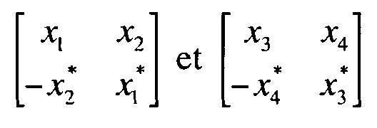
Les symboles de référence de la matrice de codage M sont ensuite émis après répartition espace-fréquence (figure 1A) ou espace-temps (figure 1B) sur les différentes antennes d'émission, l'axe spatial représentant les colonnes de la matrice M et l'axe fréquentiel (figure 1A) ou temporel (figure 1B) représentant les lignes de la matrice M.The reference symbols of the coding matrix M are then transmitted after space-frequency distribution (FIG. 1A) or space-time (FIG. 1B) on the different transmission antennas, the spatial axis representing the columns of the matrix M and the frequency axis (FIG. 1A) or time axis (FIG. 1B) representing the rows of the matrix M.
Il est bien entendu que d'autres répartitions espace-temps ou espace-fréquence des symboles peuvent être envisagées, ainsi qu'une combinaison des répartitions espace-temps et espace-fréquence. It is understood that other space-time or space-frequency distributions symbols may be envisaged, as well as a combination of space-time and space-frequency distributions.
En fait, chaque bloc de la matrice de codage M est émis indépendamment sur ses antennes respectives, pendant que les autres blocs de la matrice de codage ne sont pas émis. Autrement dit, chaque bloc de symboles de référence est émis séparément, chacun des blocs étant émis sur certaines antennes d'émission tandis que les autres antennes sont éteintes.In fact, each block of the coding matrix M is transmitted independently on its respective antennas, while the other blocks of the coding matrix are not transmitted. In other words, each block of reference symbols is transmitted separately, each of the blocks being transmitted on certain transmitting antennas while the other antennas are off.
On présente ainsi en figure 1A les symboles émis par les 4 antennes 11,
12, 13, 14 d'un système multi-antennes à 4 antennes d'émission, les symboles
émis étant répartis dans le domaine fréquentiel (axe des ordonnées), avec X i un
symbole de référence référencé 15, X i * un symbole de référence conjugué (i un
entier relatif et 1 ≤ i ≤ 4), x un symbole de données, référencé 16, et 0 signifie
qu'aucun symbole n'est émis.Thus, in FIG. 1A, the symbols emitted by the 4
Les symboles émis par les 4 antennes 11, 12, 13, 14 sont répartis dans le
domaine espace-fréquence (figure 1A) ou espace-temps (figure 1B) en fonction
des paramètres ΔF, Δf1, Δf2 (figure 1A), ΔT, Δt1, Δt2 (figure 1B), représentant les
motifs de répétition des symboles de référence.The symbols emitted by the 4
Les valeurs choisies pour Δf, correspondant à l'espacement entre deux porteuses de référence (dans cet exemple Δf = {ΔF, Δf1, Δf2}), et pour Δt, correspondant à l'espacement entre deux symboles de référence à des instants connus (dans cet exemple Δt = {ΔT, Δt1, Δt2}), ne sont pas propres au système proposé mais dépendent de la stationnarité du canal de transmission.The values chosen for Δf, corresponding to the spacing between two reference carriers (in this example Δf = {ΔF, Δf 1 , Δf 2 }), and for Δt, corresponding to the spacing between two reference symbols at times known (in this example Δt = {ΔT, Δt 1 , Δt 2 }), are not specific to the proposed system but depend on the stationarity of the transmission channel.
En général, on considère :
- ΔF << Bc, avec Bc la bande de cohérence du canal ;
- ΔT << Tc, avec Tc le temps de cohérence du canal ;
- Δf1 vérifie au mieux la stationnarité fréquentielle du canal ;
- Δt1 vérifie au mieux la stationnarité temporelle du canal ;
- Δf2 et Δt2 dépendent d'un compromis entre la perte en efficacité spectrale et les performances du système.
- ΔF << B c , with B c the coherence band of the channel;
- ΔT << T c , with T c the coherence time of the channel;
- Δf 1 optimally checks the frequency stationarity of the channel;
- Δt 1 optimally checks the temporal stationarity of the channel;
- Δf 2 and Δt 2 depend on a compromise between the loss in spectral efficiency and the performance of the system.
On présente également en figures 2A et 2B un autre exemple de la répartition espace-temps (figure 2A) ou espace-fréquence (figure 2B) des symboles selon ce premier mode de réalisation, en fonction des paramètres ΔF, Δf1, Δf2 (figure 2A), ΔT, Δt1, Δt2 (figure 2B).FIGS. 2A and 2B also show another example of the space-time distribution (FIG. 2A) or space-frequency (FIG. 2B) of the symbols according to this first embodiment, as a function of the parameters ΔF, Δf 1 , Δf 2 ( Figure 2A), ΔT, Δt 1 , Δt 2 (Figure 2B).
Selon cet exemple, la valeur des symboles de référence est choisie de sorte que X 1 = X 3 et X 2 = X 4.According to this example, the value of the reference symbols is chosen so that X 1 = X 3 and X 2 = X 4 .
Le vecteur de référence reçu au niveau d'une antenne de réception, modifié par le canal de transmission, peut alors s'écrire sous la forme r = Xh + n, où h correspond à une modélisation du canal de transmission et n est un vecteur de bruit blanc gaussien.The reference vector received at a receiving antenna, modified by the transmission channel, can then be written in the form r = Xh + n , where h corresponds to a modeling of the transmission channel and n is a vector white Gaussian noise.
On peut également écrire ce vecteur de référence reçu sous forme
vectorielle :
Pour chacune des antennes de réception, on cherche à estimer le canal de transmission h en appliquant au vecteur de référence reçu une transformation mathématique par une matrice de décodage, correspondant à la matrice inverse intégrant une technique d'égalisation au sens du critère MMSE ou ZF de la matrice de codage M.For each of the reception antennas, it is sought to estimate the transmission channel h by applying to the reference vector received a mathematical transformation by a decoding matrix, corresponding to the inverse matrix integrating an equalization technique in the sense of the MMSE or ZF criterion. of the coding matrix M.
Selon le critère MMSE, la matrice de décodage est formée des éléments :
- r ledit vecteur de référence reçu ;
- M ladite matrice de codage ;
- I une matrice unité ;
- γ le rapport signal à bruit ;
- H le transposé conjugué.
- r said reference vector received;
- M said coding matrix;
- I a unit matrix;
- γ the signal-to-noise ratio;
- H the conjugated transpose.
Selon le critère ZF, la matrice de décodage est formée des éléments :
- r ledit vecteur de référence reçu ;
- M ladite matrice de codage ;
- H le transposé conjugué.
- r said reference vector received;
- M said coding matrix;
- H the conjugated transpose.
Ces deux critères conduisent à des résultats identiques à fort rapport signal à bruit.These two criteria lead to identical results with a high signal ratio to noise.
Dans le cas d'un critère ZF, on obtient :

On peut ainsi déterminer les coefficients du canal à un instant p sur une porteuse k, à un instant p sur une porteuse k+Δf1, ..., comme illustré en figure 2A.It is thus possible to determine the channel coefficients at a time p on a carrier k, at a time p on a carrier k + Δf 1 , ..., as illustrated in FIG. 2A.
En appliquant une interpolation fréquentielle entre les deux porteuses k et k+Δf1 portant les symboles de références, le récepteur peut déterminer les coefficients du canal de propagation aux porteuses k, k+1, k+2, ..., k+Δf1-1, k+Δf1.By applying a frequency interpolation between the two carriers k and k + Δf 1 carrying the reference symbols, the receiver can determine the coefficients of the propagation channel to the carriers k, k + 1, k + 2, ..., k + Δf 1 -1, k + Δf 1 .
Une interpolation peut également être réalisée dans le domaine temporel, en considérant que les symboles de référence sont émis à l'instant p sur la porteuse k, à l'instant p+Δt sur la même porteuse k, .... Le récepteur peut alors déterminer les coefficients du canal de propagation aux instants p, p+1, p+2, ..., p+Δt-1, p+Δt et ainsi de suite.An interpolation can also be performed in the time domain, considering that the reference symbols are issued at time p on the carrier k, at the moment p + Δt on the same carrier k, .... The receiver can then determine the coefficients of the propagation channel at times p, p + 1, p + 2, ..., p + Δt-1, p + Δt and so on.
Le récepteur peut donc réaliser une interpolation temporelle et/ou une interpolation fréquentielle. Cette étape d'interpolation met en oeuvre une technique d'interpolation bien connue de l'Homme du Métier, comme par exemple une interpolation de type linéaire, ou de Wiener. The receiver can therefore perform temporal interpolation and / or frequency interpolation. This interpolation step implements a interpolation technique well known to those skilled in the art, such as example linear interpolation, or Wiener.
L'autre couple d'antennes n'émettant pas sur les mêmes porteuses et aux mêmes instants, comme illustré en figures 1A,1B, 2A et 2B, le signal émis par le premier couple d'antennes n'est pas perturbé.The other pair of antennas not emitting on the same carriers and same time, as illustrated in FIGS. 1A, 1B, 2A and 2B, the signal emitted by the first pair of antennas is not disturbed.
Chaque couple d'antennes émet alors alternativement les symboles de référence répartis sur ses antennes, de sorte à estimer l'ensemble des canaux de transmission du système mutli-antennes.Each pair of antennas then emits alternately the symbols of distributed on its antennas, so as to estimate all the channels of transmission of the mutli-antennas system.
Selon l'invention, on peut ainsi appliquer des codes espace-temps orthogonaux à des systèmes présentant un plus grand nombre d'antennes d'émission, à l'aide d'une matrice de codage M conservant un rendement égal à 1. On peut ainsi appliquer un codage d'Alamouti, de rendement égal à 1, à des systèmes présentant 4, 6, 8, ..., antennes d'émission (alors que selon l'état de l'art, le nombre d'antennes d'émission du système de transmission est limité du fait de l'utilisation de codes espace-temps orthogonaux).According to the invention, it is thus possible to apply orthogonal space-time codes to systems having a larger number of transmitting antennas, with the aid of an M coding matrix retaining a yield equal to 1. thus apply Alamouti coding, with a yield equal to 1, to systems with 4, 6, 8, ..., transmit antennas (whereas according to the state of the art, the number of antennas d transmission of the transmission system is limited by the use of orthogonal space-time codes).
Cependant, bien que cette technique d'estimation de canal présente de meilleures performances en termes d'estimation puisqu'on éteint les autres groupes d'antennes lorsqu'un groupe d'antennes émet, cette technique s'accompagne d'une perte en efficacité spectrale et ne permet pas de profiter de la puissance totale des antennes, certaines porteuses ne portant aucune information à des instants définis.However, although this channel estimation technique has better performance in terms of estimation since the others are extinguished groups of antennas when a group of antennas emits, this technique accompanied by a loss in spectral efficiency and does not allow to take advantage of the total power of the antennas, some carriers not carrying any information to defined moments.
On présente alors un second mode de réalisation de l'invention, dans lequel les symboles de référence sont émis sur l'ensemble des antennes d'émission après transformation mathématique par la matrice de codage M, la matrice de codage M étant non orthogonale.A second embodiment of the invention is then presented, in which the reference symbols are transmitted on all the transmit antennas after mathematical transformation by the coding matrix M , the coding matrix M being non-orthogonal.
Selon ce second mode de réalisation, on applique un codage espace-temps non orthogonal, de type Jafarkhani, comme présenté dans « A Quasi-Orthogonal Space-Time Block Code » (IEEE Transactions on Communications, Vol. 49, N°1, 2001, pp.1-4), sur les symboles de référence servant à l'estimation du canal.According to this second embodiment, a space-time coding is applied non-orthogonal, Jafarkhani type, as presented in "A Quasi-Orthogonal Space-Time Block Code "(IEEE Transactions on Communications, Vol 49, No. 1, 2001, pp.1-4), on the reference symbols used to estimate the channel.
Ce codage permet notamment d'émettre des signaux présentant une faible interférence. This coding makes it possible in particular to emit signals presenting a weak interference.
Ainsi, si on considère le vecteur de symboles de référence
[x 1 x 2 x 3 x 4], la matrice de codage M qui lui est associé par l'intermédiaire de
la fonction de codage est :
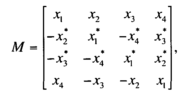
Tous les symboles de référence de la matrice de codage M sont ensuite émis après répartition espace/fréquence sur l'ensemble des antennes d'émission, l'axe spatial représentant les colonnes de la matrice M et l'axe fréquentiel ou temporel représentant les lignes de la matrice M.All the reference symbols of the coding matrix M are then transmitted after space / frequency distribution on all the transmitting antennas, the spatial axis representing the columns of the matrix M and the frequency or time axis representing the lines of the matrix M.
Comme décrit précédemment, le vecteur de référence reçu au niveau d'une antenne de réception, modifié par le canal de transmission, peut s'écrire sous la forme r = Xh + n, où h correspond à une modélisation du canal de transmission et n est un vecteur de bruit blanc gaussien.As described previously, the reference vector received at a receiving antenna, modified by the transmission channel, can be written in the form r = Xh + n, where h corresponds to a modeling of the transmission channel and n is a Gaussian white noise vector.
On peut également écrire ce vecteur de référence reçu sous forme
vectorielle :
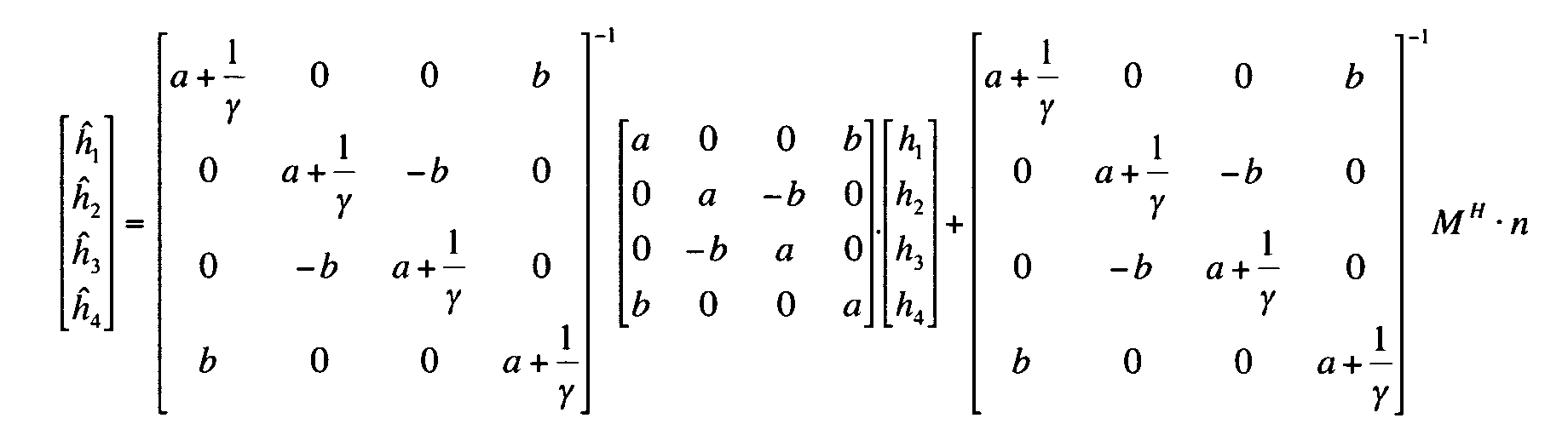
De nouveau, pour chacune des antennes de réception, on cherche à estimer le canal de transmission h en appliquant au vecteur de référence reçu une transformation mathématique par une matrice de décodage, correspondant à la matrice inverse intégrant une technique d'égalisation au sens du critère MMSE ou ZF de la matrice de codage M.Again, for each of the reception antennas, it is sought to estimate the transmission channel h by applying to the reference vector received a mathematical transformation by a decoding matrix corresponding to the inverse matrix integrating an equalization technique in the sense of the criterion MMSE or ZF of the coding matrix M.
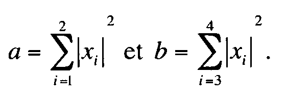
Dans le cas d'un critère MMSE, on obtient :

On réitère cette opération de manière identique pour chaque antenne de réception, quelque soit le nombre d'antennes. On peut ainsi déterminer les coefficients h c d'un canal de transmission à une fréquence c ou un instant c défini, et il ne reste qu'à appliquer une interpolation temporelle et/ou fréquentielle au niveau du récepteur entre les estimées de h c et h c+k (avec k = Δf dans le cas où c est une fréquence et k = Δt dans le cas où c est un instant) afin d'évaluer les valeurs manquantes. Ainsi, on obtient une connaissance globale de toutes les valeurs d'un canal de transmission pour chacune des antennes, ce qui permet d'égaliser le signal en réception de manière classique.This operation is repeated identically for each receiving antenna, regardless of the number of antennas. It is thus possible to determine the coefficients h c of a transmission channel at a frequency c or a defined instant c, and it remains only to apply a temporal and / or frequency interpolation at the receiver between the estimates of h c and h c + k (with k = Δf in the case where c is a frequency and k = Δt in the case where c is an instant) to evaluate the missing values. Thus, a global knowledge of all the values of a transmission channel for each of the antennas is obtained, which makes it possible to equalize the reception signal in a conventional manner.
Selon ce deuxième mode de réalisation, il est possible d'étendre cette technique d'estimation à des systèmes présentant un nombre supérieur à deux antennes d'émission.According to this second embodiment, it is possible to extend this estimation technique to systems with a number greater than two transmit antennas.
Ainsi, si on considère le vecteur de symboles de référence
[x 1 x 2 ... x n ], la matrice de codage M qui lui est associé par l'intermédiaire de
la fonction de codage est :
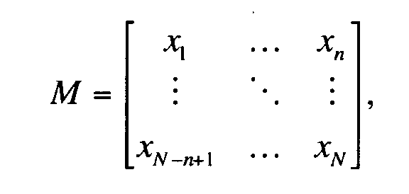
Cette matrice est de rang plein, de sorte qu'on peut l'inverser au cours de l'estimation des différents canaux. This matrix is of full rank, so that it can be inverted during the estimation of the different channels.
Comme décrit précédemment, les symboles de référence de la matrice de
codage M sont émis après répartition espace/fréquence sur l'ensemble des
antennes d'émission, et le vecteur de référence reçu au niveau d'une antenne de
réception, modifié par le canal de transmission, peut s'écrire sous la forme
De nouveau, pour chacune des antennes de réception, on applique au vecteur de référence reçu une transformation mathématique par une matrice de décodage, correspondant à la matrice inverse intégrant une technique d'égalisation au sens du critère MMSE ou ZF de la matrice de codage M, pour estimer le canal de transmission h.Again, for each of the receiving antennas, a mathematical transformation is applied to the reference vector received by a decoding matrix, corresponding to the inverse matrix integrating an equalization technique in the sense of the MMSE or ZF criterion of the coding matrix M , to estimate the transmission channel h .
Si on utilise une technique d'égalisation au sens du critère MMSE, on
obtient :
Comme décrit précédemment, on peut ensuite déterminer les coefficients manquants d'un canal de transmission en appliquant une interpolation temporelle ou fréquentielle (ou les deux) au niveau du récepteur, en utilisant une technique classique d'interpolation.As described previously, the coefficients can then be determined missing from a transmission channel by applying temporal interpolation or frequency (or both) at the receiver, using a technique classic interpolation.
On présente désormais en relation avec les figures 3A et 3B un troisième mode de réalisation de l'invention, s'appliquant plus particulièrement aux systèmes multi-antennes de type MIMO.3A and 3B are now presented in relation to FIGS. embodiment of the invention, applying more particularly to multi-antenna systems of the MIMO type.
Selon ce troisième mode de réalisation, un principe flexible est proposé permettant d'appliquer soit un codage spatio-temporel, soit un codage spatio-fréquentiel, en fonction des caractéristiques du canal de transmission.According to this third embodiment, a flexible principle is proposed allowing to apply either a spatio-temporal coding or a spatio-frequency coding, depending on the characteristics of the transmission channel.
Ainsi, la figure 3A illustre l'émission de 4 symboles de référence et de
leurs conjugués espacés temporellement, dans un système multi-antennes à 4
antennes d'émission, avec X i un symbole de référence référencé 15, X * / i un
symbole de référence conjugué (i un entier relatif et 1 ≤ i ≤ 4), x un symbole de
données, référencé 16.Thus, FIG. 3A illustrates the transmission of 4 reference symbols and their time-spaced conjugates, in a multi-antenna system with 4 transmit antennas, with X i a referenced
La figure 3B illustre l'émission de 4 symboles de référence et de leurs conjugués espacés fréquentiellement, dans un système multi-antennes à 4 antennes d'émission.FIG. 3B illustrates the emission of 4 reference symbols and their conjugates frequently spaced in a 4-way multi-antenna system transmit antennas.
Dans ce troisième mode de réalisation, les symboles de référence, une fois codés par l'intermédiaire de la matrice de codage M, sont répartis suivant l'axe temporel ou l'axe fréquentiel en fonction des propriétés du canal de propagation.In this third embodiment, the reference symbols, once coded via the coding matrix M , are distributed along the time axis or the frequency axis according to the properties of the propagation channel.
On peut ensuite commuter d'un codage spatio-temporel à un codage spatio-fréquentiel.We can then switch from a spatio-temporal coding to a coding space-frequency.
On rappelle que les valeurs choisies pour Δf (espacement entre deux porteuses de référence) et Δt (espacement entre deux symboles de référence à des instants connus) ne sont pas propres au système proposé mais dépendent respectivement de la bande et du temps de cohérence du canal de transmission.It is recalled that the values chosen for Δf (spacing between two reference carriers) and Δt (spacing between two reference symbols to known instants) are not specific to the proposed system but depend on respectively of the band and the coherence time of the transmission channel.
En règle générale, la répartition dans le domaine temporel est plutôt appliquée dans le cas d'un canal variant temporellement, tandis que la répartition fréquentielle est davantage appliquée pour un canal variant fréquentiellement.Generally speaking, the temporal distribution is rather applied in the case of a temporally varying channel, while the distribution Frequency is further applied for a frequency varying channel.
Ainsi, ayant une connaissance du canal à priori ou ayant calculé les valeurs de bande de cohérence et du temps de cohérence du canal, il est possible de commuter entre les deux structures d'insertion de symboles de référence décrites précédemment.Thus, having a prior knowledge of the channel or having calculated the values consistency band and channel coherence time, it is possible to switch between the two reference symbol insertion structures described previously.
L'Homme du Métier étendra facilement l'enseignement de ces trois modes de réalisation à des systèmes présentant un nombre supérieur d'antennes, de même qu'à des systèmes présentant une répartition espace-temps et/ou espace-fréquence différente de celles proposées aux figures 1A, 1B, 2A, 2B, 3A et 3B.The skilled person will easily extend the teaching of these three modes to systems with a higher number of antennas, as well as systems with space-time and / or space-frequency distribution different from those proposed in Figures 1A, 1B, 2A, 2B, 3A and 3B.
Ainsi, selon l'invention, les différentes antennes d'émission émettent, sur une même porteuse et à un même instant, un signal caractérisé par un codage espace-temps et/ou espace-fréquence, ce qui limite la perte en efficacité spectrale. Thus, according to the invention, the different transmission antennas emit, on the same carrier and at the same time, a signal characterized by a coding space-time and / or space-frequency, which limits the loss in spectral efficiency.
Ce signal comprend donc, intrinsèquement, les caractéristiques de l'invention.This signal therefore intrinsically includes the characteristics of the invention.
Finalement, un récepteur peut estimer chacun des canaux de transmission entre les différentes antennes d'émission et de réception à partir de ce codage spécifique et du traitement adéquat décrit précédemment. La technique particulière d'estimation de canal proposée selon l'invention peut d'ailleurs être appliquée au cas d'un système présentant deux antennes d'émission.Finally, a receiver can estimate each of the transmission channels between the different transmit and receive antennas from this coding specific and appropriate treatment described above. The technique particular channel estimation proposed according to the invention can also be applied to the case of a system having two transmitting antennas.
Claims (17)

caractérisé en ce que ledit signal comprend des symboles de référence codés, obtenus après une transformation mathématique de symboles de référence par une matrice de codage M de rendement égal à 1,
de façon à permettre, dans un récepteur, d'estimer au moins deux canaux de transmission correspondant respectivement à chacune desdites antennes d'émission.Digital signal formed of n vectors transmitted respectively with n transmitting antennas, n being strictly greater than 2,
characterized in that said signal comprises coded reference symbols, obtained after a mathematical transformation of reference symbols by a coding matrix M of output equal to 1,
so as to allow, in a receiver, to estimate at least two transmission channels respectively corresponding to each of said transmitting antennas.
caractérisé en ce qu'il comprend une étape de réception d'un vecteur de référence reçu, correspondant à un vecteur de référence émis obtenu par la multiplication de symboles de référence par ladite matrice de codage M, et modifié par au moins un canal de transmission pour chacune desdites antennes d'émission,
et en ce que, pour chacune desdites antennes de réception, ledit vecteur de référence reçu subi une transformation mathématique par une matrice de décodage, inverse de ladite matrice de codage et tenant compte de l'effet d'un canal de transmission associé à ladite antenne de réception, pour fournir une estimation des effets desdits canaux de transmission sur lesdits symboles de référence.A method for estimating at least one transmission channel in a multi-antenna system using n transmit antennas, where n is strictly greater than 2, and at least one receive antenna, which is associated with a vector of source data, n vectors to be emitted respectively by each of said transmitting antennas, using an encoding matrix M , implementing reference symbols, known to at least one receiver and allowing the latter estimating at least two transmission channels respectively corresponding to each of said transmitting antennas,
characterized in that it comprises a step of receiving a received reference vector, corresponding to an emitted reference vector obtained by the multiplication of reference symbols by said coding matrix M , and modified by at least one transmission channel for each of said transmitting antennas,
and in that , for each of said receiving antennas, said received reference vector undergoes a mathematical transformation by a decoding matrix, inverse to said coding matrix and taking into account the effect of a transmission channel associated with said antenna receiving, to provide an estimate of the effects of said transmission channels on said reference symbols.
Priority Applications (10)
| Application Number | Priority Date | Filing Date | Title |
|---|---|---|---|
| EP04364035A EP1589687A1 (en) | 2004-04-23 | 2004-04-23 | Method for sending a signal in a multi-antenna system, corresponding signal and method for channel estimation |
| US11/587,256 US7725091B2 (en) | 2004-04-23 | 2005-04-19 | Method and device for transmitting a signal in a multi-antenna system, signal, and method for estimating the corresponding transmission channels |
| JP2007508934A JP4966190B2 (en) | 2004-04-23 | 2005-04-19 | Method and apparatus for transmitting a signal in a multi-antenna system, signal and method for estimating a corresponding transmission channel |
| BRPI0510038A BRPI0510038B1 (en) | 2004-04-23 | 2005-04-19 | method and device for transmitting a signal in a multiple antenna system, method for estimating the corresponding transmission channels and receiving device in a multiple antenna system |
| KR1020067023092A KR101173472B1 (en) | 2004-04-23 | 2005-04-19 | Method and device for transmitting a signal in a multi-antenna system, signal and method for estimating the corresponding transmission channels |
| CN2005800127533A CN1947370B (en) | 2004-04-23 | 2005-04-19 | Method and device for transmitting a signal in a multi-antenna system, and method for estimating the corresponding transmission channels |
| EP05760052.0A EP1738513B1 (en) | 2004-04-23 | 2005-04-19 | Method for sending a signal in a multi-antenna system, corresponding signal and method for channel estimation |
| PCT/FR2005/000965 WO2005112329A1 (en) | 2004-04-23 | 2005-04-19 | Method and device for transmitting a signal in a multi-antenna system, signal and method for estimating the corresponding transmission channels |
| ZA200608502A ZA200608502B (en) | 2004-04-23 | 2006-10-12 | Method and device for transmitting a signal in a multiantenna system, signal, and method for estimating the corresponding transmission channels |
| US12/756,752 US8358990B2 (en) | 2004-04-23 | 2010-04-08 | Method and device for transmitting a signal in a multi-antenna system, signal, and method for estimating the corresponding transmission channels |
Applications Claiming Priority (1)
| Application Number | Priority Date | Filing Date | Title |
|---|---|---|---|
| EP04364035A EP1589687A1 (en) | 2004-04-23 | 2004-04-23 | Method for sending a signal in a multi-antenna system, corresponding signal and method for channel estimation |
Publications (1)
| Publication Number | Publication Date |
|---|---|
| EP1589687A1 true EP1589687A1 (en) | 2005-10-26 |
Family
ID=34931796
Family Applications (2)
| Application Number | Title | Priority Date | Filing Date |
|---|---|---|---|
| EP04364035A Withdrawn EP1589687A1 (en) | 2004-04-23 | 2004-04-23 | Method for sending a signal in a multi-antenna system, corresponding signal and method for channel estimation |
| EP05760052.0A Active EP1738513B1 (en) | 2004-04-23 | 2005-04-19 | Method for sending a signal in a multi-antenna system, corresponding signal and method for channel estimation |
Family Applications After (1)
| Application Number | Title | Priority Date | Filing Date |
|---|---|---|---|
| EP05760052.0A Active EP1738513B1 (en) | 2004-04-23 | 2005-04-19 | Method for sending a signal in a multi-antenna system, corresponding signal and method for channel estimation |
Country Status (8)
| Country | Link |
|---|---|
| US (2) | US7725091B2 (en) |
| EP (2) | EP1589687A1 (en) |
| JP (1) | JP4966190B2 (en) |
| KR (1) | KR101173472B1 (en) |
| CN (1) | CN1947370B (en) |
| BR (1) | BRPI0510038B1 (en) |
| WO (1) | WO2005112329A1 (en) |
| ZA (1) | ZA200608502B (en) |
Cited By (3)
| Publication number | Priority date | Publication date | Assignee | Title |
|---|---|---|---|---|
| CN100461665C (en) * | 2006-07-31 | 2009-02-11 | 华为技术有限公司 | Method for testing signal in multi-antenna digital wireless communication system |
| CN102104443A (en) * | 2009-12-18 | 2011-06-22 | 华为技术有限公司 | Method and device for network coding in cooperative communication |
| CN101919187B (en) * | 2007-02-27 | 2014-03-12 | 摩托罗拉移动公司 | Method and apparatus for transmission within multi-carrier communication system |
Families Citing this family (11)
| Publication number | Priority date | Publication date | Assignee | Title |
|---|---|---|---|---|
| EP1589687A1 (en) * | 2004-04-23 | 2005-10-26 | France Telecom | Method for sending a signal in a multi-antenna system, corresponding signal and method for channel estimation |
| CN101364827B (en) * | 2007-08-07 | 2012-10-10 | 北京大学 | Data transmission method for multi-antenna communication system |
| US7958065B2 (en) * | 2008-03-18 | 2011-06-07 | International Business Machines Corporation | Resilient classifier for rule-based system |
| US8098750B2 (en) | 2008-07-10 | 2012-01-17 | Infineon Technologies Ag | Method and device for transmitting a plurality of data symbols |
| US8576896B2 (en) | 2009-02-04 | 2013-11-05 | New Jersey Institute Of Technology | Decoding of orthogonal space time codes |
| GB2470768A (en) * | 2009-06-03 | 2010-12-08 | Sony Corp | Receiver for OFDM symbols in a MISO system with Alamouti-type encoding |
| US10152524B2 (en) * | 2012-07-30 | 2018-12-11 | Spatial Digital Systems, Inc. | Wavefront muxing and demuxing for cloud data storage and transport |
| US10120873B2 (en) * | 2010-08-02 | 2018-11-06 | Spatial Digital Systems, Inc. | Survivable cloud data storage and transport |
| US9055433B2 (en) | 2012-01-12 | 2015-06-09 | Facebook, Inc. | Distance-dependent or user-dependent data exchange between wireless communication devices |
| US9008114B2 (en) * | 2012-01-12 | 2015-04-14 | Facebook, Inc. | System and method for distance-dependent data exchange between wireless communication devices |
| US10277293B1 (en) * | 2017-11-21 | 2019-04-30 | Cisco Technology, Inc. | Multi-user-MIMO detection using space-time equalization |
Citations (1)
| Publication number | Priority date | Publication date | Assignee | Title |
|---|---|---|---|---|
| US6307882B1 (en) * | 1998-07-10 | 2001-10-23 | Lucent Technologies Inc. | Determining channel characteristics in a space-time architecture wireless communication system having multi-element antennas |
Family Cites Families (13)
| Publication number | Priority date | Publication date | Assignee | Title |
|---|---|---|---|---|
| JPH06350854A (en) * | 1993-06-10 | 1994-12-22 | Matsushita Electric Ind Co Ltd | Picture compression encoding device |
| US6430231B1 (en) * | 1997-11-11 | 2002-08-06 | At&T Corp. | Generalized orthogonal designs for space-time codes for wireless communication |
| US6088408A (en) * | 1998-11-06 | 2000-07-11 | At & T Corp. | Decoding for generalized orthogonal designs for space-time codes for wireless communication |
| US6145110A (en) * | 1998-06-22 | 2000-11-07 | Ericsson Inc. | Digital data decoder that derives codeword estimates from soft data |
| US6226330B1 (en) * | 1998-07-16 | 2001-05-01 | Silicon Graphics, Inc. | Eigen-mode encoding of signals in a data group |
| US6760479B1 (en) * | 1999-10-22 | 2004-07-06 | Research Foundation Of The City University Of New York | Super predictive-transform coding |
| FR2820574B1 (en) * | 2001-02-08 | 2005-08-05 | Wavecom Sa | METHOD FOR EXTRACTING A REFERENCE SYMBOL PATTERN FOR ESTIMATING THE TRANSFER FUNCTION OF A TRANSMIT CHANNEL, SIGNAL, DEVICE AND CORRESPONDING METHODS |
| KR100507519B1 (en) * | 2002-12-13 | 2005-08-17 | 한국전자통신연구원 | Method and Apparatus for Signal Constitution for Downlink of OFDMA Based Cellular Systems |
| KR100640349B1 (en) * | 2003-01-02 | 2006-10-30 | 삼성전자주식회사 | Transmitting and receiving apparatus for wireless telecommunication system having 3 transmit antennas |
| EP1589687A1 (en) * | 2004-04-23 | 2005-10-26 | France Telecom | Method for sending a signal in a multi-antenna system, corresponding signal and method for channel estimation |
| EP1856871A1 (en) * | 2005-03-08 | 2007-11-21 | France Telecom S.A. | Method for the iterative reception of a multicarrier signal with interference cancellation, and corresponding receiver and computer program |
| US7219289B2 (en) * | 2005-03-15 | 2007-05-15 | Tandberg Data Corporation | Multiply redundant raid system and XOR-efficient method and apparatus for implementing the same |
| JP2011512100A (en) * | 2008-02-11 | 2011-04-14 | ゼットティーイー (ユーエスエー) インコーポレイテッド | Method and system for integrating and encoding a plurality of independent information messages |
-
2004
- 2004-04-23 EP EP04364035A patent/EP1589687A1/en not_active Withdrawn
-
2005
- 2005-04-19 BR BRPI0510038A patent/BRPI0510038B1/en active IP Right Grant
- 2005-04-19 US US11/587,256 patent/US7725091B2/en active Active
- 2005-04-19 WO PCT/FR2005/000965 patent/WO2005112329A1/en active Application Filing
- 2005-04-19 EP EP05760052.0A patent/EP1738513B1/en active Active
- 2005-04-19 CN CN2005800127533A patent/CN1947370B/en active Active
- 2005-04-19 KR KR1020067023092A patent/KR101173472B1/en active IP Right Grant
- 2005-04-19 JP JP2007508934A patent/JP4966190B2/en active Active
-
2006
- 2006-10-12 ZA ZA200608502A patent/ZA200608502B/en unknown
-
2010
- 2010-04-08 US US12/756,752 patent/US8358990B2/en active Active
Patent Citations (1)
| Publication number | Priority date | Publication date | Assignee | Title |
|---|---|---|---|---|
| US6307882B1 (en) * | 1998-07-10 | 2001-10-23 | Lucent Technologies Inc. | Determining channel characteristics in a space-time architecture wireless communication system having multi-element antennas |
Non-Patent Citations (5)
| Title |
|---|
| CHAU YUEN ET AL: "Decoding of quasi-orthogonal space-time block code with noise whitening", 14TH IEEE 2003 INTERNATIONAL SYMPOSIUM ON PERSONAL, INDOOR AND MOBILE RADIO COMMUNICATION PROCEEDINGS, vol. 2, 7 September 2003 (2003-09-07), pages 2166 - 2170, XP010677944 * |
| HOTTINEN A ET AL: "A ROANDOMIZATION TECHNIQUE FOR NON-ORTHOGONAL SPACE-TIME BLOCK CODES", VTC 2001 SPRING. IEEE VTS 53RD. VEHICULAR TECHNOLOGY CONFERENCE. RHODES, GREECE, MAY 6 - 9, 2001, IEEE VEHICULAR TECHNOLGY CONFERENCE, NEW YORK, NY : IEEE, US, vol. VOL. 2 OF 4. CONF. 53, 6 May 2001 (2001-05-06), pages 1479 - 1482, XP001067210, ISBN: 0-7803-6728-6 * |
| JAFARKHANI H: "A quasi-orthogonal space-time block code", 2000 IEEE, vol. 1, 23 September 2000 (2000-09-23), pages 42 - 45, XP010532464 * |
| NAGUIB A F ET AL: "Space-time coded modulation for high data rate wireless communications", GLOBAL TELECOMMUNICATIONS CONFERENCE, 1997. GLOBECOM '97., IEEE PHOENIX, AZ, USA 3-8 NOV. 1997, NEW YORK, NY, USA,IEEE, US, 3 November 1997 (1997-11-03), pages 102 - 109, XP010254629, ISBN: 0-7803-4198-8 * |
| TIRKKONEN O ET AL: "Minimal non-orthogonality rate 1 space-time block code for 3+ Tx antennas", IEEE 6TH SYMPOSIUM ON SPREAD-SPECTRUM TECHNIQUES AND APPLICATIONS, vol. 2, 6 September 2000 (2000-09-06), pages 429 - 432, XP010516615 * |
Cited By (4)
| Publication number | Priority date | Publication date | Assignee | Title |
|---|---|---|---|---|
| CN100461665C (en) * | 2006-07-31 | 2009-02-11 | 华为技术有限公司 | Method for testing signal in multi-antenna digital wireless communication system |
| CN101919187B (en) * | 2007-02-27 | 2014-03-12 | 摩托罗拉移动公司 | Method and apparatus for transmission within multi-carrier communication system |
| CN102104443A (en) * | 2009-12-18 | 2011-06-22 | 华为技术有限公司 | Method and device for network coding in cooperative communication |
| CN102104443B (en) * | 2009-12-18 | 2013-04-24 | 华为技术有限公司 | Method and device for network coding in cooperative communication |
Also Published As
| Publication number | Publication date |
|---|---|
| CN1947370A (en) | 2007-04-11 |
| EP1738513A1 (en) | 2007-01-03 |
| BRPI0510038B1 (en) | 2019-01-08 |
| US7725091B2 (en) | 2010-05-25 |
| US20070238420A1 (en) | 2007-10-11 |
| ZA200608502B (en) | 2008-04-30 |
| JP4966190B2 (en) | 2012-07-04 |
| EP1738513B1 (en) | 2017-04-12 |
| WO2005112329A1 (en) | 2005-11-24 |
| JP2007534250A (en) | 2007-11-22 |
| KR20070004947A (en) | 2007-01-09 |
| KR101173472B1 (en) | 2012-08-14 |
| BRPI0510038A (en) | 2007-10-02 |
| US20100195761A1 (en) | 2010-08-05 |
| CN1947370B (en) | 2011-04-27 |
| US8358990B2 (en) | 2013-01-22 |
Similar Documents
| Publication | Publication Date | Title |
|---|---|---|
| EP1738513B1 (en) | Method for sending a signal in a multi-antenna system, corresponding signal and method for channel estimation | |
| EP1690361B1 (en) | Method for the multi-antenna transmission of a linearly-precoded signal, corresponding devices, signal and reception method | |
| EP1981203B1 (en) | Method and multiple-antenna device for signal transmission | |
| EP1212872B1 (en) | Receiver with orthogonal frequency distribution multiplexing having iterative channel estimation and corresponding method | |
| EP2099137A2 (en) | Differential spatial-temporal coding method | |
| FR2774831A1 (en) | ADAPTIVE SIGNAL RECEIVER FOR CULTIVATED PULTIPLE ACCESS COMMUNICATION SYSTEM | |
| EP2026475A1 (en) | Space-time coding/decoding method for pulse type multi-antenna communication system | |
| EP1668794B1 (en) | Method for a multi-antenna transmission of a space-time block coded signal | |
| WO2001020840A1 (en) | Equalising method in receivers using a combination of multiple carrier and code division multiple access modulating techniques | |
| EP2427991B1 (en) | Pre-equalizing method using fdd time reversal | |
| EP1260071B1 (en) | Method and device for estimating channel propagation | |
| FR2901434A1 (en) | METHOD FOR DECODING 2X2 SPATIO-TEMPORAL CODES, ESPECIALLY OF THE GOLDEN CODE TYPE | |
| EP1856871A1 (en) | Method for the iterative reception of a multicarrier signal with interference cancellation, and corresponding receiver and computer program | |
| FR2891682A1 (en) | Multi-carrier radio signal receiving method for e.g. orthogonal frequency division multiplexing signal reception system, involves obtaining values of estimated noise power from determined estimated noise power values | |
| KR20050065296A (en) | Differential space-time block codes for up to 8 transmit antennas | |
| EP1661286B1 (en) | Receiver and method for decoding a coded signal with the aid of a space-time or space-frequency coding matrix | |
| EP1603264A1 (en) | Method and system for receiving a linearly precoded and channel coded signal | |
| EP2514113B1 (en) | Method for transmitting a source signal, method for receiving a transmitted signal, corresponding transmitter, receiver, signal and computer programs | |
| EP1623514B1 (en) | Spread-spectrum modulator and demodulator | |
| EP2524446B1 (en) | Method for transmitting a digital signal for a distributed system ann corresponding programmable product and relay apparatus | |
| FR2823623A1 (en) | Bidirectional digital transmission system having multiple carrier signals base station/terminal passed with estimation step transfer function analysing down signal received/delivering estimation information/carrying out predistortion. | |
| Abou-Rjeily et al. | Differential space-time ultra-wideband communications | |
| WO2005109708A1 (en) | Method for determination of code spread used in a cdma signal and corresponding communication device | |
| EP3843308A1 (en) | Method and system for receiving and equalising a signal emitted with alamouti coding by blocks in the presence of possible interference | |
| WO2007060232A1 (en) | Method for transmitting and receiving a signal having been subjected to a linear precoding in a multiple-antenna system |
Legal Events
| Date | Code | Title | Description |
|---|---|---|---|
| PUAI | Public reference made under article 153(3) epc to a published international application that has entered the european phase |
Free format text: ORIGINAL CODE: 0009012 |
|
| AK | Designated contracting states |
Kind code of ref document: A1 Designated state(s): AT BE BG CH CY CZ DE DK EE ES FI FR GB GR HU IE IT LI LU MC NL PL PT RO SE SI SK TR |
|
| AX | Request for extension of the european patent |
Extension state: AL HR LT LV MK |
|
| 17P | Request for examination filed |
Effective date: 20060120 |
|
| STAA | Information on the status of an ep patent application or granted ep patent |
Free format text: STATUS: THE APPLICATION HAS BEEN WITHDRAWN |
|
| AKX | Designation fees paid |
Designated state(s): AT BE BG CH CY CZ DE DK EE ES FI FR GB GR HU IE IT LI LU MC NL PL PT RO SE SI SK TR |
|
| 18W | Application withdrawn |
Effective date: 20060621 |