EP1587282A2 - Data overlay, self-organized metadata overlay, and application level multicasting - Google Patents
Data overlay, self-organized metadata overlay, and application level multicasting Download PDFInfo
- Publication number
- EP1587282A2 EP1587282A2 EP05102991A EP05102991A EP1587282A2 EP 1587282 A2 EP1587282 A2 EP 1587282A2 EP 05102991 A EP05102991 A EP 05102991A EP 05102991 A EP05102991 A EP 05102991A EP 1587282 A2 EP1587282 A2 EP 1587282A2
- Authority
- EP
- European Patent Office
- Prior art keywords
- tree
- node
- dht
- nodes
- data
- Prior art date
- Legal status (The legal status is an assumption and is not a legal conclusion. Google has not performed a legal analysis and makes no representation as to the accuracy of the status listed.)
- Granted
Links
- 238000000034 method Methods 0.000 claims description 69
- 238000005457 optimization Methods 0.000 claims description 14
- 238000012545 processing Methods 0.000 claims description 11
- 238000004891 communication Methods 0.000 claims description 8
- 238000013507 mapping Methods 0.000 claims description 8
- 238000003780 insertion Methods 0.000 claims description 6
- 230000037431 insertion Effects 0.000 claims description 6
- 230000005540 biological transmission Effects 0.000 claims 4
- 101150039167 Bex3 gene Proteins 0.000 claims 1
- 241001529739 Prunella <angiosperm> Species 0.000 abstract description 3
- 235000008113 selfheal Nutrition 0.000 abstract description 3
- 230000015654 memory Effects 0.000 description 14
- 230000006870 function Effects 0.000 description 11
- 238000003860 storage Methods 0.000 description 10
- 238000000638 solvent extraction Methods 0.000 description 9
- 230000007246 mechanism Effects 0.000 description 8
- 238000005192 partition Methods 0.000 description 8
- 230000008569 process Effects 0.000 description 7
- 238000012544 monitoring process Methods 0.000 description 6
- 230000003287 optical effect Effects 0.000 description 6
- 230000002776 aggregation Effects 0.000 description 5
- 238000004220 aggregation Methods 0.000 description 5
- 238000013459 approach Methods 0.000 description 5
- 230000000694 effects Effects 0.000 description 4
- 230000004048 modification Effects 0.000 description 4
- 238000012986 modification Methods 0.000 description 4
- 230000008901 benefit Effects 0.000 description 3
- 230000006872 improvement Effects 0.000 description 3
- 238000005304 joining Methods 0.000 description 3
- 230000006855 networking Effects 0.000 description 3
- 235000014594 pastries Nutrition 0.000 description 3
- 230000004044 response Effects 0.000 description 3
- 239000013598 vector Substances 0.000 description 3
- 235000008694 Humulus lupulus Nutrition 0.000 description 2
- 230000009471 action Effects 0.000 description 2
- 230000003190 augmentative effect Effects 0.000 description 2
- 230000007423 decrease Effects 0.000 description 2
- 238000009826 distribution Methods 0.000 description 2
- 230000035876 healing Effects 0.000 description 2
- 230000003993 interaction Effects 0.000 description 2
- 230000002093 peripheral effect Effects 0.000 description 2
- 238000011176 pooling Methods 0.000 description 2
- 230000000750 progressive effect Effects 0.000 description 2
- 230000000644 propagated effect Effects 0.000 description 2
- 238000012546 transfer Methods 0.000 description 2
- 230000004931 aggregating effect Effects 0.000 description 1
- 230000006399 behavior Effects 0.000 description 1
- 230000009286 beneficial effect Effects 0.000 description 1
- 230000001427 coherent effect Effects 0.000 description 1
- 238000010276 construction Methods 0.000 description 1
- 238000007796 conventional method Methods 0.000 description 1
- 239000006185 dispersion Substances 0.000 description 1
- 230000002349 favourable effect Effects 0.000 description 1
- 239000004615 ingredient Substances 0.000 description 1
- 230000005055 memory storage Effects 0.000 description 1
- 239000000203 mixture Substances 0.000 description 1
- 230000008447 perception Effects 0.000 description 1
- 230000000737 periodic effect Effects 0.000 description 1
- 239000000523 sample Substances 0.000 description 1
- 238000000926 separation method Methods 0.000 description 1
- 230000003068 static effect Effects 0.000 description 1
- 230000001360 synchronised effect Effects 0.000 description 1
- 230000001960 triggered effect Effects 0.000 description 1
- 238000011144 upstream manufacturing Methods 0.000 description 1
- 238000012800 visualization Methods 0.000 description 1
Images


Classifications
-
- H—ELECTRICITY
- H04—ELECTRIC COMMUNICATION TECHNIQUE
- H04L—TRANSMISSION OF DIGITAL INFORMATION, e.g. TELEGRAPHIC COMMUNICATION
- H04L12/00—Data switching networks
- H04L12/28—Data switching networks characterised by path configuration, e.g. LAN [Local Area Networks] or WAN [Wide Area Networks]
-
- H—ELECTRICITY
- H04—ELECTRIC COMMUNICATION TECHNIQUE
- H04L—TRANSMISSION OF DIGITAL INFORMATION, e.g. TELEGRAPHIC COMMUNICATION
- H04L67/00—Network arrangements or protocols for supporting network services or applications
- H04L67/50—Network services
- H04L67/56—Provisioning of proxy services
- H04L67/561—Adding application-functional data or data for application control, e.g. adding metadata
-
- H—ELECTRICITY
- H04—ELECTRIC COMMUNICATION TECHNIQUE
- H04L—TRANSMISSION OF DIGITAL INFORMATION, e.g. TELEGRAPHIC COMMUNICATION
- H04L67/00—Network arrangements or protocols for supporting network services or applications
- H04L67/50—Network services
- H04L67/56—Provisioning of proxy services
- H04L67/564—Enhancement of application control based on intercepted application data
-
- H—ELECTRICITY
- H04—ELECTRIC COMMUNICATION TECHNIQUE
- H04L—TRANSMISSION OF DIGITAL INFORMATION, e.g. TELEGRAPHIC COMMUNICATION
- H04L67/00—Network arrangements or protocols for supporting network services or applications
- H04L67/50—Network services
- H04L67/60—Scheduling or organising the servicing of application requests, e.g. requests for application data transmissions using the analysis and optimisation of the required network resources
- H04L67/63—Routing a service request depending on the request content or context
-
- Y—GENERAL TAGGING OF NEW TECHNOLOGICAL DEVELOPMENTS; GENERAL TAGGING OF CROSS-SECTIONAL TECHNOLOGIES SPANNING OVER SEVERAL SECTIONS OF THE IPC; TECHNICAL SUBJECTS COVERED BY FORMER USPC CROSS-REFERENCE ART COLLECTIONS [XRACs] AND DIGESTS
- Y10—TECHNICAL SUBJECTS COVERED BY FORMER USPC
- Y10S—TECHNICAL SUBJECTS COVERED BY FORMER USPC CROSS-REFERENCE ART COLLECTIONS [XRACs] AND DIGESTS
- Y10S707/00—Data processing: database and file management or data structures
- Y10S707/99941—Database schema or data structure
- Y10S707/99942—Manipulating data structure, e.g. compression, compaction, compilation
-
- Y—GENERAL TAGGING OF NEW TECHNOLOGICAL DEVELOPMENTS; GENERAL TAGGING OF CROSS-SECTIONAL TECHNOLOGIES SPANNING OVER SEVERAL SECTIONS OF THE IPC; TECHNICAL SUBJECTS COVERED BY FORMER USPC CROSS-REFERENCE ART COLLECTIONS [XRACs] AND DIGESTS
- Y10—TECHNICAL SUBJECTS COVERED BY FORMER USPC
- Y10S—TECHNICAL SUBJECTS COVERED BY FORMER USPC CROSS-REFERENCE ART COLLECTIONS [XRACs] AND DIGESTS
- Y10S707/00—Data processing: database and file management or data structures
- Y10S707/99941—Database schema or data structure
- Y10S707/99943—Generating database or data structure, e.g. via user interface
Definitions
- This invention relates to a distributed data structure and to a technique for utilizing the data structure to interact with a peer-to-peer system, as well as using the technique with application level multicasting.
- Peer-to-peer (P2P) systems employ a network which connects participating machines having equal or similar capabilities and responsibilities. These systems perform tasks without the coordination of a conventional server (or with minimal set-up coordination by a server).
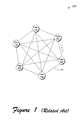
- Fig. 1 shows a high-level depiction of a P2P system 100.
- the system 100 includes a collection of peer entities (102-112) having equal or similar capabilities and responsibilities.
- the peer entities (102-112) may correspond to independent personal computer devices coupled together via an Internet or intranet.
- the peer entities (102-112) can directly transfer files or other information between themselves (as indicated by exemplary communication path 114) without the aid of a server.
- a general introduction to P2P systems can be found in D. S.
- DHT distributed hash table
- a distributed hash table refers to a hash table that is distributed over plural locations, such as distributed over plural stores associated with different computer devices.
- a distributed hash table specifies a plurality of DHT nodes having respective assigned IDs.
- the DHT nodes collectively define an abstract DHT logical space. An object can be inserted into or retrieved from this DHT logical space by subjecting this object to a hashing function to produce a key. This key is then used to locate a particular target node ID in the DHT logical space that will receive the object or from which the object can be retrieved.
- each DHT node is associated with a range of keys; an object is added to or retrieved from a particular DHT node depending on whether the object's key falls within the range of keys associated with that particular DHT node.
- DHT nodes can freely join and leave the DHT logical space (e.g., corresponding to computer devices joining and leaving the P2P system, respectively), so functionality must be provided to address these events.
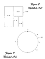
- FIG. 2 shows a Content Addressable Network (CAN) strategy, e.g., as described in S. Ratnasamy, P. Francis, M. Handley, R. Karp, and S. Shenker, "A Scalable Content-Addressable Network,” ACM SigComm 2001, San Diego, CA, USA, Aug. 2001.
- This strategy models the DHT logical space as a D-dimensional Cartesian space 200.
- the CAN strategy partitions the space 200 as nodes join the DHT space 200. For instance, when node n1 joins, the CAN strategy allocates the entire space 200 to this node.
- the CAN strategy divides the space 200 into two halves and allocates each half to nodes n1 and n2, respectively.
- the CAN strategy divides the right half into upper and lower quarters, assigning the upper quarter to node n2 and the lower quarter to node n3.
- the CAN strategy divides the lower right quarter into a left eighth (which is assigned to node n3) and a right eighth (which is assigned to node n4). This procedure is repeated as many times as necessary to dynamically account for nodes being adding and removed.
- the resultant partitions define logical spaces used to insert and retrieve objects into and from the distributed hash table. A node can be said to "own" the objects that map to its space.
- Fig. 3 shows another strategy referred to as CHORD (e.g., as described in I. Stoica, R. Morris, D. Karger, M.F. Kaashoek, and H. Balakrishnan, "Chord: a Scalable Peer-To-Peer Lookup Service for Internet Applications," ACM SigComm 2001, San Diego, CA, USA, Aug. 2001.
- the DHT logical space is structured as circular space 300.
- DHT nodes are assigned IDs and added to the circular DHT logical space 300 based of their assigned IDs. For instance, exemplary DHT nodes n1, n2, n3, n4, and n5 shown in Fig.
- the DHT nodes partition the DHT logical space 300 as they are added, defining multiple subspaces or zones. These zones define the objects that each node "owns.” For instance, to insert an object into a distributed hash table that is governed by the DHT strategy shown in Fig. 3, the object is subjected to a hashing function to produce a key. The object is then stored at the DHT node have a zone assigned to that key (e.g., at the DHT node which encompasses a range of keys that include the object's key). In both the cases of Fig. 2 and Fig.
- a variety of lookup strategies can be used to quickly find a particular node in the P2P system.
- the lookup strategies involve making several "hops" in the DHT logical space to narrow in on the desired target DHT node.
- Various mechanisms are commonly provided to expedite this search. For instance, each DHT node in the CHORD strategy stores the IDs of a set of other DHT nodes. These other IDs can increase in exponential fashion, establishing so-called "fingers” that probe out into the logical space 300. This allows the lookup procedure to quickly locate a desired DHT node with a small number of hops.
- Figs. 2 and 3 provide merely a high level overview of two exemplary known DHT routing strategies. There are many other strategies. For instance, another popular routing strategy is the PASTRY routing strategy, as described in A. Rowstron and P. Druschel, "Pastry: Scalable, Distributed Object Location and Routing for Large-Scale Peer-To-Peer Systems," 18th FIFP/ACM International Conference on Distributed Systems Platforms (Middleware), Heidelberg, Germany, Nov. 2001.
- P2P systems offer many benefits over conventional client-server strategies. For instance, P2P systems have the ability to automatically and freely expand and contract without central coordination. But this lack of supervisory coordination also poses various challenges. For instance, it may be desirable to have the P2P system act in concert to perform some global function. In various instances, it may be desirable to collect data from the participants of the P2P system. Or it may be desirable to disseminate information to the participants in the P2P system. With a client-server approach, a server can simply poll its clients to collect information from its clients, or broadcast information to its clients to disseminate information to its clients. But data gathering and dissemination becomes more problematic in a P2P system because it is formed by a loose alliance of interconnected peers that can freely come and go. Adding centralized conventional reporting functionality may have the effect of complicating the P2P system, and thus reducing its flexibility and utility.
- a method for building a data overlay.
- the method includes providing a distributed hash table (DHT) that governs the insertion and retrieval of objects into and from a peer-to-peer system, wherein the distributed hash table includes a logical space including a plurality of DHT nodes having an associated plurality of DHT zones.
- the method also includes building the data overlay as a data structure on top of the logical space of the distributed hash table by associating objects in the data structure with the DHT nodes, and by establishing links between the objects in the data structure.
- the data overlay has a topology of a tree, where the tree has tree nodes associated with respective DHT nodes. Each tree node has a respective tree node zone associated therewith which corresponds to a part of the logical space of the distributed hash table.
- Machines are mapped to the logical space of the DHT. Each machine corresponds to one or more of more of the tree node zones. Each machine selects as its representative node, from the one or more tree node zones corresponding to it, the tree node corresponding to the largest size tree node zone. Each representative node selects as its parent node another representative node that is the representative node for an adjacent tree node zone that has a larger size.
- Metadata can be gathering metadata at each machine.
- the gathered metadata can be sent from each machine to its representative node and those representative nodes can send the metadata so received to their respective parent node.
- the metadata received at the highest node in the tree e.g., the root node
- the meta data can be information regarding the operation of each machine and the processed metadata can be instructions that can govern the operation of each machine.
- Fig. 1 shows a conventional peer-to-peer (P2P) system.
- P2P peer-to-peer
- Fig. 2 shows a conventional CAN routing strategy.
- Fig. 3 shows a conventional CHORD routing strategy.
- Fig. 4 shows a conventional technique for linking two objects of a data structure in the context of a local machine environment.
- Fig. 5 shows an exemplary technique for linking two objects of a data structure in a P2P distributed hash table (DHT) environment, where the two objects are associated with two different nodes in the P2P DHT environment, and where the linking technique forms the basis of a data overlay placed "on top" of the DHT.
- DHT distributed hash table
- Fig. 6 shows a simple P2P DHT that includes a ring, a zone, and a basic routing table that records r neighbors to each side, where hashing assigns zones to DHT nodes.
- Fig. 7 shows an exemplary tree structure constructed using the concept of a data overlay depicted in Fig. 5, where the tree structure is referred to a Self-Organized Metadata Overlay (SOMO).
- SOMO Self-Organized Metadata Overlay
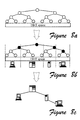
- Figs. 8a-8c depict progressive schematic views of a process for building a SOMO from the bottom up, where Fig. 8a shows the building of a logical tree as a frame of reference, Fig. 8b shows the finding of representative virtual nodes, and Fig. 8c shows a mapping of the logical tree to physical machines.
- Figs. 9a-9c depict progressive schematic views of a self-scaling process for healing the bottom up SOMO depicted in Fig. 8c, where Fig. 9a shows the bottom up SOMO depicted in Fig. 8c, Fig. 9b shows the addition of a physical machine for which a corresponding representative virtual node is found in the logical tree, and Fig. 9c shows a mapping of the revised logical tree to all of the physical machines.
- Fig. 10a shows the combination of the capabilities of a DHT for pooling resources and a bottom up SOMO to collectively make a resource pool.
- Fig. 10b shows an exemplary application of the SOMO tree structure of Fig. 7 to the collection of information from, and dissemination of information to, the participants of the P2P system.
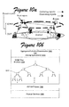
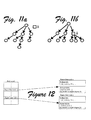
- Fig. 11a depicts a schematic arrangement for application level multicasting
- Fig. 11b shows an improvement upon the arrangement seen in Fig. 11a by the use of a helper node in a resource pool, where circles represent original members of an application level multicasting session and a square represents an available peer having a large degree.
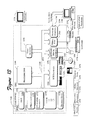
- Fig. 12 depicts a SOMO report structure for scheduling a single application level multicasting session, where each node publishes their network coordinates as well as bandwidth constraints in their reports to SOMO.
- Fig. 13 shows an exemplary computer used to implement a participant of a P2P system, where the P2P system includes a data overlay built on top of its DHT.
- Series 100 numbers refer to features originally found in Fig. 1
- series 200 numbers refer to features originally found in Fig. 2
- series 300 numbers refer to features originally found in Fig. 3, and so on.
- the strategies described herein pertain to a data structure built "on top" of a distributed hash table (DHT) used in a peer-to-peer (P2P) system.
- DHT distributed hash table
- P2P peer-to-peer
- the term peer-to-peer (P2P) system can describe any interconnection of participants in which the participants can directly interact with others, such as the interconnection network 100 shown in Fig. 1. In one implementation, the P2P system does not require the assistance of any server-type entities.
- the participants can include any kind of entity, including personal computers, laptop computers, personal digital assistants, application-specific computing devices, and so on.
- the participants can communicate with each other via any combination of routing infrastructure, such as hardwired and/or wireless communication routing mechanisms, various routers, gateways, etc. Further, the participants can communicate with each other through any combination of network protocols, such as TCP/IP (e.g., as provided by the Internet or an intranet).
- TCP/IP network protocols
- any of the functions described herein can be implemented using software, firmware (e.g., fixed logic circuitry), manual processing, or a combination of these implementations.
- firmware e.g., fixed logic circuitry
- logic or “module” as used herein generally represents software, firmware, or a combination of software and firmware.
- firmware e.g., fixed logic circuitry
- firmware e.g., fixed logic circuitry
- firmware e.g., fixed logic circuitry
- Section A describes a general data overlay structure that can be built "on top" of a P2P DHT
- Section B describes a Self-Organized Metadata Overlay, or "SOMO”
- Section C describes applying the SOMO for gathering and dissemination of information in a P2P system
- Section D describes Application Level Multicasting (ALM) using the P2P DHT
- Section E describes using an exemplary P2P participant that can be used in the type of P2P DHT system with ALM as described in Sections A-D.
- ALM Application Level Multicasting
- a data overlay is a data structure comprised of objects.
- the data structure is implemented "on top" of a distributed hash table.
- DHT provides a technique for inserting objects into and retrieving objects from a distributed store provided by a P2P system. It performs this task by defining a collection of DHT nodes within a logical DHT space. That is, the DHT technique assigns each DHT node to a predetermined portion of the DHT logical space, referred to as the "zone" of the DHT node.
- the zone For example, in the CHORD technique, a particular DHT node's zone can be interpreted as the span defined between that particular DHT node and its adjacent node in a circular DHT logical space (e.g., as shown in Fig.
- An object is stored by hashing it to produce a key, and then using this key to associate the object with a particular node ID in the DHT logical space.
- the object is retrieved from the DHT logical space in a related manner.
- the associated zones ultimately map into real machines (e.g., computer devices and associated file storage systems), although there need not be a one to one relationship between nodes and machines.
- the data overlay is implemented "on top" of the DHT in the sense that its objects are associated with nodes in the DHT logical space. Further, an application traverses (or routes) from one object to another in the data overlay's data structure using the underlying protocols and services of the P2P DHT. More specifically, for frame of reference, consider the conventional case of Fig. 4 of a single machine environment 402.
- a data structure includes two objects, a 404 and b 406, implemented in the storage provided by a single machine.
- An object broadly represents any unit of any type of information; in a conventional case, for instance, an object can correspond to a database record, e.g., a document.
- object a 404 contains a pointer 408 that references object b 406.
- Fig. 5 shows the implementation of a data overlay in the context of a P2P DHT environment 502.
- DHT node x 504 hosts object a 506, and DHT node y 508 hosts object b 510.
- object a 506 references object b 510.
- object a 506 can link to object b 510 by storing the key that is used to access object b 510. This key is established when object b 510 is created.
- the referencing scheme includes two fields.
- a first field 512 contains a hardwired address that points from object a 506 to object b 510. This field is referred to as a.foo.key.
- a second field 514 contains a soft-state reference that identifies the last known DHT node (e.g., node y 508) that hosts object b 510. This field is referred to as a.foo.host. The second field 514 thus serves as a routing shortcut to access object b 510.
- the data overlay itself can be regarded as a distributed data structure. Although the data structure is distributed, it may be desirable to store it in such a manner that its objects are not unduly widely geographically dispersed. This can be achieved by generating the keys of a 506 and b 510 so that they are close to each other. This makes it more likely that the P2P DHT system will associate these keys with the same node in the P2P system or in closely related nodes in the P2P DHT system.
- the data overlay also provides a collection of primitives used to manipulate pointers and objects in its data structure. More specifically, these primitives include a procedure (setref) for establishing a reference from object a to another object b , a procedure (deref) for returning an object pointed to by object a , and a procedure for deleting (delete) an object pointed to by object a .
- these primitives include a procedure (setref) for establishing a reference from object a to another object b , a procedure (deref) for returning an object pointed to by object a , and a procedure for deleting (delete) an object pointed to by object a .
- the primitives can use a DHT_insert service for inserting an object into the DHT logical space.
- the primitives can use a DHT_lookup service for using a predetermined DHT routing procedure to find an object based on its key in the DHT logical space (such as the exponential finger lookup structure used by CHORD).
- the primitives can also use a DHT_direct procedure for directly accessing an object if the DHT node that stores the object is known in advance. In other words, DHT_direct bypasses the normal DHT_lookup routing procedure and directly seeks the node that hosts the object given its key. Both DHT_lookup and DHT_insert will, as a side effect, return the DHT node in the DHT that currently hosts the target object.
- the data overlay can be implemented using its underlying DHT service by modifying whatever library routines are used to create objects so that these routines also establish the pointers described above as attributes of the objects.
- the library routines should also be modified to accommodate the primitives described above for setting a reference, returning an object pointed to by a reference, and deleting an object pointed to by a reference.
- the DHT is designed to self-organize as DHT nodes are added to and deleted from the DHT logical space (related to real machines joining and leaving the P2P system, respectively).
- the DHT is also designed to automatically "heal" itself in response to DHT nodes being added to and deleted from the DHT logical space (such as by reestablishing links between nodes, transferring objects between nodes, etc.).
- the data overlay can also adopt the features of self-organizing and self-healing. More specifically, the data overlay can be configured such that it is self organizing and self-healing on the same scale as the underlying DHT.
- various applications can be ported to run on top of a P2P DHT, giving these applications the illusion of an infinite storage space (e.g., giving the impression of a single resource pool having a large size encompassing the nodes of the DHT logical space).
- This storage space can broadly include memory heaps of machines that are participating in the P2P DHT system.
- the host routing shortcut e.g., a.foo.host
- a very large logical space (e.g., 160-bits) is assumed. Nodes join this space with random IDs and thus partition the spaced uniformly.
- the ID can be, for instance, a MD5 hash over a node's IP address.
- An ordered set of nodes allows a node's responsible zone to be strictly defined.
- Let p and q be a node x's predecessor and successor, respectively.
- One definition of a node's zone is simply the space between the ID of its immediate predecessor ID (non-inclusive) and its own ID. In other words: zone ( x ) ⁇ ( ID ( p ), ID( x )].
- Figure 6 depicts a way to see a DHT as a logical space where each node occupies a logical position in the logical space, where the logical space is divided up. As such, each node needs to remember a few of its adjacent neighbors in order to make the logical space coherent.
- a new machine picks a random ID and joins the DHT. The new machine contacts any of the nodes, seeks to find a position, and then partitions the logical space for itself so that the tree self-organizes and is self-healing.
- the self-healing aspect occurs when a machine departs because its leaving is monitored by its adjacent neighbor machines, which departure is detected when the departing machine no longer sends a "heart beat" communication to indicate its presence. A new neighboring machine can then be taken on.
- Figure 6 can also be seen as depicting essentially how consistent hashing assigns zones to DHT nodes, where a ring, a zone, and a basic routing table are used.
- each node records r neighbors to each side in the rudimentary routing table that is commonly known as a leaf-set. Neighbors exchange periodic communications to indicate their presence (e.g., "heartbeats"), as well as to update their routing tables when a node joins/leaves or when events occur.
- This base ring seen in Figure 6, is a simple P2P DHT. If one imagines the zone being a hash bucket in an ordinary hash table, then the ring is a DHT. Given a key in the space, one can always resolve which node is being responsible.
- the lookup performance is O( N ) in this simple ring structure, where N is the number of nodes in the system.
- Algorithms built upon the above concept achieves O(log N ) performance with either O(log N ) or even constant states (i.e., the routing table entries).
- Representative systems include the CAN partitioning scheme, the CHORD partitioning scheme, etc.
- the whole system of a DHT is self-organizing with an overhead typically in the order of O(log N ).
- a DHT is the virtualization of a space where both resources and other entities (such as documents stored in DHT) live together.
- the above described data overlay provides a framework for building an arbitrary data structure on top of a DHT.
- the data structure includes a plurality of objects which constitute nodes in the data structure. This data structure can assume any kind of topology by linking the nodes together in different ways. Further, the data structure can implement different functions depending on the operations assigned to its individual nodes.
- SOMO Self-Organized Metadata Overlay
- the SOMO data structure is constructed to assume the topology of a tree structure.
- the SOMO tree structure has a root node.
- the root node can have one or more children, which, in turn, can have their own respective children.
- the terminal nodes of the SOMO tree structure are referred to as leaf nodes.
- the leaf nodes are associated with respective DHT nodes in the DHT logical space of the P2P DHT system.
- one function of the SOMO tree structure is to extract metadata from the DHT nodes (which ultimately involves extracting data from the machines that implement the P2P system) and to pass this metadata up through the SOMO tree to the root node of the SOMO tree structure. An application can then read this metadata and perform some action on the basis of this metadata.
- Methodadata generally refers to any kind of information associated with the operations being performed in the P2P system, such as information regarding the performance of machines that comprise the P2P system).
- the SOMO tree structure can also be used to disseminate information from the root node of the SOMO tree structure down to the DHT nodes and associated machines within the P2P system.
- the SOMO tree structure can serve the role of data gathering (e.g., aggregation) and data broadcast.
- Fig. 7 illustrates an exemplary SOMO tree structure 702 that is built on top of an underlying DHT logical space 704.
- the DHT logical space 704 is partitioned into a number of zones, such as exemplary zone 706 and exemplary zone 708. Each zone includes a DHT node associated therewith, such as exemplary DHT node 710.
- the DHT can partition the DHT logical space 704 into zones according to any technique, such as exemplary techniques provides by the CAN partitioning scheme, CHORD partitioning scheme, PASTRY partitioning scheme, or any other kind of DHT partitioning scheme.
- the DHT logical space 704 can be defined as a ring having nodes dispersed at various locations around it, and the zones can correspond to the spans that separate neighboring adjacent DHT nodes on the ring.
- the SOMO tree structure 702 includes one or more nodes that are referred to here as "SOMO nodes" to distinguish them from DHT nodes. Each SOMO node is represented by symbol s .
- the exemplary SOMO tree structure 702 shown in Fig. 7 includes SOMO nodes s 712-726.
- the nodes s 712-726 form an inverted tree shape. Namely, a root node 712 branches off into child node 714 and child node 716. These child nodes can have their own respective child nodes; for example, child node 714 includes child node 718 and child node 720.
- the SOMO tree structure 702 ultimately terminates in leaf nodes (e.g., leaf nodes 722, 724, 726) planted in corresponding DHT nodes in the DHT logical space 704.
- leaf nodes e.g., leaf nodes 722, 724, 726
- the links between the SOMO nodes in the SOMO tree structure 702 are illustrated in Fig. 7 by dotted lines that connect the SOMO nodes together; these links can be implemented using the referencing scheme described in "Data Overlay" Section above.
- Each SOMO node s has a zone associated therewith.
- the root SOMO node 712 includes a zone 728 that spans the entire DHT logical space 704.
- Child node 716 includes a zone 730 which spans one half of the root node 712's zone 728.
- Another child node 720 that is deeper in the SOMO tree structure 702 has a zone 732 that is one quarter of the root node 712's zone 728. Accordingly, successive nodes s added to the hierarchy of the SOMO tree structure 702 result in progressively finer partitioning of the root node 712's zone 728.
- Fig. 7 represents the zones associated with individual SOMO nodes by horizontal arrows that span the length the SOMO nodes' respective zones.
- DHT_host(s) A DHT node that hosts a particular SOMO node s is expressed as DHT_host(s).
- a DHT should be augmented with an in-system monitoring infrastructure because, for a large system, it is impractical to rely on an external monitoring service.
- Such an infrastructure must satisfy a few key properties: (1) be self-organizing at the same scale as the hosting DHT; (2) be fully distributed and self-healing; and (3) be as accurate as possible with respect to the metadata gathered and disseminated.
- the SOMO proposed herein is built from the bottom-up as described below.
- the monitoring infrastructure can take a number of topologies.
- the SOMO is a tree of k degree whose leaves are planted in each DHT node. Information is gathered from the bottom and propagates towards the root.
- Both the gathering and dissemination phases are O(log k N ), bounded, where N is total number of objects.
- Each operation in SOMO involves no more than k +1 interactions, making it fully distributed.
- SOMO self-organizes and self-heals in the same time bound.
- SOMO can be thought as a responsive "news broadcast” whose construction and processing are shared by all the nodes.
- the on-time, global "news” is what creates the illusion of the resource pool.
- SOMO SOMO
- the data overlay can grow and shrink as a function of dynamic and unsupervised modifications made in the underlying DHT. Since the SOMO tree structure 702 is an instance of the data overlay, this means that the SOMO tree structure 702 also has the ability to grow and shrink in response to modifications made to the underlying DHT. Also, the SOMO tree structure, like its underlying DHT, has the ability to heal itself to counteract modifications in the underlying DHT. The following subsection describes the manner in which the SOMO tree structure 702 evolves in response to changes in its underlying DHT.
- the logical tree acts as a reference framework that helps all the machines in the P2P pool to organize into a hierarchy in a fully distributed and automatic manner. It is composed of a set of virtual nodes each of which has a key as shown in Figure 8a, which also determines its position in the one dimensional DHT logical space.
- the first invariant of building the tree is that each virtual node owns a portion of the space; and the key of the virtual node is the center of the sub-space it owns.
- the DHT logical space is [0, 1]
- the root virtual node's key is 0.5.
- the space of the root virtual node (the whole logical space at this point) is divided into k sub-spaces evenly, and each sub-space is covered by a virtual node at level- l .
- level- i contains totally k i virtual nodes, where each virtual node owns a 1/ k i size sub-space.
- the physical tree is built when each machine in the P2P environment finds its parent machine. This can be accomplished in a fully distributed way by leveraging the logical tree constructed above. Since all the machines have the whole knowledge of the logical tree, using a level-order tree traversal algorithm, each machine selects the highest virtual node that falls into its zone. This virtual node represents this machine in the final physical tree, and as such it can be called the representative node or repre(x) for machine x .
- the deterministic nature of the logical tree means that x can compute the key of the parent virtual node of repre(x). Using a DHT lookup, x finds the machine y that hosts that key and establishes connection to y, as shown in Figure 8b.
- Every machine executes the same procedure, with purely local knowledge (the zone and the deterministic logical tree topology). All child-parent connections are identified by a pair of logical keys: the representative virtual node that falls on the child machine and the corresponding parent virtual node that falls on the parent machine. The connection is maintained using heartbeats and the above invariant is kept all the time. For instance, if x 's zone splits because a new neighbor joins, x will break all connections whose parent-end points no longer belong to its zone.
- the foregoing procedure can be understood as the mapping of machines to the logical space of the DHT.
- Each machine corresponds to one or more of more of the tree node zones.
- Each machine selects as its representative node, from the one or more tree node zones corresponding to it, the tree node corresponding to the largest size tree node zone.
- Each representative node selects as its parent node another representative node that is the representative node for an adjacent tree node zone that has a larger size.
- An exemplary procedure for the selection of representative and parent nodes, including the root node, is seen in Figs. 8a-8c. As shown in Fig. 7, the size of the tree node zone decreases with increasing the level of the tree, where the first level is that of the root node which has a tree node zone corresponding to the entire span of the logical space of the DHT.
- the foregoing procedure organizes the physical machines into a tree in a fully distributed manner. Furthermore, with high probability, the tree is k -degree and balanced.
- the definition of the representative virtual node is that it is the highest virtual node that falls into a machine's zone. Every machine is connected since the parent virtual node resides on some other machine.
- the resulting graph does not have any loop because that would violate the definition of the representative virtual node. Thus, it must be a tree.
- the logical tree topology is deterministic, and the only other input a machine needs is its own zone in the DHT space. Thus, the tree building is fully distributed.
- the logical tree is a k -degree balanced tree. Whether the physical tree is also k -degree and balanced is chiefly determined by the zone distribution. Since a machine's ID in the DHT is randomly generated, with high-probability, the resulting tree is k -degree and balanced.
- SOMO can deal with changes of membership automatically and with minimum overhead because each connection is decided by a pair of logical points: the first point of which is the representative virtual node and is determined by its DHT zone, and the second point of which is also deterministic given the first.
- the topology can be re-established whenever there are membership changes.
- the SOMO tree grows when new members join the pool, and shrinks when peers depart as shown by Figures 9a-9c. Accordingly, an exemplary procedure is seen in Figs. 9a-9c for healing the bottom up SOMO tree structure.
- the node ID can be changed to be other than randomly generated.
- An upward merge-sort is then made through the SOMO to identify the most capable node.
- This node then exchanges its ID with the node that currently possesses the root logical point of SOMO (i.e., 0.5 of the total space [0, 1]), and this effectively changes the machine that acts as the root without disturbing any other peers.
- This self-optimizing property is made possible by operating in the logical space first.
- SOMO as an infrastructure neither imposes on what data is to be gathered nor imposes on the operation invoked to process the gathered data.
- each machine simply collects its resource metrics, combines its resource metrics with what it received from its children nodes, and then merges these to its parent node.
- the data that are passed around should be soft-state.
- reports can be in the fashion of 'delta' of consecutive reports.
- the performance of SOMO is determined by the height of the physical tree, which is in turn determined by the parameters (i.e., k ) of the logical tree and the distribution of DHT nodes in the logical space. Since node ID is random, the height of physical tree is O(log k N ). Therefore, given a data reporting interval T , information is gathered from the SOMO leaves and flows to its root with a maximum delay of log k N ⁇ T. This bound is derived when flow between hierarchies of SOMO is completely unsynchronized. If the upper SOMO nodes' call for reports immediately triggers the similar actions of their children, then the latency can be reduced to T+t hop ⁇ log k N , where t hop is average latency of a trip in the hosting DHT.
- one exemplary use of the SOMO tree structure 702 is to gather information from the physical machines in the P2P system that are represented by the DHT logical space 704.
- Another exemplary use of the SOMO tree structure 702 is to disseminate information to those physical machines.
- the information collected can be metadata.
- Metadata describes information regarding the operation of the P2P system, such as information that reflects the behavior of its physical machines.
- the information that is disseminated to the physical machines can represent instructions that can govern the operation of the physical machines.
- One can thus interpret the SOMO mechanism as performing a converge cast from the SOMO leaf nodes to the SOMO root node to provide data gathering, and then performing a multicast back down to the SOMO leaf nodes to provide data dissemination.
- Figure 10a shows that the combining of DHT's capability of pooling resources with a SOMO collectively makes a P2P resource pool that is composed of a DHT and a SOMO.
- the DHT is used not in the sense of sharing contents, but rather is used as an efficient way to pool together a large amount of resources, with little or no administration overhead and no scalability bottleneck.
- SOMO is a self-organizing "news broadcast" hierarchy layered over a DHT. Aggregating resource status in O(log N) time then creates the illusion of a single resource pool.
- the procedure seen in Figure 10a depicts the registration of the resources pair-wise, the gathering of statistics, an aggregation of the gathered statistics into a snapshot, and then ensuring that the resulting dynamic database can be queried by applications.
- the scale and composition of P2P resources requires that every layer be completely self-organizing, self-scaling, and self-healing so that there will be little administration overhead.
- Fig. 10b represents a scenario 1002 in which a SOMO tree structure 1004 is being used to collect information from physical machines 1006 in the P2P system via the DHT logical space 1008. More specifically, the leaf SOMO nodes retrieve the required information from their hosting DHT nodes. (As a side-effect, this procedure can also restart a child SOMO node if it has disappeared because its hosting DHT node has crashed).
- One or more applications 1010 can invoke this gathering operation for any defined purpose (such as for the purpose of performance monitoring, that is, collecting information regarding various loads and capacities of the physical infrastructure that comprises the P2P system).
- Fig. 10b depicts the configuration of the SOMO tree structure 1004 to gather information by showing lines having arrows that point upwards from each SOMO node to its corresponding parent SOMO node.
- information funnels up the SOMO tree structure 1004 from its leaf SOMO nodes to its root SOMO node.
- the application(s) 1010 can extract a complete report from the root SOMO node that culls information from the entire P2P system.
- This report can contain raw unorganized data.
- this report can contain merged and sorted data provided that the SOMO nodes have been configured to perform this function before passing the information that they collect onto to their corresponding parent SOMO nodes.
- the SOMO nodes can be configured to perform this task by configuring an ' op ' member to perform merging and sorting.
- the member op can define an operation that the particular SOMO node can perform on information that passes through it (in either a data gathering or data dissemination mode.).
- the op can specify that a merge-sort operation is to be performed in the course of collecting information using the SOMO tree structure 702.
- the SOMO tree structure 702 can execute any functionality in a distributed and parallel manner.
- the SOMO tree structure 702 can also be viewed as a mechanism for providing a distributed parallel processing framework to implement any kind of functionality. This is merely one illustrative example.
- the SOMO nodes can execute other operations on the information as it passes through the SOMO nodes on its way to the root SOMO node, such as various arithmetic operations.
- the SOMO nodes can periodically perform the above procedure by requesting reports from their respective children.
- the gather procedure can be tuned to extract specific information from the SOMO tree structure 1004. More specifically, the hierarchical nature of the SOMO tree structure 1004 facilitates the use of complex range queries to discover information relevant to a given logical DHT space region. For example, if k is 2, and it is desired to retrieve a status report of the first quarter of the DHT logical space, an application 1010 need only obtain a report from the left child SOMO node 1012 of the second-level SOMO tree structure 1004.
- Another useful implementation involves registering queries at SOMO nodes, which essentially transforms the SOMO mechanism into a publish-subscribe ("pub-sub”) infrastructure.
- Fig. lOb also shows that a scenario 1002 in which the SOMO tree structure 1004 is being used to disseminate information to physical machines 1006 in the P2P system via the DHT logical space 1008.
- One or more applications 1010 can invoke this dissemination operation for any defined purpose (such as for disseminating instructions to the physical machines 1006).
- the configuration of the SOMO tree structure 1004 to disseminate information is represented in Fig. 10b by showing lines having arrows that point downward from the parent SOMO nodes to their respective child SOMO nodes. In this manner, information propagates down the SOMO tree structure 1004 from its root SOMO node to its leaf SOMO nodes.
- the information can be propagated through the branches of the SOMO tree structure 1004 without modification by the SOMO nodes.
- the SOMO nodes can perform any kind of operation on the information before it is passed to their associated child SOMO nodes.
- the SOMO mechanism can be used with Application Level Multicasting (ALM) by providing algorithms that act on the metadata that is gathered from the SOMO tree structure, or which generate the information that is propagated down through the SOMO tree structure.
- ALM techniques can be implemented by providing suitable functionality in the application(s) 1010 shown in Fig. 10b By way of example, Figs. 11a-11b shows schematic arrangements for ALM.
- Figs. 11a-11b show an optimization upon the arrangement seen in Fig. 11a. The improvement is made by the use of a helper node in a resource pool.
- circles represent original members of an application level multicasting session and a square represents an available peer having a large degree.
- the optimization can be directed towards a market demand system such that the most resource hungry task will be performed by the most resource available machines in the peer-to-peer system.
- resource statistics include not only CPU loads and network activities but also more complex resource statistics that can not be derived locally from the machine.
- a case in point is ALM.
- the following discussion will focus on the metrics of IP address and bandwidth as an alleviation of this problem. It will be explained how these attributes can be generated by leveraging the interactions among DHT nodes that maintain the logical space integrity.
- latency ( x , y ) In order to find a coordinates-based latency estimation, latency ( x , y ), it is sufficient to compute distance (coord( x ), coord( y )), where coord is a network coordinate in a d -dimension Euclidean space.
- Each node must provide its heartbeats with its leafset nodes in order to collectively maintain the DHT space. If each node randomly chooses to acknowledge the heartbeat message from nodes in its leafset, then over time it will have a measured delay vector, d m , to its leafset neighbors. In the heartbeat message, each node also reports its current coordinates. Thus, a predicted delay vector d p is available locally as well.
- Node x updates its own coordinates by executing a downhill simplex algorithm, and minimizing the function: The optimization is done locally and it only updates x 's own coordinates, which will be distributed to x's leafset neighbors in subsequent heartbeats. This procedure is executed by all nodes periodically, where the node coordinates and the measured and predicted delay vectors are being updated continuously.
- Network bandwidth of a peer is another important metric for many applications running on top of a P2P resource pool in that there is a correlation between bottleneck bandwidth and throughput. Therefore, the bottleneck bandwidth can serve as a predictor for throughput. It may be assumed that a bottleneck link lies in the last hop. For each node, its upstream bottleneck bandwidth is estimated as the maximum of the measured bottleneck bandwidths from the node to its leafset members, which are limited by both the node's uplink bandwidth and the downlink bandwidths of the leafset nodes. The basic idea is that if there is one neighbor with downlink bandwidth greater than the node's uplink bandwidth, the estimation is accurate. So with more leafset nodes the chance of getting an accurate estimation would be better. For the same reason, the node's downstream bottleneck bandwidth is estimated as the maximum of the measured bottleneck bandwidths from its leafset nodes to itself
- Measuring bottleneck bandwidth is well understood. For instance, in a packet-pair technique, two packets of size S are sent back-to-back from a source node. The receiver measures the time dispersion T in between and estimates the bottleneck bandwidth from the source as S / T .
- leafset nodes over heartbeats enables packet-pair technique to be naturally deployed.
- a node x chooses to send a neighbor y two consecutive heartbeat messages back to back, padding each so that their size is sufficiently large (say 1.5KB).
- ' y ' now has the estimation of the bottleneck bandwidth on the path from x to itself. This value will be piggybacked in the next heartbeat to x .
- y does the same probing as x . After x collects enough measured bandwidths from its leafset members, it can now estimate its own bottleneck bandwidth as above.
- a task manager of a session is responsible to run a modified heuristic algorithm to plan the topology of the ALM.
- the task manager queries SOMO to obtain a list of candidates.
- the items of the list include not only the resource availability, but also its network coordinates and its bandwidth.
- the task manager goes out to contact the helping peers to reserve their usages. Competing tasks will resolve their contentions purely by their respective priorities.
- ALM For ALM, there exist several different criteria for optimization, like bandwidth bottleneck, maximal latency, or variance of latencies. Maximal latency of all members is used herein as the main objective of tree building algorithms since it can greatly affect the perception of end users. Each node has a bound on the number of communication sessions it can handle, which is called 'degree' herein. This may due to the limited access bandwidth or workload of end systems. The optimization is performed so that the most resource hungry task is serviced by the most resource available machines in the peer-to-peer system.
- a method for scheduling a single ALM session will be discussed as will an algorithm for optimizing the single ALM session when utilizing a resource pool.
- the algorithm has an O( N 3 ) performance bound and can generate a solution for hundreds of nodes in less than one second.
- This algorithm which is referred to herein as "AMCast,” starts first with the root and adds it to a set of the current solution. Next, the minimum heights of the rest of the nodes are calculated by finding their closest potential parents in the solution set, subject to degree constraints. This loops back by absorbing the node with the lowest height into the solution. The process continues until all nodes are finally included in the resulting tree.
- tuning or adjustment measures for approximating a globally optimal algorithm can include adjusting the tree with a set of heuristic moves. These moves include: (a) finding a new parent for the highest node; (b) swapping the highest node with another leaf node; and (c) swapping the sub-tree whose root is the parent of the highest node with another sub-tree.
- the algorithm includes two considerations: (1) the time to trigger the search; and (2) the criteria to judge an addition.
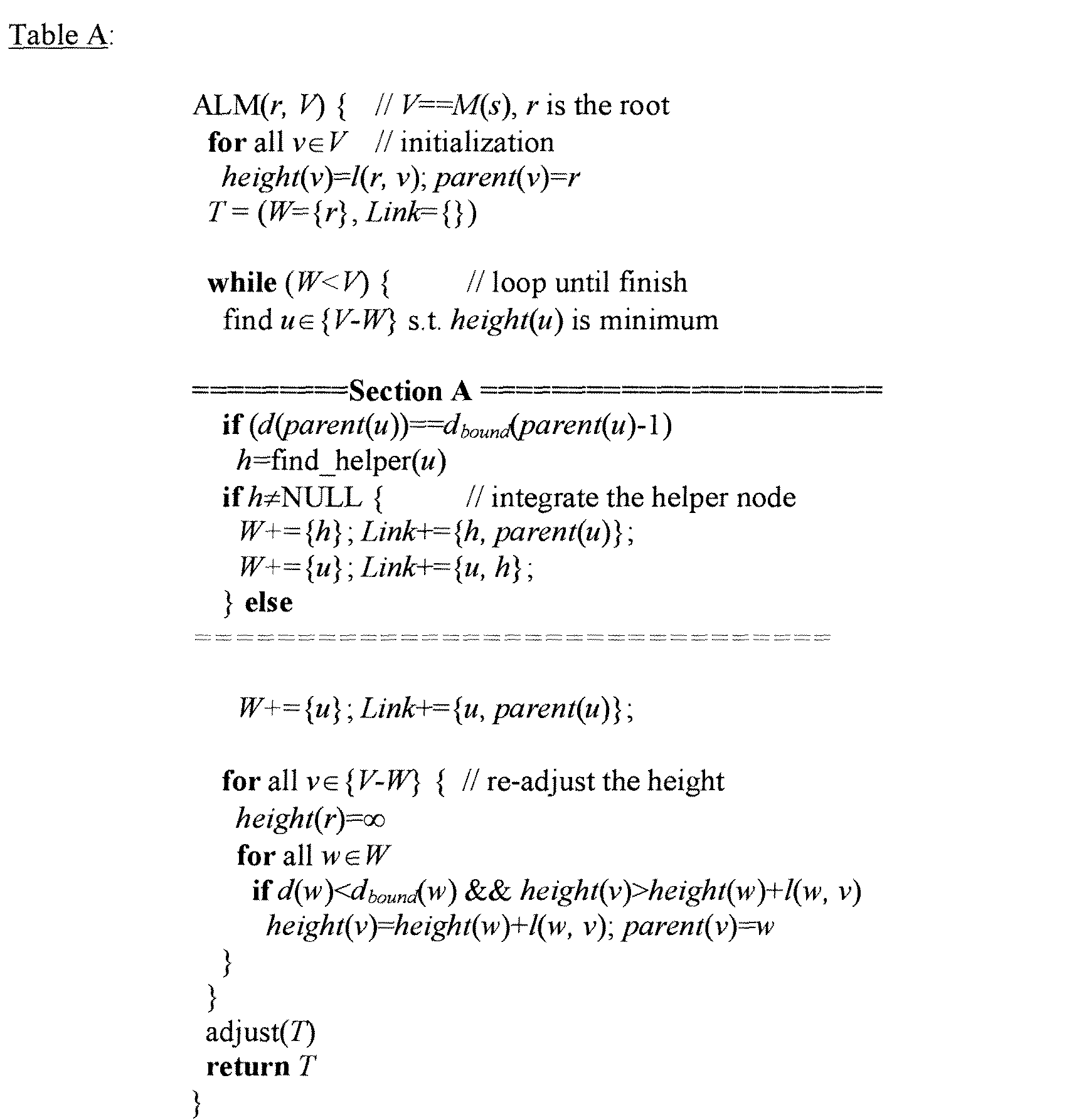
- the general mechanism is described by the pseudo-code in the box labeled "Section A" in the Table A, below: Let u be the node that the AMCast algorithm is about to add to the solution and parent ( u ) be its parent. When parent ( u ) 's free degree is reduced to one, the search is triggered for an additional node h. If such h exists in the resource pool, then h becomes u 's parent instead and replaces u to be the child of the original parent ( u ).
- Different versions vary only on the selection criteria of h , but this class of optimization can be referred to as the critical node algorithm. "Critical" here means that, for a particular node, this is the last opportunity to improve upon the original algorithm.
- a first variation of the algorithm is to find an additional node closest to the parent node and with an adequate degree (e.g., '4' can be used).
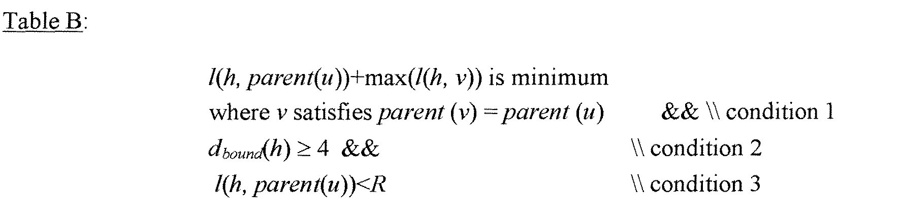
- the following heuristic yields even better results as shown in Table B:
- ⁇ can be one of u 's siblings. The idea here is that since all such ⁇ will potentially be h 's future children, l ( h , parent ( u )) + max ( l(h , ⁇ )) is most likely to affect the potential tree height after h 's joining (condition 1).
- Such a helper node should have adequate degree (condition 2).
- condition 3 we impose a radius R: h must lie within R away from parent ( u ) (condition 3).
- the input parameters necessary to execute the procedure include the network coordinates so that we can calculate latency between an arbitrary pair , as well as the degrees of each node. This is made available by letting each node publish their network coordinates as well as bandwidth constraints in their reports to SOMO as is shown in Figure 12 - which is a visualization of the SOMO report that a scheduler is using.
- each node has a particular load (CPU cycles available), a particular memory capability (RAM, disk space, cache), and also has some network information like where the node is (IP address) and how much available bandwidth the node has.
- Fig. 10a shows the collection of data for use in a SOMO report such as is shown in Fig. 12.
- All the sessions may start and end at random times.
- Each session has an integer valued priority between 1 and 3.
- a priority 1 session is the highest class.
- the number of maximum simultaneous sessions varies from 10 to 60 and each session has non-overlapping member set of size 20.
- all nodes will belong to at least one session. That is, the fraction of original members of active sessions varies from 17% to 100%.
- Counting helper nodes a session typically employ more than the original members. Also, nodes with larger degrees may be involved in more than one session.
- the root of an ALM session is the task manager, which performs the planning and scheduling of the tree topology.
- Each session uses the Leafset+adjustment algorithm to schedule completely on its own, based on system resource information provided by SOMO. For a session with priority L , any resources that are occupied by tasks with lower priorities than L are considered available for its use. Likewise, when an active session loses a resource in its current plan, it will need to perform scheduling again. Each session will also rerun scheduling periodically to examine if a better plan, using recently freed resources, is better than the current one and switch to it if so.
- each node To facilitate SOMO to gather and disseminate resource information so as to aid the planning of each task manager, as before each node publishes its information such as network coordinates in its report to SOMO.
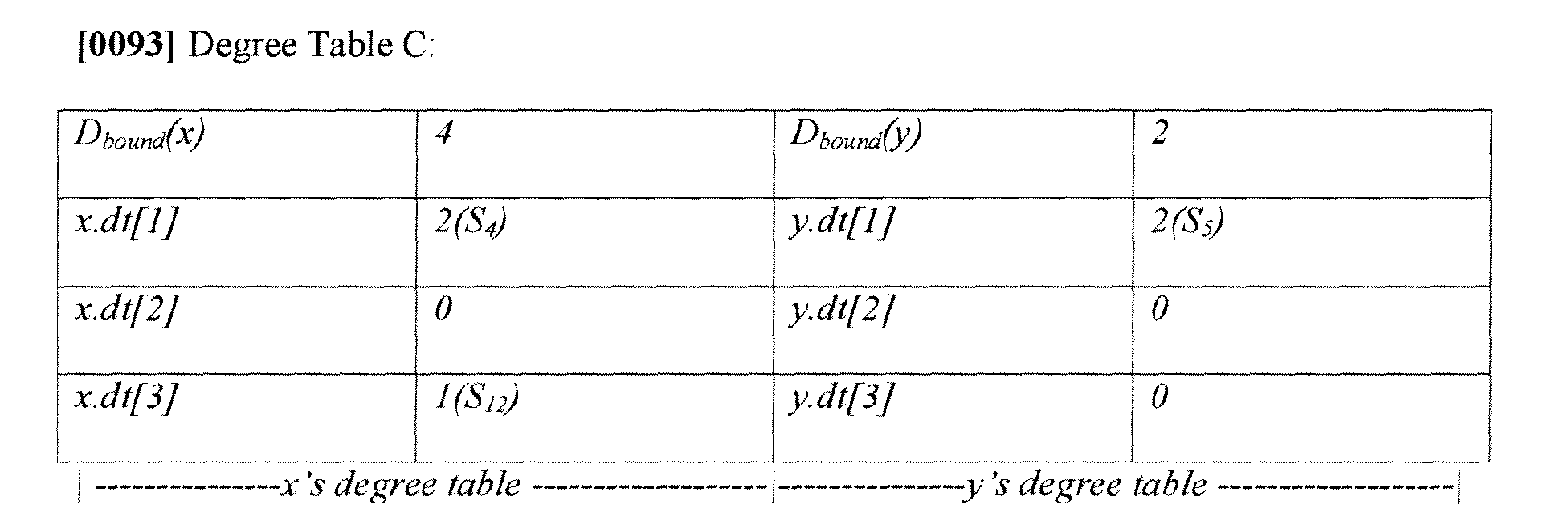
- its degree is broken down into priorities taken by active sessions. This is summarized in the following two examples in Degree Table C:
- Degree Table C the degree tables of two nodes are shown. x's total degree is 4, and is taken by session s4 for 2 degrees, and s12 by another one degree, leaving x with one free degree. y on the other hand, has only two degrees and both of them are taken by session s5.
- the degree tables are updated whenever the scheduling happens that affects a node's degree partition.
- Degree tables as mentioned earlier, are gathered through SOMO and made available for any running task to query.
- Degree Table C shows that it is possible for a machine to partition itself among different streams of ALM sessions so that some things can be done simultaneously by dividing up the bandwidth. As such, Degree Table C shows how many total degrees can be had and how many total capabilities may be had by dividing the capabilities among different jobs so that they can be scheduled as different priority sessions.
- ALM is a favorable application for P2P DHTs.
- a resource pool should be utilized. Given a resource pool, an optimization can be made of a one single ALM session as well as an optimization of multiple simultaneous ALM sessions in a hands-off, market-driven approach. Note, however, that ALM is only one of the applications for P2P resource pool. Nevertheless, for a methodology that is more distributed than centralized matchmaking mechanisms, a two-step approach is advocated: (1) application specific per task scheduling; and (2) combined with market-driven fair competition by coordinating among tasks.
- the data overlay described in Section A, above, is a data structure that can be spread out over multiple machines and possibly over other infrastructure in a P2P system.
- each of the participants in the P2P system can be viewed as implementing a part of the data overlay.
- each participant can store the necessary code and data to create the data overlay and to interact with it.
- This code and data can be stored in the volatile and/or non-volatile memory of each participant (to be described below).
- Fig. 13 shows a high level view of one exemplary P2P participant as a computer 1342.
- This computer 1342 corresponds to a general purpose computer or server type computer and an associated display device 1374.
- the computer 1342 can be implemented using other kinds of computing equipment.
- the computer 1342 can include hand-held or laptop devices, set top boxes, mainframe computers, etc.
- Computer 1342 can be used to implement the processes described herein.
- Computer 1342 includes one or more processors or processing units 1344, a system memory 1346, and a bus 1348 that couples various system components including the system memory 1346 to processors 1344.
- One or more stores in the computer 1342 can be used to store the code and data used to implement part of a data overlay, such as part of the SOMO tree structure.
- the bus 1348 represents one or more of any of several types of bus structures, including a memory bus or memory controller, a peripheral bus, an accelerated graphics port, and a processor or local bus using any of a variety of bus architectures.
- the system memory 1346 includes read only memory (ROM) 1350 and random access memory (RAM) 1352.
- ROM read only memory
- RAM random access memory
- BIOS basic input/output system
- Computer 1342 further includes a hard disk drive 1356 for reading from and writing to a hard disk (not shown), a magnetic disk drive 1358 for reading from and writing to a removable magnetic disk 1360, and an optical disk drive 1362 for reading from or writing to a removable optical disk 1364 such as a CD ROM or other optical media.
- the hard disk drive 1356, magnetic disk drive 1358, and optical disk drive 1362 are connected to the bus 1348 by an SCSI interface 1366 or some other appropriate interface.
- the drives and their associated computer-readable media provide nonvolatile storage of computer-readable instructions, data structures, program modules and other data for computer 1342.
- exemplary environment described herein employs a hard disk, a removable magnetic disk 1360 and a removable optical disk 1364, it should be appreciated by those skilled in the art that other types of computer-readable media which can store data that is accessible by a computer, such as magnetic cassettes, flash memory cards, digital video disks, random access memories (RAMs), read only memories (ROMs), and the like, may also be used in the exemplary operating environment.
- RAMs random access memories
- ROMs read only memories
- a number of program modules may be stored on the hard disk 1356, magnetic disk 1360, optical disk 1364, ROM 1350, or RAM 1352, including an operating system 1370, one or more application programs 1372 (such as the Web request trace application 140), cache/other modules 1374, and program data 1376.
- the operating system 1370 can include a Web request event tracing tool as described herein (such as the trace infrastructure 144).
- a user may enter commands and information into computer 1342 through input devices such as a keyboard 1378 and a pointing device 1380. Other input devices (not shown) may include a microphone, joystick, game pad, satellite dish, scanner, or the like. These and other input devices are connected to the processing unit 1344 through an interface 1382 that is coupled to the bus 1348.
- a monitor 1384 or other type of display device is also connected to the bus 1348 via an interface, such as a video adapter 1386.
- personal computers typically include other peripheral output devices (not shown) such as speakers and printers.
- Computer 1342 commonly operates in a networked environment using logical connections to one or more remote computers, such as a remote computer 1388.
- the remote computer 1388 may be a personal computer, another server, a router, a network PC, a peer device or other common network node, and typically includes many or all of the elements described above relative to computer 1342.
- the logical connections depicted in Fig. 13 include a local area network (LAN) 1390 and a wide area network (WAN) 1392.
- LAN local area network
- WAN wide area network
- computer 1342 When used in a LAN networking environment, computer 1342 is connected to the local network through a network interface or adapter 1394. When used in a WAN networking environment, computer 1342 typically includes a modem 1396 or other means for establishing communications over the wide area network 1392, such as the Internet.
- the modem 1396 which may be internal or external, is connected to the bus 1348 via a serial port interface 1368.
- program modules depicted relative to the personal computer 1342, or portions thereof may be stored in the remote memory storage device. It will be appreciated that the network connections shown are exemplary and other means of establishing a communications link between the computers may be used.
- the data processors of computer 1342 are programmed by means of instructions stored at different times in the various computer-readable storage media of the computer.
- Programs and operating systems are typically distributed, for example, on floppy disks or CD-ROMs. From there, they are installed or loaded into the secondary memory of a computer. At execution, they are loaded at least partially into the computer's primary electronic memory.
- the invention described herein includes these and other various types of computer-readable storage media when such media contain instructions or programs for implementing the blocks described below in conjunction with a microprocessor or other data processor.
- the invention also includes the computer itself when programmed according to the methods and techniques described herein.
- the program code can be stored in one or more computer readable memory devices.
- the illustrated separation of logic and modules into distinct units may reflect an actual physical grouping and allocation of such software and/or hardware, or can correspond to a conceptual allocation of different tasks performed by a single software program and/or hardware unit.
- the illustrated logic and modules can be located at a single site (e.g., as implemented by a single processing device), or can be distributed over plural locations.
- P2P DHT To create a P2P resource pool, the self-organizing capability of P2P DHT is combined with a self-scaling, hierarchical in-system monitoring infrastructure. To achieve self-scaling and robustness, this infrastructure must be a logical hierarchy established in the virtual space created by DHT, and then mapped onto participants. It has been described herein how SOMO combined with DHT effectively creates a resource pool.
- the power of the resource pool can be utilized to take advantage of the on-time and accurate newscast via SOMO, install an application-specific scheduler per each task and then take a hands-off, market-driven approach to coordinate among tasks with fair competition.
- Implementations were described for building a data structure on top of a DHT in a P2P system.
- a specific hierarchical tree structure was specifically described for disseminating information into the P2P system and for collecting information from the P2P system.
- case A or case B a number of examples will be presented in this disclosure in the alternative (e.g., case A or case B).
- this disclosure encompasses those cases which combine alternatives in a single implementation (e.g., case A and case B), even though this disclosure may not expressly mention these conjunctive cases in every instance.
Abstract
Description

This value will be piggybacked in the next heartbeat to x. Likewise, y does the same probing as x. After x collects enough measured bandwidths from its leafset members, it can now estimate its own bottleneck bandwidth as above.
Any of the functions described herein can be implemented using software, firmware (e.g., fixed logic circuitry), manual processing, or a combination of these implementations. The term "logic" or "module" as used herein generally represents software, firmware, or a combination of software and firmware. For instance, in the case of a software implementation, the term "logic" or "module" represents program code that performs specified tasks when executed on a processing device or devices (e.g., CPU or CPUs). The program code can be stored in one or more computer readable memory devices. The illustrated separation of logic and modules into distinct units may reflect an actual physical grouping and allocation of such software and/or hardware, or can correspond to a conceptual allocation of different tasks performed by a single software program and/or hardware unit. The illustrated logic and modules can be located at a single site (e.g., as implemented by a single processing device), or can be distributed over plural locations.
Claims (42)
- A method comprising:building a data overlay as a data structure on top of a logical space included in a distributed hash table (DHT) for a peer-to-peer system; wherein the logical space includes a plurality of DHT nodes having an associated plurality of DHT zones;building, in the data overlay, a topology of a tree having a plurality of levels each including one or more tree nodes associated with respective said DHT nodes, wherein:the first level of the tree includes a single tree node having a single tree node zone corresponding to the entire span of the logical space of the DHT and being logically divided into a plurality of said tree node zones respectively corresponding to:the tree nodes at each level of the tree; andparts of the logical space of the DHT;each said tree node includes a key member which identifies a key associated with its respective tree node zone.mapping a plurality of machines to the logical space of the DHT, wherein:each machine corresponds to one or more of more of the tree node zones;each machine selects as its representative node, from the one or more tree node zones corresponding thereto, the tree node corresponding to the largest size tree node zone; andeach said representative node selects as its parent node another said representative node that is the representative node for an adjacent said tree node zone that has a larger size.
- The method as defined in claim 1, further comprising:gathering metadata at each said machine;sending the metadata gathered at said machine to the corresponding representative node;gathering the metadata received by each said representative node; and sending the metadata gathered by each said representative node to the corresponding parent nade; andgathering metadata received at the single tree node at the first level of the tree.
- The method as defined in Claim 2, further comprising:processing the data gathered at the single tree node at the first level of the tree; andsending the processed data from the single tree node at the first level of the tree to each said machine via the respective parent and representative nodes.
- The method as defined in Claim 3, wherein:the metadata comprises information regarding the operation of each said machine; andthe processed data comprises instructions that can govern the operation of each said machine.
- The method as defined in Claim 1, wherein:the single tree node zone that corresponds to the entire span of the logical space of the DHT is evenly divided into k tree node zones;k is the number of tree nodes at the first level of the tree; andthe j-th tree node at level i of the tree has a tree node zone having:a size of [j/ki, (j+1)/ki]; anda key of(2j+1)/2ki; where (0<=j<2i).
- The method as defined in Claim 5, wherein:each said key has a value that is a function of coordinates that identify the center of the respective tree node zone;the i-th level of the tree contains ki tree nodes; andthe tree node zone of each tree node has a size of 1/ki.
- The method as defined in Claim 1, further comprising computing, for each said machine, the respective keys of the respective representative and parent nodes for the machine.
- The method as defined in Claim 7, wherein the computing the respective keys further comprises obtaining information, with the machine, using a look up in the DHT, wherein the machine uses the information with the key of the corresponding said representative node to establish communication with the machine corresponding to the representative node.
- The method as defined in Claim 1, further comprising:receiving, at each said machine, a heartbeat transmission from each said machine in an adjacent said tree node zone; andwhen any said heartbeat transmission is not timely received, accounting for the absence of the corresponding said machine in the adjacent said tree node zone by:repeating the providing of the DHT;repeating the building of the data overlay as the data structure on top of the logical space of the DHT;repeating the building of the multilevel tree in the rebuilt data overlay; andrepeating the mapping of the plurality of machines to the logical space of the DHT.
- The method as defined in Claim 1, wherein each said representative node and each said parent node is selected as an optimization function of availability of resources.
- The method as defined in Claim 10, wherein the optimization function is based upon criteria selected from the group consisting of network coordinates, bandwidth bottleneck, maximal latency, and variance of latencies, whereby the most resource hungry task is performed by the most resource available machines in the peer-to-peer system.
- The method as defined in claim 1, wherein:the DHT governs the insertion and retrieval of objects into and from the peer-to-peer system; andthe logical space includes a plurality of DHT nodes having an associated plurality of DHT zones; andthe data overlay of the DHT is built by:associating objects in the data structure with the DHT nodes; andestablishing links between the objects in the data structure.
- The method according to claim 12, wherein each link includes:a first field that provides a hardwired pointer that points from a first object to a second object; anda second field that provides a soft-state pointer that points from the first object to a DHT node which hosts the second object.
- The method according to claim 12, wherein the building of the data overlay makes use of:a first primitive for setting a reference that establishes a pointer to an object in the DHT;a second primitive for returning an object referenced by a pointer; anda third primitive for deleting an object referenced by a pointer.
- The method according to claim 1, wherein each tree node in the data overlay includes an operation member which defines an operation that is to be performed on data that is passed through the tree node.
- The method according to claim 1, wherein each tree node in the data overlay includes a report member which defines a report type that is to be generated using the tree node.
- The method according to claim 1, wherein:the first level of the tree includes the tree node that is a root node for the tree; andthe root node corresponds to the tree node zone that corresponds to the entire span of the logical space of the DHT.
- A computer readable store including machine readable instructions for implementing the building of objects in the data overlay according to the method of claim 12.
- A computer readable store having stored thereon a data overlay produced according to the method of claim 1.
- A computer readable store having stored thereon a data structure that comprises a data overlay as a data structure on top of a logical space included in a DHT for a peer-to-peer system; wherein:the DHT governs the insertion and retrieval of objects into and from a peer-to-peer system;the logical space includes a plurality of DHT nodes having an associated plurality of DHT zones;the data overlay of the DHT is built by:associating objects in the data structure with the DHT nodes; andestablishing links between the objects in the data structure;the data overlay has a topology of a tree that includes a plurality of levels;the tree includes a plurality of tree nodes associated with respective said DHT nodes; the tree nodes include a root node having a tree node zone corresponding to the logical space of the DHT;the tree node zone of the root node is logically divided into a plurality of tree node zones respectively corresponding to:the number of tree nodes at each level of the tree; anda part of the logical space of the distributed hash table;each said tree node includes a key member which identifies a key associated with its respective tree node zone;the logical space of the DHT is mapped to a plurality of machines;each machine corresponds to one or more of more of the tree node zones;each machine selects as its representative node, from the one or more tree node zones corresponding thereto, the tree node corresponding to the largest size tree node zone; andeach said representative node selects as its parent node another said representative node that is the representative node for an adjacent said tree node zone that has a larger size.
- The computer readable store as defined in Claim 20, wherein:the tree node zone of the root node is evenly divided into k tree node zones, where k is the number of tree nodes at the first level of the tree; andthe j-th tree node at level i of the tree has a tree node zone having:a size of [j/ki, (j+1)/ki]; anda key of (2j+1)/2ki; where (0<=j<2i).
- The computer readable store as defined in claim 21, wherein:each said key has a value that is a function of coordinates that identify the center of the respective tree node zone;the i-th level of the tree contains ki tree nodes; andthe tree node zone of each tree node has a size of 1/ki.
- The computer readable store as defined in Claim 20, wherein:the DHT governs the insertion and retrieval of objects into and from the peer-to-peer system;the logical space includes a plurality of DHT nodes having an associated plurality of DHT zones; andthe data overlay of the DHT:has objects in the data structure associated with the DHT nodes; andhas links established between the objects in the data structure.
- The computer readable store as defined in Claim 20, wherein each link includes:a first field that provides a hardwired pointer that points from a first object to a second object; anda second field that provides a soft-state pointer that points from the first object to a DHT node which hosts the second object.
- The computer readable store as defined in Claim 20, wherein:a first primitive sets a reference that establishes a pointer to an object in the DHT;a second primitive returns an object referenced by a pointer; anda third primitive deletes an object referenced by a pointer.
- The computer readable store as defined in Claim 20, wherein each tree node in the data overlay includes an operation member which defines an operation that can be performed on data that is passed through the tree node.
- The computer readable store as defined in Claim 20, wherein each tree node in the data overlay includes a report member which defines a report type that is to be generated using the tree node.
- The computer readable store as defined in Claim 20, wherein:the first level of the tree includes the tree node that is a root node for the tree; andthe root node corresponds to the tree node zone that corresponds to the entire span of the logical space of the DHT.
- A peer-to-peer system including a plurality of machines interacting in peer-to-peer fashion, comprising:a logical space of a DHT that includes a plurality of DHT nodes having a plurality of associated DHT zones, wherein the DHT governs the insertion and retrieval of objects into and from the peer-to-peer system;a data overlay as a data structure on top of the logical space of the DHT, wherein:the data overlay of the DHT:has objects in the data structure associated with the DHT nodes; andhas links established between the objects in the data structure;the data overlay has a topology of a tree that includes a plurality of levels and includes a plurality of tree nodes associated with respective said DHT nodes; the tree nodes include a root node having a tree node zone corresponding to the logical space of the DHT;the tree node zone of the root node is logically divided into a plurality of tree node zones respectively corresponding to:the number of tree nodes at each level of the tree; anda part of the logical space of the distributed hash table;each said tree node includes a key member which identifies a key associated with its respective tree node zone;the logical space of the DHT is mapped to a plurality of machines;each machine corresponds to one or more of more of the tree node zones;each machine selects as its representative node, from the one or more tree node zones corresponding thereto, the tree node corresponding to the largest size tree node zone; andeach said representative node selects as its parent node another said representative node that is the representative node for an adjacent said tree node zone that has a larger size.
- The system according to claim 29, further comprising routing logic configured to route data through the data overlay by passing the data through the tree nodes.
- The system according to claim 30, wherein the routing logic is configured to route the data through the data overlay by gathering data from DHT nodes and passing the data up through the tree nodes to the root node of the tree.
- The system according to claim 30, wherein the routing logic is configured to route data through the data overlay by disseminating data from the root node of the tree, through the tree nodes, to the DHT nodes.
- An apparatus for building a peer-to-peer system, the apparatus comprising:means for building a data overlay as a data structure on top of a logical space included in a distributed hash table (DHT) for a peer-to-peer system; wherein:the DHT governs the insertion and retrieval of objects into and from a peer-to-peer system;the logical space includes a plurality of DHT nodes having an associated plurality of DHT zones; andthe data overlay of the DHT is built by:associating objects in the data structure with the DHT nodes; andestablishing links between the objects in the data structure;means for building a topology of a tree in the data overlay, the tree having a plurality of levels and including a plurality of tree nodes associated with respective said DHT nodes, wherein:the tree nodes include a root node having a tree node zone corresponding to the logical space of the DHT;the tree node zone of the root node is logically divided into a plurality of tree node zones respectively corresponding to:the number of tree nodes at each level of the tree; anda part of the logical space of the distributed hash table;each said tree node includes a key member which identifies a key associated with its respective tree node zone;means for mapping a plurality of machines to the logical space of the DHT, wherein each machine corresponds to one or more of more of the tree node zones;means for selecting as its representative node, from the one or more tree node zones corresponding to a respective said machine, the tree node corresponding to the largest size tree node zone; andmeans for selecting for each said representative node as its parent node another said representative node that is the representative node for an adjacent said tree node zone that has a larger size.
- The apparatus as defined in claim 33, further comprising:means for gathering metadata at each said machine;means for sending the metadata gathered at said machine to the corresponding representative node;means for gathering the metadata received by each said representative node; and means for sending the metadata gathered by each said representative node to the corresponding parent node; andmeans for gathering metadata received at the single tree node at the first level of the tree.
- The apparatus as defined in claim 34, further comprising:means for processing the data gathered at the single tree node at the first level of the tree; andmeans for sending the processed data from the single tree node at the first level of the tree to each said machine via the respective parent and representative nodes.
- The apparatus as defined in Claim 35, wherein:the metadata comprises information regarding the operation of each said machine; andthe processed data comprises instructions that can govern the operation of each said machine.
- The apparatus as defined in claim 33, further comprising:means for receiving at a machine a heartbeat transmission from each said machine in an adjacent said tree node zone; andmeans, when any said heartbeat transmission is not timely received, for accounting for the absence of the corresponding said machine in the adjacent said tree node zone by:repeating the providing of the DHT;repeating the building of the data overlay as the data structure on top of the logical space of the DHT; andrepeating the building of the multilevel tree in the rebuilt data overlay.
- The apparatus as defined in claim 37, wherein:the means for accounting further comprises means for repeating the mapping of the plurality of machines to the logical space of the DHT; andthe apparatus further comprises means for selecting each said representative node and each said parent node as an optimization function of availability of resources of the corresponding machines.
- The apparatus as defined in claim 38, wherein the optimization function is based upon criteria selected from the group consisting of network coordinates, bandwidth bottleneck, maximal latency, and variance of latencies, whereby the most resource hungry task is performed by the most resource available machines in the peer-to-peer system.
- The apparatus as defined in claim 33, further comprising means for routing data through the data overlay by passing the data through the tree nodes.
- The apparatus as defined in claim 40, wherein the routing means includes means for routing the data through the data overlay by gathering data from DHT nodes and passing the data up through the tree nodes to the root node of the tree.
- The apparatus as defined in claim 40, wherein the routing means includes means for routing data through the data overlay by disseminating data from the root node of the tree, through the tree nodes, to the DHT nodes.
Applications Claiming Priority (2)
| Application Number | Priority Date | Filing Date | Title |
|---|---|---|---|
| US826674 | 2004-04-16 | ||
| US10/826,674 US7418454B2 (en) | 2004-04-16 | 2004-04-16 | Data overlay, self-organized metadata overlay, and application level multicasting |
Publications (3)
| Publication Number | Publication Date |
|---|---|
| EP1587282A2 true EP1587282A2 (en) | 2005-10-19 |
| EP1587282A3 EP1587282A3 (en) | 2006-05-24 |
| EP1587282B1 EP1587282B1 (en) | 2007-08-08 |
Family
ID=34939303
Family Applications (1)
| Application Number | Title | Priority Date | Filing Date |
|---|---|---|---|
| EP05102991A Not-in-force EP1587282B1 (en) | 2004-04-16 | 2005-04-15 | Data overlay, self-organized metadata overlay, and application level multicasting |
Country Status (7)
| Country | Link |
|---|---|
| US (1) | US7418454B2 (en) |
| EP (1) | EP1587282B1 (en) |
| JP (1) | JP4750457B2 (en) |
| KR (1) | KR101120847B1 (en) |
| CN (1) | CN1708026B (en) |
| AT (1) | ATE369693T1 (en) |
| DE (1) | DE602005001883T2 (en) |
Cited By (17)
| Publication number | Priority date | Publication date | Assignee | Title |
|---|---|---|---|---|
| WO2007149338A2 (en) * | 2006-06-16 | 2007-12-27 | Lucent Technologies Inc. | Methods, devices and architectures for establishing peer-to -peer sessions |
| GB2446200A (en) * | 2006-12-01 | 2008-08-06 | David Irvine | Encryption system for peer-to-peer networks which relies on hash based self-encryption and mapping |
| WO2008135304A1 (en) * | 2007-05-04 | 2008-11-13 | Telefonaktiebolaget Lm Ericsson (Publ) | Mobile device file sharing method and apparatus |
| EP2034665A1 (en) * | 2006-06-26 | 2009-03-11 | Huawei Technologies Co., Ltd. | Domain manager system, method and device for acquiring neighbor domain manager and updating domain manager |
| WO2010108265A1 (en) * | 2009-03-26 | 2010-09-30 | Terascale Supercomputing Inc. | Network topology comprising a hierarchical structure of nodes grouped into units |
| WO2011039555A1 (en) * | 2009-10-01 | 2011-04-07 | Telefonaktiebolaget L M Ericsson (Publ) | Location aware mass information distribution system and method |
| US7957385B2 (en) | 2009-03-26 | 2011-06-07 | Terascale Supercomputing Inc. | Method and apparatus for packet routing |
| CN101193032B (en) * | 2006-11-29 | 2012-03-21 | 曲锐 | Data processing method and network based on distributed hash table |
| US8255736B2 (en) | 2007-02-22 | 2012-08-28 | Telefonaktiebolaget Lm Ericsson (Publ) | Consistent and fault tolerant distributed hash table (DHT) overlay network |
| CN101656618B (en) * | 2009-09-11 | 2012-09-05 | 中兴通讯股份有限公司 | Multimedia message broadcasting method and system based on structural Peer-to-Peer Network (PPN) |
| CN101465796B (en) * | 2007-12-19 | 2012-10-31 | 中国移动通信集团公司 | Method, device and system for collecting and distributing P2P system metadata |
| US8312065B2 (en) | 2006-04-11 | 2012-11-13 | Brother Kogyo Kabushiki Kaisha | Tree-type broadcast system, reconnection process method, node device, node process program, server device, and server process program |
| WO2013102253A1 (en) * | 2012-01-04 | 2013-07-11 | Hongbing Fan | System and method for providing p2p based reconfigurable computing and structured data distribution |
| US8654678B2 (en) | 2006-04-12 | 2014-02-18 | Brother Kogyo Kabushiki Kaisha | Node device, recording medium where storage control program is recorded, and information storing method |
| CN104272286A (en) * | 2012-07-20 | 2015-01-07 | 惠普发展公司,有限责任合伙企业 | Policy-based scaling of network resources |
| WO2017201027A3 (en) * | 2016-05-16 | 2017-12-28 | Interdigital Patent Holdings, Inc. | Enhancements for ieee 802.11ah relays |
| CN112216375A (en) * | 2020-09-03 | 2021-01-12 | 南京信息工程大学 | Method for autonomously constructing medical monitoring system |
Families Citing this family (77)
| Publication number | Priority date | Publication date | Assignee | Title |
|---|---|---|---|---|
| US8316088B2 (en) * | 2004-07-06 | 2012-11-20 | Nokia Corporation | Peer-to-peer engine for object sharing in communication devices |
| JP4506387B2 (en) * | 2004-09-30 | 2010-07-21 | ブラザー工業株式会社 | Information communication system, node device, overlay network forming method, etc. |
| FR2878673B1 (en) * | 2004-11-26 | 2007-02-09 | Univ Picardie Jules Verne Etab | PERENNE DISTRIBUTED BACKUP SYSTEM AND METHOD |
| US20080130516A1 (en) * | 2004-12-21 | 2008-06-05 | Electronics And Telecommunications Research Institute | P2p Overplay Network Construction Method and Apparatus |
| US7428220B1 (en) * | 2005-02-10 | 2008-09-23 | Sun Microsystems, Inc. | Method and apparatus for data aggregation in a distributed system |
| US7895270B2 (en) * | 2005-04-21 | 2011-02-22 | Microsoft Corporation | Transport abstraction for multiparty replication |
| US20070011171A1 (en) * | 2005-07-08 | 2007-01-11 | Nurminen Jukka K | System and method for operation control functionality |
| JP4544072B2 (en) * | 2005-07-20 | 2010-09-15 | ブラザー工業株式会社 | Node device, computer program, information distribution system, and network participation method |
| US7489689B2 (en) * | 2005-10-26 | 2009-02-10 | Cisco Technology, Inc. | Method, system and apparatus for scheduling a large pool of resources |
| JP2007235243A (en) * | 2006-02-27 | 2007-09-13 | Brother Ind Ltd | Information communication system, information collection method, node apparatus, and node processing program |
| JP4692355B2 (en) * | 2006-03-30 | 2011-06-01 | ブラザー工業株式会社 | Information communication system, information communication method, node device included in information communication system, and information processing program |
| US7516116B2 (en) * | 2006-04-07 | 2009-04-07 | Microsoft Corporation | Range and cover queries in overlay networks |
| JP2007280303A (en) * | 2006-04-11 | 2007-10-25 | Brother Ind Ltd | Information communication system, content catalogue information distribution method and node device |
| GB0607294D0 (en) * | 2006-04-11 | 2006-05-24 | Nokia Corp | A node |
| JP4539603B2 (en) * | 2006-04-13 | 2010-09-08 | ブラザー工業株式会社 | Information communication system, information communication method, node device included in information communication system, and information processing program |
| TW200741493A (en) * | 2006-04-18 | 2007-11-01 | Benq Corp | Systems and methods for discovering frequently accessed subtrees |
| JP4670726B2 (en) * | 2006-04-28 | 2011-04-13 | ブラザー工業株式会社 | NODE DEVICE, INFORMATION PROCESSING METHOD, AND NODE DEVICE PROGRAM |
| US7523340B2 (en) | 2006-05-31 | 2009-04-21 | Microsoft Corporation | Support self-heal tool |
| US8375141B2 (en) * | 2006-09-29 | 2013-02-12 | Microsoft Corporation | Infrastructure to disseminate queries and provide query results |
| US20100095009A1 (en) * | 2006-10-02 | 2010-04-15 | Nokia Corporation | Method, System, and Devices for Network Sharing or Searching Of Resources |
| US7684352B2 (en) * | 2006-11-02 | 2010-03-23 | Nortel Networks Ltd | Distributed storage of routing information in a link state protocol controlled network |
| CN101005606B (en) * | 2006-12-31 | 2012-07-04 | 华为技术有限公司 | Method and device for reducing medium playing delay |
| US8018453B2 (en) * | 2007-02-09 | 2011-09-13 | International Business Machines Corporation | Deferred acceleration data structure optimization for improved performance |
| US8140625B2 (en) * | 2007-02-20 | 2012-03-20 | Nec Laboratories America, Inc. | Method for operating a fixed prefix peer to peer network |
| US8693392B2 (en) * | 2007-02-21 | 2014-04-08 | Avaya Canada Corp. | Peer-to-peer communication system and method |
| US7630370B2 (en) * | 2007-02-28 | 2009-12-08 | Sharp Laboratories Of America, Inc. | Overlay join latency reduction using preferred peer list |
| US20110047272A1 (en) * | 2007-03-09 | 2011-02-24 | Anne-Marie Bosneag | Dissemination of Network Management Tasks in a Distributed Communication Network |
| US20080225780A1 (en) * | 2007-03-13 | 2008-09-18 | Nortel Networks Limited | Use of distributed hashtables for wireless access mobility management |
| JP4172522B1 (en) * | 2007-04-12 | 2008-10-29 | ヤマハ株式会社 | Multicast distribution system and multicast distribution method |
| CN101291321B (en) * | 2007-04-19 | 2012-10-03 | 华为技术有限公司 | Method and system for publishing content, method and system for searching content |
| JP4389964B2 (en) * | 2007-05-15 | 2009-12-24 | ソニー株式会社 | Information processing apparatus, information processing method, and program |
| CN101350807B (en) * | 2007-07-20 | 2012-04-04 | 华为技术有限公司 | Multiple address space mobile network architecture, method for host information registration and data transmission |
| US7970916B2 (en) * | 2007-07-25 | 2011-06-28 | Cisco Technology, Inc. | Register clustering in a sip-based network |
| CN101399746B (en) * | 2007-09-26 | 2011-03-16 | 华为技术有限公司 | Packet routing method, system, device and method, system for selecting backup resource |
| US8582469B2 (en) * | 2007-11-14 | 2013-11-12 | Cisco Technology, Inc. | Peer-to-peer network including routing protocol enhancement |
| JP4863973B2 (en) * | 2007-11-26 | 2012-01-25 | 日本電信電話株式会社 | Overlay multicast distribution network configuration method, system and program |
| JP5029373B2 (en) * | 2008-01-11 | 2012-09-19 | 日本電気株式会社 | Node, route control method, and route control program |
| JP5151511B2 (en) * | 2008-01-30 | 2013-02-27 | ソニー株式会社 | Search service providing system and search service providing method |
| JP5058135B2 (en) * | 2008-02-08 | 2012-10-24 | パナソニック株式会社 | Terminal device |
| US20090213754A1 (en) * | 2008-02-26 | 2009-08-27 | Roie Melamed | Device, System, and Method of Group Communication |
| US8610673B2 (en) | 2008-12-03 | 2013-12-17 | Microsoft Corporation | Manipulation of list on a multi-touch display |
| US8264988B2 (en) * | 2009-01-30 | 2012-09-11 | Nec Laboratories America, Inc. | Method for inferring physical network topology from end-to-end measurement |
| US8078825B2 (en) * | 2009-03-11 | 2011-12-13 | Oracle America, Inc. | Composite hash and list partitioning of database tables |
| US8019862B2 (en) | 2009-03-17 | 2011-09-13 | Microsoft Corporation | Collaborative speed determination in distributed systems |
| CN102077508B (en) * | 2009-03-18 | 2013-06-19 | 松下电器产业株式会社 | Multicast communication method and apparatus for receiving and forwarding data via a network among a plurality of nodes |
| CN101534309B (en) | 2009-04-14 | 2013-03-13 | 华为技术有限公司 | A node registration method, a routing update method, a communication system and the relevant equipment |
| JP4818396B2 (en) * | 2009-05-22 | 2011-11-16 | 株式会社東芝 | Overlay network system and object registration method in the same system |
| CN101938509B (en) * | 2009-06-29 | 2015-11-25 | 日电(中国)有限公司 | For P2P network provides server, the method and system of nodal information |
| CN101635645B (en) * | 2009-08-28 | 2012-01-11 | 中兴通讯股份有限公司 | Method and device for managing network topology |
| US7716179B1 (en) * | 2009-10-29 | 2010-05-11 | Wowd, Inc. | DHT-based distributed file system for simultaneous use by millions of frequently disconnected, world-wide users |
| US9922331B2 (en) * | 2009-11-04 | 2018-03-20 | Blue Kai, Inc. | Filter for user information based on enablement of persistent identification |
| DE102010006991A1 (en) * | 2010-02-05 | 2011-08-11 | Siemens Aktiengesellschaft, 80333 | Method for managing information i.e. medical image information of patient for diagnosing diseases in hospital, involves retrieving metal data assigned to key data from devices, and storing image data assigned to meta data in devices |
| US9767475B2 (en) * | 2010-08-20 | 2017-09-19 | Blue Kai, Inc. | Real time audience forecasting |
| CN103098015B (en) * | 2010-09-30 | 2015-11-25 | 日本电气株式会社 | Storage system |
| KR20120071576A (en) * | 2010-12-23 | 2012-07-03 | 한국전자통신연구원 | Method, device and system for real-time publish subscribe discovery based on distributed hash table |
| EP2477377A1 (en) * | 2011-01-14 | 2012-07-18 | Alcatel Lucent | Peer node and method for improved peer node selection |
| US9317221B2 (en) * | 2011-03-16 | 2016-04-19 | Nec Corporation | Distributed storage system and distributed storage method |
| CN102185935B (en) * | 2011-04-27 | 2013-07-31 | 北京交通大学 | Resource-oriented hierarchical name resolution system |
| JP6094487B2 (en) * | 2011-09-27 | 2017-03-15 | 日本電気株式会社 | Information system, management apparatus, data processing method, data structure, program, and recording medium |
| WO2013046667A1 (en) * | 2011-09-27 | 2013-04-04 | 日本電気株式会社 | Information system, program and method for managing same, data processing method and program, and data structure |
| JPWO2013132779A1 (en) * | 2012-03-09 | 2015-07-30 | 日本電気株式会社 | Object placement apparatus and method, computer program |
| JP5818263B2 (en) * | 2012-05-10 | 2015-11-18 | 日本電信電話株式会社 | Data distributed management system, apparatus, method and program |
| US10740797B2 (en) * | 2012-07-30 | 2020-08-11 | Oath Inc. | Systems and methods for implementing a mobile application based online advertising system |
| JP6182861B2 (en) * | 2012-12-28 | 2017-08-23 | 富士通株式会社 | Information processing apparatus, information processing terminal, information search program, and information search method |
| CN104063420B (en) * | 2014-03-25 | 2015-08-26 | 深圳市挪亚物联信息技术有限公司 | A kind of method and system unified Dynamic Data Model and realize |
| US9805392B2 (en) * | 2014-07-02 | 2017-10-31 | Oracle International Corporation | Simulating online user activity to generate an advertising campaign target audience list |
| CN105488088B (en) * | 2014-12-31 | 2019-05-07 | 哈尔滨安天科技股份有限公司 | Two-dimensional network angular distribution layout method based on tree structure |
| US10652322B2 (en) * | 2015-03-09 | 2020-05-12 | International Business Machines Corporation | Scalable parallel messaging process |
| EP3304303B1 (en) * | 2015-06-03 | 2021-06-09 | Telefonaktiebolaget LM Ericsson (PUBL) | Allocating or announcing availability of a software container |
| CN105573836B (en) * | 2016-02-23 | 2018-12-28 | 中国农业银行股份有限公司 | Data processing method and device |
| SG10201912412PA (en) * | 2016-03-07 | 2020-02-27 | Agency Science Tech & Res | Method of facilitating distributed data search in a federated cloud and system thereof |
| CN107453994A (en) * | 2016-05-30 | 2017-12-08 | 北京信威通信技术股份有限公司 | Data transmission method and device based on DHT networks |
| KR102603069B1 (en) * | 2016-11-19 | 2023-11-15 | 디피니티 스티프텅 | System architecture and data processing methods in system architecture |
| CN109962942B (en) * | 2017-12-22 | 2022-06-07 | 天翼云科技有限公司 | Copy update method and apparatus, and computer-readable storage medium |
| WO2020010270A1 (en) * | 2018-07-04 | 2020-01-09 | Neji, Inc. | Dynamic routing using a distributed hash table |
| CN109274759A (en) * | 2018-10-19 | 2019-01-25 | 杭州和利时自动化有限公司 | Communication means and device between a kind of Distributed Control System and its node |
| CN112187912B (en) * | 2020-09-24 | 2023-12-19 | 宜宾三江电子信息产业有限公司 | Data roaming method and device based on distributed network |
Family Cites Families (5)
| Publication number | Priority date | Publication date | Assignee | Title |
|---|---|---|---|---|
| DE60131900T2 (en) | 2000-10-26 | 2008-12-04 | Flood, James C. jun., Portland | METHOD AND SYSTEM FOR MANAGING DISTRIBUTED CONTENT AND RELATED METADATA |
| US7054867B2 (en) * | 2001-09-18 | 2006-05-30 | Skyris Networks, Inc. | Systems, methods and programming for routing and indexing globally addressable objects and associated business models |
| US7644182B2 (en) * | 2004-03-11 | 2010-01-05 | Hewlett-Packard Development Company, L.P. | Reconfiguring a multicast tree |
| US7730207B2 (en) * | 2004-03-31 | 2010-06-01 | Microsoft Corporation | Routing in peer-to-peer networks |
| US20070079004A1 (en) * | 2005-09-30 | 2007-04-05 | Junichi Tatemura | Method and apparatus for distributed indexing |
-
2004
- 2004-04-16 US US10/826,674 patent/US7418454B2/en not_active Expired - Fee Related
-
2005
- 2005-04-13 CN CN2005100878055A patent/CN1708026B/en not_active Expired - Fee Related
- 2005-04-15 KR KR1020050031660A patent/KR101120847B1/en active IP Right Grant
- 2005-04-15 DE DE602005001883T patent/DE602005001883T2/en active Active
- 2005-04-15 EP EP05102991A patent/EP1587282B1/en not_active Not-in-force
- 2005-04-15 AT AT05102991T patent/ATE369693T1/en not_active IP Right Cessation
- 2005-04-18 JP JP2005119800A patent/JP4750457B2/en not_active Expired - Fee Related
Non-Patent Citations (4)
| Title |
|---|
| DABEK F ET AL: "Building peer-to-peer systems with chord, a distributed lookup service" HOT TOPICS IN OPERATING SYSTEMS, 2001. PROCEEDINGS OF THE EIGHTH WORKSHOP ON 20-22 MAY 2001, PISCATAWAY, NJ, USA,IEEE, 20 May 2001 (2001-05-20), pages 81-86, XP010583087 ISBN: 0-7695-1040-X * |
| MISRA A ET AL: "CLASH: A protocol for internet-scale utility-oriented distributed computing" DISTRIBUTED COMPUTING SYSTEMS, 2004. PROCEEDINGS. 24TH INTERNATIONAL CONFERENCE ON HACHIOJI, TOKYO, JAPAN 24-26 MARCH 2004, PISCATAWAY, NJ, USA,IEEE, 24 March 2004 (2004-03-24), pages 273-281, XP010692674 ISBN: 0-7695-2086-3 * |
| RATNASAMY S ET AL: "A SCALABLE CONTENT-ADDRESSABLE NETWORK" COMPUTER COMMUNICATION REVIEW, ACM, NEW YORK, NY, US, vol. 31, no. 4, October 2001 (2001-10), pages 161-172, XP001115754 ISSN: 0146-4833 * |
| ZHENG ZHANG; SHU-MING SHI; JING ZHU: "SOMO: self-organized metadata overlay for resource management in P2P DHT" SPRINGER VERLAG, BERLIN, [Online] vol. 2735, 2003, pages 172-180, XP002374008 Peer-to-Peer Systems II. Second International Workshop, IPTPS 2003. Retrieved from the Internet: URL:http://www.springerlink.com/media/bd1b m4803j0xrwccaq9x/contributions/t/2/1/p/t21 pmkmpm96dc56k.pdf> [retrieved on 2006-03-23] * |
Cited By (29)
| Publication number | Priority date | Publication date | Assignee | Title |
|---|---|---|---|---|
| US8312065B2 (en) | 2006-04-11 | 2012-11-13 | Brother Kogyo Kabushiki Kaisha | Tree-type broadcast system, reconnection process method, node device, node process program, server device, and server process program |
| US8654678B2 (en) | 2006-04-12 | 2014-02-18 | Brother Kogyo Kabushiki Kaisha | Node device, recording medium where storage control program is recorded, and information storing method |
| WO2007149338A3 (en) * | 2006-06-16 | 2008-02-07 | Lucent Technologies Inc | Methods, devices and architectures for establishing peer-to -peer sessions |
| WO2007149338A2 (en) * | 2006-06-16 | 2007-12-27 | Lucent Technologies Inc. | Methods, devices and architectures for establishing peer-to -peer sessions |
| JP2009540679A (en) * | 2006-06-16 | 2009-11-19 | アルカテル−ルーセント ユーエスエー インコーポレーテッド | Method, apparatus and architecture for establishing a peer-to-peer session |
| US7643459B2 (en) | 2006-06-16 | 2010-01-05 | Alcatel-Lucent Usa Inc. | Methods, devices and architectures for establishing peer-to-peer sessions |
| CN101473630B (en) * | 2006-06-16 | 2013-09-04 | 卢森特技术有限公司 | Methods, devices and architectures for establishing peer-to -peer sessions |
| EP2034665A1 (en) * | 2006-06-26 | 2009-03-11 | Huawei Technologies Co., Ltd. | Domain manager system, method and device for acquiring neighbor domain manager and updating domain manager |
| EP2034665A4 (en) * | 2006-06-26 | 2009-06-10 | Huawei Tech Co Ltd | Domain manager system, method and device for acquiring neighbor domain manager and updating domain manager |
| CN101193032B (en) * | 2006-11-29 | 2012-03-21 | 曲锐 | Data processing method and network based on distributed hash table |
| GB2446200A (en) * | 2006-12-01 | 2008-08-06 | David Irvine | Encryption system for peer-to-peer networks which relies on hash based self-encryption and mapping |
| US8255736B2 (en) | 2007-02-22 | 2012-08-28 | Telefonaktiebolaget Lm Ericsson (Publ) | Consistent and fault tolerant distributed hash table (DHT) overlay network |
| WO2008135304A1 (en) * | 2007-05-04 | 2008-11-13 | Telefonaktiebolaget Lm Ericsson (Publ) | Mobile device file sharing method and apparatus |
| CN101465796B (en) * | 2007-12-19 | 2012-10-31 | 中国移动通信集团公司 | Method, device and system for collecting and distributing P2P system metadata |
| US7957385B2 (en) | 2009-03-26 | 2011-06-07 | Terascale Supercomputing Inc. | Method and apparatus for packet routing |
| US7957400B2 (en) | 2009-03-26 | 2011-06-07 | Terascale Supercomputing Inc. | Hierarchical network topology |
| WO2010108265A1 (en) * | 2009-03-26 | 2010-09-30 | Terascale Supercomputing Inc. | Network topology comprising a hierarchical structure of nodes grouped into units |
| US8457135B2 (en) | 2009-03-26 | 2013-06-04 | Terascale Supercomputing Inc. | Hierarchical network topology |
| CN101656618B (en) * | 2009-09-11 | 2012-09-05 | 中兴通讯股份有限公司 | Multimedia message broadcasting method and system based on structural Peer-to-Peer Network (PPN) |
| WO2011039555A1 (en) * | 2009-10-01 | 2011-04-07 | Telefonaktiebolaget L M Ericsson (Publ) | Location aware mass information distribution system and method |
| US9357001B2 (en) | 2009-10-01 | 2016-05-31 | Telefonaktiebolaget Lm Ericsson (Publ) | Location aware mass information distribution system and method |
| WO2013102253A1 (en) * | 2012-01-04 | 2013-07-11 | Hongbing Fan | System and method for providing p2p based reconfigurable computing and structured data distribution |
| US20150003296A1 (en) * | 2012-01-04 | 2015-01-01 | Hongbing Fan | System and method for providing p2p based reconfigurable computing and structured data distribution |
| CN104272286A (en) * | 2012-07-20 | 2015-01-07 | 惠普发展公司,有限责任合伙企业 | Policy-based scaling of network resources |
| US10057179B2 (en) | 2012-07-20 | 2018-08-21 | Hewlett Packard Enterprise Development Company Lp | Policy based scaling of network resources |
| US10798016B2 (en) | 2012-07-20 | 2020-10-06 | Hewlett Packard Enterprise Development Lp | Policy-based scaling of network resources |
| WO2017201027A3 (en) * | 2016-05-16 | 2017-12-28 | Interdigital Patent Holdings, Inc. | Enhancements for ieee 802.11ah relays |
| CN112216375A (en) * | 2020-09-03 | 2021-01-12 | 南京信息工程大学 | Method for autonomously constructing medical monitoring system |
| CN112216375B (en) * | 2020-09-03 | 2023-05-09 | 南京信息工程大学 | Method for autonomously constructing medical monitoring system |
Also Published As
| Publication number | Publication date |
|---|---|
| JP4750457B2 (en) | 2011-08-17 |
| DE602005001883T2 (en) | 2007-12-20 |
| ATE369693T1 (en) | 2007-08-15 |
| US7418454B2 (en) | 2008-08-26 |
| DE602005001883D1 (en) | 2007-09-20 |
| US20050243740A1 (en) | 2005-11-03 |
| EP1587282B1 (en) | 2007-08-08 |
| CN1708026B (en) | 2011-07-27 |
| KR20060045788A (en) | 2006-05-17 |
| JP2005353039A (en) | 2005-12-22 |
| EP1587282A3 (en) | 2006-05-24 |
| CN1708026A (en) | 2005-12-14 |
| KR101120847B1 (en) | 2012-03-16 |
Similar Documents
| Publication | Publication Date | Title |
|---|---|---|
| EP1587282B1 (en) | Data overlay, self-organized metadata overlay, and application level multicasting | |
| US7313565B2 (en) | Data overlay, self-organized metadata overlay, and associated methods | |
| Mastroianni et al. | A super-peer model for resource discovery services in large-scale grids | |
| US8756253B2 (en) | Two-level structured overlay design for cluster management in a peer-to-peer network | |
| Zarrin et al. | Resource discovery for distributed computing systems: A comprehensive survey | |
| Li et al. | DPTree: A balanced tree based indexing framework for peer-to-peer systems | |
| Doulkeridis et al. | Efficient search based on content similarity over self-organizing P2P networks | |
| Forestiero et al. | So-grid: A self-organizing grid featuring bio-inspired algorithms | |
| Costa et al. | Autonomous resource selection for decentralized utility computing | |
| Graffi et al. | Skyeye. kom: An information management over-overlay for getting the oracle view on structured p2p systems | |
| den Burger et al. | Collective receiver-initiated multicast for grid applications | |
| Forestiero et al. | Antares: An ant-inspired P2P information system for a self-structured grid | |
| Rivière et al. | Compositional gossip: a conceptual architecture for designing gossip-based applications | |
| Meiklejohn et al. | Loquat: A framework for large-scale actor communication on edge networks | |
| Han et al. | A lightweight personal grid using a supernode network | |
| Vasilakos et al. | Decentralized as-soon-as-possible grid scheduling: a feasibility study | |
| van Renesse et al. | Autonomic computing: A system-wide perspective | |
| Gramoli et al. | Slicing distributed systems | |
| Chazapis et al. | Replica-aware, multi-dimensional range queries in distributed hash tables | |
| Blanas et al. | Contention-based performance evaluation of multidimensional range search in peer-to-peer networks | |
| Hefeeda | A framework for cost-effective peer-to-peer content distribution | |
| Yang et al. | Automatic clustering for self-organizing grids | |
| Celaya et al. | YA: Fast and Scalable Discovery of Idle CPUs in a P2P network. | |
| Zhang et al. | P2P resource pool and its application to optimize wide-area application level multicasting | |
| Celaya et al. | Scalable architecture for allocation of idle CPUs in a P2P network |
Legal Events
| Date | Code | Title | Description |
|---|---|---|---|
| PUAI | Public reference made under article 153(3) epc to a published international application that has entered the european phase |
Free format text: ORIGINAL CODE: 0009012 |
|
| AK | Designated contracting states |
Kind code of ref document: A2 Designated state(s): AT BE BG CH CY CZ DE DK EE ES FI FR GB GR HU IE IS IT LI LT LU MC NL PL PT RO SE SI SK TR |
|
| AX | Request for extension of the european patent |
Extension state: AL BA HR LV MK YU |
|
| PUAL | Search report despatched |
Free format text: ORIGINAL CODE: 0009013 |
|
| AK | Designated contracting states |
Kind code of ref document: A3 Designated state(s): AT BE BG CH CY CZ DE DK EE ES FI FR GB GR HU IE IS IT LI LT LU MC NL PL PT RO SE SI SK TR |
|
| AX | Request for extension of the european patent |
Extension state: AL BA HR LV MK YU |
|
| 17P | Request for examination filed |
Effective date: 20061122 |
|
| AKX | Designation fees paid |
Designated state(s): AT BE BG CH CY CZ DE DK EE ES FI FR GB GR HU IE IS IT LI LT LU MC NL PL PT RO SE SI SK TR |
|
| GRAP | Despatch of communication of intention to grant a patent |
Free format text: ORIGINAL CODE: EPIDOSNIGR1 |
|
| GRAS | Grant fee paid |
Free format text: ORIGINAL CODE: EPIDOSNIGR3 |
|
| GRAA | (expected) grant |
Free format text: ORIGINAL CODE: 0009210 |
|
| AK | Designated contracting states |
Kind code of ref document: B1 Designated state(s): AT BE BG CH CY CZ DE DK EE ES FI FR GB GR HU IE IS IT LI LT LU MC NL PL PT RO SE SI SK TR |
|
| RAP1 | Party data changed (applicant data changed or rights of an application transferred) |
Owner name: MICROSOFT CORPORATION |
|
| REG | Reference to a national code |
Ref country code: GB Ref legal event code: FG4D |
|
| REG | Reference to a national code |
Ref country code: CH Ref legal event code: EP |
|
| REG | Reference to a national code |
Ref country code: IE Ref legal event code: FG4D |
|
| REF | Corresponds to: |
Ref document number: 602005001883 Country of ref document: DE Date of ref document: 20070920 Kind code of ref document: P |
|
| PG25 | Lapsed in a contracting state [announced via postgrant information from national office to epo] |
Ref country code: IS Free format text: LAPSE BECAUSE OF FAILURE TO SUBMIT A TRANSLATION OF THE DESCRIPTION OR TO PAY THE FEE WITHIN THE PRESCRIBED TIME-LIMIT Effective date: 20071208 Ref country code: LT Free format text: LAPSE BECAUSE OF FAILURE TO SUBMIT A TRANSLATION OF THE DESCRIPTION OR TO PAY THE FEE WITHIN THE PRESCRIBED TIME-LIMIT Effective date: 20070808 Ref country code: NL Free format text: LAPSE BECAUSE OF FAILURE TO SUBMIT A TRANSLATION OF THE DESCRIPTION OR TO PAY THE FEE WITHIN THE PRESCRIBED TIME-LIMIT Effective date: 20070808 Ref country code: BG Free format text: LAPSE BECAUSE OF FAILURE TO SUBMIT A TRANSLATION OF THE DESCRIPTION OR TO PAY THE FEE WITHIN THE PRESCRIBED TIME-LIMIT Effective date: 20071108 Ref country code: ES Free format text: LAPSE BECAUSE OF FAILURE TO SUBMIT A TRANSLATION OF THE DESCRIPTION OR TO PAY THE FEE WITHIN THE PRESCRIBED TIME-LIMIT Effective date: 20071119 Ref country code: FI Free format text: LAPSE BECAUSE OF FAILURE TO SUBMIT A TRANSLATION OF THE DESCRIPTION OR TO PAY THE FEE WITHIN THE PRESCRIBED TIME-LIMIT Effective date: 20070808 |
|
| NLV1 | Nl: lapsed or annulled due to failure to fulfill the requirements of art. 29p and 29m of the patents act | ||
| REG | Reference to a national code |
Ref country code: CH Ref legal event code: PL |
|
| ET | Fr: translation filed | ||
| PG25 | Lapsed in a contracting state [announced via postgrant information from national office to epo] |
Ref country code: LI Free format text: LAPSE BECAUSE OF FAILURE TO SUBMIT A TRANSLATION OF THE DESCRIPTION OR TO PAY THE FEE WITHIN THE PRESCRIBED TIME-LIMIT Effective date: 20070808 Ref country code: AT Free format text: LAPSE BECAUSE OF FAILURE TO SUBMIT A TRANSLATION OF THE DESCRIPTION OR TO PAY THE FEE WITHIN THE PRESCRIBED TIME-LIMIT Effective date: 20070808 Ref country code: PL Free format text: LAPSE BECAUSE OF FAILURE TO SUBMIT A TRANSLATION OF THE DESCRIPTION OR TO PAY THE FEE WITHIN THE PRESCRIBED TIME-LIMIT Effective date: 20070808 Ref country code: CH Free format text: LAPSE BECAUSE OF FAILURE TO SUBMIT A TRANSLATION OF THE DESCRIPTION OR TO PAY THE FEE WITHIN THE PRESCRIBED TIME-LIMIT Effective date: 20070808 |
|
| PG25 | Lapsed in a contracting state [announced via postgrant information from national office to epo] |
Ref country code: BE Free format text: LAPSE BECAUSE OF FAILURE TO SUBMIT A TRANSLATION OF THE DESCRIPTION OR TO PAY THE FEE WITHIN THE PRESCRIBED TIME-LIMIT Effective date: 20070808 |
|
| PG25 | Lapsed in a contracting state [announced via postgrant information from national office to epo] |
Ref country code: GR Free format text: LAPSE BECAUSE OF FAILURE TO SUBMIT A TRANSLATION OF THE DESCRIPTION OR TO PAY THE FEE WITHIN THE PRESCRIBED TIME-LIMIT Effective date: 20071109 Ref country code: DK Free format text: LAPSE BECAUSE OF FAILURE TO SUBMIT A TRANSLATION OF THE DESCRIPTION OR TO PAY THE FEE WITHIN THE PRESCRIBED TIME-LIMIT Effective date: 20070808 |
|
| PG25 | Lapsed in a contracting state [announced via postgrant information from national office to epo] |
Ref country code: PT Free format text: LAPSE BECAUSE OF FAILURE TO SUBMIT A TRANSLATION OF THE DESCRIPTION OR TO PAY THE FEE WITHIN THE PRESCRIBED TIME-LIMIT Effective date: 20080108 Ref country code: CZ Free format text: LAPSE BECAUSE OF FAILURE TO SUBMIT A TRANSLATION OF THE DESCRIPTION OR TO PAY THE FEE WITHIN THE PRESCRIBED TIME-LIMIT Effective date: 20070808 Ref country code: SK Free format text: LAPSE BECAUSE OF FAILURE TO SUBMIT A TRANSLATION OF THE DESCRIPTION OR TO PAY THE FEE WITHIN THE PRESCRIBED TIME-LIMIT Effective date: 20070808 |
|
| PGFP | Annual fee paid to national office [announced via postgrant information from national office to epo] |
Ref country code: MC Payment date: 20080327 Year of fee payment: 4 |
|
| PLBE | No opposition filed within time limit |
Free format text: ORIGINAL CODE: 0009261 |
|
| STAA | Information on the status of an ep patent application or granted ep patent |
Free format text: STATUS: NO OPPOSITION FILED WITHIN TIME LIMIT |
|
| PG25 | Lapsed in a contracting state [announced via postgrant information from national office to epo] |
Ref country code: RO Free format text: LAPSE BECAUSE OF FAILURE TO SUBMIT A TRANSLATION OF THE DESCRIPTION OR TO PAY THE FEE WITHIN THE PRESCRIBED TIME-LIMIT Effective date: 20070808 Ref country code: SE Free format text: LAPSE BECAUSE OF FAILURE TO SUBMIT A TRANSLATION OF THE DESCRIPTION OR TO PAY THE FEE WITHIN THE PRESCRIBED TIME-LIMIT Effective date: 20071108 |
|
| 26N | No opposition filed |
Effective date: 20080509 |
|
| PGFP | Annual fee paid to national office [announced via postgrant information from national office to epo] |
Ref country code: LU Payment date: 20080416 Year of fee payment: 4 |
|
| PGFP | Annual fee paid to national office [announced via postgrant information from national office to epo] |
Ref country code: IE Payment date: 20080415 Year of fee payment: 4 |
|
| PG25 | Lapsed in a contracting state [announced via postgrant information from national office to epo] |
Ref country code: EE Free format text: LAPSE BECAUSE OF FAILURE TO SUBMIT A TRANSLATION OF THE DESCRIPTION OR TO PAY THE FEE WITHIN THE PRESCRIBED TIME-LIMIT Effective date: 20070808 |
|
| PG25 | Lapsed in a contracting state [announced via postgrant information from national office to epo] |
Ref country code: SI Free format text: LAPSE BECAUSE OF FAILURE TO SUBMIT A TRANSLATION OF THE DESCRIPTION OR TO PAY THE FEE WITHIN THE PRESCRIBED TIME-LIMIT Effective date: 20070808 |
|
| PG25 | Lapsed in a contracting state [announced via postgrant information from national office to epo] |
Ref country code: CY Free format text: LAPSE BECAUSE OF FAILURE TO SUBMIT A TRANSLATION OF THE DESCRIPTION OR TO PAY THE FEE WITHIN THE PRESCRIBED TIME-LIMIT Effective date: 20070808 |
|
| PG25 | Lapsed in a contracting state [announced via postgrant information from national office to epo] |
Ref country code: IE Free format text: LAPSE BECAUSE OF NON-PAYMENT OF DUE FEES Effective date: 20090415 Ref country code: MC Free format text: LAPSE BECAUSE OF NON-PAYMENT OF DUE FEES Effective date: 20090430 |
|
| PG25 | Lapsed in a contracting state [announced via postgrant information from national office to epo] |
Ref country code: HU Free format text: LAPSE BECAUSE OF FAILURE TO SUBMIT A TRANSLATION OF THE DESCRIPTION OR TO PAY THE FEE WITHIN THE PRESCRIBED TIME-LIMIT Effective date: 20080209 |
|
| PG25 | Lapsed in a contracting state [announced via postgrant information from national office to epo] |
Ref country code: TR Free format text: LAPSE BECAUSE OF FAILURE TO SUBMIT A TRANSLATION OF THE DESCRIPTION OR TO PAY THE FEE WITHIN THE PRESCRIBED TIME-LIMIT Effective date: 20070808 |
|
| PG25 | Lapsed in a contracting state [announced via postgrant information from national office to epo] |
Ref country code: LU Free format text: LAPSE BECAUSE OF NON-PAYMENT OF DUE FEES Effective date: 20090415 |
|
| PGFP | Annual fee paid to national office [announced via postgrant information from national office to epo] |
Ref country code: IT Payment date: 20120418 Year of fee payment: 8 |
|
| PG25 | Lapsed in a contracting state [announced via postgrant information from national office to epo] |
Ref country code: IT Free format text: LAPSE BECAUSE OF NON-PAYMENT OF DUE FEES Effective date: 20130415 |
|
| REG | Reference to a national code |
Ref country code: DE Ref legal event code: R082 Ref document number: 602005001883 Country of ref document: DE Representative=s name: GRUENECKER, KINKELDEY, STOCKMAIR & SCHWANHAEUS, DE |
|
| REG | Reference to a national code |
Ref country code: GB Ref legal event code: 732E Free format text: REGISTERED BETWEEN 20150115 AND 20150121 |
|
| REG | Reference to a national code |
Ref country code: DE Ref legal event code: R081 Ref document number: 602005001883 Country of ref document: DE Owner name: MICROSOFT TECHNOLOGY LICENSING, LLC, REDMOND, US Free format text: FORMER OWNER: MICROSOFT CORP., REDMOND, WASH., US Effective date: 20150126 Ref country code: DE Ref legal event code: R082 Ref document number: 602005001883 Country of ref document: DE Representative=s name: GRUENECKER PATENT- UND RECHTSANWAELTE PARTG MB, DE Effective date: 20150126 |
|
| REG | Reference to a national code |
Ref country code: FR Ref legal event code: TP Owner name: MICROSOFT TECHNOLOGY LICENSING, LLC, US Effective date: 20150724 |
|
| REG | Reference to a national code |
Ref country code: FR Ref legal event code: PLFP Year of fee payment: 12 |
|
| REG | Reference to a national code |
Ref country code: FR Ref legal event code: PLFP Year of fee payment: 13 |
|
| REG | Reference to a national code |
Ref country code: FR Ref legal event code: PLFP Year of fee payment: 14 |
|
| REG | Reference to a national code |
Ref country code: DE Ref legal event code: R079 Ref document number: 602005001883 Country of ref document: DE Free format text: PREVIOUS MAIN CLASS: H04L0029080000 Ipc: H04L0065000000 |
|
| PGFP | Annual fee paid to national office [announced via postgrant information from national office to epo] |
Ref country code: GB Payment date: 20220303 Year of fee payment: 18 |
|
| PGFP | Annual fee paid to national office [announced via postgrant information from national office to epo] |
Ref country code: FR Payment date: 20220308 Year of fee payment: 18 |
|
| PGFP | Annual fee paid to national office [announced via postgrant information from national office to epo] |
Ref country code: DE Payment date: 20220302 Year of fee payment: 18 |
|
| P01 | Opt-out of the competence of the unified patent court (upc) registered |
Effective date: 20230505 |
|
| REG | Reference to a national code |
Ref country code: DE Ref legal event code: R119 Ref document number: 602005001883 Country of ref document: DE |
|
| GBPC | Gb: european patent ceased through non-payment of renewal fee |
Effective date: 20230415 |
|
| PG25 | Lapsed in a contracting state [announced via postgrant information from national office to epo] |
Ref country code: GB Free format text: LAPSE BECAUSE OF NON-PAYMENT OF DUE FEES Effective date: 20230415 |
|
| PG25 | Lapsed in a contracting state [announced via postgrant information from national office to epo] |
Ref country code: GB Free format text: LAPSE BECAUSE OF NON-PAYMENT OF DUE FEES Effective date: 20230415 Ref country code: FR Free format text: LAPSE BECAUSE OF NON-PAYMENT OF DUE FEES Effective date: 20230430 Ref country code: DE Free format text: LAPSE BECAUSE OF NON-PAYMENT OF DUE FEES Effective date: 20231103 |