EP1585231A1 - A method for calibrating smart antenna array systems in real time - Google Patents
A method for calibrating smart antenna array systems in real time Download PDFInfo
- Publication number
- EP1585231A1 EP1585231A1 EP03782075A EP03782075A EP1585231A1 EP 1585231 A1 EP1585231 A1 EP 1585231A1 EP 03782075 A EP03782075 A EP 03782075A EP 03782075 A EP03782075 A EP 03782075A EP 1585231 A1 EP1585231 A1 EP 1585231A1
- Authority
- EP
- European Patent Office
- Prior art keywords
- calibration
- link
- receiving
- transmitting
- sequence
- Prior art date
- Legal status (The legal status is an assumption and is not a legal conclusion. Google has not performed a legal analysis and makes no representation as to the accuracy of the status listed.)
- Granted
Links
- 238000000034 method Methods 0.000 title claims abstract description 43
- 230000004044 response Effects 0.000 claims abstract description 41
- 230000001351 cycling effect Effects 0.000 claims abstract description 8
- 230000000737 periodic effect Effects 0.000 claims abstract description 8
- 239000013598 vector Substances 0.000 claims description 54
- 238000010295 mobile communication Methods 0.000 claims description 5
- 238000012545 processing Methods 0.000 claims description 3
- 238000009434 installation Methods 0.000 abstract description 2
- 238000004891 communication Methods 0.000 description 8
- 238000005516 engineering process Methods 0.000 description 6
- 238000012423 maintenance Methods 0.000 description 4
- 238000003491 array Methods 0.000 description 3
- 230000005540 biological transmission Effects 0.000 description 2
- 230000008878 coupling Effects 0.000 description 2
- 238000010168 coupling process Methods 0.000 description 2
- 238000005859 coupling reaction Methods 0.000 description 2
- 238000013461 design Methods 0.000 description 2
- 238000010586 diagram Methods 0.000 description 2
- 230000035945 sensitivity Effects 0.000 description 2
- 230000008859 change Effects 0.000 description 1
- 230000003247 decreasing effect Effects 0.000 description 1
- 230000007613 environmental effect Effects 0.000 description 1
- 238000007726 management method Methods 0.000 description 1
- 238000004519 manufacturing process Methods 0.000 description 1
- 238000005259 measurement Methods 0.000 description 1
- 238000012986 modification Methods 0.000 description 1
- 230000004048 modification Effects 0.000 description 1
- 230000001681 protective effect Effects 0.000 description 1
- 230000001360 synchronised effect Effects 0.000 description 1
Images
Classifications
-
- H—ELECTRICITY
- H04—ELECTRIC COMMUNICATION TECHNIQUE
- H04W—WIRELESS COMMUNICATION NETWORKS
- H04W16/00—Network planning, e.g. coverage or traffic planning tools; Network deployment, e.g. resource partitioning or cells structures
- H04W16/24—Cell structures
- H04W16/28—Cell structures using beam steering
-
- H—ELECTRICITY
- H01—ELECTRIC ELEMENTS
- H01Q—ANTENNAS, i.e. RADIO AERIALS
- H01Q3/00—Arrangements for changing or varying the orientation or the shape of the directional pattern of the waves radiated from an antenna or antenna system
- H01Q3/26—Arrangements for changing or varying the orientation or the shape of the directional pattern of the waves radiated from an antenna or antenna system varying the relative phase or relative amplitude of energisation between two or more active radiating elements; varying the distribution of energy across a radiating aperture
- H01Q3/267—Phased-array testing or checking devices
-
- H—ELECTRICITY
- H04—ELECTRIC COMMUNICATION TECHNIQUE
- H04B—TRANSMISSION
- H04B7/00—Radio transmission systems, i.e. using radiation field
- H04B7/02—Diversity systems; Multi-antenna system, i.e. transmission or reception using multiple antennas
Definitions
- the present invention generally relates to a smart antenna technology of the wireless communication system, more specifically, to a method for calibrating a smart antenna array system in real time.
- the base station comprises an antenna array with one or more than one antenna elements, radio frequency (RF) cables and RF transceivers correspondingly connected.
- RF radio frequency
- a baseband signal processor Based on the signals received from the user terminal in each antenna element of the antenna array, a baseband signal processor can obtain the space vector characteristics and direction of arrival (DOA) of the uplink signals, from which the weights of every link obtained are employed for downlink transmitting beam forming.
- DOA space vector characteristics and direction of arrival
- the procedure and method for amplitude and phase compensation of each transmitting and receiving link are the said smart antenna calibration relating to the present invention.
- the sensitivities thereof to operation frequency and ambient temperature are different and the changes in the characteristics of every transmitting and receiving link due to the reasons above are different, the smart antenna calibration should be carried out periodically while the base station is in operation.
- a calibrating link is set by an antenna element 201, a couple structure 205, a RF cable 206 and a pilot transceiver 207 sequentially connected.
- the couple structure 205 sets up a RF couple connection with all the antenna elements 201-1, 201-2 ... 201-N of the smart antenna, and allocates the RF signals to all antenna elements constituting the array according to need.
- the pilot transceiver 207 has the same structure as the other transceivers 203-1, 203-2...203-N of the base station and uses a common local oscillator 208.
- the pilot transceiver 207 works coherently with other transceivers and connects with the baseband signal processor 204 via a digital bus.
- Each antenna element connects to a RF cable and further to a transceiver, and the connected antenna element, RF cable and transceiver form a transmitting link or a receiving link.
- Ac, A 1 , A 2 ,...A N in Fig. 1 represent the connection points between the antenna elements and the RF cables 201-1, 201-2 ... 201-N, respectively;
- B C , B 1 , B 2 ...B N represent the connection points of the pilot transceiver 207 and the radio transceivers 203-1, 203-2...203-N with the baseband signal processor 204, respectively.
- calibrate the calibration link first by using a network vector analyzer and record the receiving and transmitting transmission coefficients of the calibration link respectively, then perform the receiving calibration and transmitting calibration respectively.
- the pilot transceiver transmits a signal at a given working frequency, and all the other links in the base station are set in the receiving state. Measure the outputs of all the receiving links and compute the ratio of the receiving transmission-coefficient (vector) of each link to the transmission-coefficient (vector) of a reference link. When the ratio of the amplitudes of the transmission-coefficients equals to 1, record the phase difference of each receiving link from the reference link.
- the patent mentioned above only relates to the general scheme of the method and apparatus for real-time calibration without a specific engineering implementation thereof, including the calibration sequence used in the transmitting and receiving calibration and the computation by the baseband signal processor, and how to perform the real-time calibration when the smart antenna is in operation.
- the transmitting calibration as described above is carried out with one link in the transmitting state at a time while all other links are in the receiving state, which is unfavorable for fast real-time calibration.
- a method for carrying out real-time calibration for a smart antenna array system comprising: a receiving calibration procedure and a transmitting calibration procedure; in the transmitting calibration, the transmitting links transmitting calibration signals simultaneously, while a calibration link receiving the combined signal thereof; in the receiving calibration, the calibration link transmitting a calibration signal, while all the receiving links receiving the signal simultaneously; a baseband signal processor computing the combined signal received by the calibration link or the signals received by every receiving links respectively and obtaining the compensation coefficients of each transmitting link and receiving link of the smart antenna array.
- the pre-calibration is carried out after the production of the smart antenna array.
- the transmitting and receiving compensation coefficients obtained will be stored.
- the stored pre-calibration transmitting and receiving compensation coefficients obtained in the pre-calibration are inputted into the baseband signal processor of the base station.
- the length of said basic calibration sequence is W ⁇ N and the length of said calibration sequence is W ⁇ N+W-1, where N is the number of antenna elements in the antenna array, and W is the window length in channel estimation for each transmitting or receiving link.
- Said transmitting calibration and receiving calibration are periodically performed in the idle gap of the mobile communication system.
- said transmitting calibration and receiving calibration are performed in the protective gap (GP) between the uplink pilot time-slot and the downlink pilot time-slot in a frame.
- Said computing the compensation coefficient of each transmitting link in the transmitting calibration in said step B further comprises: first, obtaining the channel impulse response of each transmitting link; second, computing the amplitude and phase response of the path between each transmitting link, including the transceiver, and the calibration link antenna element; third, multiplying the amplitude and phase response with the transmitting compensation coefficient of the corresponding link obtained in pre-calibration, and then obtaining the transmitting compensation coefficient of each link.
- Said computing the compensation coefficient of each receiving link in the receiving calibration in said step C further comprises: first, obtaining the channel impulse response of each receiving link; second, computing the amplitude and phase response of the path between each receiving link, including the calibration link antenna element, and the transceiver; third, multiplying the amplitude and phase response with the receiving compensation coefficient of the corresponding link obtained in the pre-calibration, and then obtain the receiving compensation coefficient of each link.
- the technical solution to achieve the object of this invention also includes: a method for generating calibration signals for real-time calibration of a smart antenna array, comprising: generating the calibration signal by making a periodic cycling shift to a basic calibration sequence, which further comprises: taking a binary sequence m p as the basic calibration sequence with a length P; performing a phase equalization to the sequence m p to generate m p , a complex vector for the calibration sequence; expanding the m p periodically to obtain m, a new periodical complex vector; obtaining a calibration vector for each antenna element from the m ; generating a calibration signal for each antenna element from the calibration vector for each antenna element.
- the real-time calibration method of this invention for which it is necessary to set a calibration link specially for realizing the calibration function (as described in the background of the invention) which consists of an antenna element, a feeder cable and a pilot transceiver: before the delivery of the antenna array, first pre-calibrating the antenna array to obtain compensation coefficients of each antenna element relative to a calibration antenna element; then storing the compensation coefficients in the network operation and maintenance equipment; after the on-site installation of the smart antenna array, loading the compensation coefficient into the base station.
- Said calibration performed periodically while the base station is in operation further comprises: in the transmitting calibration, the transmitting links simultaneously transmitting a fixed level calibration sequence, which is received by the calibration link as a combined signal thereof; in the receiving calibration, the calibration link transmitting a fixed level calibration sequence, which is received simultaneously by the receiving links.
- the compensation coefficients of the transmitting and receiving links of the smart antenna array can be obtained so that the real-time calibration can be accomplished.
- the fixed level calibration sequence employed is generated by a periodic cycling shift to a basic calibration sequence.
- the method of the present invention has the advantages of short computation time and simple controls. It is especially suitable for a smart antenna array in the third generation mobile communication system with high chip rate.
- the method of the present invention is fully applicable, after simple modification, to frequency division multiple access and time division multiple access wireless communication systems. It can not only be used to calibrate a smart antenna operating in TDD mode, but also a smart antenna operating in FDD mode.
- the method of the present invention is proposed on the basis of an antenna array which is a passive microwave (radio frequency) network. Characteristics of mutual coupling between each antenna element of this antenna array and the calibration antenna element remain unchanged at a given working frequency provided that the design of the antenna array product has been finalized and the structure thereof is fixed. Therefore, before delivery of the antenna array, each antenna element of the antenna array can be tested relative to the calibration antenna element at a given working frequency or can be pre-calibrated to obtain the compensation coefficient of each antenna element relative to the calibration antenna element which is then stored in the network management database as the pre-calibration data. After the antenna array has been installed on site, the antenna array pre-calibration data are loaded to the base station by the network operation and maintenance equipment, such as OMC_R or LMT. In this way, the antenna array can be calibrated with the real-time calibration method according to the present invention when the antenna array starts into operation.
- the network operation and maintenance equipment such as OMC_R or LMT.
- the method of the invention can be employed in a typical time-division duplex (TDD) CDMA base station equipped with a smart antenna.
- TDD time-division duplex
- the configuration of the base station is shown in Fig. 1.
- the base station comprises N identical antenna elements 201-1, 201-2 ... 201-N; N identical feeder cables 202-1, 202-2 ... 202-N; N RF transceivers 203-1, 203-2 ... 203-N that work coherently; and an appropriate baseband signal processor 204.
- a calibration (reference) link which consists of a RF coupling structure 205, a calibration antenna element 201, a feeder cable 206 and a pilot transceiver 207, wherein the pilot transceiver 207 works coherently with N transceivers 203-1, 203-2 ... 203-N, and uses a common local oscillator 208.
- N transceivers 203-1, 203-2 ... 203-N and the pilot transceiver 207 connect with the baseband signal processor 204 via a data bus.
- the real-time calibration method of the present invention comprises the following key steps:
- the First step before delivery of the smart antenna array, pre-calibrating each antenna element using a radio frequency (microwave) network vector analyzer to obtain the compensation coefficient for each antenna element relative to the calibration antenna element.
- a radio frequency (microwave) network vector analyzer to obtain the compensation coefficient for each antenna element relative to the calibration antenna element.
- the radio frequency network vector analyzer 21 performs the transmitting and receiving pre-calibration respectively.
- the structure of the smart antenna is rather firm by design, it can be recognized that the channel characteristics between each antenna element 201-1, 201-2 ... 201-N and the calibration antenna unit 201 remain unchanged on the whole with the environmental conditions at a fixed working frequency, given that there is no disruption of the relative location. So it is possible to perform the pre-calibration measurement using a radio frequency network vector analyzer.
- the said antenna element of the calibration link 201 transmits a fixed level digital signal, which is received by each antenna element 201-1, 201-2 ...
- each transceiver is connected to the same antenna element (i.e. the transmitting and receiving links have a common antenna element)
- the second step inputting the above pre-calibration result (the transmitting compensation coefficient and the receiving compensation coefficient) in the network operation and maintenance equipment.
- the antenna array compensation coefficients are loaded to the baseband signal processor of the base station to which the antenna array is connected by the network operation and maintenance equipment, such as OMC_R or LMT.
- the third step is carried out while the base station starts operation or is in operation.
- This step comprises: generating a calibration sequence; performing the transmitting calibration; performing the receiving calibration; and computing the transmitting and receiving compensation coefficients.
- the calibration sequence is generated by a periodic cycling shift of a basic calibration sequence selected with good anti-white-noise characteristics.
- the length of the basic calibration sequence P is W ⁇ N, where N is the number of operating antenna elements of the antenna array, and W is the window length in the channel estimation of each link.
- the length of the calibration sequence when performing the transmitting and receiving calibration is W ⁇ N + W - 1, that is, P + W - 1.
- N can take a larger value in order to have a larger antenna gain for the system.
- a vector S relating to the basic calibration sequence should be computed for this invention as well, which is stored in the baseband signal processor as a constant vector for computing the compensation coefficients when performing the transmitting and receiving calibrations:
- ./ represents a point-division
- fft represents the Fast Fourier Transform Algorithm.
- the said selecting the basic calibration sequence step refers to selecting a binary sequence which makes S have a minimum norm and has a length P.
- the transmitting calibration comprises the following steps: each antenna element transmitting a fixed level calibration sequence simultaneously, and the calibration link receiving the combined signal thereof.
- the baseband signal processor processing the signal data received by the calibration link, computing the amplitude and phase response of each transmitting link, and then computing the compensation coefficient (including the amplitude and the phase compensation) for each transmitting link according to the compensation coefficient (transmitting compensation coefficient) thereof obtained during pre-calibration, by which all the downlink data of the base station are compensated at the baseband signal processor.
- the baseband signal processor computes the received data from the calibration link (201, 206 and 207) to obtain the amplitude and phase response of each transmitting link B k ⁇ A k .
- the amplitude and phase response of the link B k ⁇ A k ⁇ A C ⁇ B C is needed. Since the amplitude and phase response of the path A k ⁇ A C has been obtained in the pre-calibration, only the amplitude and phase response of the path B k ⁇ A k needs to be computed.
- CIR Channel Impulse Response
- f max is an interpolation function to evaluate the peak between the channel estimation results c w ⁇ ( k -1)+1 ⁇ c w ⁇ k of the k th transmitting link (the specific value depends on the required computation accuracy),
- CIR k is a complex number comprising the amplitude and phase response of the path B k ⁇ A c of the k th link.
- the transmitting compensation coefficient of the k th link can be obtained.
- the receiving calibration comprises the following steps: the calibration link transmitting a fixed level calibration sequence signal, which is received by each receiving link simultaneously.
- the baseband signal processor computing the amplitude and phase response of each receiving link on the basis of the received data at each receiving link, by which and the receiving compensation coefficient obtained in the pre-calibration the compensation coefficient (including the amplitude and phase compensation) of each receiving link is computed and obtained. With the compensation coefficients, all downlink data of the base station can be compensated in the baseband signal processor.
- the signal is received by each receiving link through the couple structure 205, each antenna element of the antenna array 201-1 ... 201-N each feeder cable 202-1, ...202-N, each transceiver 203-1, ...203-N.
- the baseband signal processor 204 computes the data received from each receiving link to obtain the amplitude and phase response of each receiving link (A k ⁇ B k ).
- the amplitude and phase response of the path B c ⁇ A c ⁇ A k ⁇ B k is needed, since the amplitude and phase response of the path A c ⁇ A k have been obtained in pre-calibration, only the amplitude and phase response of the path A k ⁇ B k needs to be computed.
- R k / P ( r k / 1 , r k / 2,..., r k / p ).
- the calibration method is independent of the transinitting calibration and the receiving calibration, so the method of the present invention can also be implemented in an FDD CDMA base station which use different smart antenna arrays to transmit and receive signals.
- data transmitted and received are compensated respectively by the baseband signal processor using the transmitting compensation coefficient and the receiving compensation coefficient computed.
- TD-SCDMA Time-Slot
- DwPTS Downlink Pilot Time-Slot
- the calibration by this method can be periodically performed while the base station is in operation.
Abstract
Description
- The present invention generally relates to a smart antenna technology of the wireless communication system, more specifically, to a method for calibrating a smart antenna array system in real time.
- In modem wireless communication systems, especially in a Code Division Multiple Access (CDMA) wireless communication system, smart antenna has been one of the most attractive technologies. By means of smart antenna array and the technology based on digital signal processing, wireless base stations can achieve self-adaptive beam forming of both transmitting and receiving signals, therefore greatly reduce the system interference, increase the system capacity, decrease the transmitting power and improve the receiving sensitivity.
- In the Chinese patent for invention titled "A Time-Division Duplex Synchronous Code Division Multiple Access Wireless Communication System with Smart Antenna" (CN 97 104039.7), the structure of a wireless communication system base station with smart antenna is disclosed. The base station comprises an antenna array with one or more than one antenna elements, radio frequency (RF) cables and RF transceivers correspondingly connected. Based on the signals received from the user terminal in each antenna element of the antenna array, a baseband signal processor can obtain the space vector characteristics and direction of arrival (DOA) of the uplink signals, from which the weights of every link obtained are employed for downlink transmitting beam forming. In this way, all the functionality of a smart antenna is achieved under the circumstances of symmetrical radio wave propagation characterized as the result of time-division duplex communication.
- In order to transmit and receive signals accurately with the smart antenna, it must be guaranteed that every antenna element, RF cable and transceiver, which the smart antenna array comprises, operate without difference, i.e. every transmitting and receiving link should have the same amplitude and phase response. The procedure and method for amplitude and phase compensation of each transmitting and receiving link are the said smart antenna calibration relating to the present invention.
- As the characteristics of electronic elements, especially active elements, differ from each other, the sensitivities thereof to operation frequency and ambient temperature are different and the changes in the characteristics of every transmitting and receiving link due to the reasons above are different, the smart antenna calibration should be carried out periodically while the base station is in operation.
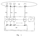
- In the published document of the Chinese patent titled "A method and apparatus for calibrating a smart antenna array" (CN 99 111350.0) (See Figure 1), a calibrating link is set by an
antenna element 201, acouple structure 205, aRF cable 206 and apilot transceiver 207 sequentially connected. Thecouple structure 205 sets up a RF couple connection with all the antenna elements 201-1, 201-2 ... 201-N of the smart antenna, and allocates the RF signals to all antenna elements constituting the array according to need. Thepilot transceiver 207 has the same structure as the other transceivers 203-1, 203-2...203-N of the base station and uses a commonlocal oscillator 208. Thepilot transceiver 207 works coherently with other transceivers and connects with thebaseband signal processor 204 via a digital bus. Each antenna element connects to a RF cable and further to a transceiver, and the connected antenna element, RF cable and transceiver form a transmitting link or a receiving link. Ac, A1, A2,...AN in Fig. 1 represent the connection points between the antenna elements and the RF cables 201-1, 201-2 ... 201-N, respectively; BC, B1, B2...BN represent the connection points of thepilot transceiver 207 and the radio transceivers 203-1, 203-2...203-N with thebaseband signal processor 204, respectively. - When making calibration, calibrate the calibration link first by using a network vector analyzer and record the receiving and transmitting transmission coefficients of the calibration link respectively, then perform the receiving calibration and transmitting calibration respectively. In the receiving calibration, the pilot transceiver transmits a signal at a given working frequency, and all the other links in the base station are set in the receiving state. Measure the outputs of all the receiving links and compute the ratio of the receiving transmission-coefficient (vector) of each link to the transmission-coefficient (vector) of a reference link. When the ratio of the amplitudes of the transmission-coefficients equals to 1, record the phase difference of each receiving link from the reference link. In the transmitting calibration, set one link after another of the base station in the transmitting state with all the other links close at the same time and the pilot transceiver will receive the signal of each transmitting link at a given working frequency, respectively; compute the ratio of the transmission-coefficient (vector) of each link during transmission to the transmission-coefficient (vector) of the reference link, and when the ratio of the amplitudes of the transmission-coefficients equals to 1, record the phase difference of every receiving link from the reference link.
- The patent mentioned above only relates to the general scheme of the method and apparatus for real-time calibration without a specific engineering implementation thereof, including the calibration sequence used in the transmitting and receiving calibration and the computation by the baseband signal processor, and how to perform the real-time calibration when the smart antenna is in operation. In addition, the transmitting calibration as described above is carried out with one link in the transmitting state at a time while all other links are in the receiving state, which is unfavorable for fast real-time calibration.
- It is the object of the present invention to provide a real-time calibration method for a smart antenna array and a method for generating the calibration signal so as to periodically calibrate the smart antenna array when a base station is in operation and compute the compensation coefficients for the transmitting and the receiving links of the smart antenna array to be calibrated.
- The technical solution to achieve the above object is as follows: A method for carrying out real-time calibration for a smart antenna array system comprising: a receiving calibration procedure and a transmitting calibration procedure; in the transmitting calibration, the transmitting links transmitting calibration signals simultaneously, while a calibration link receiving the combined signal thereof; in the receiving calibration, the calibration link transmitting a calibration signal, while all the receiving links receiving the signal simultaneously; a baseband signal processor computing the combined signal received by the calibration link or the signals received by every receiving links respectively and obtaining the compensation coefficients of each transmitting link and receiving link of the smart antenna array.
- pre-calibrating each antenna element of the smart antenna array and obtaining the transmitting compensation coefficient c TX / k and receiving compensation coefficient C RX / k of each antenna element relative to the calibration antenna element before performing the real-time transmitting and receiving calibration, wherein:
- A. generating the calibration signal for each antenna element through a periodic cycling shift of a basic calibration sequence, and the calibration signal generated is a calibration sequence with good anti-white-noise characteristics;
- B. in the transmitting calibration, the baseband signal processor first computing the amplitude and phase response of each transmitting link on the basis of the combined signal received by the calibration link, then computing, on the basis of the amplitude and phase response of each transmitting link and the transmitting compensation coefficients c TX / k obtained in the pre-calibration, the compensation coefficient of each transmitting link for compensating all the downlink data of the base station;
- C. in the receiving calibration, the baseband signal processor first computing the amplitude and phase response of each receiving link on the basis of the received signals of each receiving link, then computing, on the basis of the amplitude and phase response of each receiving link and the receiving compensation coefficients C RX / k obtained in the pre-calibration, the compensation coefficient of each receiving link for compensating all uplink data of the base station.
-
- The said pre-calibration before the real-time receiving and transmitting calibration further comprises: connecting one end of a network vector analyzer to the calibration antenna element, and connecting the other end of the network vector analyzer to each antenna element one by one; in the transmitting pre-calibration, the kth antenna element transmitting a fixed level data signal respectively, which is received by the calibration antenna element so that the transmitting compensation coefficient c TX / k between each antenna element and the calibration antenna element is obtained; in the receiving pre-calibration, the calibration antenna element transmitting a fixed level data signal, which is received by the kth antenna elements so that the receiving compensation coefficients C RX / k between the calibration antenna element and each antenna element is obtained, k = 1, ...N, and N is the number of antenna elements in the antenna array.
- The pre-calibration is carried out after the production of the smart antenna array. The transmitting and receiving compensation coefficients obtained will be stored. After the smart antenna array is installed on the site of the base station, the stored pre-calibration transmitting and receiving compensation coefficients obtained in the pre-calibration are inputted into the baseband signal processor of the base station.
- The length of said basic calibration sequence is W×N and the length of said calibration sequence is W×N+W-1, where N is the number of antenna elements in the antenna array, and W is the window length in channel estimation for each transmitting or receiving link.
- Said transmitting calibration and receiving calibration are periodically performed in the idle gap of the mobile communication system.
- In a TD-SCDMA system, said transmitting calibration and receiving calibration are performed in the protective gap (GP) between the uplink pilot time-slot and the downlink pilot time-slot in a frame.
- Said computing the compensation coefficient of each transmitting link in the transmitting calibration in said step B further comprises: first, obtaining the channel impulse response of each transmitting link; second, computing the amplitude and phase response of the path between each transmitting link, including the transceiver, and the calibration link antenna element; third, multiplying the amplitude and phase response with the transmitting compensation coefficient of the corresponding link obtained in pre-calibration, and then obtaining the transmitting compensation coefficient of each link.
- Said computing the compensation coefficient of each receiving link in the receiving calibration in said step C further comprises: first, obtaining the channel impulse response of each receiving link; second, computing the amplitude and phase response of the path between each receiving link, including the calibration link antenna element, and the transceiver; third, multiplying the amplitude and phase response with the receiving compensation coefficient of the corresponding link obtained in the pre-calibration, and then obtain the receiving compensation coefficient of each link.
- The technical solution to achieve the object of this invention also includes: a method for generating calibration signals for real-time calibration of a smart antenna array, comprising: generating the calibration signal by making a periodic cycling shift to a basic calibration sequence, which further comprises: taking a binary sequence mp as the basic calibration sequence with a length P; performing a phase equalization to the sequence mp to generate m p, a complex vector for the calibration sequence; expanding the m p periodically to obtain m, a new periodical complex vector; obtaining a calibration vector for each antenna element from the m; generating a calibration signal for each antenna element from the calibration vector for each antenna element.
- The real-time calibration method of this invention, for which it is necessary to set a calibration link specially for realizing the calibration function (as described in the background of the invention) which consists of an antenna element, a feeder cable and a pilot transceiver: before the delivery of the antenna array, first pre-calibrating the antenna array to obtain compensation coefficients of each antenna element relative to a calibration antenna element; then storing the compensation coefficients in the network operation and maintenance equipment; after the on-site installation of the smart antenna array, loading the compensation coefficient into the base station.
- Said calibration performed periodically while the base station is in operation further comprises: in the transmitting calibration, the transmitting links simultaneously transmitting a fixed level calibration sequence, which is received by the calibration link as a combined signal thereof; in the receiving calibration, the calibration link transmitting a fixed level calibration sequence, which is received simultaneously by the receiving links.
- By computing the said received signals according to the computation method provided by this invention, the compensation coefficients of the transmitting and receiving links of the smart antenna array can be obtained so that the real-time calibration can be accomplished.
- The fixed level calibration sequence employed is generated by a periodic cycling shift to a basic calibration sequence.
- The method of the present invention has the advantages of short computation time and simple controls. It is especially suitable for a smart antenna array in the third generation mobile communication system with high chip rate.
- Although the above solution is proposed mainly for CDMA wireless communication systems, the method of the present invention is fully applicable, after simple modification, to frequency division multiple access and time division multiple access wireless communication systems. It can not only be used to calibrate a smart antenna operating in TDD mode, but also a smart antenna operating in FDD mode.
- By calibrating a smart antenna array with the method of the present invention, beams of the smart antenna array are greatly improved and the transmitting powers are decreased, resulting in a good implementation of the smart antenna technology.
-
- Figure 1 is a schematic diagram for the configuration of a base station with a smart antenna array comprising a calibration link.
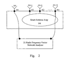
- Figure 2 is a schematic diagram for the layout of pre-calibration of a smart antenna array.
-
- The method of the present invention is proposed on the basis of an antenna array which is a passive microwave (radio frequency) network. Characteristics of mutual coupling between each antenna element of this antenna array and the calibration antenna element remain unchanged at a given working frequency provided that the design of the antenna array product has been finalized and the structure thereof is fixed. Therefore, before delivery of the antenna array, each antenna element of the antenna array can be tested relative to the calibration antenna element at a given working frequency or can be pre-calibrated to obtain the compensation coefficient of each antenna element relative to the calibration antenna element which is then stored in the network management database as the pre-calibration data. After the antenna array has been installed on site, the antenna array pre-calibration data are loaded to the base station by the network operation and maintenance equipment, such as OMC_R or LMT. In this way, the antenna array can be calibrated with the real-time calibration method according to the present invention when the antenna array starts into operation.
- The method of the invention can be employed in a typical time-division duplex (TDD) CDMA base station equipped with a smart antenna. The configuration of the base station is shown in Fig. 1. The base station comprises N identical antenna elements 201-1, 201-2 ... 201-N; N identical feeder cables 202-1, 202-2 ... 202-N; N RF transceivers 203-1, 203-2 ... 203-N that work coherently; and an appropriate
baseband signal processor 204. In order to implement the calibration, a calibration (reference) link is also established, which consists of aRF coupling structure 205, acalibration antenna element 201, afeeder cable 206 and apilot transceiver 207, wherein thepilot transceiver 207 works coherently with N transceivers 203-1, 203-2 ... 203-N, and uses a commonlocal oscillator 208. N transceivers 203-1, 203-2 ... 203-N and thepilot transceiver 207 connect with thebaseband signal processor 204 via a data bus. - The real-time calibration method of the present invention comprises the following key steps:
- The First step: before delivery of the smart antenna array, pre-calibrating each antenna element using a radio frequency (microwave) network vector analyzer to obtain the compensation coefficient for each antenna element relative to the calibration antenna element.
- Refer to Fig. 2, in pre-calibration, with one end of the radio frequency
network vector analyzer 21 connected to the antenna element of thecalibration link 201 through the point Ac and the other end connected to the antenna elements 201-1, 201-2 ... 201-N of thesmart antenna array 208 in proper order through the points A1, A2 ... AN, the radio frequencynetwork vector analyzer 21 performs the transmitting and receiving pre-calibration respectively. - If the structure of the smart antenna is rather firm by design, it can be recognized that the channel characteristics between each antenna element 201-1, 201-2 ... 201-N and the
calibration antenna unit 201 remain unchanged on the whole with the environmental conditions at a fixed working frequency, given that there is no disruption of the relative location. So it is possible to perform the pre-calibration measurement using a radio frequency network vector analyzer. - In the transmitting pre-calibration, a fixed level digital signal is transmitted by each antenna element of 201-1, 201-2 ... 201-N, respectively, and the signal is received by the antenna element of the
calibration link 201; the radio frequencynetwork vector analyzer 21 measures and computes the transmitting compensation coefficient c TX / i (TX represents transmitting) between A i ( i=1 , ...N ) and A c , thus the transmitting compensation coefficient c TX / i between each antenna element of 201-1, 201-2 ... 201-N and thecalibration antenna element 201 is obtained. In the receiving pre-calibration, the said antenna element of thecalibration link 201 transmits a fixed level digital signal, which is received by each antenna element 201-1, 201-2 ... 201-N; the radio frequencynetwork vector analyzer 21 measures and computes the receiving compensation coefficient c RX / i (RX represents receiving) between A c and A i (i=1 , ...N), thus the receiving compensation coefficient c RX / i between thecalibration antenna element 201 and each antenna element 201-1, 201-2 ... 201-N is obtained. - In general, in a base station of TDD CDMA system, since each transceiver is connected to the same antenna element (i.e. the transmitting and receiving links have a common antenna element), the measured transmitting compensation coefficient of each antenna element equals to the receiving compensation coefficient thereof, i.e. c TX / i = c RX / i.
- In an FDD CDMA system, however, when the smart antenna technology is employed, different antenna arrays are usually used for transmitting and receiving, respectively, in order to isolate the transmitting link from the receiving link. Therefore, each antenna element of the two antenna arrays should be measured and pre-calibrated respectively.
- The second step: inputting the above pre-calibration result (the transmitting compensation coefficient and the receiving compensation coefficient) in the network operation and maintenance equipment. After the antenna array has been installed on site, the antenna array compensation coefficients are loaded to the baseband signal processor of the base station to which the antenna array is connected by the network operation and maintenance equipment, such as OMC_R or LMT.
- The third step is carried out while the base station starts operation or is in operation. This step comprises: generating a calibration sequence; performing the transmitting calibration; performing the receiving calibration; and computing the transmitting and receiving compensation coefficients.
- The calibration sequence is generated by a periodic cycling shift of a basic calibration sequence selected with good anti-white-noise characteristics. The length of the basic calibration sequence P is W×N, where N is the number of operating antenna elements of the antenna array, and W is the window length in the channel estimation of each link. The length of the calibration sequence when performing the transmitting and receiving calibration is W×N + W - 1, that is, P + W - 1.
- Since W relates only to the inconsistency of the hardware time-delay of each antenna element (usually very small), the calibration duration is very short when carrying out calibration by using the method of the present invention. In some systems where the calibration duration is limited, N can take a larger value in order to have a larger antenna gain for the system.
- The procedure for generating the calibration sequence from the basic calibration sequence is as follows:
- (1) Take a binary sequence m P with the length of P as the basic calibration sequence, where m P = (m 1,m 2,...,m P ), P = W×N (select a power of 2 as P to simplify the computation);
- (2) In order to avoid an abrupt phase change and increase the calibration accuracy, make a phase equalization of the basic calibration sequence m P to generate a complex vector of the calibration sequence m P; m P = ( m 1, m 2,...,m P ), where the element m i is derived from the corresponding element m i of the sequence m P, m i = (j) i-1 · m i , (i = 1 ...P), and j is the square root of (-1), in this way the phase equalization is implemented;
- (3) In order to generate the calibration sequence for each antenna element, the
basic calibration sequence is periodically expanded to obtain a new complex vector m ,
m = ( m 1, m 2,..., m i
max ) = ( m 2, m 3 ,..., m p , m 1, m 2,..., m p ); - (4) The calibration sequence vector of each antenna element can be obtained from
this periodical complex vector, and a fixed level calibration signal is thereby generated:
the sequence vector m (k) = ( m (k) / 1, m (k) / 2,..., m (k) / Lm), k = 1 ... N, Lm = P+W-1 (Lm is the window length, i.e. the length of the transmitting calibration sequence). -
- An element of the sequence vector m (k) / i = m i+(N-k)W , i = 1,...,L m and k = 1,..., N (k represents any antenna element of an operating antenna array).
- At the same time, a vector S relating to the basic calibration sequence should be computed for this invention as well, which is stored in the baseband signal processor as a constant vector for computing the compensation coefficients when performing the transmitting and receiving calibrations:
m - The said selecting the basic calibration sequence step refers to selecting a binary sequence which makes S have a minimum norm and has a length P.
The transmitting calibration comprises the following steps: each antenna element transmitting a fixed level calibration sequence simultaneously, and the calibration link receiving the combined signal thereof. With the algorithm provided by the present invention, the baseband signal processor processing the signal data received by the calibration link, computing the amplitude and phase response of each transmitting link, and then computing the compensation coefficient (including the amplitude and the phase compensation) for each transmitting link according to the compensation coefficient (transmitting compensation coefficient) thereof obtained during pre-calibration, by which all the downlink data of the base station are compensated at the baseband signal processor. - Taking the base station in Fig. 1 as an example, N transmitting links transmit calibration sequence vectors m (k) with a certain power level at point B k (k=1, ...N). Through the transceivers 203-1 ... 203-N, the feeder cables 202-1 ... 202-N, the antenna elements 201-1 ... 201-N and the antenna
array couple structure 205, the fixed level signals are received by the calibrationlink antenna element 201. The baseband signal processor computes the received data from the calibration link (201, 206 and 207) to obtain the amplitude and phase response of each transmitting link B k → A k . In fact, the amplitude and phase response of the link Bk→ Ak→ AC→ BC is needed. Since the amplitude and phase response of the path Ak→ AC has been obtained in the pre-calibration, only the amplitude and phase response of the path B k → A k needs to be computed. - Suppose R is the complex vector received from the baseband signal processor after each transmitting calibration sequence signal of the antenna elements 201-1 ... 201-N is accumulated in the calibration
link antenna unit 201, the receiving sequence:r - A Channel Impulse Response (CIR) sequence with a length of P can be obtained by operation of the following formula: CIR = (c 1,c 2,...,c p ) = ifft(fft( R P.S)), where represents a point multiplication, fft represents the Fast Fourier Transform Algorithm, ifft represents the Inverse Fast Fourier Transform Algorithm, S is the constant vector obtained as described above.
- Multiply the CIR k with the transmitting compensation coefficient c TX / k of the path Ak→ AC of the kth link obtained in the pre-calibration, then obtain:
- The receiving calibration comprises the following steps: the calibration link transmitting a fixed level calibration sequence signal, which is received by each receiving link simultaneously. The baseband signal processor computing the amplitude and phase response of each receiving link on the basis of the received data at each receiving link, by which and the receiving compensation coefficient obtained in the pre-calibration the compensation coefficient (including the amplitude and phase compensation) of each receiving link is computed and obtained. With the compensation coefficients, all downlink data of the base station can be compensated in the baseband signal processor.
- Also taking the base station in Fig. 1 as an example, the calibration link (201, 206 and 207) transmits a calibration vector signal with a certain power level m (k) (k = 1, ... N) at point B c . The signal is received by each receiving link through the
couple structure 205, each antenna element of the antenna array 201-1 ... 201-N each feeder cable 202-1, ...202-N, each transceiver 203-1, ...203-N.Thebaseband signal processor 204 computes the data received from each receiving link to obtain the amplitude and phase response of each receiving link (A k → B k ). In fact, the amplitude and phase response of the path B c → A c → A k → B k is needed, since the amplitude and phase response of the path A c → A k have been obtained in pre-calibration, only the amplitude and phase response of the path A k → B k needs to be computed. - Suppose R k is the complex vector of each link received in the
baseband signal processor 204, the receiving sequence:k - Intercept a section from the receiving sequence with a length that equals to the length of the basic calibration sequence P, R k / P = ( r k / 1, r k / 2,..., r k / p). Suppose the interception is made in the middle of the sequence (there could be various ways of interception) as represented in the following formula, R k p = (r k / w-1,r k / w ,...,r k / w+p-2) k = 1, ..., N.
- A Channel Impulse Response (CIR) sequence with the length of P can be obtained by operation of the following formula: CIR k = (c k / 1,c k / 2,...,c k / p) = ifft(fft( R k / p.S)), k = 1, ...N, where represents a point multiplication, fft represents the Fast Fourier Transform Algorithm, ifft represents the Inverse Fast Fourier Transform Algorithm, and S is the constant vector obtained as described above.
- Compute CIR k = f max(c k / 1,c k / 2...,c k / p), k = 1, ... N, f max is an interpolation function to evaluate the peak between the channel estimation results c k / 1 ~ c k / w×k of the kth receiving link (the specific value depends on the required computation accuracy), CIR k is a complex number containing the amplitude and phase response of the path B k → A c of the kth link.
- Multiply the CIR k with the receiving compensation coefficient C RX / k of the path Ac → A k of the kth link obtained in the pre-calibration, and obtain:
- The formulas adopted in this invention for computing the compensation coefficient are as follows:
- First, compute the mean power of each link, which is carried out for the transmitting link and receiving link respectively, that is, CIR k ' in the following formula is the result of the transmitting calibration and the receiving calibration, respectively.

- In this way, the transmitting compensation coefficient and the receiving compensation coefficient can be computed respectively by the following formula. While computing the compensation power of the receiving link, use the mean power of the receiving link and the CIR ' / k obtained in the receiving calibration, and while computing the compensation power of transmitting link, use the mean power of the transmitting link and the CIR ' / k obtained in the transmitting calibration:
- Although the descriptions above are given with reference to the structure of a TDD CDMA base station, the calibration method is independent of the transinitting calibration and the receiving calibration, so the method of the present invention can also be implemented in an FDD CDMA base station which use different smart antenna arrays to transmit and receive signals.
- In the present invention, data transmitted and received are compensated respectively by the baseband signal processor using the transmitting compensation coefficient and the receiving compensation coefficient computed. Thus a software implementation of real-time calibration of a smart antenna array is achieved.
- In practice, it is not likely for a mobile communication system to run in full load all the time. There would always be some idle gaps which can be used for real-time calibration. For TD-SCDMA system, a third generation mobile communication system, the Gad Period (GP) between the Uplink Pilot Time-Slot (UpPTS) and the Downlink Pilot Time-Slot (DwPTS) in a frame can be used for the real-time calibration.
- The calibration by this method can be periodically performed while the base station is in operation.
- Any person skilled in the art of smart antenna calibration with an understanding of the basic principles thereof can easily implement the real-time calibration of a smart antenna array by referring to the method of this invention.
Claims (13)
- A method for calibrating smart antenna array systems in real time, comprising: a receiving calibration procedure and a transmitting calibration procedure; in the transmitting calibration, a plurality of transmitting links transmitting calibration signals simultaneously, and a calibration link receiving the combined signal thereof; in the receiving calibration, the calibration link transmitting a calibration signal, and the receiving links receiving the signal simultaneously; a baseband signal processor processing the combined signal received by the calibration link and the signals received by the receiving links, respectively, to obtain the compensation coefficients of each transmitting link and each receiving link of the smart antenna array; before performing the real-time transmitting and receiving calibration, pre-calibrating each antenna element of the smart antenna array to obtain the transmitting compensation coefficient c TX / k and the receiving compensation coefficient C RX / k of each antenna element relative to the calibration antenna element; wherein:A. generating the calibration signal for each antenna element by a periodic cycling shift of a basic calibration sequence and the calibration signal is a calibration sequence with good anti-white-noise characteristics;B. in the transmitting calibration, the baseband signal processor first computing the amplitude and phase response of each transmitting link on the basis of the combined signal received by the calibration link, then computing the compensation coefficient of each transmitting link on the basis of the amplitude and phase response of each transmitting link and the transmitting compensation coefficients c TX / k obtained in the pre-calibration for compensating all the downlink data of the base station;C. in the receiving calibration, the baseband signal processor first computing the amplitude and phase response of each receiving link on the basis of the received signals of each receiving link, then computing the compensation coefficient of each receiving link on the basis of the amplitude and phase response of each receiving link and the receiving compensation coefficients C RX / k obtained in the pre-calibration for compensating all the uplink data of the base station.
- A method according to claim 1, wherein the said pre-calibration before performing the real-time receiving calibration and transmitting calibration further comprising: connecting one end of a network vector analyzer to the calibration antenna element and the other end of the network vector analyzer to each antenna element one by one; in the transmitting pre-calibration, the kth antenna element transmitting a fixed level data signal sequentially, the calibration antenna element receiving the signal, then obtaining the transmitting compensation coefficient c TX / k between each antenna element and the calibration antenna element; in the receiving pre-calibration, the calibration antenna element transmitting a fixed level data signal, the kth antenna elements receiving the signal, then obtaining the receiving compensation coefficients C RX / k between the calibration antenna element and each antenna element, where k = 1, ...N, and N is the number of the antenna elements in the antenna array.
- A method according to claim 1, wherein, in the said step A, the said generating a calibration signal by a periodic cycling shift of a basic calibration sequence further comprising:taking a binary sequence mp with a length P as the basic calibration sequence;performing a phase equalization to the sequence mp to generate a complex vector of calibration sequence m p;expanding the m p periodically to obtain a new periodical complex vector m;obtaining a calibration vector for each antenna element from the m;generating the said calibration signal for each antenna element from the calibration vector for each antenna element.
- A method according to claim 3, wherein the said P is selected as a power of 2.
- A method according to claim 1, wherein the said transmitting calibration and receiving calibration in step B and C are periodically performed in the idle gap of a mobile communication system.
- A method according to claim 1, wherein, in a TD-SCDMA system, the said transmitting calibration and receiving calibration in step B and C are periodically performed in the guard period between uplink pilot time-slot and downlink pilot time-slot in a frame.
- A method according to claim 1, wherein computing the compensation coefficient of each transmitting link in the transmitting calibration in the said step B further comprising:b1. obtaining the complex vector of the combined signal received by the calibration link R = (r 1, r 2 ,..., r l ), where l = P+2×(w-1), P = w×N represents the length of the said basic calibration sequence, N is the number of the antenna elements of the smart antenna array, and w is the window length in the channel estimation of each transmitting link;b2. intercepting from the vector a section R p = ( r 1,r 2, ..., r p ) with a length equals to that of the basic calibration sequence P;b3. computing a Channel Impulse Response sequence with a length P using the formula CIR = (c 1,c 2,...,c p ) = ifft( fft( R P.S)), where S is a constant vector; computing a Channel Impulse Response sequence with a length P using the formula CIR k = (c k / 1,c k / 2,...,c k / p) = ifft( fft( R k / p.S)), where k=1..N, S is a constant vector;b4. computing an interpolation function of the peak value between the channel estimation results c w×(k-1)+1 ~c w×k of the kth transmitting link: CIR k = f max(c w×(k-1)+1,...,c w×k ), and obtaining the amplitude and phase response of the kth link including the path between the transmitter and the antenna element of the calibration link, k = 1, ...N;b5. multiplying CIR k with the transmitting compensation coefficient c TX / k of the kth link obtained in the pre-calibration, obtaining the amplitude and phase response of the kth link including the path between the transmitter and the antenna element thereof:b6. computing the mean power of a transmitting link with the following formula:
 b7. computing the transmitting compensation coefficient of each transmitting link with the following formula: Corr_factork = sqrt(Mean_power)/ CIR ' / k, where sqrt ( ) represents a square root function.
 - A method according to claim 7, wherein the said Step b2 is performed by intercepting a part of the sequence as expressed by the following formula R p = (r w-1, r w ,...,r w+p-2).
- A method according to claim 7, wherein the constant vector S in Step b3 is computed by the formula: S = 1./ fft( m P) = 1./ fft( m 1, m 2,..., m P ), where the complex vector of the calibration sequence, m P = ( m 1, m 2,..., m P ), is generated by a phase equalization to the basic calibration sequence m P = (m 1,m 2,...,m P ), the element of the sequence m i = (j) i-1 · m i , i = 1, ...P, P = w×N represents the length of the said basic calibration sequence, N is the number of antenna elements of the smart antenna array, and w is the window length in channel estimation of each transmitting link.
- A method according to claim 1, wherein computing the compensation coefficient of each receiving link in the receiving calibration in the said step C, further comprising:c1. obtaining a complex vector sequence of the signal received by each receiving link R k = (r k / 1,r k / 2,...,r k / l), where l = P+2×(w-1), k = 1, ..N, P = w×N represents the length of the basic calibration sequence, N is the number of antenna elements of the smart antenna array, and w is the window length of channel estimation of each receiving link;c2. intercepting from the sequence a section with a length equals to that of the basic calibration sequence P, R k / P = ( r k / 1, r k / 2,..., r k / p) k = 1, ...N;c3. obtaining a Channel Impulse Response sequence with a length P by the formula CIR k = (c k / 1,c k / 2,...,c k / p) = ifft( fft( R k / p .S)), where k = 1, ...N and S is a constant vector;c4. computing the interpolation function of the peak value between the channel estimation results c k / 1 ~ c k / w×k of the kth receiving link with CIR k = f max(c k / 1, c k / 2, ..., c k / p), obtaining the amplitude and phase response of the kth receiving link including the path between the antenna element of the calibration link and the RF receiver, k = 1, ...N;c5. multiplying CIR k with the receiving compensation coefficient C RX / k of the kth link obtained in the pre-calibration, obtaining the amplitude and phase response of the kth receiving link including the path between the antenna element and the RF receiver,c6. computing the mean power of a receiving link with the formula:
 c7. computing a receiving compensation coefficient of each receiving link with the formula: Corr_factork = sqrt(Mean_power)/ CIR ' / k, where k = 1, ... N and sqrt( ) represents a square root function.
 - A method according to claim 10, wherein the said step c2 is performed by intercepting a part of the sequence as expressed by the formula
- A method according to claim 10, wherein the said constant vector S in the said step c3 is computed with the formula: S = 1./ fft( m P) = 1./ fft( m 1, m 2,..., m P ), where the complex vector of the calibration sequence m P = ( m 1, m 2,..., m P ) is generated by a phase equalization to the basic calibration sequence m P = (m 1,m 2,...,m P ), the element of the sequence m i = (j) i-1 · m i , i = 1, ...P, P = w×N represents the length of the basic calibration sequence, N is the number of the antenna elements of the smart antenna array, and w is the window length of channel estimation of each receiving link.
- A method for generating a calibration sequence of signal for the real-time calibration of a smart antenna array by a periodic cycling shift of a basic calibration sequence, comprising:a1. taking a binary sequence mp with the length P as the basic calibration sequence, m P = (m 1,m 2,...,m P ), where P = w×N, N is the number of the antenna elements of the smart antenna array, and w is the window length of channel estimation of each transmitting or receiving link;a2. performing a phase equalization to the sequence mp, generating a complex vector of the calibration sequence m p, m P = ( m 1, m 2,..., m P ), where the element of the sequence m i = (j) i-1 · m i , i = 1, ...P, and j is the square root of-1;a3. expanding m p periodically and obtaining a new periodical complex vector m, m = ( m 1 ,m 2,..., m i
max ) = ( m 2, m 3,..., m p , m 1, m 2,..., m p );a4. obtaining a calibration sequence vector with a length Lm=P+w-1 for each antenna element from the periodical complex vector m, m (k) = ( m (k) / 1,m (k) / 2,..., m (k) / L m ), k = 1, ...N, an element of the calibration sequence vector m (k) / i = m i+(N-k)W , i = 1, ...Lm and k=1,...N;a5. generating a calibration sequence of signal with a fixed power from the calibration sequence vector on the basis of the calibration requirement.
Applications Claiming Priority (3)
| Application Number | Priority Date | Filing Date | Title |
|---|---|---|---|
| CN02158623 | 2002-12-25 | ||
| CNB021586233A CN1176555C (en) | 2002-12-25 | 2002-12-25 | Method for adjusting intelligences antenna array system in real time |
| PCT/CN2003/001118 WO2004059868A1 (en) | 2002-12-25 | 2003-12-25 | A method for calibrating smart antenna array systems in real time |
Publications (3)
| Publication Number | Publication Date |
|---|---|
| EP1585231A1 true EP1585231A1 (en) | 2005-10-12 |
| EP1585231A4 EP1585231A4 (en) | 2006-12-06 |
| EP1585231B1 EP1585231B1 (en) | 2009-10-07 |
Family
ID=27811378
Family Applications (1)
| Application Number | Title | Priority Date | Filing Date |
|---|---|---|---|
| EP03782075A Expired - Lifetime EP1585231B1 (en) | 2002-12-25 | 2003-12-25 | A method for calibrating smart antenna array systems in real time |
Country Status (9)
| Country | Link |
|---|---|
| US (1) | US7102569B2 (en) |
| EP (1) | EP1585231B1 (en) |
| JP (1) | JP4452628B2 (en) |
| KR (1) | KR100656979B1 (en) |
| CN (1) | CN1176555C (en) |
| AT (1) | ATE445264T1 (en) |
| AU (1) | AU2003292870A1 (en) |
| DE (1) | DE60329629D1 (en) |
| WO (1) | WO2004059868A1 (en) |
Cited By (3)
| Publication number | Priority date | Publication date | Assignee | Title |
|---|---|---|---|---|
| US8311166B2 (en) | 2010-03-31 | 2012-11-13 | Ubidyne, Inc. | Active antenna array and method for calibration of the active antenna array |
| US8340612B2 (en) | 2010-03-31 | 2012-12-25 | Ubidyne, Inc. | Active antenna array and method for calibration of the active antenna array |
| US8441966B2 (en) | 2010-03-31 | 2013-05-14 | Ubidyne Inc. | Active antenna array and method for calibration of receive paths in said array |
Families Citing this family (72)
| Publication number | Priority date | Publication date | Assignee | Title |
|---|---|---|---|---|
| AU2003296229A1 (en) * | 2003-12-31 | 2005-08-12 | Zte Corporation | Adjust equipment and method for array antenna transmitting link |
| CN100399719C (en) * | 2005-02-03 | 2008-07-02 | 芯通科技(成都)有限公司 | Calibrating method for intelligent antenna array and radio frequency receiving-transmitting machine |
| US20060240784A1 (en) * | 2005-04-22 | 2006-10-26 | Qualcomm Incorporated | Antenna array calibration for wireless communication systems |
| US8498669B2 (en) | 2005-06-16 | 2013-07-30 | Qualcomm Incorporated | Antenna array calibration for wireless communication systems |
| US8320903B2 (en) * | 2005-09-07 | 2012-11-27 | Samsung Electronics Co., Ltd. | Method and system for calibrating multiple types of base stations in a wireless network |
| US7672668B2 (en) * | 2005-09-07 | 2010-03-02 | Samsung Electronics Co., Ltd. | Calibration system architecture for calibrating multiple types of base stations in a wireless network |
| US9118111B2 (en) | 2005-11-02 | 2015-08-25 | Qualcomm Incorporated | Antenna array calibration for wireless communication systems |
| US8280430B2 (en) | 2005-11-02 | 2012-10-02 | Qualcomm Incorporated | Antenna array calibration for multi-input multi-output wireless communication systems |
| US8295884B2 (en) * | 2005-11-22 | 2012-10-23 | Samsung Electronics Co., Ltd | Method and system for providing digital compensation and vector calibration for a base station in a wireless network |
| CN101064902B (en) * | 2006-04-25 | 2010-11-10 | 大唐移动通信设备有限公司 | Method for real-time calibrating intelligent antenna |
| CN101080031B (en) * | 2006-05-26 | 2011-02-02 | 大唐移动通信设备有限公司 | Intelligent antenna calibration system based on base band remote push technology and its method |
| CN101188448B (en) * | 2006-11-15 | 2011-09-14 | 电信科学技术研究院 | A smart antenna calibration method, device and system |
| US8055300B2 (en) * | 2007-08-29 | 2011-11-08 | Telefonaktiebolaget Lm Ericsson (Publ) | System and method for indoor coverage of user equipment terminals |
| AU2008291897B2 (en) * | 2007-08-31 | 2013-03-07 | Bae Systems Plc | Antenna calibration |
| AU2008291898B2 (en) | 2007-08-31 | 2013-09-05 | Bae Systems Plc | Antenna calibration |
| AU2008291900A1 (en) * | 2007-08-31 | 2009-03-05 | Bae Systems Plc | Antenna calibration |
| US8004456B2 (en) * | 2007-08-31 | 2011-08-23 | Bae Systems Plc | Antenna calibration |
| CN101383647B (en) * | 2007-09-06 | 2012-01-11 | 电信科学技术研究院 | Method and device for calibrating operation antenna |
| CN101227242B (en) * | 2008-01-31 | 2011-06-01 | 西安交通大学 | Method for forming distributed aerial array beam based on channel correction |
| JP4471006B2 (en) | 2008-02-04 | 2010-06-02 | ソニー株式会社 | Wireless communication apparatus, antenna calibration method, and program |
| CN101552994B (en) * | 2008-04-02 | 2011-04-20 | 大唐移动通信设备有限公司 | Method and device for staggering receiving calibration and transmitting calibration |
| GB2461082A (en) * | 2008-06-20 | 2009-12-23 | Ubidyne Inc | Antenna array calibration with reduced interference from a payload signal |
| JP5153507B2 (en) * | 2008-08-04 | 2013-02-27 | 三菱電機株式会社 | Wireless communication device |
| US8193971B2 (en) * | 2008-11-10 | 2012-06-05 | Motorola Mobility, Inc. | Antenna reciprocity calibration |
| US8489041B2 (en) * | 2009-06-08 | 2013-07-16 | Anthony Teillet | Multi-element amplitude and phase compensated antenna array with adaptive pre-distortion for wireless network |
| US8731005B2 (en) | 2009-10-12 | 2014-05-20 | Kathrein-Werke Kg | Absolute timing and Tx power calibration of the Tx path in a distributed system |
| KR101285388B1 (en) * | 2009-12-18 | 2013-07-10 | 한국전자통신연구원 | Beam steering apparatus |
| CN102136858B (en) * | 2010-01-25 | 2014-07-02 | 中国移动通信集团公司 | Base station correction method and correction device |
| CN102111202B (en) * | 2010-02-05 | 2014-05-21 | 电信科学技术研究院 | Antenna calibration method and device |
| US8634766B2 (en) | 2010-02-16 | 2014-01-21 | Andrew Llc | Gain measurement and monitoring for wireless communication systems |
| US8374826B2 (en) | 2010-02-22 | 2013-02-12 | Ubidyne, Inc. | System, apparatus and method for calibrating a delay along a signal path |
| US8599861B2 (en) | 2010-06-03 | 2013-12-03 | Kathrein-Werke Kg | Active antenna array and method for relaying radio signals |
| US8774196B2 (en) | 2010-06-03 | 2014-07-08 | Kathrein-Werke Kg | Active antenna array and method for relaying radio signals with synchronous digital data interface |
| JP5613829B2 (en) * | 2010-06-03 | 2014-10-29 | ノキア シーメンス ネットワークス オサケユキチュア | Base station calibration |
| US8791767B2 (en) * | 2010-10-29 | 2014-07-29 | Qualcomm Incorporated | Package inductance compensating tunable capacitor circuit |
| CN102148636B (en) * | 2011-01-27 | 2013-09-04 | 大唐移动通信设备有限公司 | Antenna calibration method and system |
| US9295006B2 (en) | 2011-02-09 | 2016-03-22 | Qualcomm Incorporated | Real-time calibration of an air to ground communication system |
| CN102651672B (en) * | 2011-02-25 | 2015-02-04 | 中国移动通信集团公司 | Base station calibration method and device for cooperative multiple input multiple output (MIMO) system |
| GB2489002A (en) * | 2011-03-14 | 2012-09-19 | Nujira Ltd | Delay adjustment to reduce distortion in an envelope tracking transmitter |
| CN102790636B (en) * | 2011-05-17 | 2015-01-28 | 普天信息技术研究院有限公司 | Method for transmitting intelligent antenna calibration sequence |
| US8970427B2 (en) | 2011-05-18 | 2015-03-03 | Mediatek Singapore Pte. Ltd. | Phase-arrayed device and method for calibrating the phase-arrayed device |
| US9319172B2 (en) | 2011-10-14 | 2016-04-19 | Qualcomm Incorporated | Interference mitigation techniques for air to ground systems |
| EP2769483A4 (en) * | 2011-10-21 | 2015-07-01 | Optis Cellular Technology Llc | Methods, processing device, computer programs, computer program products and antenna apparatus for calibration of antenna apparatus |
| CN102497223B (en) * | 2011-12-05 | 2014-01-15 | 北京北方烽火科技有限公司 | Method and device for calibrating time division-long term evolution (TD-LTE) antenna array |
| CN102412917B (en) * | 2011-12-16 | 2014-04-16 | 哈尔滨工业大学深圳研究生院 | Multiple-antenna measurement system and method based on network analyzer and RF (radio frequency) switch |
| CN104718713B (en) * | 2012-09-13 | 2019-01-01 | 爱立信(中国)通信有限公司 | Method and apparatus for antenna calibration |
| CN102932039B (en) * | 2012-10-17 | 2015-03-25 | 大唐移动通信设备有限公司 | Antenna calibration method and system |
| CN103916168B (en) * | 2013-01-04 | 2018-02-23 | 中国移动通信集团公司 | A kind of antenna calibration method and device |
| CN103916176B (en) * | 2013-01-04 | 2018-08-10 | 中国移动通信集团公司 | A kind of wireless discharging-directly station and its antenna calibration method |
| CN103117786B (en) * | 2013-01-18 | 2015-10-07 | 大唐移动通信设备有限公司 | A kind of antenna array calibration method and system |
| JP6329348B2 (en) * | 2013-08-13 | 2018-05-23 | 株式会社Nttドコモ | Base station apparatus and calibration method |
| GB2517217B (en) * | 2013-08-16 | 2018-03-21 | Analog Devices Global | Communication unit, integrated circuit and method for generating a plurality of sectored beams |
| WO2016090548A1 (en) * | 2014-12-09 | 2016-06-16 | 华为技术有限公司 | Method for determining calibration weight coefficient and base station |
| KR101556067B1 (en) | 2014-12-12 | 2015-10-13 | 한국항공우주연구원 | Apparatus and method for phase error detection in active array antenna |
| CN104702351B (en) * | 2015-01-07 | 2017-05-17 | 成都九洲迪飞科技有限责任公司 | Antenna calibration method |
| GB2543563B (en) * | 2015-10-23 | 2020-02-12 | Cambium Networks Ltd | Method and Apparatus for Controlling Equivalent Isotropic Radiated Power |
| WO2017145257A1 (en) * | 2016-02-23 | 2017-08-31 | 三菱電機株式会社 | Array antenna device and calibration method therefor |
| US10263330B2 (en) * | 2016-05-26 | 2019-04-16 | Nokia Solutions And Networks Oy | Antenna elements and apparatus suitable for AAS calibration by selective couplerline and TRX RF subgroups |
| DE102016212136A1 (en) * | 2016-07-04 | 2018-01-04 | Laird Bochum GmbH | Method and device for determining a distance and vehicle |
| JP6645369B2 (en) | 2016-07-06 | 2020-02-14 | 富士通株式会社 | Wireless communication system and base station |
| CN107782979B (en) * | 2016-08-25 | 2019-04-09 | 西安电子科技大学 | Utilize the method and device of vector network analyzer detection electromagnetic wave vortex state |
| EP3293897B8 (en) | 2016-09-12 | 2020-08-12 | Rohde & Schwarz GmbH & Co. KG | System and method for characterization of multi-element antenna |
| CN110178315B (en) * | 2017-01-24 | 2020-10-23 | 华为技术有限公司 | Antenna correction method and device |
| US10128894B1 (en) * | 2017-05-09 | 2018-11-13 | Analog Devices Global | Active antenna calibration |
| WO2019153186A1 (en) * | 2018-02-08 | 2019-08-15 | 上海诺基亚贝尔股份有限公司 | Method and apparatus for blindly calibrating antenna array |
| CN110768701B (en) * | 2018-07-27 | 2022-10-28 | 中兴通讯股份有限公司 | Channel state processing method, device, system, terminal, base station and storage medium |
| US11276928B1 (en) | 2019-04-10 | 2022-03-15 | The Governors Of The University Of Alberta | Calibrating/monitoring method and apparatus for phased array antenna employing very near field |
| CN110429993B (en) * | 2019-06-17 | 2022-01-25 | 北京睿信丰科技有限公司 | Broadband single-carrier antenna calibration method and calibration system |
| WO2020256607A1 (en) * | 2019-06-20 | 2020-12-24 | Telefonaktiebolaget Lm Ericsson (Publ) | Network node and method in a wireless communications network |
| CN111490835B (en) * | 2020-03-05 | 2022-08-26 | 西安宇飞电子技术有限公司 | Self-calibration method, device and equipment for narrow-band signal |
| JP7012914B1 (en) * | 2020-03-23 | 2022-01-28 | 三菱電機株式会社 | Array antenna calibration device and calibration method |
| CN115913404A (en) * | 2021-09-30 | 2023-04-04 | 深圳市中兴微电子技术有限公司 | Antenna calibration method and device and remote radio frequency unit |
Citations (5)
| Publication number | Priority date | Publication date | Assignee | Title |
|---|---|---|---|---|
| EP0805510A2 (en) * | 1996-05-02 | 1997-11-05 | HE HOLDINGS, INC. dba HUGHES ELECTRONICS | Active array self calibration |
| WO2001019101A1 (en) * | 1999-09-10 | 2001-03-15 | Utstarcom. Inc. | Method and apparatus for calibrating a smart antenna array |
| EP1085684A2 (en) * | 1999-09-14 | 2001-03-21 | Hitachi, Ltd. | Antenna unit and radio base station |
| EP1204161A1 (en) * | 1999-08-10 | 2002-05-08 | China Academy of Telecommunications Technology, MII | Method and apparatus for calibrating smart antenna array |
| EP1548957A1 (en) * | 2002-09-13 | 2005-06-29 | Da Tang Mobile Communications Equipment Co., Ltd. | Method for calibrating smart antenna array in real time |
Family Cites Families (4)
| Publication number | Priority date | Publication date | Assignee | Title |
|---|---|---|---|---|
| US5546090A (en) * | 1991-12-12 | 1996-08-13 | Arraycomm, Inc. | Method and apparatus for calibrating antenna arrays |
| US6157343A (en) * | 1996-09-09 | 2000-12-05 | Telefonaktiebolaget Lm Ericsson | Antenna array calibration |
| CN1078390C (en) * | 1994-06-03 | 2002-01-23 | 艾利森电话股份有限公司 | Antenna array calibration |
| US6720919B1 (en) * | 2002-09-20 | 2004-04-13 | Lucent Technologies Inc. | Phased array calibration using sparse arbitrarily spaced rotating electric vectors and a scalar measurement system |
-
2002
- 2002-12-25 CN CNB021586233A patent/CN1176555C/en not_active Expired - Lifetime
-
2003
- 2003-12-25 KR KR1020057011989A patent/KR100656979B1/en active IP Right Grant
- 2003-12-25 AU AU2003292870A patent/AU2003292870A1/en not_active Abandoned
- 2003-12-25 JP JP2004562467A patent/JP4452628B2/en not_active Expired - Lifetime
- 2003-12-25 AT AT03782075T patent/ATE445264T1/en not_active IP Right Cessation
- 2003-12-25 WO PCT/CN2003/001118 patent/WO2004059868A1/en active IP Right Grant
- 2003-12-25 EP EP03782075A patent/EP1585231B1/en not_active Expired - Lifetime
- 2003-12-25 DE DE60329629T patent/DE60329629D1/en not_active Expired - Lifetime
-
2005
- 2005-06-23 US US11/166,514 patent/US7102569B2/en not_active Expired - Lifetime
Patent Citations (5)
| Publication number | Priority date | Publication date | Assignee | Title |
|---|---|---|---|---|
| EP0805510A2 (en) * | 1996-05-02 | 1997-11-05 | HE HOLDINGS, INC. dba HUGHES ELECTRONICS | Active array self calibration |
| EP1204161A1 (en) * | 1999-08-10 | 2002-05-08 | China Academy of Telecommunications Technology, MII | Method and apparatus for calibrating smart antenna array |
| WO2001019101A1 (en) * | 1999-09-10 | 2001-03-15 | Utstarcom. Inc. | Method and apparatus for calibrating a smart antenna array |
| EP1085684A2 (en) * | 1999-09-14 | 2001-03-21 | Hitachi, Ltd. | Antenna unit and radio base station |
| EP1548957A1 (en) * | 2002-09-13 | 2005-06-29 | Da Tang Mobile Communications Equipment Co., Ltd. | Method for calibrating smart antenna array in real time |
Non-Patent Citations (1)
| Title |
|---|
| See also references of WO2004059868A1 * |
Cited By (3)
| Publication number | Priority date | Publication date | Assignee | Title |
|---|---|---|---|---|
| US8311166B2 (en) | 2010-03-31 | 2012-11-13 | Ubidyne, Inc. | Active antenna array and method for calibration of the active antenna array |
| US8340612B2 (en) | 2010-03-31 | 2012-12-25 | Ubidyne, Inc. | Active antenna array and method for calibration of the active antenna array |
| US8441966B2 (en) | 2010-03-31 | 2013-05-14 | Ubidyne Inc. | Active antenna array and method for calibration of receive paths in said array |
Also Published As
| Publication number | Publication date |
|---|---|
| EP1585231B1 (en) | 2009-10-07 |
| KR20050089853A (en) | 2005-09-08 |
| JP2006512807A (en) | 2006-04-13 |
| CN1176555C (en) | 2004-11-17 |
| US20060009162A1 (en) | 2006-01-12 |
| JP4452628B2 (en) | 2010-04-21 |
| EP1585231A4 (en) | 2006-12-06 |
| AU2003292870A1 (en) | 2004-07-22 |
| KR100656979B1 (en) | 2006-12-13 |
| WO2004059868A1 (en) | 2004-07-15 |
| CN1446000A (en) | 2003-10-01 |
| DE60329629D1 (en) | 2009-11-19 |
| US7102569B2 (en) | 2006-09-05 |
| ATE445264T1 (en) | 2009-10-15 |
Similar Documents
| Publication | Publication Date | Title |
|---|---|---|
| EP1585231A1 (en) | A method for calibrating smart antenna array systems in real time | |
| US6647276B1 (en) | Antenna unit and radio base station therewith | |
| US9300382B2 (en) | Wireless signal processor and wireless apparatus | |
| KR101019521B1 (en) | Adjust equipment and method for array antenna transmitting link | |
| US6600445B2 (en) | Method and device for calibrating smart antenna array | |
| JP4402294B2 (en) | Method and apparatus for determining a spatial signature for calibrating a communication terminal with an antenna array | |
| EP1670094B1 (en) | Smart antenna communication system for signal calibration | |
| US6694155B1 (en) | Downlink beamforming method | |
| EP1329983A2 (en) | Array antenna calibration apparatus and array antenna calibration method | |
| CN101442355A (en) | Wireless personal area network communication systems, apparatus and methods with fast adaptive beamforming | |
| US8219035B2 (en) | Enhanced calibration for multiple signal processing paths in a wireless network | |
| US7944891B2 (en) | Frequency transformation based transmit beamforming in a communication system | |
| US20030017852A1 (en) | Telecommunications device | |
| CN100397806C (en) | Apparatus and method for calibrating reception signal in mobile communication system | |
| KR100375826B1 (en) | Weight calculation unit for forward beamforming in a direct spread CDMA base station system using an array antenna, system for forward beamforming using it and method thereof | |
| GB2346013A (en) | Calibration method for a phased array | |
| US8179314B2 (en) | Enhanced calibration for multiple signal processing paths in a frequency division duplex system | |
| US20240097736A1 (en) | Computation-based detuning of coupled antennas | |
| EP3618314B1 (en) | Calibration system, antenna system and method | |
| KR20070066430A (en) | Apparatus for transceiving path calibration in smart antenna system |
Legal Events
| Date | Code | Title | Description |
|---|---|---|---|
| PUAI | Public reference made under article 153(3) epc to a published international application that has entered the european phase |
Free format text: ORIGINAL CODE: 0009012 |
|
| 17P | Request for examination filed |
Effective date: 20050725 |
|
| AK | Designated contracting states |
Kind code of ref document: A1 Designated state(s): AT BE BG CH CY CZ DE DK EE ES FI FR GB GR HU IE IT LI LU MC NL PT RO SE SI SK TR |
|
| AX | Request for extension of the european patent |
Extension state: AL LT LV MK |
|
| DAX | Request for extension of the european patent (deleted) | ||
| A4 | Supplementary search report drawn up and despatched |
Effective date: 20061106 |
|
| 17Q | First examination report despatched |
Effective date: 20070411 |
|
| GRAP | Despatch of communication of intention to grant a patent |
Free format text: ORIGINAL CODE: EPIDOSNIGR1 |
|
| GRAS | Grant fee paid |
Free format text: ORIGINAL CODE: EPIDOSNIGR3 |
|
| GRAA | (expected) grant |
Free format text: ORIGINAL CODE: 0009210 |
|
| AK | Designated contracting states |
Kind code of ref document: B1 Designated state(s): AT BE BG CH CY CZ DE DK EE ES FI FR GB GR HU IE IT LI LU MC NL PT RO SE SI SK TR |
|
| REG | Reference to a national code |
Ref country code: GB Ref legal event code: FG4D |
|
| REG | Reference to a national code |
Ref country code: CH Ref legal event code: EP |
|
| REG | Reference to a national code |
Ref country code: IE Ref legal event code: FG4D |
|
| REF | Corresponds to: |
Ref document number: 60329629 Country of ref document: DE Date of ref document: 20091119 Kind code of ref document: P |
|
| PG25 | Lapsed in a contracting state [announced via postgrant information from national office to epo] |
Ref country code: SI Free format text: LAPSE BECAUSE OF FAILURE TO SUBMIT A TRANSLATION OF THE DESCRIPTION OR TO PAY THE FEE WITHIN THE PRESCRIBED TIME-LIMIT Effective date: 20091007 |
|
| NLV1 | Nl: lapsed or annulled due to failure to fulfill the requirements of art. 29p and 29m of the patents act | ||
| PG25 | Lapsed in a contracting state [announced via postgrant information from national office to epo] |
Ref country code: SE Free format text: LAPSE BECAUSE OF FAILURE TO SUBMIT A TRANSLATION OF THE DESCRIPTION OR TO PAY THE FEE WITHIN THE PRESCRIBED TIME-LIMIT Effective date: 20091007 Ref country code: FI Free format text: LAPSE BECAUSE OF FAILURE TO SUBMIT A TRANSLATION OF THE DESCRIPTION OR TO PAY THE FEE WITHIN THE PRESCRIBED TIME-LIMIT Effective date: 20091007 Ref country code: ES Free format text: LAPSE BECAUSE OF FAILURE TO SUBMIT A TRANSLATION OF THE DESCRIPTION OR TO PAY THE FEE WITHIN THE PRESCRIBED TIME-LIMIT Effective date: 20100118 Ref country code: PT Free format text: LAPSE BECAUSE OF FAILURE TO SUBMIT A TRANSLATION OF THE DESCRIPTION OR TO PAY THE FEE WITHIN THE PRESCRIBED TIME-LIMIT Effective date: 20100208 |
|
| PG25 | Lapsed in a contracting state [announced via postgrant information from national office to epo] |
Ref country code: BE Free format text: LAPSE BECAUSE OF FAILURE TO SUBMIT A TRANSLATION OF THE DESCRIPTION OR TO PAY THE FEE WITHIN THE PRESCRIBED TIME-LIMIT Effective date: 20091007 Ref country code: AT Free format text: LAPSE BECAUSE OF FAILURE TO SUBMIT A TRANSLATION OF THE DESCRIPTION OR TO PAY THE FEE WITHIN THE PRESCRIBED TIME-LIMIT Effective date: 20091007 |
|
| PG25 | Lapsed in a contracting state [announced via postgrant information from national office to epo] |
Ref country code: DK Free format text: LAPSE BECAUSE OF FAILURE TO SUBMIT A TRANSLATION OF THE DESCRIPTION OR TO PAY THE FEE WITHIN THE PRESCRIBED TIME-LIMIT Effective date: 20091007 Ref country code: NL Free format text: LAPSE BECAUSE OF FAILURE TO SUBMIT A TRANSLATION OF THE DESCRIPTION OR TO PAY THE FEE WITHIN THE PRESCRIBED TIME-LIMIT Effective date: 20091007 Ref country code: RO Free format text: LAPSE BECAUSE OF FAILURE TO SUBMIT A TRANSLATION OF THE DESCRIPTION OR TO PAY THE FEE WITHIN THE PRESCRIBED TIME-LIMIT Effective date: 20091007 Ref country code: MC Free format text: LAPSE BECAUSE OF NON-PAYMENT OF DUE FEES Effective date: 20100701 Ref country code: BG Free format text: LAPSE BECAUSE OF FAILURE TO SUBMIT A TRANSLATION OF THE DESCRIPTION OR TO PAY THE FEE WITHIN THE PRESCRIBED TIME-LIMIT Effective date: 20100107 Ref country code: EE Free format text: LAPSE BECAUSE OF FAILURE TO SUBMIT A TRANSLATION OF THE DESCRIPTION OR TO PAY THE FEE WITHIN THE PRESCRIBED TIME-LIMIT Effective date: 20091007 |
|
| REG | Reference to a national code |
Ref country code: CH Ref legal event code: PL |
|
| PLBE | No opposition filed within time limit |
Free format text: ORIGINAL CODE: 0009261 |
|
| STAA | Information on the status of an ep patent application or granted ep patent |
Free format text: STATUS: NO OPPOSITION FILED WITHIN TIME LIMIT |
|
| PG25 | Lapsed in a contracting state [announced via postgrant information from national office to epo] |
Ref country code: SK Free format text: LAPSE BECAUSE OF FAILURE TO SUBMIT A TRANSLATION OF THE DESCRIPTION OR TO PAY THE FEE WITHIN THE PRESCRIBED TIME-LIMIT Effective date: 20091007 Ref country code: CZ Free format text: LAPSE BECAUSE OF FAILURE TO SUBMIT A TRANSLATION OF THE DESCRIPTION OR TO PAY THE FEE WITHIN THE PRESCRIBED TIME-LIMIT Effective date: 20091007 |
|
| 26N | No opposition filed |
Effective date: 20100708 |
|
| PG25 | Lapsed in a contracting state [announced via postgrant information from national office to epo] |
Ref country code: GR Free format text: LAPSE BECAUSE OF FAILURE TO SUBMIT A TRANSLATION OF THE DESCRIPTION OR TO PAY THE FEE WITHIN THE PRESCRIBED TIME-LIMIT Effective date: 20100108 Ref country code: LI Free format text: LAPSE BECAUSE OF NON-PAYMENT OF DUE FEES Effective date: 20091231 Ref country code: CH Free format text: LAPSE BECAUSE OF NON-PAYMENT OF DUE FEES Effective date: 20091231 Ref country code: IE Free format text: LAPSE BECAUSE OF NON-PAYMENT OF DUE FEES Effective date: 20091225 |
|
| PG25 | Lapsed in a contracting state [announced via postgrant information from national office to epo] |
Ref country code: IT Free format text: LAPSE BECAUSE OF FAILURE TO SUBMIT A TRANSLATION OF THE DESCRIPTION OR TO PAY THE FEE WITHIN THE PRESCRIBED TIME-LIMIT Effective date: 20091007 |
|
| PG25 | Lapsed in a contracting state [announced via postgrant information from national office to epo] |
Ref country code: LU Free format text: LAPSE BECAUSE OF NON-PAYMENT OF DUE FEES Effective date: 20091225 |
|
| PG25 | Lapsed in a contracting state [announced via postgrant information from national office to epo] |
Ref country code: HU Free format text: LAPSE BECAUSE OF FAILURE TO SUBMIT A TRANSLATION OF THE DESCRIPTION OR TO PAY THE FEE WITHIN THE PRESCRIBED TIME-LIMIT Effective date: 20100408 |
|
| REG | Reference to a national code |
Ref country code: DE Ref legal event code: R081 Ref document number: 60329629 Country of ref document: DE Owner name: CHINA ACADEMY OF TELECOMMUNICATIONS TECHNOLOGY, CN Free format text: FORMER OWNER: DA TANG MOBILE COMMUNICATIONS EQUIPMENT CO., LTD., PEKING/BEI-JING, CN Effective date: 20110701 Ref country code: DE Ref legal event code: R082 Ref document number: 60329629 Country of ref document: DE Representative=s name: MARKS & CLERK (LUXEMBOURG) LLP, LU Effective date: 20110701 |
|
| PG25 | Lapsed in a contracting state [announced via postgrant information from national office to epo] |
Ref country code: TR Free format text: LAPSE BECAUSE OF FAILURE TO SUBMIT A TRANSLATION OF THE DESCRIPTION OR TO PAY THE FEE WITHIN THE PRESCRIBED TIME-LIMIT Effective date: 20091007 |
|
| REG | Reference to a national code |
Ref country code: GB Ref legal event code: 732E Free format text: REGISTERED BETWEEN 20110804 AND 20110810 |
|
| PG25 | Lapsed in a contracting state [announced via postgrant information from national office to epo] |
Ref country code: CY Free format text: LAPSE BECAUSE OF FAILURE TO SUBMIT A TRANSLATION OF THE DESCRIPTION OR TO PAY THE FEE WITHIN THE PRESCRIBED TIME-LIMIT Effective date: 20091007 |
|
| REG | Reference to a national code |
Ref country code: FR Ref legal event code: PLFP Year of fee payment: 13 |
|
| REG | Reference to a national code |
Ref country code: FR Ref legal event code: PLFP Year of fee payment: 14 |
|
| REG | Reference to a national code |
Ref country code: FR Ref legal event code: PLFP Year of fee payment: 15 |
|
| REG | Reference to a national code |
Ref country code: DE Ref legal event code: R081 Ref document number: 60329629 Country of ref document: DE Owner name: DATANG MOBILE COMMUNICATIONS EQUIPMENT CO., LT, CN Free format text: FORMER OWNER: CHINA ACADEMY OF TELECOMMUNICATIONS TECHNOLOGY, BEIJING, CN |
|
| REG | Reference to a national code |
Ref country code: GB Ref legal event code: 732E Free format text: REGISTERED BETWEEN 20210729 AND 20210804 |
|
| PGFP | Annual fee paid to national office [announced via postgrant information from national office to epo] |
Ref country code: GB Payment date: 20221222 Year of fee payment: 20 Ref country code: FR Payment date: 20221222 Year of fee payment: 20 Ref country code: DE Payment date: 20221213 Year of fee payment: 20 |
|
| REG | Reference to a national code |
Ref country code: DE Ref legal event code: R071 Ref document number: 60329629 Country of ref document: DE |
|
| REG | Reference to a national code |
Ref country code: GB Ref legal event code: PE20 Expiry date: 20231224 |
|
| PG25 | Lapsed in a contracting state [announced via postgrant information from national office to epo] |
Ref country code: GB Free format text: LAPSE BECAUSE OF EXPIRATION OF PROTECTION Effective date: 20231224 |
|
| PG25 | Lapsed in a contracting state [announced via postgrant information from national office to epo] |
Ref country code: GB Free format text: LAPSE BECAUSE OF EXPIRATION OF PROTECTION Effective date: 20231224 |