EP1583402B1 - Control of lighting devices with a central AC/DC cascaded converter - Google Patents
Control of lighting devices with a central AC/DC cascaded converter Download PDFInfo
- Publication number
- EP1583402B1 EP1583402B1 EP05000692.3A EP05000692A EP1583402B1 EP 1583402 B1 EP1583402 B1 EP 1583402B1 EP 05000692 A EP05000692 A EP 05000692A EP 1583402 B1 EP1583402 B1 EP 1583402B1
- Authority
- EP
- European Patent Office
- Prior art keywords
- operating devices
- modules
- converter
- lighting means
- pfc
- Prior art date
- Legal status (The legal status is an assumption and is not a legal conclusion. Google has not performed a legal analysis and makes no representation as to the accuracy of the status listed.)
- Not-in-force
Links
Images


Classifications
-
- H—ELECTRICITY
- H02—GENERATION; CONVERSION OR DISTRIBUTION OF ELECTRIC POWER
- H02M—APPARATUS FOR CONVERSION BETWEEN AC AND AC, BETWEEN AC AND DC, OR BETWEEN DC AND DC, AND FOR USE WITH MAINS OR SIMILAR POWER SUPPLY SYSTEMS; CONVERSION OF DC OR AC INPUT POWER INTO SURGE OUTPUT POWER; CONTROL OR REGULATION THEREOF
- H02M3/00—Conversion of dc power input into dc power output
- H02M3/22—Conversion of dc power input into dc power output with intermediate conversion into ac
- H02M3/24—Conversion of dc power input into dc power output with intermediate conversion into ac by static converters
- H02M3/28—Conversion of dc power input into dc power output with intermediate conversion into ac by static converters using discharge tubes with control electrode or semiconductor devices with control electrode to produce the intermediate ac
- H02M3/285—Single converters with a plurality of output stages connected in parallel
-
- H—ELECTRICITY
- H02—GENERATION; CONVERSION OR DISTRIBUTION OF ELECTRIC POWER
- H02M—APPARATUS FOR CONVERSION BETWEEN AC AND AC, BETWEEN AC AND DC, OR BETWEEN DC AND DC, AND FOR USE WITH MAINS OR SIMILAR POWER SUPPLY SYSTEMS; CONVERSION OF DC OR AC INPUT POWER INTO SURGE OUTPUT POWER; CONTROL OR REGULATION THEREOF
- H02M1/00—Details of apparatus for conversion
- H02M1/42—Circuits or arrangements for compensating for or adjusting power factor in converters or inverters
- H02M1/4208—Arrangements for improving power factor of AC input
-
- H—ELECTRICITY
- H05—ELECTRIC TECHNIQUES NOT OTHERWISE PROVIDED FOR
- H05B—ELECTRIC HEATING; ELECTRIC LIGHT SOURCES NOT OTHERWISE PROVIDED FOR; CIRCUIT ARRANGEMENTS FOR ELECTRIC LIGHT SOURCES, IN GENERAL
- H05B41/00—Circuit arrangements or apparatus for igniting or operating discharge lamps
- H05B41/14—Circuit arrangements
- H05B41/26—Circuit arrangements in which the lamp is fed by power derived from dc by means of a converter, e.g. by high-voltage dc
- H05B41/28—Circuit arrangements in which the lamp is fed by power derived from dc by means of a converter, e.g. by high-voltage dc using static converters
-
- H—ELECTRICITY
- H02—GENERATION; CONVERSION OR DISTRIBUTION OF ELECTRIC POWER
- H02M—APPARATUS FOR CONVERSION BETWEEN AC AND AC, BETWEEN AC AND DC, OR BETWEEN DC AND DC, AND FOR USE WITH MAINS OR SIMILAR POWER SUPPLY SYSTEMS; CONVERSION OF DC OR AC INPUT POWER INTO SURGE OUTPUT POWER; CONTROL OR REGULATION THEREOF
- H02M1/00—Details of apparatus for conversion
- H02M1/0067—Converter structures employing plural converter units, other than for parallel operation of the units on a single load
- H02M1/007—Plural converter units in cascade
-
- H—ELECTRICITY
- H02—GENERATION; CONVERSION OR DISTRIBUTION OF ELECTRIC POWER
- H02M—APPARATUS FOR CONVERSION BETWEEN AC AND AC, BETWEEN AC AND DC, OR BETWEEN DC AND DC, AND FOR USE WITH MAINS OR SIMILAR POWER SUPPLY SYSTEMS; CONVERSION OF DC OR AC INPUT POWER INTO SURGE OUTPUT POWER; CONTROL OR REGULATION THEREOF
- H02M1/00—Details of apparatus for conversion
- H02M1/0067—Converter structures employing plural converter units, other than for parallel operation of the units on a single load
- H02M1/0074—Plural converter units whose inputs are connected in series
-
- H—ELECTRICITY
- H02—GENERATION; CONVERSION OR DISTRIBUTION OF ELECTRIC POWER
- H02M—APPARATUS FOR CONVERSION BETWEEN AC AND AC, BETWEEN AC AND DC, OR BETWEEN DC AND DC, AND FOR USE WITH MAINS OR SIMILAR POWER SUPPLY SYSTEMS; CONVERSION OF DC OR AC INPUT POWER INTO SURGE OUTPUT POWER; CONTROL OR REGULATION THEREOF
- H02M1/00—Details of apparatus for conversion
- H02M1/0067—Converter structures employing plural converter units, other than for parallel operation of the units on a single load
- H02M1/0077—Plural converter units whose outputs are connected in series
-
- H—ELECTRICITY
- H02—GENERATION; CONVERSION OR DISTRIBUTION OF ELECTRIC POWER
- H02M—APPARATUS FOR CONVERSION BETWEEN AC AND AC, BETWEEN AC AND DC, OR BETWEEN DC AND DC, AND FOR USE WITH MAINS OR SIMILAR POWER SUPPLY SYSTEMS; CONVERSION OF DC OR AC INPUT POWER INTO SURGE OUTPUT POWER; CONTROL OR REGULATION THEREOF
- H02M1/00—Details of apparatus for conversion
- H02M1/0083—Converters characterised by their input or output configuration
- H02M1/009—Converters characterised by their input or output configuration having two or more independently controlled outputs
-
- Y—GENERAL TAGGING OF NEW TECHNOLOGICAL DEVELOPMENTS; GENERAL TAGGING OF CROSS-SECTIONAL TECHNOLOGIES SPANNING OVER SEVERAL SECTIONS OF THE IPC; TECHNICAL SUBJECTS COVERED BY FORMER USPC CROSS-REFERENCE ART COLLECTIONS [XRACs] AND DIGESTS
- Y02—TECHNOLOGIES OR APPLICATIONS FOR MITIGATION OR ADAPTATION AGAINST CLIMATE CHANGE
- Y02B—CLIMATE CHANGE MITIGATION TECHNOLOGIES RELATED TO BUILDINGS, e.g. HOUSING, HOUSE APPLIANCES OR RELATED END-USER APPLICATIONS
- Y02B70/00—Technologies for an efficient end-user side electric power management and consumption
- Y02B70/10—Technologies improving the efficiency by using switched-mode power supplies [SMPS], i.e. efficient power electronics conversion e.g. power factor correction or reduction of losses in power supplies or efficient standby modes
-
- Y—GENERAL TAGGING OF NEW TECHNOLOGICAL DEVELOPMENTS; GENERAL TAGGING OF CROSS-SECTIONAL TECHNOLOGIES SPANNING OVER SEVERAL SECTIONS OF THE IPC; TECHNICAL SUBJECTS COVERED BY FORMER USPC CROSS-REFERENCE ART COLLECTIONS [XRACs] AND DIGESTS
- Y02—TECHNOLOGIES OR APPLICATIONS FOR MITIGATION OR ADAPTATION AGAINST CLIMATE CHANGE
- Y02P—CLIMATE CHANGE MITIGATION TECHNOLOGIES IN THE PRODUCTION OR PROCESSING OF GOODS
- Y02P80/00—Climate change mitigation technologies for sector-wide applications
- Y02P80/10—Efficient use of energy, e.g. using compressed air or pressurized fluid as energy carrier
Definitions
- the present invention relates to the control of a plurality of illuminant operating devices from a central unit.
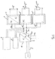
- the light source is a gas discharge lamp 5, which is controlled by an electric ballast (ECG) 1 as a control gear.
- ECG electric ballast
- this electronic ballast 1 has a rectifier 2 with power factor correction circuit (PFC, Power Factor Correction), an electrolyte storage capacitor 4 and an RF inverter 3, which in turn controls the gas discharge lamp 5 via its output circuit 6.
- PFC power factor correction circuit
- RF inverter 3 which in turn controls the gas discharge lamp 5 via its output circuit 6.
- the DC voltage (bus voltage) is therefore only present within the ECG.
- an emergency lighting control 7 may be provided.
- the rectifier 2 in the electronic ballast 1 is usually supplied with alternating voltage 9, for example mains voltage.
- each lamp operating device ECG 1
- PFC circuit Such a PFC circuit is known to reduce spurious harmonics in the input current.
- these inverters with PFC 2 provided locally in each ECG 1 represent a considerable cost factor, which severely restricts the trend towards extremely cost-effectively manufactured electronic ballasts.
- the starting point for the present invention is to propose control for illuminant operating devices, which enables more cost-effective production of operating devices.
- the central point of the invention is that the unit rectifier / PFC is no longer provided locally in each operating device, but centrally for several operating devices.
- the connection between this central unit and the individual operating devices takes place according to the invention via a DC output circuit.
- the present invention is concerned with the aspect of using a central cascaded AC / DC converter in a central processing unit.
- This converter can flexibly a variety of Provide output voltages for operating bulbs.
- a method for controlling lighting device operating devices by means of a central rectifier / PFC unit is provided.
- This central unit supplies at least one light source operating device by means of at least one DC output circuit.
- the DC output circuit enables unidirectional or bidirectional communication between the central unit and the lamp control gear.
- the central unit for load adaptation of the DC output circuit has a central AC / DC converter, which is constructed from a plurality of parallel-connected PFC modules, which are preceded by a rectifier.
- the PFC modules can feed at least one cascaded DC / DC converter, which consists of differently interconnectable converter modules and can provide different output voltages.
- At least one cascaded DC / DC converter can be used for central dimming of the lamp control gear.
- At least two converter modules can be connected in parallel.
- the individual converter modules may have different input voltages.
- the individual converter modules can be activated and deactivated.
- the switch-on period or the switch-on frequency of the individual converter modules can vary.
- the PFC modules or the converter modules can be identical and designed as plug-in modules.
- At least one parallel-connected converter module and / or at least one PFC module connected in parallel can serve as a redundant module.
- a redundant module can replace a failed module.
- the replacement for changing the output voltage of the DC output circuit can be carried out and carried out automatically or manually.
- a PFC module and a fuse module can be provided per string.
- a control system for lighting devices has a central rectifier / PFC unit, which supplies at least one lighting device by means of at least one DC output circuit.
- the DC output circuit enables unidirectional or bidirectional communication between the central unit and the lamp control gear.
- a central AC / DC converter having a plurality of parallel-connected PFC modules for load matching the DC output circuit in the central unit, which is preceded by a rectifier, is used.
- a central unit 18 comprising a rectifier 2 and a power factor correction circuit (PFC) 10 is provided for a plurality of light-emitting devices 1, 1 ', 1 ".
- the central unit 18 is supplied with alternating voltage 9.
- the central unit 18 is otherwise the same spatially separated from the control gear and can, for example, be centrally located for a room, a floor or even a building in a cabinet, etc.
- the various lamps operating devices 1, 1 ', 1'' a variety of light sources, such as a gas discharge lamp 5, LEDs 5', etc. control.
- the lamps can therefore be operated with DC or AC voltage, in the latter case, an inverter is provided in the associated operating device.
- a light sensor 5 '' or a motion detector may be connected to the output circuit 11 of the central unit 18.
- the operating devices 1, 1', 1" are designed differently.
- the corresponding operating device 3 is, for example, designed as a ballast with an inverter.
- the operating devices can also be referred to as "output converters".
- an output circuit 11 may be configured like a bus, so that starting from this central common bus 11, the various operating devices 1, 1 ', 1''via stubs 13, 13', 13 '' are supplied.
- individual output circuits 12 may be provided for individual operating devices or jointly supplied groups of operating devices.
- This DC output circuit 11, 12 has the advantage that it is less susceptible to parasitic effects compared to corresponding AC circuits.
- Emergency lighting control units 7 or further control units 8 can be connected to the DC output circuit 11 or 12, and these devices can also read signals from the connected operating devices from the DC bus if they have a powerline demodulator.
- the central unit 18 is provided in common for several operating devices, wherein the central unit is connected to the operating devices by means of at least one DC output circuit 11, 12.
- the voltage on the output circuit 11 may be, for example, 400 volts DC.
- FIG. 3 a central supply unit 18 according to an embodiment of the present invention is shown.
- the central power supply unit 18 consists of a rectifier 2 and a plurality of PFCs having central cascaded AC / DC converter 19th
- the illustrated central supply unit 18 is composed of three PFC units 14, 14 ', 14 "and three Fuse units 15, 15 ', 15''constructed. Further, the power factor correction circuits 14 14 '14 "are arranged in parallel.
- the central unit 18 has as many PFC units as strands 16, 16 ', 16'', so that each individual strand is a PFC unit 14, 14', 14 '' and then a fuse unit 15, 15 ', 15''contains.
- the electronic output fuses 15, 15 ', 15' ' serve to ensure a galvanic isolation between the supply unit 18 and the respective outputs 17, 17', 17 '', which feed the DC output circuits 11, 12.
- the central cascaded AC / DC converter 19 is also decoupled from the current flowing in the DC output circuits 11, 12.
- a PFC module 14 "serves as a redundant circuit, so that if necessary another PFC module can be replaced.
- the redundant PFC module 14 "then takes over the output supply if a module 14, 14 'of the central cascaded converter 19 fails. The transfer can be done either automatically or manually.
- a supply unit 18 offers a plurality of output stages.
- the individual output stages can feed different output circuits.
- the outputs 17, 17 ', 17'' may therefore have different output voltages, such as 400V, 12V and 120V.
- the modules of the central unit 18-including the redundant module (s) -which carry out the same function are identical and, for example, designed as plug-in modules.
- the PFC circuits 14, 14 ', 14 "of the central cascaded AC / DC converter become 19 designed as identical plug-in modules. In this way, these modules can be replaced.
- the size of the central supply unit 18 depends on the requirements per fire section or the space required per sub-distributor and a convenient wiring of the installation.
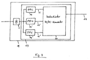
- the Fig. 4 shows a further embodiment of the invention.
- the central unit 18 is constructed of a rectifier 2 and a central cascaded AC / DC converter 19. Within the central cascaded converter 19 are three strands 16, 16 ', 16''. Each strand is connected to a PFC module 14, 14 ', 14''. Besides, as in Fig. 3 already explained, the central unit 18 per strand even a backup module 15, 15 ', 15''occupy.
- the PFC modules are connected to inputs of a cascaded DC / DC converter 20 having at least one output 17.
- the cascaded DC / DC converter 20 includes a plurality of converter modules and can respond to different load conditions by means of different switch-on cycles and disconnection or connection of converter modules.
- the Fig. 5 an embodiment of the cascaded DC / DC converter 20 with three converter modules 35, 35 ', 35''.
- the three converters are connected in parallel according to the invention and can be designed, for example, with half-bridge through-converters 35, 35 ', 35 ".
- Both switches 23 and 24 are switched on and off simultaneously with a pulse width modulated voltage.
- the voltage of an inductance 27 is equal to the input voltage V in of the converter module 35.
- This voltage V 28 charges an output capacitor 33 via a throttle 32.
- the demagnetization takes essentially as much time as the magnetization. Therefore, this switch-off phase of the switches 23, 24 must last at least as long as the switch-on.
- the maximum duty ratio t 1 / T of the converter module must therefore not be higher than 50%, where t 1 and T represent the duration of a switch-on phase or an entire period, ie two successive switch-on and switch-off phases.
- Fig. 5 shows Fig. 5 three parallel converter modules 35, 35 ', 35'', which form a cascaded DC / DC converter 20.
- the converter modules are turned on and off by the control of the respective diodes 23/24, 23 '/ 24' and 23 '' / 24 ''.
- At most one converter module is switched on at any one time.
- each converter module 35, 35 ', 35' ' periodically assigned a time slot in which it may be turned on.
- the three converter modules can alternatively be switched on and off in the same sequence.
- the three converter modules are cyclically switched on and off one after the other, so that each time slot T p is assigned to each successively, in which the respective module may be turned on.
- the maximum switch-on period of a converter module is thus at most the time period T p .
- the other two modules may be switched on for a time 2 * T p . Therefore, the duty ratio can not be higher than 33%, which ensures the demagnetization of the respective transformers 27-28, 27'-28 ', 27 "-28".
- a converter module 35 can serve to provide redundancy and take over the supply of the output stage if a converter module 35, 35 'fails
- Fig. 6 is a timing diagram of the output voltage V out of the cascaded DC / DC converter 20 and the output 17 of the central unit 18.
- different converter modules 35, 35 ', 35'' are activated and different duty cycles used.
- the modules 35, 35 ', 35 "are switched on and off with the same duty cycle.
- phase 1 only one module 35 is activated. This means that only this one on and off, leaving the other modules off.
- phase 2 and 3 two modules 35, 35 'or three modules 35, 35', 35 '' are activated in each case.
- the central processing unit 18 is able to compensate for different load conditions by activating and deactivating individual modules.
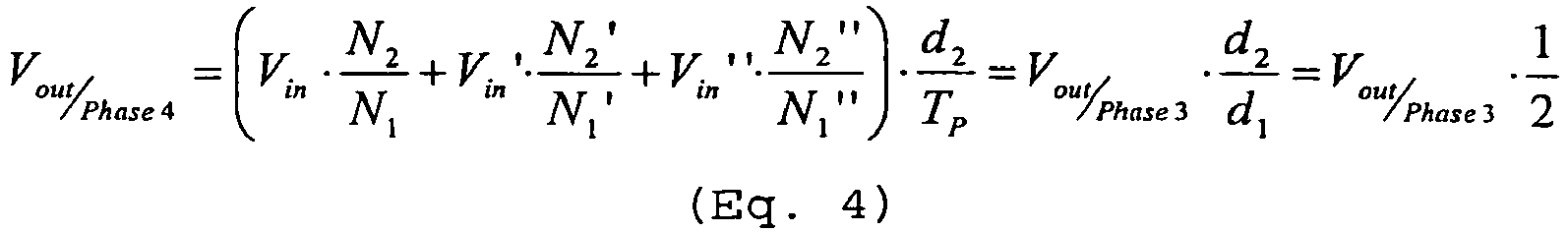
- Phase 4 differs from phases 1 to 3 in that the duration d 2 of a switch-on phase of a module is changed.
- An adaptation to the load state can also be done by changing the module turn-on time.
- Fig. 7 the input voltages of the cascaded DC / DC converter 20 are shown, depending on the activation and deactivation state of the individual converter modules 35, 35 ', 35''.
- the different modules have different DC input voltages, eg 700V, 600V and 500V.
- a module is deactivated when its input voltage is set to zero.
- phase 1 and 3 the duty cycle remains constant, so that the influence of the number of activated modules can be analyzed.
- a module 35 is activated.
- the output voltage V out then forms the mean value of this voltage V 31 .
- V / phase 1 out V in ⁇ N 2 N 1 ⁇ d 1 T P where d 1 / T p determines the duty cycle of turning a module on and off.
- the cascaded DC / DC converter 20 offer several different output voltages V out .
- the central supply unit 18 can adapt to the load of the connected bulbs.
- Fig. 8 shows a timing diagram of the control voltages V s , V s 'and V s ''of the respective modules 35, 35', 35 '' of the cascaded DC / DC converter 20.
- the output voltages V out can thus also be adapted by changing the switch-on duration d 1 of the modules.
Landscapes
- Engineering & Computer Science (AREA)
- Power Engineering (AREA)
- Dc-Dc Converters (AREA)
Description
Die vorliegende Erfindung bezieht sich auf die Steuerung von mehreren Leuchtmittel-Betriebsgeräten ausgehend von einer zentralen Einheit.The present invention relates to the control of a plurality of illuminant operating devices from a central unit.
Dabei geht die Erfindung von einem in
Zusätzlich kann eine Notbeleuchtungssteuerung 7 vorgesehen sein.In addition, an
Der Gleichrichter 2 in dem EVG 1 wird üblicherweise mit Wechselspannung 9, beispielsweise Netzspannung, versorgt.The
Gleichzeitig ist es bekannt, das EVG 1 über eine Digital- oder Analogbussteuerung 8 anzusteuern, um somit die Lampe 5 zu starten, zu dimmen oder auszuschalten. Festzuhalten ist, dass bei diesem Stand der Technik in jedem Lampenbetriebsgerät (EVG 1) ein eigener Gleichrichter 2 mit PFC-Schaltung vorgesehen ist. Eine derartige PFC-Schaltung verringert bekanntlich störende Oberwellen im Eingangsstrom. Andererseits stellen diese lokal in jedem EVG 1 vorgesehenen Wechselrichter mit PFC 2 einen beträchtlichen Kostenfaktor dar, der den Trend zu äußerst kostengünstig gefertigten EVG's stark eingrenzt.At the same time, it is known to control the
In der in 2002 vom IEEE Institut herausgegebenen wissenschaftlichen Veröffentlichung "Analysis and Design of a Modular, High Power Converter with High Efficiency for Electrical Power Distribution Systems" beschreibt L. Heinemann einen modularen Hochleistungs-Konverter, der aus drei gängigen Konverter-Modulen besteht, wobei jedes Modul aus einem Hochfrequenz-Transformator mit hoher Isolierungsfähigkeit aufgebaut ist. Der Konverter erlaubt eine redundante Arbeitsweise beim Ausfall eines Moduls. Ferner garantiert die modulare Struktur des Konverters eine einfache und schnelle Anpassung an unterschiedliche Spannungen mit unterschiedlichen Leistungs-/Frequenz-Werten.In the 2002 published by the IEEE Institute scientific publication "Analysis and Design of a Modular, High Power Converter with High Efficiency for Electrical Power Distribution Systems" L. Heinemann describes a modular high-performance converter consisting of three popular converter modules, where Each module is constructed from a high frequency transformer with high isolation capability. The converter allows redundant operation in case of failure of a module. Furthermore, the converter's modular structure ensures easy and fast adaptation to different voltages with different power / frequency values.
Die Dokumente
Ausgangspunkt für die vorliegende Erfindung ist es dementsprechend, eine Ansteuerung für Leuchtmittel-Betriebsgeräte vorzuschlagen, die eine kostengünstigere Fertigung von Betriebsgeräten ermöglicht.Accordingly, the starting point for the present invention is to propose control for illuminant operating devices, which enables more cost-effective production of operating devices.
Zentraler Punkt der Erfindung ist es dabei, dass die Einheit Gleichrichter/PFC nicht mehr lokal in jedem Betriebsgerät, sondern zentral für mehrere Betriebsgeräte vorgesehen ist. Die Verbindung zwischen dieser Zentraleinheit und den einzelnen Betriebsgeräten erfolgt erfindungsgemäß über einen DC-Ausgangskreis.The central point of the invention is that the unit rectifier / PFC is no longer provided locally in each operating device, but centrally for several operating devices. The connection between this central unit and the individual operating devices takes place according to the invention via a DC output circuit.
Insbesondere beschäftigt sich die vorliegende Erfindung mit dem Aspekt, einen zentralen kaskadierten AC/DC Konverter in einer Zentraleinheit einzusetzen. Dieser Konverter kann in flexibler Weise eine Vielzahl von Ausgangsspannungen zum Betreiben von Leuchtmitteln bereitstellen.In particular, the present invention is concerned with the aspect of using a central cascaded AC / DC converter in a central processing unit. This converter can flexibly a variety of Provide output voltages for operating bulbs.
Genauer gesagt wird die oben angeführte Aufgabe durch die Merkmale der unabhängigen Ansprüche gelöst. Die abhängigen Ansprüche entwickeln den zentralen Gedanken der Erfindung in besonders vorteilhafter Weise weiter.More specifically, the above object is solved by the features of the independent claims. The dependent claims further develop the central idea of the invention in a particularly advantageous manner.
Gemäss einem ersten Aspekt der vorliegenden Erfindung ist ein Verfahren zur Steuerung von Leuchtmittel-Betriebsgeräten mittels einer zentralen Gleichrichter/PFC-Einheit vorgesehen. Diese Zentraleinheit versorgt mittels wenigstens eines DC-Ausgangskreises wenigstens ein Leuchtmittel-Betriebsgerät. Der DC-Ausgangskreis ermöglicht eine uni- oder bidirektionale Kommunikation zwischen der Zentraleinheit und den Leuchtmittel-Betriebsgeräten. Erfindungsgemäß weist die Zentraleinheit zur Lastanpassung des DC-Ausgangskreises einen zentralen AC/DC Konverter auf, der aus mehreren parallel geschalteten PFC-Modulen aufgebaut ist, denen ein Gleichrichter vorgeschaltet ist.According to a first aspect of the present invention, a method for controlling lighting device operating devices by means of a central rectifier / PFC unit is provided. This central unit supplies at least one light source operating device by means of at least one DC output circuit. The DC output circuit enables unidirectional or bidirectional communication between the central unit and the lamp control gear. According to the invention, the central unit for load adaptation of the DC output circuit has a central AC / DC converter, which is constructed from a plurality of parallel-connected PFC modules, which are preceded by a rectifier.
Hierfür können die PFC-Module wenigstens einen kaskadierten DC/DC Konverter speisen, der aus unterschiedlich miteinander verschaltbaren Konverter-Modulen besteht und unterschiedliche Ausgangsspannungen bereitstellen kann.For this purpose, the PFC modules can feed at least one cascaded DC / DC converter, which consists of differently interconnectable converter modules and can provide different output voltages.
Wenigstens ein kaskadierter DC/DC-Konverter kann zur zentralen Dimmung der Leuchtmittel-Betriebsgeräte eingesetzt werden.At least one cascaded DC / DC converter can be used for central dimming of the lamp control gear.
Dabei können wenigstens zwei Konverter-Module parallel geschaltet sein.In this case, at least two converter modules can be connected in parallel.
Die einzelne Konverter-Module können unterschiedliche Eingangsspannungen aufweisen.The individual converter modules may have different input voltages.
Außerdem können die einzelne Konverter-Module aktiviert und deaktiviert werden können.In addition, the individual converter modules can be activated and deactivated.
Dabei kann die Einschalt-Zeitdauer oder die Einschalt-Frequenz der einzelnen Konverter-Module variieren.In this case, the switch-on period or the switch-on frequency of the individual converter modules can vary.
Die PFC-Module bzw. die Konverter-Module können identisch sein und als Steckmodule ausgeführt werden.The PFC modules or the converter modules can be identical and designed as plug-in modules.
Wenigstens ein parallel geschaltetes Konverter-Modul und/oder wenigstens ein parallel geschaltetes PFC-Modul können als Redundant-Modul dienen.At least one parallel-connected converter module and / or at least one PFC module connected in parallel can serve as a redundant module.
Ein Redundant-Modul kann ein ausgefallenes Modul ersetzen. Dabei kann das Ersetzen zur Änderung der Ausgangsspannung des DC-Ausgangskreises ausgeführt werden und automatisch oder manuell erfolgen.A redundant module can replace a failed module. In this case, the replacement for changing the output voltage of the DC output circuit can be carried out and carried out automatically or manually.
In der Zentraleinheit können pro Strang ein PFC-Modul und ein Sicherungs-Modul vorgesehen werden.In the central unit, a PFC module and a fuse module can be provided per string.
Gemäss einem weiteren Aspekt der vorliegenden Erfindung ist ein Steuersystem für Leuchtmittel-Betriebsgeräte vorgesehen. Das Steuersystem weist eine zentrale Gleichrichter/PFC-Einheit auf, die mittels wenigstens eines DC-Ausgangskreises wenigstens ein Leuchtmittel-Betriebsgerät versorgt. Der DC-Ausgangskreis ermöglicht eine uni- oder bidirektionale Kommunikation zwischen der Zentraleinheit und den Leuchtmittel-Betriebsgeräten. Erfindungsgemäß wird ein zentraler AC/DC Konverter aufweisend mehrere parallel geschalteten PFC-Modulen zur Lastanpassung des DC-Ausgangskreises in der Zentraleinheit, denen ein Gleichrichter vorgeschaltet ist, eingesetzt.According to a further aspect of the present invention, a control system for lighting devices is provided. The control system has a central rectifier / PFC unit, which supplies at least one lighting device by means of at least one DC output circuit. The DC output circuit enables unidirectional or bidirectional communication between the central unit and the lamp control gear. According to the invention, a central AC / DC converter having a plurality of parallel-connected PFC modules for load matching the DC output circuit in the central unit, which is preceded by a rectifier, is used.
Weitere Merkmale, Vorteile und Eigenschaften der vorliegenden Erfindung sollen nunmehr unter Bezugnahme auf die Figuren der beigefügten Zeichnungen sowie die folgende detaillierte Beschreibung von Ausführungsbeispielen der Erfindung näher erläutert werden.
- Fig. 1
- zeigt eine schematische Ansicht eines erfindungsgemäßen Steuersystems für Leuchtmittel-Betriebsgeräte mit zentraler Gleichrichter/PFC-Einheit und DC-Ausgangskreis,
- Fig. 2
- zeigt eine aus dem Stand der Technik bekannte Betriebsmittel-Ausgestaltung für Gasentladungslampen,
- Fig. 3
- zeigt eine Zentraleinheit aufweisend einen aus PFC-Modulen ausgebildeten zentralen kaskadierten AC/DC Konverter und mehrere DC-Ausgangskreise gemäss einer Ausführungsform der vorliegenden Erfindung,
- Fig. 4
- zeigt eine Zentraleinheit aufweisend einen zentralen kaskadierten AC/DC Konverter, worin parallele PFC-Module einen kaskadierten DC/DC-Konverter speisen,
- Fig. 5
- zeigt einen detaillierten kaskadierten DC/DC-Konverter mit einem Ausgang,
- Fig. 6
- zeigt ein Zeitdiagramm der Ausgangsspannung der erfindungsgemäßen Zentraleinheit aufweisend den kaskadierten DC/DC-Konverter,
- Fig. 7
- zeigt ein Zeitdiagramm der Eingangsspannungen des kaskadierten DC/DC-Konverters,
- Fig. 8
- zeigt ein Zeitdiagramm der Steuerspannungen des kaskadierten DC/DC-Konverters,
- Fig. 1
- shows a schematic view of a control system according to the invention for light-emitting devices with central rectifier / PFC unit and DC output circuit,
- Fig. 2
- shows a known from the prior art equipment design for gas discharge lamps,
- Fig. 3
- shows a central unit comprising a central cascaded AC / DC converter formed from PFC modules and a plurality of DC output circuits according to an embodiment of the present invention,
- Fig. 4
- shows a central unit comprising a central cascaded AC / DC converter, wherein parallel PFC modules feed a cascaded DC / DC converter,
- Fig. 5
- shows a detailed cascaded DC / DC converter with an output,
- Fig. 6
- shows a timing diagram of the output voltage of the central unit according to the invention comprising the cascaded DC / DC converter,
- Fig. 7
- shows a timing diagram of the input voltages of the cascaded DC / DC converter,
- Fig. 8
- shows a timing diagram of the control voltages of the cascaded DC / DC converter,
Wie in
Wie in
Weiterhin können an den Ausgangskreis 11 der Zentraleinheit 18 auch andere (bspw. passive) lichttechnische oder Gebäudetechnische Einrichtungen, wie beispielsweise ein Lichtsensor 5'' oder ein Bewegungsmelder (nicht dargestellt) angeschlossen sein.Furthermore, other (eg passive) lighting technology or building services equipment, such as a light sensor 5 '' or a motion detector (not shown) may be connected to the
Je nach Natur der angeschlossenen Leuchtmittel 5, 5' bzw. Sensoren 5'' sind die Betriebsgeräte 1, 1', 1'' unterschiedlich ausgebildet. Für den Fall, dass die Gasentladungslampe 5 angesteuert werden soll, ist das entsprechende Betriebsgerät 3 bspw. als Vorschaltgerät mit einem Wechselrichter ausgebildet. Die Betriebsgeräte können in diesem Fall auch als "Ausgangs-Konverter" bezeichnet werden.Depending on the nature of the
Die Spannungsversorgung der Betriebsgeräte und Leuchtmittel wie auch die uni- oder bidirektionale Kommunikation zwischen der Zentraleinheit und den lokalen Betriebsgeräten 1, 1', 1'' erfolgt über wenigstens einen DC-Ausgangskreis 11, 12. Wie in
Dieser DC-Ausgangskreis 11, 12 hat den Vorteil, dass er im Vergleich zu entsprechenden AC-Kreisen gegenüber parasitären Effekten weniger anfällig ist.This
An den DC-Ausgangskreis 11 bzw. 12 können Notlicht-Steuereinheiten 7 bzw. weitere Steuereinheiten 8 angeschlossen sein, wobei diese Einrichtungen auch Signale von den angeschlossenen Betriebsgeräten aus dem DC-Bus auslesen könne, wenn sie einen Powerline-Demodulator aufweisen.Emergency
Festzuhalten ist also, dass gemäß der vorliegenden Erfindung die Zentraleinheit 18 für mehrere Betriebsgeräte gemeinsam vorgesehen ist, wobei die Zentraleinheit mit den Betriebsgeräten mittels wenigstens eines DC-Ausgangskreises 11, 12 verbunden ist. Die Spannung auf dem Ausgangskreis 11 kann beispielsweise 400 Volt DC betragen.It should be noted that according to the present invention, the
In
Die in
Die elektronischen Ausgangs-Sicherungen 15, 15', 15'' dienen dazu, eine galvanische Trennung zwischen der Versorgungseinheit 18 und den jeweiligen Ausgängen 17, 17', 17'', die die DC-Ausgangskreise 11, 12 speisen, zu gewährleisten. Somit ist auch der zentrale kaskadierte AC/DC Konverter 19 von dem in den DC-Ausgangskreisen 11, 12 fließenden Strom abgekoppelt.The electronic output fuses 15, 15 ', 15' 'serve to ensure a galvanic isolation between the
Erfindungsgemäß dient ein PFC-Modul 14'' als Redundant-Schaltung, so dass bei Bedarf ein anderes PFC-Modul ersetzen werden kann. Das Redundant-PFC-Modul 14'' übernimmt dann die Ausgang-Versorgung falls ein Modul 14, 14' des zentralen kaskadierten Konverters 19 ausfällt. Die Übernahme kann dabei entweder automatisch oder manuell erfolgen.According to the invention, a
In
Erfindungsgemäß sind die Module der Zentraleinheit 18 - einschließlich der oder die Redundant-Module -, die eine selbe Funktion ausführen, identisch und bspw. als Steckmodule ausgeführt. So werden z.B. die PFC-Schaltungen 14, 14', 14'' des zentralen kaskadierten AC/DC Konverters 19 als identisch angefertigte Steckmodule ausgeführt. Auf diese Weise, können diese Module ausgewechselt werden. Die Größe der zentralen Versorgungseinheit 18 richtet sich nach den Anforderungen pro Brandabschnitt bzw. dem Platzbedarf pro Unterverteiler und einer zweckmäßigen Verkabelung der Installation.According to the invention, the modules of the central unit 18-including the redundant module (s) -which carry out the same function are identical and, for example, designed as plug-in modules. For example, the
Die
Die PFC-Module werden an Eingänge eines kaskadierten DC/DC Konverters 20 angeschlossen, der wenigstens einen Ausgang 17 aufweist. Der kaskadierte DC/DC Konverter 20 beinhaltet mehrere Konverter-Module und kann durch unterschiedliche Einschaltzyklen und Ab- bzw. Zuschalten von Konverter-Modulen auf unterschiedliche Lastzustände reagieren.The PFC modules are connected to inputs of a cascaded DC /
Gemäss der vorliegenden Erfindung zeigt die
Folgende Beschreibung des Funktionsprinzips eines Konverter-Moduls 35 gilt auch für die anderen Konverter-Module 35', 35''.The following description of the operating principle of a
Beide Schalter 23 und 24 werden mit einer pulsbreitenmodulierten Spannung gleichzeitig ein- und ausgeschaltet.Both switches 23 and 24 are switched on and off simultaneously with a pulse width modulated voltage.
In der Einschaltphase der Schalter 23, 24 ist die Spannung einer Induktivität 27 gleich der Eingangsspannung Vin des Konverter-Moduls 35. Die Induktivität 27 ist die Primärwicklung (N1) eines Transformators 27, 28 und ist gleichsinnig mit der Sekundärwicklung 28 (N2) des Transformators gewickelt, so dass in der leitenden Phase an der Induktivität 28 die Spannung V28=Vin*N2/N1 anliegt. Diese Spannung V28 lädt einen Ausgangskondensator 33 über eine Drossel 32.In the switch-on phase of the
Während der Abschaltphase der Schalter 23, 24 fließt kein Strom durch die Induktivität 27 und damit auch nicht durch die Induktivität 28. Die Speicherdrossel 32 zieht ihren Strom über die Freilaufdiode 31. Während dieser Abschaltphase muss auch der magnetische Fluss im Transformator 27, 28 abgebaut werden. Dies wird über die Primärwicklung des Transformators 27, 28 ausgeführt: der wird nämlich über die Induktivität 27 und die primärseitigen Diode 21, 22 gegen die Eingangsspannung Vin entmagnetisiert.During the turn-off phase of the
Die Entmagnetisierung benötigt im wesentlichen so viel Zeit wie die Magnetisierung. Daher muss diese Abschaltphase der Schalter 23, 24 mindestens eben so lang dauern wie die Einschaltphase. Das maximale Tastverhältnis t1/T des Konverter-Moduls darf daher nicht höher als 50% sein, wobei t1 und T die Dauer einer Einschaltphase bzw. einer gesamten Periode, i.e. zwei aufeinanderfolgen Ein- und Ausschaltphasen, darstellen.The demagnetization takes essentially as much time as the magnetization. Therefore, this switch-off phase of the
Wird das Konverter-Modul 35 zyklisch ein- und ausgeschaltet und bleiben die Konverter 35' und 35" ausgeschaltet, so ist die Spannung V31 der Diode 31 eine pulsbreitenmodulierte Spannung, die zwischen den Werten Null und V28=Vin*N2/N1 springt. Der nachfolgende Tiefpass, gebildet aus einer Drossel 32 und einem Ausgangskondensator 33, bildet mit der Spannung Vout den Mittelwert dieser Spannung V31.If the
Erfindungsgemäß zeigt
In einer Ausführungsform der Erfindung wird zu jedem Zeitpunkt höchstens ein Konverter-Modul eingeschaltet. Um das zu gewährleisten, wird jedem Konverter-Modul 35, 35', 35'' periodisch einen Zeitschlitz zugewiesen, worin er eingeschaltet werden darf.In one embodiment of the invention, at most one converter module is switched on at any one time. To ensure this, each
Dazu können die drei Konverter-Module alternativ und in der selben Reihenfolge ein- und ausgeschaltet werden. Erfindungsgemäß werden die drei Konverter-Module nacheinander zyklisch ein- und ausgeschaltet, so dass jedem nacheinander einen Zeitschlitz Tp zugewiesen wird, worin das jeweilige Modul angeschaltet werden darf. Die maximale Einschalt-Zeitdauer eines Konverter-Moduls beträgt also höchstens die Zeitdauer Tp. Danach dürfen für eine Zeit 2*Tp ausschließlich die zwei andere Module eingeschaltet werden. Daher kann das Tastverhältnis nicht höher als 33% sein, was die Entmagnetisierung der jeweiligen Transformatoren 27-28, 27'-28', 27''-28'' sichert.For this purpose, the three converter modules can alternatively be switched on and off in the same sequence. According to the invention, the three converter modules are cyclically switched on and off one after the other, so that each time slot T p is assigned to each successively, in which the respective module may be turned on. The maximum switch-on period of a converter module is thus at most the time period T p . Thereafter, only the other two modules may be switched on for a
Werden die Konverter-Module 35, 35', 35'' nacheinander ein-/ und ausgeschaltet, so kann die Spannung V31 der Diode 31 je nach Zeitschlitz zwischen den folgenden Werten springen: Null und V28=Vin*N2/N1, Null und V28'=Vin'*N2'/N1', oder Null und V28''=Vin''*N2''/N1''. Da die Ausgangsspannung Vout den Mittelwert der Spannung V31 bildet, kann sie durch Änderung der Einschaltzeit-Dauer und durch Deaktivierung der jeweiligen Konverter-Module an unterschiedliche Lastzustände angepasst werden. Diese stellbare Ausgangsspannung ermöglicht auch eine zentrale Dimmung der angeschlossenen Lichtmittel.If the
Ein Konverter-Modul 35'' kann übrigens zur Redundanzbereitstellung dienen und die Versorgung der Ausgangstufe übernehmen, falls ein Konverter-Modul 35, 35' ausfälltIncidentally, a
In Phase 1 wird nur ein Modul 35 aktiviert. Das bedeutet, dass nur dieses ein-/ und ausgeschaltet und dabei die anderen Module ausgeschaltet bleiben. In Phase 2 und 3 werden jeweils zwei Module 35, 35' bzw. drei Module 35, 35', 35'' aktiviert. Wie ersichtlich wird, ist die Zentraleinheit 18 in der Lage, durch Aktivieren und Deaktivieren einzelner Module unterschiedliche Lastzustände zu kompensieren.In
Die Phase 4 unterscheidet sich von den Phasen 1 bis 3, in dem die Zeitdauer d2 einer Einschaltphase eines Moduls verändert wird. Eine Anpassung an den Lastzustand kann dadurch auch durch Änderung der Modul-Einschalt-Zeitdauer erfolgen.
In
In Phase 1, 2 und 3 bleibt das Tastverhältnis konstant, so dass der Einfluss der Anzahl der aktivierten Module analysiert werden kann. In der ersten Phase 1 wird ein Modul 35 aktiviert. Demzufolge wird die Spannung V31 der Diode 31 eine pulsbreitenmodulierte Spannung, die zwischen den Werten Null und V28=Vin*N2/N1 springt. Die Ausgangsspannung Vout bildet dann den Mittelwert dieser Spannung V31. Für den kontinuierlichen Betrieb, bei dem der Strom durch die Drossel 32 nie Null wird, gilt daher: ![]()
![]()
In Phase 2 wird außer dem Modul 35 noch das Modul 35' aktiviert. Da die Module nicht gleichzeitig eingeschaltet werden springt diesmal die Spannung V31 zwischen den Werten Null, V28=Vin*N2/N1 und V28'=Vin'*N2'/N1'. Die Ausgangsspannung bildet dann dessen Mittelwert: 
Beim Aktivieren von mehr oder weniger Konverter-Modulen, die mit unterschiedlichen Eingangsspannungen versorgt werden können, kann demzufolge der kaskadierte DC/DC-Konverter 20 mehrere verschiedene Ausgangsspannungen Vout anbieten. Somit kann sich die zentrale Versorgungseinheit 18 an die Last der angeschlossenen Leuchtmittel anpassen.When activating more or fewer converter modules that can be supplied with different input voltages, therefore, the cascaded DC /

Die Ausgangsspannungen Vout kann somit auch durch Änderung der Einschalt-Zeitdauer d1 der Module angepasst werden.The output voltages V out can thus also be adapted by changing the switch-on duration d 1 of the modules.
Gemäss einem weiteren Aspekt der Erfindung wird die Ausgangsspannungen Vout durch Änderung der Taktfrequenz fP=1/TP angepasst.According to a further aspect of the invention, the output voltages V out are adjusted by changing the clock frequency f P = 1 / T P.
Folgende Tabelle fasst die Bezugszeichen der Figuren zusammen:
Claims (20)
- A method for the control of operating devices for lighting means (1, 1', 1") by means of a central rectifier/power factor correction (PFC)-unit as central unit (18), which by means of at least one DC-output circuit (11) supplies the operating devices for lighting means (1, 1', 1"), wherein the DC-output circuit (11) enables a uni- or bi-directional communication between the central unit (18) and the operating devices for lighting means (1, 1', 1"),
characterized in
that the central unit (18) comproses for load adaptation of the DC-output circuit (11) a central cascaded AC/DC converter (19), which is made up of several PFC-modules (14, 14', 14") connected in parallel, to which a rectifier (2) is upstream. - A method according to Claim 1,
characterized in
that the PFC-module (14, 14', 14") supplies at least one cascaded DC/DC converter (20), which consists of converter-modules (35, 35', 35") combined differently with each other and provides different output voltages. - A method according to Claim 2,
characterized in
that at least one of the cascaded DC/DC converters (20) is used for the central dimming of the operating devices for lighting means. - A method according to Claim 2,
characterized in
that at least two converter modules (35, 35', 35") are connected in parallel. - A method according to Claim 2
characterized in
that the individual converter modules (35, 35', 35") have different input voltages. - A method according to Claim 2,
characterized in
that the individual converter-modules (35, 35', 35") are activated and deactivated. - A method according to Claim 2,
characterized in
that the switch-on-duration and/or the switch-on-frequency of the individual converter modules (35, 35', 35") is adjustable. - A method according to Claim 2,
characterized in
that the PFC-modules (14, 14', 14") or the converter-modules (35, 35', 35") are identical and are designed as plug-in modules. - A method according to Claim 2,
characterized in
that at least one converter-module (35, 35', 35") connected in parallel and/or at least one PFC-module (14, 14', 14") connected in parallel serves as a redundant-module. - A method according to Claim 2,
characterized in
that one PFC-module (14, 14', 14") and one security-module (15, 15', 15") are provided per string (16, 16', 16") in the central unit (18). - A control system for operating devices for lighting means (1, 1', 1") and operating devices for lighting means (1, 1', 1"),
wherein the control system has a central rectifier/power factor correction (PFC)-unit as central unit (18), which supplies the operating devices for lighting means (1, 1', 1") by means of at least one DC-output circuit (11),
wherein the DC-output circuit (11) enables a uni- or bi-directional communication between the central unit (18) and the operating devices for lighting means (1, 1', 1"),
characterized by
a central cascaded AC/DC converter (19) having several PFC-modules (14, 14', 14") connected in parallel for load adaptation of the DC output circuit (11) in the central unit (18), to which a rectifier (2) is upstream. - A control system for operating devices for lighting means and operating devices for lighting means according to Claim 11,
characterized in
that at least one of the cascaded DC/DC converters (20) made up of converter-modules (35, 35', 35") combined differently with each other are supplied by the PFC-modules (14, 14', 14"). - A control system for operating devices for lighting means and operating devices for lighting means according to Claim 12,
characterized in
that the cascaded DC/DC converters (20) provide different output voltages. - A control system for operating devices for lighting means and operating devices for lighting means according to Claim 12,
characterized in
that at least one of the cascaded DC/DC converters (20) is used for the central dimming of the operating devices for lighting means. - A control system for operating devices for lighting means and operating devices for lighting means according to Claim 12,
characterized in
that at least two converter-modules (35, 35', 35") are connected in parallel. - A control system for operating devices for lighting means and operating devices for lighting means according to Claim 12,
characterized in
that the individual converter-modules (35, 35', 35") have different input voltages. - A control system for operating devices for lighting means and operating devices for lighting means according to Claim 12,
characterized in
that the individual converter-modules (35, 35', 35") have an adjustable switch-on-duration and/or switch-on-frequency. - A control system for operating devices for lighting means and operating devices for lighting means according to Claim 12,
characterized in
that the PFC-modules (14, 4', 14") or the converter-modules (35, 35', 35") are identical and are designed as plug-in modules. - A control system for operating devices for lighting means and operating devices for lighting means according to Claim 12,
characterized in
that at least one converter-module (35, 35', 35") connected in parallel and/or at least one PFC-module (14, 14', 14") connected in parallel serves as a redundant-module. - A control system for operating devices for lighting means and operating devices for lighting means according to Claim 12,
characterized in
that a PFC-module (14, 14', 14") and a security module (15, 15', 15") are provided per central unit-string (16, 16', 16").
Applications Claiming Priority (2)
| Application Number | Priority Date | Filing Date | Title |
|---|---|---|---|
| DE102004012215 | 2004-03-12 | ||
| DE102004012215.6A DE102004012215B4 (en) | 2004-03-12 | 2004-03-12 | Control of illuminant control gear with a central cascaded AC / DC converter |
Publications (2)
| Publication Number | Publication Date |
|---|---|
| EP1583402A1 EP1583402A1 (en) | 2005-10-05 |
| EP1583402B1 true EP1583402B1 (en) | 2016-08-03 |
Family
ID=34877595
Family Applications (1)
| Application Number | Title | Priority Date | Filing Date |
|---|---|---|---|
| EP05000692.3A Not-in-force EP1583402B1 (en) | 2004-03-12 | 2005-01-14 | Control of lighting devices with a central AC/DC cascaded converter |
Country Status (2)
| Country | Link |
|---|---|
| EP (1) | EP1583402B1 (en) |
| DE (1) | DE102004012215B4 (en) |
Families Citing this family (6)
| Publication number | Priority date | Publication date | Assignee | Title |
|---|---|---|---|---|
| US8400070B2 (en) | 2007-07-30 | 2013-03-19 | Osram Gesellschaft Mit Beschraenkter Haftung | Electronic ballast and method for operating at least one discharge lamp |
| DE102014215312A1 (en) * | 2014-08-04 | 2016-02-04 | Robert Bosch Gmbh | Control device for an air conditioning device |
| CN104578376B (en) * | 2015-01-31 | 2017-01-04 | 华为技术有限公司 | A kind of communication power supply |
| SG11201706701SA (en) * | 2015-03-31 | 2017-10-30 | Mitsubishi Electric Corp | Power supply device and air conditioner |
| CN109802420B (en) * | 2019-01-28 | 2021-01-12 | 北京四方继保自动化股份有限公司 | Flexible direct-current high-frequency resonance suppression method based on voltage feedforward nonlinear filtering |
| CN110381642A (en) * | 2019-08-07 | 2019-10-25 | 深圳市智童乐慧科技有限公司 | A kind of splicing lamp |
Citations (1)
| Publication number | Priority date | Publication date | Assignee | Title |
|---|---|---|---|---|
| EP1501176A2 (en) * | 2003-07-24 | 2005-01-26 | Harman International Industries, Incorporated | Power supply with power factor correction |
Family Cites Families (8)
| Publication number | Priority date | Publication date | Assignee | Title |
|---|---|---|---|---|
| DE19502772C2 (en) * | 1995-01-30 | 2002-02-28 | Walter Holzer | Electronic ballast for fluorescent lamps |
| FR2761564B1 (en) * | 1997-03-27 | 2001-07-27 | Jacques Emile Boudan | SYSTEM AND APPARATUS FOR SUPPLYING THE DISCHARGE LAMPS OF A LIGHTING NETWORK |
| JP2002539590A (en) * | 1999-03-11 | 2002-11-19 | パワー・サーキット・イノベーションズ・インコーポレーテッド | Networkable power controller |
| AU2002212004A1 (en) * | 2000-10-12 | 2002-04-22 | Photoscience Japan Corporation | Discharge lamps preheating |
| IT1316561B1 (en) * | 2000-12-28 | 2003-04-22 | Setech S R L | FEEDING DEVICE FOR COLD CATHODE LAMPS. |
| DE10117372B4 (en) * | 2001-04-06 | 2006-11-09 | Siemens Ag | Protective device, protective device and protection method for an electric cable |
| KR100840933B1 (en) * | 2002-01-31 | 2008-06-24 | 삼성전자주식회사 | Apparatus for driving lamp and liquid crystal display with the same |
| AU2003233166A1 (en) * | 2002-06-03 | 2003-12-19 | Rafael Mogilner | Multiple channel ballast and networkable topology and system including power line carrier applications |
-
2004
- 2004-03-12 DE DE102004012215.6A patent/DE102004012215B4/en not_active Expired - Fee Related
-
2005
- 2005-01-14 EP EP05000692.3A patent/EP1583402B1/en not_active Not-in-force
Patent Citations (1)
| Publication number | Priority date | Publication date | Assignee | Title |
|---|---|---|---|---|
| EP1501176A2 (en) * | 2003-07-24 | 2005-01-26 | Harman International Industries, Incorporated | Power supply with power factor correction |
Also Published As
| Publication number | Publication date |
|---|---|
| EP1583402A1 (en) | 2005-10-05 |
| DE102004012215B4 (en) | 2020-03-26 |
| DE102004012215A1 (en) | 2005-09-29 |
Similar Documents
| Publication | Publication Date | Title |
|---|---|---|
| EP2596686B1 (en) | Dimmable led lamp | |
| EP2837264B1 (en) | Converter for a lamp, led converter, and converter operation method | |
| EP1583402B1 (en) | Control of lighting devices with a central AC/DC cascaded converter | |
| EP2219286A1 (en) | Switching assembly for converting an input alternating current into a direct current, retrofitting lamp with such a switching assembly and lighting system | |
| DE10030873A1 (en) | Illumination system has electronic transformation stage connected across energy supply line supplied by current supply stage for providing HF operating voltage for lamp | |
| WO2017046039A1 (en) | Pfc module for intermittent flow | |
| EP1555861B1 (en) | Control of lighting apparatusses through switching modulation on a DC-bus | |
| EP2278861B1 (en) | Central power supply having several DC output circuits | |
| EP1555858B1 (en) | Central power supply for lamp operation devices containing a central PFC/rectification device | |
| EP2591640B1 (en) | Control of operational parameters of operational devices for led's | |
| DE202006020298U1 (en) | Circuit arrangement for operating light sources or comparable loads in mains or emergency power operation | |
| EP1271745A1 (en) | Method for operation of an electric end-user as well as a device using such a method | |
| DE102014104365A1 (en) | lighting device | |
| WO2010040542A1 (en) | Driver circuit for a semiconductor light source (led) | |
| DE202016106926U1 (en) | Adjust the dead time of an LLC circuit | |
| WO2023134898A1 (en) | Output switching stage with glow avoidance | |
| DE102004012216B4 (en) | Control of illuminant control gear via a switchable DC bus | |
| DE102011050306B3 (en) | Inverter circuit of electronic ballast for gas discharge lamp, has three electronic switches that are connected in series, where branch node is provided between every two adjacent switches and are connected to lamp circuits | |
| WO2012116389A1 (en) | Change in operating mode of an operating device for light-emitting means | |
| DE102019107824A1 (en) | Power correction factor circuit for at least one lamp | |
| WO2003088719A1 (en) | Circuit arrangement for supplying light-emitting diodes | |
| AT513632B1 (en) | Lighting devices | |
| DE102004050110A1 (en) | Discharge lamp operating method for operating discharge lamps on single- or multiphase networks feeds a mains voltage to fluorescent lamp ballast/choke half-bridge drivers via a rectifier system | |
| EP3524037A1 (en) | Synchronous down-converter for operating one or more illuminants, associated method and operating unit | |
| DE102017113013A1 (en) | Operating device and method for operating a control gear |
Legal Events
| Date | Code | Title | Description |
|---|---|---|---|
| PUAI | Public reference made under article 153(3) epc to a published international application that has entered the european phase |
Free format text: ORIGINAL CODE: 0009012 |
|
| AK | Designated contracting states |
Kind code of ref document: A1 Designated state(s): AT BE BG CH CY CZ DE DK EE ES FI FR GB GR HU IE IS IT LI LT LU MC NL PL PT RO SE SI SK TR |
|
| AX | Request for extension of the european patent |
Extension state: AL BA HR LV MK YU |
|
| 17P | Request for examination filed |
Effective date: 20060118 |
|
| AKX | Designation fees paid |
Designated state(s): AT BE BG CH CY CZ DE DK EE ES FI FR GB GR HU IE IS IT LI LT LU MC NL PL PT RO SE SI SK TR |
|
| RAP1 | Party data changed (applicant data changed or rights of an application transferred) |
Owner name: TRIDONIC GMBH & CO KG |
|
| 17Q | First examination report despatched |
Effective date: 20110826 |
|
| REG | Reference to a national code |
Ref country code: DE Ref legal event code: R079 Ref document number: 502005015303 Country of ref document: DE Free format text: PREVIOUS MAIN CLASS: H05B0037020000 Ipc: H02M0001420000 |
|
| GRAP | Despatch of communication of intention to grant a patent |
Free format text: ORIGINAL CODE: EPIDOSNIGR1 |
|
| RIC1 | Information provided on ipc code assigned before grant |
Ipc: H02M 1/00 20060101ALN20160406BHEP Ipc: H02M 1/42 20070101AFI20160406BHEP Ipc: H05B 41/28 20060101ALI20160406BHEP Ipc: H02M 3/28 20060101ALI20160406BHEP |
|
| RIC1 | Information provided on ipc code assigned before grant |
Ipc: H02M 3/28 20060101ALI20160420BHEP Ipc: H02M 1/00 20060101ALN20160420BHEP Ipc: H05B 41/28 20060101ALI20160420BHEP Ipc: H02M 1/42 20070101AFI20160420BHEP |
|
| INTG | Intention to grant announced |
Effective date: 20160511 |
|
| GRAS | Grant fee paid |
Free format text: ORIGINAL CODE: EPIDOSNIGR3 |
|
| GRAA | (expected) grant |
Free format text: ORIGINAL CODE: 0009210 |
|
| AK | Designated contracting states |
Kind code of ref document: B1 Designated state(s): AT BE BG CH CY CZ DE DK EE ES FI FR GB GR HU IE IS IT LI LT LU MC NL PL PT RO SE SI SK TR |
|
| REG | Reference to a national code |
Ref country code: GB Ref legal event code: FG4D Free format text: NOT ENGLISH |
|
| REG | Reference to a national code |
Ref country code: AT Ref legal event code: REF Ref document number: 817907 Country of ref document: AT Kind code of ref document: T Effective date: 20160815 Ref country code: CH Ref legal event code: EP |
|
| REG | Reference to a national code |
Ref country code: IE Ref legal event code: FG4D Free format text: LANGUAGE OF EP DOCUMENT: GERMAN |
|
| REG | Reference to a national code |
Ref country code: DE Ref legal event code: R096 Ref document number: 502005015303 Country of ref document: DE |
|
| REG | Reference to a national code |
Ref country code: NL Ref legal event code: MP Effective date: 20160803 |
|
| REG | Reference to a national code |
Ref country code: LT Ref legal event code: MG4D |
|
| REG | Reference to a national code |
Ref country code: FR Ref legal event code: PLFP Year of fee payment: 13 |
|
| PG25 | Lapsed in a contracting state [announced via postgrant information from national office to epo] |
Ref country code: IS Free format text: LAPSE BECAUSE OF FAILURE TO SUBMIT A TRANSLATION OF THE DESCRIPTION OR TO PAY THE FEE WITHIN THE PRESCRIBED TIME-LIMIT Effective date: 20161203 Ref country code: IT Free format text: LAPSE BECAUSE OF FAILURE TO SUBMIT A TRANSLATION OF THE DESCRIPTION OR TO PAY THE FEE WITHIN THE PRESCRIBED TIME-LIMIT Effective date: 20160803 Ref country code: LT Free format text: LAPSE BECAUSE OF FAILURE TO SUBMIT A TRANSLATION OF THE DESCRIPTION OR TO PAY THE FEE WITHIN THE PRESCRIBED TIME-LIMIT Effective date: 20160803 Ref country code: NL Free format text: LAPSE BECAUSE OF FAILURE TO SUBMIT A TRANSLATION OF THE DESCRIPTION OR TO PAY THE FEE WITHIN THE PRESCRIBED TIME-LIMIT Effective date: 20160803 Ref country code: FI Free format text: LAPSE BECAUSE OF FAILURE TO SUBMIT A TRANSLATION OF THE DESCRIPTION OR TO PAY THE FEE WITHIN THE PRESCRIBED TIME-LIMIT Effective date: 20160803 |
|
| PG25 | Lapsed in a contracting state [announced via postgrant information from national office to epo] |
Ref country code: GR Free format text: LAPSE BECAUSE OF FAILURE TO SUBMIT A TRANSLATION OF THE DESCRIPTION OR TO PAY THE FEE WITHIN THE PRESCRIBED TIME-LIMIT Effective date: 20161104 Ref country code: PL Free format text: LAPSE BECAUSE OF FAILURE TO SUBMIT A TRANSLATION OF THE DESCRIPTION OR TO PAY THE FEE WITHIN THE PRESCRIBED TIME-LIMIT Effective date: 20160803 Ref country code: ES Free format text: LAPSE BECAUSE OF FAILURE TO SUBMIT A TRANSLATION OF THE DESCRIPTION OR TO PAY THE FEE WITHIN THE PRESCRIBED TIME-LIMIT Effective date: 20160803 Ref country code: SE Free format text: LAPSE BECAUSE OF FAILURE TO SUBMIT A TRANSLATION OF THE DESCRIPTION OR TO PAY THE FEE WITHIN THE PRESCRIBED TIME-LIMIT Effective date: 20160803 Ref country code: PT Free format text: LAPSE BECAUSE OF FAILURE TO SUBMIT A TRANSLATION OF THE DESCRIPTION OR TO PAY THE FEE WITHIN THE PRESCRIBED TIME-LIMIT Effective date: 20161205 |
|
| PG25 | Lapsed in a contracting state [announced via postgrant information from national office to epo] |
Ref country code: RO Free format text: LAPSE BECAUSE OF FAILURE TO SUBMIT A TRANSLATION OF THE DESCRIPTION OR TO PAY THE FEE WITHIN THE PRESCRIBED TIME-LIMIT Effective date: 20160803 Ref country code: EE Free format text: LAPSE BECAUSE OF FAILURE TO SUBMIT A TRANSLATION OF THE DESCRIPTION OR TO PAY THE FEE WITHIN THE PRESCRIBED TIME-LIMIT Effective date: 20160803 |
|
| REG | Reference to a national code |
Ref country code: DE Ref legal event code: R097 Ref document number: 502005015303 Country of ref document: DE |
|
| PG25 | Lapsed in a contracting state [announced via postgrant information from national office to epo] |
Ref country code: CZ Free format text: LAPSE BECAUSE OF FAILURE TO SUBMIT A TRANSLATION OF THE DESCRIPTION OR TO PAY THE FEE WITHIN THE PRESCRIBED TIME-LIMIT Effective date: 20160803 Ref country code: BG Free format text: LAPSE BECAUSE OF FAILURE TO SUBMIT A TRANSLATION OF THE DESCRIPTION OR TO PAY THE FEE WITHIN THE PRESCRIBED TIME-LIMIT Effective date: 20161103 Ref country code: BE Free format text: LAPSE BECAUSE OF NON-PAYMENT OF DUE FEES Effective date: 20170131 Ref country code: DK Free format text: LAPSE BECAUSE OF FAILURE TO SUBMIT A TRANSLATION OF THE DESCRIPTION OR TO PAY THE FEE WITHIN THE PRESCRIBED TIME-LIMIT Effective date: 20160803 Ref country code: SK Free format text: LAPSE BECAUSE OF FAILURE TO SUBMIT A TRANSLATION OF THE DESCRIPTION OR TO PAY THE FEE WITHIN THE PRESCRIBED TIME-LIMIT Effective date: 20160803 |
|
| PGFP | Annual fee paid to national office [announced via postgrant information from national office to epo] |
Ref country code: AT Payment date: 20170126 Year of fee payment: 13 |
|
| PLBE | No opposition filed within time limit |
Free format text: ORIGINAL CODE: 0009261 |
|
| STAA | Information on the status of an ep patent application or granted ep patent |
Free format text: STATUS: NO OPPOSITION FILED WITHIN TIME LIMIT |
|
| 26N | No opposition filed |
Effective date: 20170504 |
|
| PG25 | Lapsed in a contracting state [announced via postgrant information from national office to epo] |
Ref country code: SI Free format text: LAPSE BECAUSE OF FAILURE TO SUBMIT A TRANSLATION OF THE DESCRIPTION OR TO PAY THE FEE WITHIN THE PRESCRIBED TIME-LIMIT Effective date: 20160803 |
|
| REG | Reference to a national code |
Ref country code: CH Ref legal event code: PL |
|
| PG25 | Lapsed in a contracting state [announced via postgrant information from national office to epo] |
Ref country code: MC Free format text: LAPSE BECAUSE OF FAILURE TO SUBMIT A TRANSLATION OF THE DESCRIPTION OR TO PAY THE FEE WITHIN THE PRESCRIBED TIME-LIMIT Effective date: 20160803 |
|
| PG25 | Lapsed in a contracting state [announced via postgrant information from national office to epo] |
Ref country code: LI Free format text: LAPSE BECAUSE OF NON-PAYMENT OF DUE FEES Effective date: 20170131 Ref country code: CH Free format text: LAPSE BECAUSE OF NON-PAYMENT OF DUE FEES Effective date: 20170131 |
|
| REG | Reference to a national code |
Ref country code: IE Ref legal event code: MM4A |
|
| PG25 | Lapsed in a contracting state [announced via postgrant information from national office to epo] |
Ref country code: LU Free format text: LAPSE BECAUSE OF NON-PAYMENT OF DUE FEES Effective date: 20170114 |
|
| REG | Reference to a national code |
Ref country code: FR Ref legal event code: PLFP Year of fee payment: 14 |
|
| REG | Reference to a national code |
Ref country code: BE Ref legal event code: MM Effective date: 20170131 |
|
| PG25 | Lapsed in a contracting state [announced via postgrant information from national office to epo] |
Ref country code: IE Free format text: LAPSE BECAUSE OF NON-PAYMENT OF DUE FEES Effective date: 20170114 |
|
| REG | Reference to a national code |
Ref country code: AT Ref legal event code: MM01 Ref document number: 817907 Country of ref document: AT Kind code of ref document: T Effective date: 20180114 |
|
| REG | Reference to a national code |
Ref country code: DE Ref legal event code: R084 Ref document number: 502005015303 Country of ref document: DE |
|
| PG25 | Lapsed in a contracting state [announced via postgrant information from national office to epo] |
Ref country code: AT Free format text: LAPSE BECAUSE OF NON-PAYMENT OF DUE FEES Effective date: 20180114 |
|
| PG25 | Lapsed in a contracting state [announced via postgrant information from national office to epo] |
Ref country code: HU Free format text: LAPSE BECAUSE OF FAILURE TO SUBMIT A TRANSLATION OF THE DESCRIPTION OR TO PAY THE FEE WITHIN THE PRESCRIBED TIME-LIMIT; INVALID AB INITIO Effective date: 20050114 |
|
| PG25 | Lapsed in a contracting state [announced via postgrant information from national office to epo] |
Ref country code: CY Free format text: LAPSE BECAUSE OF NON-PAYMENT OF DUE FEES Effective date: 20160803 |
|
| PG25 | Lapsed in a contracting state [announced via postgrant information from national office to epo] |
Ref country code: TR Free format text: LAPSE BECAUSE OF FAILURE TO SUBMIT A TRANSLATION OF THE DESCRIPTION OR TO PAY THE FEE WITHIN THE PRESCRIBED TIME-LIMIT Effective date: 20160803 |
|
| PGFP | Annual fee paid to national office [announced via postgrant information from national office to epo] |
Ref country code: GB Payment date: 20200129 Year of fee payment: 16 |
|
| PGFP | Annual fee paid to national office [announced via postgrant information from national office to epo] |
Ref country code: FR Payment date: 20200128 Year of fee payment: 16 |
|
| GBPC | Gb: european patent ceased through non-payment of renewal fee |
Effective date: 20210114 |
|
| PG25 | Lapsed in a contracting state [announced via postgrant information from national office to epo] |
Ref country code: FR Free format text: LAPSE BECAUSE OF NON-PAYMENT OF DUE FEES Effective date: 20210131 |
|
| PG25 | Lapsed in a contracting state [announced via postgrant information from national office to epo] |
Ref country code: GB Free format text: LAPSE BECAUSE OF NON-PAYMENT OF DUE FEES Effective date: 20210114 |
|
| PGFP | Annual fee paid to national office [announced via postgrant information from national office to epo] |
Ref country code: DE Payment date: 20220127 Year of fee payment: 18 |
|
| REG | Reference to a national code |
Ref country code: DE Ref legal event code: R119 Ref document number: 502005015303 Country of ref document: DE |
|
| PG25 | Lapsed in a contracting state [announced via postgrant information from national office to epo] |
Ref country code: DE Free format text: LAPSE BECAUSE OF NON-PAYMENT OF DUE FEES Effective date: 20230801 |