EP1579142B1 - Coupling assembly with profiled ramp - Google Patents
Coupling assembly with profiled ramp Download PDFInfo
- Publication number
- EP1579142B1 EP1579142B1 EP03791077.5A EP03791077A EP1579142B1 EP 1579142 B1 EP1579142 B1 EP 1579142B1 EP 03791077 A EP03791077 A EP 03791077A EP 1579142 B1 EP1579142 B1 EP 1579142B1
- Authority
- EP
- European Patent Office
- Prior art keywords
- exterior surface
- cylindrical
- ramp
- male member
- shoulder
- Prior art date
- Legal status (The legal status is an assumption and is not a legal conclusion. Google has not performed a legal analysis and makes no representation as to the accuracy of the status listed.)
- Expired - Lifetime
Links
Images


Classifications
-
- F—MECHANICAL ENGINEERING; LIGHTING; HEATING; WEAPONS; BLASTING
- F16—ENGINEERING ELEMENTS AND UNITS; GENERAL MEASURES FOR PRODUCING AND MAINTAINING EFFECTIVE FUNCTIONING OF MACHINES OR INSTALLATIONS; THERMAL INSULATION IN GENERAL
- F16L—PIPES; JOINTS OR FITTINGS FOR PIPES; SUPPORTS FOR PIPES, CABLES OR PROTECTIVE TUBING; MEANS FOR THERMAL INSULATION IN GENERAL
- F16L37/00—Couplings of the quick-acting type
- F16L37/08—Couplings of the quick-acting type in which the connection between abutting or axially overlapping ends is maintained by locking members
- F16L37/084—Couplings of the quick-acting type in which the connection between abutting or axially overlapping ends is maintained by locking members combined with automatic locking
- F16L37/088—Couplings of the quick-acting type in which the connection between abutting or axially overlapping ends is maintained by locking members combined with automatic locking by means of a split elastic ring
- F16L37/0887—Couplings of the quick-acting type in which the connection between abutting or axially overlapping ends is maintained by locking members combined with automatic locking by means of a split elastic ring with an axially movable separate member for releasing the coupling
Landscapes
- Engineering & Computer Science (AREA)
- General Engineering & Computer Science (AREA)
- Mechanical Engineering (AREA)
- Quick-Acting Or Multi-Walled Pipe Joints (AREA)
Abstract
Description
- The present invention relates to push-to-connect fluid connectors and more specifically the present invention relates to push-to-connect fluid connectors which use a latch ring where the ridge of the male connector has been modified to incorporate a profiled curved ramp for ease of connection.
- There are many industrial applications where a high pressure hydraulic system requires that several connections be made between a hose and a component such as a pump, motor, valve etc. Because there were no push-to-connect (threadless) connection system available that can satisfactorily operate at high pressure, prior art systems have made use of threaded fittings to make this connection. Recently, push-to-connect type of connections have become available which can operate at high pressures but there have been concerns that in some instances, they are more difficult to connect than desired. Such a push-to-connect type of connection is disclosed in
US-A-5 553 895 which shows a coupling assembly comprising a male member extending from a leading end to a trailing end, a first cylindrical exterior surface extending from said leading end, a cylindrical exterior surface spaced from said first cylindrical exterior surface and a rib between said first cylindrical exterior surface and said first cylindrical exterior surface, a female member including a receiving end with a cavity sized to receive said male member, said cavity including a first inwardly facing cylindrical surface adjacent said receiving end sized to receive the rib , an inwardly facing annular groove and a split locking ring positioned in said female member inwardly facing annular groove and sized for movement in said annular groove; locking is achieved via the split elastic ring interacting with a cone shaped section on the male member which is inserted into the female member. For ease of assembly, it would be an improvement if the force required to make the connection were reduced or tailored to make false connections less likely to occur. - The present invention reduces the maximum force required to connect a male connector to a female connector to complete a push-to-connect type of fluid connection system. The profile of the male connection is altered to reduce the maximum force required to push a latch ring up the ramp, over the apex and onto a shoulder. The latch ring is retained and concurrently contacts the shoulder of the male connector and the chamfer on the female connector so as to retain the male to the female.
- One or more curved radius sections are introduced to the ridge on the male connector which serves to reduce the maximum force required to push the latch ring into place when connecting the male to the female connector. A curved ramp of the ridge includes at least a curved or radiused portion to provide the desired force to connect verses displacement curve to enhance connectability of the system. One alternate embodiment does not include a flat section while incorporating the radiused ramp and the shoulder section.
-
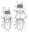
FIG. 1 is a cross-sectional view of the fluid connection system of the present invention; -
FIG. 2 is a cross-sectional view of the male connector of the present invention in partial engagement with a female connector; -
FIG. 3 is a cross-sectional view of the male connector of the present invention and a female connector; -
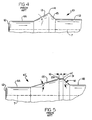
FIG. 4 is a partial perspective view of a first prior art male connector; -
FIG. 5 is a partial cross-sectional view of a second prior art male connector; -
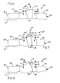
FIG. 6 is a partial cross-sectional view of a first embodiment of the male coupling of the present invention; -
FIG. 7 is a partial cross-sectional view of a second embodiment of the male coupling of the present invention; -
FIG. 8 is a partial cross-sectional view of a third embodiment of the male coupling of the present invention; -
FIG. 8A is a partial cross-sectional view of a fourth embodiment of the male coupling of the present invention; -
FIG. 9 is a partial cross-sectional view of a fifth embodiment of the male coupling of the present invention; -
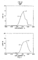
FIG. 10 is a connection force verses displacement graph of a prior art fluid connection system; -
FIG. 11 is a connection force verses displacement graph of the connection system of the present invention; and -
FIG. 12 is a connection force verses displacement graph of the connection system of the third embodiment of the present invention. - Certain terminology will be used in the following description for convenience in reference only and will not be limiting. The terms "forward" and "rearward" will refer to directions forward and rearward of the coupling as shown in the drawings. The terms "rightward" and "leftward" will refer to directions in the drawings in connection with which the terminology is used. The terms "inwardly" and "outwardly" will refer to directions toward and away from, respectively, the geometric center of the apparatus. The terms "upward" and "downward" will refer to directions as taken in the drawings in connection with which the terminology is used. All foregoing terms mentioned above include the normal derivatives and equivalents thereof.
- Now referring to
FIGS. 1 through 3 , the coupling assembly of the present invention includes amale member 20 and afemale member 30. Each of themale member 20 andfemale member 30 extends along anaxis 7 when the assembly is in the coupled position as shown inFIGS. 1 and2 . Themale member 20 extends from a leadingend 21 intended for insertion in thefemale member 30 to atrailing end 22 and has apassageway 23 extending therethrough. If desired, thetrailing end 22 may be provided withexternal threads 24 for attachment to a threaded coupling (not shown) and a series offlats 25 defining a hexagonal cross section for engagement by a wrench. - Forwardly of the hexagonal cross section defined by the
flats 25, themale member 20 has a trailing cylindricalexterior surface 26 and a leadingexterior surface 27 which are separated by a rib. The rib includes a tapered radiusedramp 28 extending rearwardly and outwardly from the leadingexterior surface 27 at an angle Y relative to theaxis 7 in the range of 10 degrees to 25 degrees and preferably at an angle of 18 degrees (seeFIG. 5 ). Theramp 28" extends to acylindrical surface 29 which is paralle to the axis and extends rearwardly from theramp 28" a distance A of at least 0.254 mm (0.010 inch) and, preferably at least 0.762 mm (0.030 inch). The final portion of the rib is ashoulder 31 which tapers rearwardly and inwardly from saidcylindrical surface 29 to meet said trailingexterior surface 26. Theshoulder 31 should taper at an angle M in the range of 35° to 55° relative to theaxis 7 and preferably at an angle of about 45° (seeFIG. 5 ). - Now referring once again to
FIG. 1 , a cross-sectional view of another component of themale member 20, a separately formedrelease sleeve 33 consisting of ametal portion 34 and a thermoplastic and/or elastomeric (TPE)portion 35 is shown. Themetal portion 34 includes a splitcylindrical wall 36 having a plurality of axial slots. As may be seen inFIG. 3 , theTPE portion 35 may be molded around the flange 42 and includes a flange portion 44 and acylindrical wall portion 45 spaced from and substantially parallel to the splitcylindrical wall 36 of themetal portion 34. During molding of theTPE portion 35 around the flange 42 of themetal portion 34, plastic and/or elastomeric material will flow into apertures formed in the flange 42 (not shown) to provide for secure attachment to themetal portion 34. TheTPE portion 35 includes asealing fin 47 extending radially inwardly from the flange portion 44. The sealingfin 47 extends inwardly sufficiently for to snugly engage the trailing cylindricalexterior surface 26 to thereby function as a dust seal to prevent dust from, or at least minimize the possibility of dust, entering the engaged coupling between therelease sleeve 33 and the trailingexterior surface 26. SeeUS 2002/019350 andUS 2002/0109351 for an alternate embodiment for therelease sleeve 33. - Referring once again to
FIGS. 1 through 3 , the secondfemale member 30 extends from a receivingend 50 to aremote end 51 which may have adjacent theretoexternal threads 52 or other suitable connection means for fastening to a separate connection (not shown). The portion of the secondfemale member 30 adjacent the receivingend 50 is provided with an exteriorcylindrical surface 52 having a size to be snugly received in thecylindrical wall 45 of therelease sleeve 33 and an interiorcylindrical surface 53 sized to receive therein the splitcylindrical wall portion 36 of themetal portion 34 ofrelease sleeve 33. An inwardly facingannular groove 54 extends outwardly from the interiorcylindrical surface 53 and is sized to receive therein a splitmetal locking ring 60. Achamfer 55 extends at an angle inwardly from theannular groove 54 toward thereceiving end 50 to meet the interiorcylindrical surface 53. The angle N (seeFIG. 5 ) between thechamfer 55 and the interiorcylindrical surface 53 is in the range of 20° to 40° and is preferably 30°. - A second interior
cylindrical surface 56 of smaller size than the firstcylindrical surface 53 is positioned toward theremote end 51 from theannular groove 54 and is joined thereto by an inwardly taperingwall portion 57. The second interiorcylindrical surface 56 is sized to receive the leadingexterior surface 27 of the firstmale member 20. The second interiorcylindrical wall surface 56 has formed therein an inwardly facingannular groove 58 in which is positioned anannular seal 59 of neoprene or other suitable sealing material and a rigidplastic ring 61 which is positioned in thegroove 58 between theannular seal 59 and the receivingend 50. Theplastic ring 61 has an aperture sized to snugly receiving the leadingexterior surface 27 of the first male member and theannular seal 59 is sized to sealingly receive and engage such leadingexterior surface 27. The presence of the rigidplastic ring 61 in a position to be engaged by the leadingend 21 of the firstmale member 20 serves to protect theannular seal 59 from cutting or other damage upon insertion of the leadingexterior surface 27 therethrough. The rigidplastic ring 61 also serves to protect theannular seal 59 from damage when used in systems having high impulse flow of fluid. - Positioned in the
annular groove 54 is a splitmetal locking ring 60 formed of a spring tempered phosphoric bronze material or, preferably, a spring tempered stainless steel. Thesplit locking ring 60 is provided with a first end and a second end which should either be in abutting relationship or have a typical gap of 0.030 inch when the firstmale member 20 is disconnected from the secondfemale member 30. Thesplit locking ring 60, when the parts are in the disconnected position, has an external diameter smaller than the diameter defined by the outermost portion of theannular groove 54 but larger than the diameter of the first interiorcylindrical surface 53. Thesplit locking ring 60 has an internal diameter substantially equal to or, preferably, slightly smaller than that of the trailingexterior surface 26 of themale member 20 to snugly engage such trailingexterior surface 26 when themale member 20 is engaged to thefemale member 30. As will be appreciated, the internal diameter of thesplit locking ring 60 is therefore, significantly smaller than the diameter of thecylindrical surface 29. Thesplit locking ring 60, by virtue of its dimensions, will be retained in theannular groove 54 when the firstmale member 20 is disconnected from the secondfemale member 21. However, by virtue of its being split, the diametrical size of the lockingring 60 may be expanded and the end portions become separated as the lockingring 60 moves over theramp 28" andcylindrical surface 29 upon insertion of the firstmale member 20 into the secondfemale member 30. - Thus, as may be seen
FIGS. 1 ,2 and 3 , upon insertion of the firstmale member 20 into the secondfemale member 30, the leadingend 21 and leadingexterior surface 27 will pass through thesplit locking ring 60 until theramp 28" reaches thesplit locking ring 60. Continued inward movement of themale member 20 will cause theramp 28" to expand the lockingring 60 thereby opening up the gap between the ends 62 and 63 by increasing amounts as the lockingring 60 moves up to the maximum diameter of theramp 28" and onto thecylindrical surface 29. As thecylindrical surface 29 moves past thesplit locking ring 60 upon continued forward movement of the firstmale member 20, thesplit locking ring 60, by virtue of the resilience of the metal will contract to a size approaching its original size and, in do so, will be positioned to prevent withdrawal of the firstmale member 20 from the secondfemale member 30 by virtue of thesplit locking ring 60 being trapped between theshoulder 31 and thechamfer 55 formed in thefemale member 30. - As will be appreciated from viewing
FIG. 1 the taperedshoulder 31 and thechamfer 55 are disposed at converging angles in the direction toward theannular groove 54 when the firstmale member 20 is engaged to thefemale member 30. This convergence results from the fact that the angle of the taperedshoulder 31 is greater than the angle of thechamfer 55 in relation to theaxis 7 as previously set forth. - When the first
male member 20 is fully engaged to the secondfemale member 30, the leadingexterior surface 27 is sealingly engaged to theannular seal 59 thereby preventing leaking of fluid. Additionally, receivingend 50 and portions of the second female member adjacent thereto are positioned in thegap 46 between thecylindrical wall portion 45 of theTPE portion 35 and the splitcylindrical wall 36 of the metal portion. The exteriorcylindrical surface 52 is snugly in contact with the interior of thecylindrical wall portion 45 thereby preventing, along with the sealingfin 47, dust or other contaminants from the entering the area around the splitmetal locking ring 60 when the members are in the engaged position ofFIG. 1 . - Again, as can be seen from
FIG. 1 , when the firstmale member 20 is in the fully coupled or engaged position with the secondfemale member 30, there is a space between the receivingend 50 and the interior of the flange portion 44 which is, in effect, the end of thegap 46. Additionally, the leading end 38 of the release sleeve splitcylindrical wall 36 is barely touching or, preferably, slightly spaced from the splitmetal locking ring 60. When it is desired to disconnect the firstmale member 20 from the secondfemale member 30, it is simply necessary to move therelease sleeve 33 toward the leadingend 21 thereby causing the leading end 38 of the split cylindrical wall to urge the splitmetal locking ring 60 axially toward the rib and, in so doing, to be urged outwardly by the taperedshoulder 31 against which the splitmetal locking ring 60 is being urged by the release sleeve. - As will be appreciated, when the split
metal locking ring 60 has been urged to a position in alignment with thecylindrical surface 29 of the rib, the firstmale member 20 will be released from the secondfemale member 30 and may be removed therefrom. Inasmuch as therelease sleeve 33 has a splitcylindrical wall 36 with slots 37, the segments of the splitcylindrical wall 36 between the slots 37 can be deflected outwardly by the taperedshoulder 31 thereby ensuring that therelease sleeve 33 can be moved far enough toward the leadingend 21 to ensure that it forces the splitmetal locking ring 60 out of engagement with the taperedshoulder 31 and into theannular groove 54 as it engages thecylindrical surface 29 thereby permitting release of themale member 20 from the female member. In being moved to the extreme release position toward the leadingend 21, the portion of the release sleeve splitcylindrical wall 36 adjacent the leading end 38 may be deflected outwardly by the movement of the leading end 38 against the taperedshoulder 31. - In the manufacture of couplings designed to meet standards of the Society of Automotive Engineers (SAE) it is customary to manufacture such couplings from G12000 series steel as set forth in the Unified Numbering System for SAE and the American Iron and Steel Institute (AISI) and are designed to be used with hydraulic hoses meeting standards established by SAE. For example, the prior art device shown in
FIGS. 7 through 9 ofU.S. Pat. No. 5,226,682 is suitable for operating with hydraulic hose meeting SAE Standard J517-Series 100R2. Couplings for use in automotive applications in Europe are also manufactured from G12000 series steel but must meet standards issued by Deutsches Institut für Normung (DIN), Berlin, Germany. DIN Standard 20022 Part 2 includes standards for Type 2ST hoses which are more stringent than those of the corresponding SAE J517-Series 100R2 Pressure Standard. - Prior art couplings of the type utilizing a rib and a split metal lock ring which have been tested withstand pressures of four times the specified Operating Pressure for the SAE 100R2 Standards but not for the DIN Type 2ST Standards. In contrast, the coupling assembly of the present invention is capable of withstanding pressures of four times the specified Operating Pressures for both the SAE 100R2 Standards and the DIN Type 2ST Standards.
- Now referring to
FIG. 4 , a partial cross-sectional view of a priorart male member 10 is shown. This embodiment is disclosed inU.S. Pat. Nos. 5,226,682 and5,553,895 and includes aramp 13 which uniformly increases at angle X in axial distance fromcenterline 17 along the leading exterior surface 11A to reach an apex 14. Ashoulder 15 then joins the apex 14 to the trailing exterior surface 11 B. The leadingend 12 is inserted into a female coupling. -
FIG. 5 is a partial cross-sectional view of a priorart male member 20 as disclosed inU.S. Pat. No. 5,553,895 inFIG. 2 of that patent. Forwardly, of the hexagonal cross section defined by theflats 25, the male member 10' has a trailing cylindrical exterior surface 11 B and a leading exterior surface 11A which are separated by a rib. The rib or ridge includes a tapered ramp 13' extending rearwardly and outwardly from the leading exterior surface 11A at an angle X' relative to theaxis 7 in the range of 10° to 25° and preferably at an angle of 18°. The ramp 13' extends to a cylindrical surface or flat 29 which is parallel to the axis and extends rearwardly from the ramp 13' a distance A of at least 0.254 mm (0.010 inch) and, preferably at least 0.762 mm (0.030 inch). The final portion of the rib is ashoulder 31 which tapers rearwardly and inwardly from saidcylindrical surface 29 to meet said trailing exterior surface 11 B. Theshoulder 31 should taper at an angle M in the range of 35° to 55° relative to theaxis 7 and preferably at an angle of about 45°. - Now referring to
FIG. 6 , a first embodiment of the elevational view of the male member 20' of the present invention is shown. Refer toFIGS. 4 and 5 of this application and toFIGS. 1 and2 ofU.S. Pat. No. 5,553,895 for examples of prior art male ramp configurations. The male member 20' extends from a leadingend 21 to a trailingend 23 as shown inFIG. 1 . The male member 20' has a trailing cylindricalexterior surface 26 and a leading cylindricalexterior surface 27 which are separated by a ridge or rib 15'. The leadingend 21 is intended to be inserted into thefemale member 30. The rib 15' is comprised of a ramp 28' beginning atbreak point 22 and extending rearwardly (to the right) and outwardly from the leadingexterior surface 27 at a curved angle. Shown inFIG. 6 for reference purposes is angle Y relative to theaxis 7 which can vary along with the angle of the ramp 28' in the range of 10° to approximately 25°, preferably at an angle Y of 18°. According to the present invention, the profile of the ramp 28' has been changed from a uniform, straight, cone-like surface to an outwardly curved surface. A section of a circle having radius R' describes the approximate profile of the ramp 28' in the first embodiment of the present invention extending from the leadingexterior surface 27 to the apex 14 of the ramp 28'. It is contemplated that the curved outer surface of the ramp 28' need not be a section of a circle with radius R' but could be varied in curvature to yield the desired force verses displacement curve for thesplit locking ring 60 or other more complicated shapes could be utilized. The rib 15' of the first embodiment of the present invention provides a more desired force/displacement curve for the splitmetal locking ring 60 as it traverses the rib 28' upon insertion of the male member 20' into thefemale member 30. - Now referring to
FIG. 7 , an elevational view of a second embodiment of themale member 20" of the present invention is shown. Themale member 20" extends from a leading end 21' to a trailingend 23 as shown inFIG. 7 . Themale member 20" has a trailing cylindricalexterior surface 26 and a leading cylindricalexterior surface 27 which are separated by a ridge orrib 15". The leadingend 21 is intended to be inserted into thefemale member 30. Therib 15" is comprised of aramp 28" extending rearwardly (to the right) and outwardly from the leadingexterior surface 27. A flat 29 of width A' extends from the end of theramp 28" atpoint 16 to the apex 14' ofshoulder 31. The surface of the flat 29 extends approximately parallel to theaxis 7 of themale member 20". Theshoulder 31 is at an angle of M with theaxis 7 of themale member 20" while the dottedline 19 frombreak point 22 to point 16 is at an angle Y of approximately in the range of 10° through 25° with a preferred value of 18°. Theactual surface ramp 28" is radiused to extend outwardly fromdotted line 19 and is shown shaped as a section of a circle with radius R" and intersecting atbreak point 22 andpoint 16. Radius R" is selected so that the maximum height of theramp 28" does not exceed the height of the flat 29 above theaxis 7 of themale member 20". - Now referring to
FIG. 8 of the drawings, a cross-sectional view of a third embodiment of the male member 20'" of the present invention is shown. The male member 20'" extends from a leadingend 21 to a trailingend 23 as shown inFIG. 8 . Themale member 20"' has a trailing cylindricalexterior surface 26 and a leading cylindricalexterior surface 27 which are separated by arib 15"'. The leadingend 21 is intended to be inserted into thefemale member 30. The rib 15'" is comprised of a ramp 28'" extending rearwardly (to the right) topoint 17 and outwardly from the leadingexterior surface 27. Theshoulder 31 is at an angle of M with theaxis 7 of themale member 20"'. Theramp 28"' extends at a direct straight line frombreak point 22 to point 17 at an angle Y from theaxis 7 although theramp 28"' could extend in other shapes as well such as a curved shape. A radiused section having a radius R'" extends frompoint 17 to apex 14' and defines aradiused section 9. Radius R"' is chosen such that the maximum height of the ramp 28'" does not exceed the maximum height of the flat 29 from theaxis 7 blends theramp 28"' to the apex 14' and yields the desired insertion force verses displacement curve. - Now referring to
FIG. 8A of the drawings, a cross-sectional view of a fourth embodiment of themale member 20"" of the present invention is shown. Themale member 20"" is similar to the male member 20'" shown inFIG. 8 except a flat 29' (flat) of width A" of approximately 0.254 mm (0.010 inch) joins the radiused section 19' extending frompoint 17 to point 16' to the apex 14'. The radiused section 19' as defined extending frompoint 17 to point 16' has a radius of R"" and blends in to join theramp 28"' to the cylindrical surface 29'. - The
male member 20"' extends from a leadingend 21 to a trailingend 23 as shown inFIG. 8A . The male member 20'" has a trailing cylindricalexterior surface 26 and a leading cylindricalexterior surface 27 which are separated by a ridge orrib 15"". The leadingend 21 is intended to be inserted into thefemale member 30. Therib 15"" is comprised of a ramp 28'" beginning atbreak point 22 and extending rearwardly (to the right) and extending in outwardly from the leadingexterior surface 27. Theramp 28"' is connected to the apex 14' via first a radiused section 19' extending frompoint 17 to point 16' and then a cylindrical section or flat 29'. - The ramp 28'" extends at a direct straight line from
break point 22 to point 17 at an angle Y from theaxis 7. The ramp 28'" could also extend in other shapes such as a radiused cross-sectional shape or other curved or multiple straight line shapes. The radius R"" is chosen to provide a blend between the ramp 28'" and the flat 29'. The combination of theramp 28"', the radiused section 9' and the flat 29' combine to determine the characteristic of the insertion force as the male member 20'" is inserted into thefemale member 30. - Now referring to
FIG. 9 of the drawings, a partial cross-sectional view of a fourth embodiment of themale member 20""' of the present invention is shown. Themale member 20""' extends from a leadingend 21 to a trailingend 23 as shown inFIG. 9 . Themale member 20""' has a trailing cylindricalexterior surface 26 and a leading cylindricalexterior surface 27 which are separated by arib 15""'. The leadingend 21 is intended to be inserted into thefemale member 30. Therib 15""' is comprised of aramp 28"" extending rearwardly (to the right) and outwardly from the leadingexterior surface 27 at an angle of Z as opposed to angle Y as shown inFIG. 8 . Theramp 28"" is shown as a relatively straight line extending from thebreak point 22 to the point 17' but could be slightly curved outwardly from theaxis 7. From point 17' to apex 14', a outwardly extending curve is formed with a radius R""' having a maximum distance from theaxis 7 atpoint 40. The radial distance ofpoint 40 from theaxis 7 is greater than the radial distance of the apex 14' from theaxis 7. This increased distance results in a favorable load verses displacement curve as shown inFIG. 12 for this fourth alternate embodiment. The lockingring 60 becomes trapped between theshoulder 31 and thechamfer 55 as previously described. - Now referring to
FIG. 10 , a graph of insertion force in pounds force verses displacement in inches for a typical prior art connector system such as that disclosed inU.S. Pat. No. 5,553,895 is shown. Themale member 20 requires a minimum force (Ibf) to engage thefemale member 30 and complete the connection. This can be graphically represented in the graph shown inFIG. 10 for the prior art coupling where the curve C reaches a peak level of force of 62.3 N (14 lbf) at point P at approximately 3.81 mm (0.15 inch) from the start of theramp 28. -
FIG. 11 shows a graph of projected data for the insertion force in pounds force verses displacement in inches for the first three embodiments of the coupling of the present invention. Although the three embodiments as shown inFIGS. 6 through 8 will exhibit a slightly different characteristic force verses displacement curve,FIG. 11 is a typical result as themale member 20 is inserted into thefemale member 30. Curve C' increases in a manner similar to the curve C initially while the peak force P' of the coupling of the present invention is significantly lower at 53.4 N (12 lbf). This results in a connection that is more easily made by an assembly person. - Now referring to
FIG. 12 of the drawings, a graphical representation of the load required to connect themale member 20"" into thefemale member 30 is shown.FIG. 12 is projected data for the shape of themale member 20"" shown inFIG. 9 . The load verses displacement graph shown inFIG. 11 applies generally to the male members shown inFIGS. 6 through 8 . - Referring both to
FIGS. 9 and12, FIG. 12 shows that the load curve C" increases at a fairly rapid rate as the lockingring 60 engages and travels up theramp 28"" to point 17 and reaches a peak value P" of approximately 66.7 N (15 lbf) an then rapidly decreases as the lockingring 60 reaches point 40 on themale member 20"". After thelocking ring 60 passes to the right ofpoint 40, due to the forces generated when the lockingring 60 is increased in diameter over its free state, it actually helps pull themale member 20"" into thefemale member 30 thereby assisting in effectuating the final connection where the lockingring 60 engages theshoulder 31 and thechamfer 55 as the lockingring 60 returns to its original diameter.
Claims (5)
- A coupling assembly having an axis (7) comprising:(a) a male member (20) extending from a leading end (21) to a trailing end (22), a first cylindrical exterior surface (27) extending from said leading end (21), a second cylindrical exterior surface (26) spaced from said first cylindrical exterior surface (27) and a rib (15) between said first cylindrical exterior surface (27) and said second cylindrical exterior surface (26), said rib (15) including (i) a curved ramp (28) extending axially away from said leading end (21) and outwardly from said first exterior cylindrical surface (27) at a radius, and (ii) a shoulder (31) tapering inwardly and axially away from said first cylindrical exterior surface portion (27); and(b) a female member (30) including a receiving end (50) with a cavity sized to receive said male member (20), said cavity including a first inwardly facing cylindrical surface (53) adjacent said receiving end (50) sized to receive said rib (15), an inwardly facing annular groove (54) including spaced apart first and second surfaces extending outwardly from said first inwardly facing cylindrical surface (53), said second groove surface being positioned between said receiving end (50) and said first groove surface and including a chamfer (55) tapering toward said axis (7) and said receiving end (50) of an angle relative to said axis (7) which is less than the angle (M) between said shoulder (31) and said axis (7), and a second inwardly facing surface (56) sized to receive said male member (20) leading end (21) and first cylindrical exterior surface (27); and(c) a split locking ring (60) positioned in said female member (30) inwardly facing annular groove (54) and sized for movement in said annular groove (54), said split locking ring (60) having a first end and a second end aligned for abutting relationship and having a gap, said split locking ring (60) having an interior diameter sized to receive said male member (20) first cylindrical exterior surface portion (27) and to be engaged and expanded to a larger radial size by said ramp (28) upon movement of said male member (20) further into said cavity, said split locking ring (60) retracting in diametrical size resiliently to become trapped between said shoulder (31) and said chamfer (55) upon the movement of said male member (20) to a position in which said tapered shoulder (31) is axially aligned with said split locking ring (60).
- A coupling assembly according to claim 1, wherein
said rib (15", 15"") further including a cylindrical exterior surface portion (29, 29') joined to said ramp (28", 28"'), substantially parallel to said axis (7), having a minimum axial distance of 0.010 inch, and joined to said shoulder (31). - A coupling assembly according to claim 2, wherein
said ramp (28"') extending axially away from said leading end and (21) outwardly at a steadily increasing distance from said first exterior cylindrical surface (27) joined to a radiused portion (9') curved to join said cylindrical exterior surface portion (29'). - A coupling assembly according to claim 1, wherein
said ramp (28"") including a radiused portion extending in a curved manner from said first exterior cylindrical surface (27) and joined to said shoulder (31'); where the maximum distance of said radiused portion from said first cylindrical exterior surface (27) exceeds the maximum distance of said shoulder (31') from said first cylindrical exterior surface (27). - A coupling assembly according to claim 1, wherein
said ramp (28) including a radiused portion extending in a curved manner from said first exterior cylindrical surface (27) and joined to a cylindrical exterior surface portion (29) substantially parallel to said axis (7), said cylindrical exterior surface portion (29) joined to said shoulder (31), where the maximum distance of said radiused portion from said first cylindrical exterior surface (27) exceeds the maximum distance of said shoulder (31) from said first cylindrical exterior surface (27).
Applications Claiming Priority (3)
| Application Number | Priority Date | Filing Date | Title |
|---|---|---|---|
| US228793 | 2002-08-27 | ||
| US10/228,793 US6769720B2 (en) | 2002-08-27 | 2002-08-27 | Coupling assembly with profiled ramp |
| PCT/IB2003/003313 WO2004020892A1 (en) | 2002-08-27 | 2003-08-14 | Coupling assembly with profiled ramp |
Publications (2)
| Publication Number | Publication Date |
|---|---|
| EP1579142A1 EP1579142A1 (en) | 2005-09-28 |
| EP1579142B1 true EP1579142B1 (en) | 2013-12-18 |
Family
ID=31976110
Family Applications (1)
| Application Number | Title | Priority Date | Filing Date |
|---|---|---|---|
| EP03791077.5A Expired - Lifetime EP1579142B1 (en) | 2002-08-27 | 2003-08-14 | Coupling assembly with profiled ramp |
Country Status (6)
| Country | Link |
|---|---|
| US (1) | US6769720B2 (en) |
| EP (1) | EP1579142B1 (en) |
| JP (1) | JP4560781B2 (en) |
| CN (1) | CN100572884C (en) |
| AU (1) | AU2003251096A1 (en) |
| WO (1) | WO2004020892A1 (en) |
Families Citing this family (21)
| Publication number | Priority date | Publication date | Assignee | Title |
|---|---|---|---|---|
| JP4252785B2 (en) * | 2002-10-01 | 2009-04-08 | 株式会社パイオラックス | Piping connector and manufacturing method thereof |
| JP4291989B2 (en) * | 2002-10-01 | 2009-07-08 | 株式会社パイオラックス | Piping connector |
| US7029035B2 (en) * | 2003-09-11 | 2006-04-18 | International Engine Intellectual Property Company, Llc | Release collar for coupling assembly |
| MXPA06008556A (en) * | 2004-01-27 | 2006-08-28 | Eaton Corp | Coupling assembly with latching sleeve. |
| US7488006B2 (en) * | 2004-02-02 | 2009-02-10 | Eaton Corporation | Coupling assembly |
| US7600790B2 (en) * | 2004-10-20 | 2009-10-13 | Eaton Corporation | Coupling assembly with connection indicator |
| US20060185124A1 (en) | 2005-02-18 | 2006-08-24 | Kozlowski Keith A | Joint assembly with centering flange |
| US20060273577A1 (en) * | 2005-05-17 | 2006-12-07 | Stewart Michael B | Coupling assembly |
| US7419012B2 (en) * | 2006-10-26 | 2008-09-02 | Varco I/P, Inc. | Wellbore top drive systems |
| US20100055652A1 (en) * | 2008-08-29 | 2010-03-04 | Karen Miller-Kovach | Processes and systems based on dietary fiber as energy |
| US9217527B2 (en) | 2010-07-06 | 2015-12-22 | Caterpillar Inc. | No-skive hydraulic hose coupling with improved hose retention and sealing |
| US9958100B2 (en) | 2010-10-15 | 2018-05-01 | Swagelok Company | Push to connect conduit fitting with ferrule |
| DE102012102191A1 (en) | 2012-03-15 | 2013-09-19 | Voss Automotive Gmbh | "Plug-in connection system, in particular for fluidic lines, fittings or aggregates" |
| EP3060839B1 (en) | 2013-10-24 | 2020-03-18 | Swagelok Company | Single action push to connect conduit fitting |
| EP3286476B1 (en) | 2015-04-23 | 2019-10-02 | Swagelok Company | Push to connect fitting assembly for a conduit |
| US10458582B2 (en) | 2015-04-23 | 2019-10-29 | Swagelok Company | Single action push to connect conduit fitting with colleting |
| GB2547731A (en) * | 2016-02-25 | 2017-08-30 | Eaton Ind Ip Gmbh & Co Kg | Connection assembly |
| US10781958B2 (en) * | 2017-10-31 | 2020-09-22 | Oetiker Ny, Inc. | Low peak insertion tube end form |
| CN108771496A (en) * | 2018-09-19 | 2018-11-09 | 杨立阳 | A kind of coupler |
| CN109702435B (en) * | 2018-12-14 | 2020-05-29 | 中联重科股份有限公司 | Flange assembly and machining method thereof |
| US11781688B2 (en) | 2019-04-01 | 2023-10-10 | Swagelok Company | Push to connect conduit fitting assemblies and arrangements |
Family Cites Families (34)
| Publication number | Priority date | Publication date | Assignee | Title |
|---|---|---|---|---|
| US1771949A (en) | 1928-08-30 | 1930-07-29 | Charles Cory & Son Inc | Hose fitting |
| US2092116A (en) | 1935-11-07 | 1937-09-07 | Fred E Hansen | Hose coupling |
| US2225610A (en) | 1938-01-03 | 1940-12-24 | Bendix Aviat Corp | Hose coupling |
| US2299643A (en) | 1940-07-03 | 1942-10-20 | Frederick K Moody | Valved connector |
| US2479960A (en) | 1946-01-10 | 1949-08-23 | Alden E Osborn | Pipe joint |
| US2805089A (en) | 1954-12-30 | 1957-09-03 | Hansen Mfg Co | Pipe coupling with wedged spring ring detent means |
| US2848255A (en) | 1955-03-24 | 1958-08-19 | Mcneil Machine & Eng Co | Lubricant fitting coupler with wedged lock ring |
| US3120968A (en) | 1960-04-21 | 1964-02-11 | John H Calvin | Quick disconnect coupling with ring detent |
| US3177018A (en) | 1963-01-02 | 1965-04-06 | Aeroquip Corp | Snap ring coupling |
| US3398977A (en) | 1965-02-13 | 1968-08-27 | Yoneda Rikizo | Pipe coupling |
| US3773360A (en) | 1972-09-01 | 1973-11-20 | W Timbers | Quick disconnect coupling |
| US3887222A (en) | 1974-07-25 | 1975-06-03 | Hansen Mfg | Coupling with push-pull release |
| US4055359A (en) | 1975-11-17 | 1977-10-25 | Ford Motor Company | Quick-connect tubular couplings |
| US4111464A (en) | 1976-01-19 | 1978-09-05 | Sekisui Kagaku Kogyo Kabushiki Kaisha | Pipe joint locking ring and groove arrangement |
| US4105226A (en) | 1976-06-01 | 1978-08-08 | Celanese Corporation | Snap-in fittings and coupling ring therefor |
| FR2461876A1 (en) * | 1979-07-23 | 1981-02-06 | Staubli Sa Ets | IMPROVEMENTS TO QUICK CONNECTION DEVICES FOR JOINING PIPES |
| US4240654A (en) | 1979-09-28 | 1980-12-23 | International Harvester Company | Hose end coupling unit |
| US4401326A (en) | 1981-12-16 | 1983-08-30 | Ford Motor Company | Quick-connect tubular coupling |
| FR2554543B1 (en) | 1983-11-09 | 1986-07-25 | Gromelle Raymond | FITTING FOR QUICK MOUNTING OF A PIPING TUBE IN A TAP HOLE |
| US4750765A (en) | 1987-07-27 | 1988-06-14 | Stratoflex, Inc. | Quick-connect coupling |
| US5042848A (en) | 1987-11-16 | 1991-08-27 | Fujipura Seiko Co. | Swivelable connector for tubular conduits |
| US4906031A (en) | 1988-07-21 | 1990-03-06 | Stratoflex, Inc. | Quick connect coupling with garter spring |
| US4872710A (en) | 1988-10-07 | 1989-10-10 | Stratoflex, Inc. | Releasable quick connect fitting |
| US5005877A (en) | 1988-12-16 | 1991-04-09 | Parker Hannifin Corporation | Quick connect/disconnect fluid coupling |
| CA2004975A1 (en) | 1988-12-16 | 1990-06-16 | Lawrence F. Hayman | Quick connect/disconnect fluid coupling |
| US5022687A (en) | 1989-09-18 | 1991-06-11 | Yokohama Aeroquip Corporation | Pipe coupling |
| US5076541A (en) | 1989-12-15 | 1991-12-31 | A. Y. Mcdonald Manufacturing Company | Tamperproof rotary valve |
| US5301408A (en) | 1992-03-31 | 1994-04-12 | R & B, Inc. | Garter spring coupling release tool |
| US5226682A (en) | 1992-07-21 | 1993-07-13 | Aeroquip Corporation | Coupling assembly |
| EP0615089A1 (en) | 1993-03-06 | 1994-09-14 | DEUTSCHE TECALEMIT GmbH | Separable plug-in connection for high pressure conduits |
| US5553895A (en) * | 1995-05-03 | 1996-09-10 | Aeroquip Corporation | Coupling assembly |
| US5570910A (en) | 1995-08-18 | 1996-11-05 | Aeroquip Corporation | Coupling assembly |
| US6588805B2 (en) | 2000-10-03 | 2003-07-08 | Eaton Aeroquip, Inc. | Coupling adapter and assembly |
| US6494494B2 (en) | 2001-02-15 | 2002-12-17 | Eaton Aeroquip, Inc. | Coupling assembly |
-
2002
- 2002-08-27 US US10/228,793 patent/US6769720B2/en not_active Expired - Lifetime
-
2003
- 2003-08-14 CN CNB038201283A patent/CN100572884C/en not_active Expired - Lifetime
- 2003-08-14 WO PCT/IB2003/003313 patent/WO2004020892A1/en active Application Filing
- 2003-08-14 JP JP2004532367A patent/JP4560781B2/en not_active Expired - Lifetime
- 2003-08-14 AU AU2003251096A patent/AU2003251096A1/en not_active Abandoned
- 2003-08-14 EP EP03791077.5A patent/EP1579142B1/en not_active Expired - Lifetime
Also Published As
| Publication number | Publication date |
|---|---|
| WO2004020892A1 (en) | 2004-03-11 |
| JP2006516318A (en) | 2006-06-29 |
| CN100572884C (en) | 2009-12-23 |
| EP1579142A1 (en) | 2005-09-28 |
| WO2004020892A8 (en) | 2004-05-27 |
| JP4560781B2 (en) | 2010-10-13 |
| AU2003251096A1 (en) | 2004-03-19 |
| CN1784568A (en) | 2006-06-07 |
| US6769720B2 (en) | 2004-08-03 |
| US20040041394A1 (en) | 2004-03-04 |
Similar Documents
| Publication | Publication Date | Title |
|---|---|---|
| EP1579142B1 (en) | Coupling assembly with profiled ramp | |
| US5553895A (en) | Coupling assembly | |
| AU709285B2 (en) | Fluid couplings | |
| US5570910A (en) | Coupling assembly | |
| US4991882A (en) | Fluid-tight connector | |
| WO1995026479A1 (en) | Deep drawn quick connect coupling | |
| AU2005209763B2 (en) | Coupling assembly | |
| US20040070197A1 (en) | Coupling assembly | |
| CA2554681C (en) | Coupling assembly with latching sleeve | |
| US20030057699A1 (en) | Coupling assembly with rotation lock | |
| EP1650485A2 (en) | Coupling assembly with connection indicator | |
| MXPA06008775A (en) | Coupling assembly |
Legal Events
| Date | Code | Title | Description |
|---|---|---|---|
| PUAI | Public reference made under article 153(3) epc to a published international application that has entered the european phase |
Free format text: ORIGINAL CODE: 0009012 |
|
| 17P | Request for examination filed |
Effective date: 20050708 |
|
| AK | Designated contracting states |
Kind code of ref document: A1 Designated state(s): AT BE BG CH CY CZ DE DK EE ES FI FR GB GR HU IE IT LI LU MC NL PT RO SE SI SK TR |
|
| AX | Request for extension of the european patent |
Extension state: AL LT LV MK |
|
| DAX | Request for extension of the european patent (deleted) | ||
| 17Q | First examination report despatched |
Effective date: 20090212 |
|
| GRAP | Despatch of communication of intention to grant a patent |
Free format text: ORIGINAL CODE: EPIDOSNIGR1 |
|
| GRAS | Grant fee paid |
Free format text: ORIGINAL CODE: EPIDOSNIGR3 |
|
| GRAA | (expected) grant |
Free format text: ORIGINAL CODE: 0009210 |
|
| AK | Designated contracting states |
Kind code of ref document: B1 Designated state(s): AT BE BG CH CY CZ DE DK EE ES FI FR GB GR HU IE IT LI LU MC NL PT RO SE SI SK TR |
|
| REG | Reference to a national code |
Ref country code: GB Ref legal event code: FG4D |
|
| REG | Reference to a national code |
Ref country code: CH Ref legal event code: EP |
|
| REG | Reference to a national code |
Ref country code: AT Ref legal event code: REF Ref document number: 645799 Country of ref document: AT Kind code of ref document: T Effective date: 20140115 |
|
| REG | Reference to a national code |
Ref country code: IE Ref legal event code: FG4D |
|
| REG | Reference to a national code |
Ref country code: DE Ref legal event code: R096 Ref document number: 60345471 Country of ref document: DE Effective date: 20140213 |
|
| REG | Reference to a national code |
Ref country code: NL Ref legal event code: VDEP Effective date: 20131218 |
|
| PG25 | Lapsed in a contracting state [announced via postgrant information from national office to epo] |
Ref country code: FI Free format text: LAPSE BECAUSE OF FAILURE TO SUBMIT A TRANSLATION OF THE DESCRIPTION OR TO PAY THE FEE WITHIN THE PRESCRIBED TIME-LIMIT Effective date: 20131218 Ref country code: SE Free format text: LAPSE BECAUSE OF FAILURE TO SUBMIT A TRANSLATION OF THE DESCRIPTION OR TO PAY THE FEE WITHIN THE PRESCRIBED TIME-LIMIT Effective date: 20131218 |
|
| REG | Reference to a national code |
Ref country code: AT Ref legal event code: MK05 Ref document number: 645799 Country of ref document: AT Kind code of ref document: T Effective date: 20131218 |
|
| PG25 | Lapsed in a contracting state [announced via postgrant information from national office to epo] |
Ref country code: EE Free format text: LAPSE BECAUSE OF FAILURE TO SUBMIT A TRANSLATION OF THE DESCRIPTION OR TO PAY THE FEE WITHIN THE PRESCRIBED TIME-LIMIT Effective date: 20131218 Ref country code: BE Free format text: LAPSE BECAUSE OF FAILURE TO SUBMIT A TRANSLATION OF THE DESCRIPTION OR TO PAY THE FEE WITHIN THE PRESCRIBED TIME-LIMIT Effective date: 20131218 |
|
| PG25 | Lapsed in a contracting state [announced via postgrant information from national office to epo] |
Ref country code: RO Free format text: LAPSE BECAUSE OF FAILURE TO SUBMIT A TRANSLATION OF THE DESCRIPTION OR TO PAY THE FEE WITHIN THE PRESCRIBED TIME-LIMIT Effective date: 20131218 Ref country code: CY Free format text: LAPSE BECAUSE OF FAILURE TO SUBMIT A TRANSLATION OF THE DESCRIPTION OR TO PAY THE FEE WITHIN THE PRESCRIBED TIME-LIMIT Effective date: 20131218 Ref country code: PT Free format text: LAPSE BECAUSE OF FAILURE TO SUBMIT A TRANSLATION OF THE DESCRIPTION OR TO PAY THE FEE WITHIN THE PRESCRIBED TIME-LIMIT Effective date: 20140418 Ref country code: CZ Free format text: LAPSE BECAUSE OF FAILURE TO SUBMIT A TRANSLATION OF THE DESCRIPTION OR TO PAY THE FEE WITHIN THE PRESCRIBED TIME-LIMIT Effective date: 20131218 Ref country code: NL Free format text: LAPSE BECAUSE OF FAILURE TO SUBMIT A TRANSLATION OF THE DESCRIPTION OR TO PAY THE FEE WITHIN THE PRESCRIBED TIME-LIMIT Effective date: 20131218 Ref country code: AT Free format text: LAPSE BECAUSE OF FAILURE TO SUBMIT A TRANSLATION OF THE DESCRIPTION OR TO PAY THE FEE WITHIN THE PRESCRIBED TIME-LIMIT Effective date: 20131218 Ref country code: ES Free format text: LAPSE BECAUSE OF FAILURE TO SUBMIT A TRANSLATION OF THE DESCRIPTION OR TO PAY THE FEE WITHIN THE PRESCRIBED TIME-LIMIT Effective date: 20131218 Ref country code: SK Free format text: LAPSE BECAUSE OF FAILURE TO SUBMIT A TRANSLATION OF THE DESCRIPTION OR TO PAY THE FEE WITHIN THE PRESCRIBED TIME-LIMIT Effective date: 20131218 |
|
| REG | Reference to a national code |
Ref country code: DE Ref legal event code: R097 Ref document number: 60345471 Country of ref document: DE |
|
| PLBE | No opposition filed within time limit |
Free format text: ORIGINAL CODE: 0009261 |
|
| STAA | Information on the status of an ep patent application or granted ep patent |
Free format text: STATUS: NO OPPOSITION FILED WITHIN TIME LIMIT |
|
| PG25 | Lapsed in a contracting state [announced via postgrant information from national office to epo] |
Ref country code: DK Free format text: LAPSE BECAUSE OF FAILURE TO SUBMIT A TRANSLATION OF THE DESCRIPTION OR TO PAY THE FEE WITHIN THE PRESCRIBED TIME-LIMIT Effective date: 20131218 |
|
| 26N | No opposition filed |
Effective date: 20140919 |
|
| REG | Reference to a national code |
Ref country code: DE Ref legal event code: R097 Ref document number: 60345471 Country of ref document: DE Effective date: 20140919 |
|
| PG25 | Lapsed in a contracting state [announced via postgrant information from national office to epo] |
Ref country code: LU Free format text: LAPSE BECAUSE OF FAILURE TO SUBMIT A TRANSLATION OF THE DESCRIPTION OR TO PAY THE FEE WITHIN THE PRESCRIBED TIME-LIMIT Effective date: 20140814 Ref country code: MC Free format text: LAPSE BECAUSE OF FAILURE TO SUBMIT A TRANSLATION OF THE DESCRIPTION OR TO PAY THE FEE WITHIN THE PRESCRIBED TIME-LIMIT Effective date: 20131218 |
|
| REG | Reference to a national code |
Ref country code: CH Ref legal event code: PL |
|
| PG25 | Lapsed in a contracting state [announced via postgrant information from national office to epo] |
Ref country code: CH Free format text: LAPSE BECAUSE OF NON-PAYMENT OF DUE FEES Effective date: 20140831 Ref country code: LI Free format text: LAPSE BECAUSE OF NON-PAYMENT OF DUE FEES Effective date: 20140831 |
|
| REG | Reference to a national code |
Ref country code: IE Ref legal event code: MM4A |
|
| PG25 | Lapsed in a contracting state [announced via postgrant information from national office to epo] |
Ref country code: SI Free format text: LAPSE BECAUSE OF FAILURE TO SUBMIT A TRANSLATION OF THE DESCRIPTION OR TO PAY THE FEE WITHIN THE PRESCRIBED TIME-LIMIT Effective date: 20131218 |
|
| PG25 | Lapsed in a contracting state [announced via postgrant information from national office to epo] |
Ref country code: IE Free format text: LAPSE BECAUSE OF NON-PAYMENT OF DUE FEES Effective date: 20140814 |
|
| PG25 | Lapsed in a contracting state [announced via postgrant information from national office to epo] |
Ref country code: BG Free format text: LAPSE BECAUSE OF FAILURE TO SUBMIT A TRANSLATION OF THE DESCRIPTION OR TO PAY THE FEE WITHIN THE PRESCRIBED TIME-LIMIT Effective date: 20131218 |
|
| PG25 | Lapsed in a contracting state [announced via postgrant information from national office to epo] |
Ref country code: GR Free format text: LAPSE BECAUSE OF FAILURE TO SUBMIT A TRANSLATION OF THE DESCRIPTION OR TO PAY THE FEE WITHIN THE PRESCRIBED TIME-LIMIT Effective date: 20140319 |
|
| REG | Reference to a national code |
Ref country code: FR Ref legal event code: PLFP Year of fee payment: 14 |
|
| PG25 | Lapsed in a contracting state [announced via postgrant information from national office to epo] |
Ref country code: HU Free format text: LAPSE BECAUSE OF FAILURE TO SUBMIT A TRANSLATION OF THE DESCRIPTION OR TO PAY THE FEE WITHIN THE PRESCRIBED TIME-LIMIT; INVALID AB INITIO Effective date: 20030814 Ref country code: TR Free format text: LAPSE BECAUSE OF FAILURE TO SUBMIT A TRANSLATION OF THE DESCRIPTION OR TO PAY THE FEE WITHIN THE PRESCRIBED TIME-LIMIT Effective date: 20131218 |
|
| REG | Reference to a national code |
Ref country code: FR Ref legal event code: PLFP Year of fee payment: 15 |
|
| REG | Reference to a national code |
Ref country code: FR Ref legal event code: PLFP Year of fee payment: 16 |
|
| REG | Reference to a national code |
Ref country code: DE Ref legal event code: R119 Ref document number: 60345471 Country of ref document: DE |
|
| PG25 | Lapsed in a contracting state [announced via postgrant information from national office to epo] |
Ref country code: DE Free format text: LAPSE BECAUSE OF NON-PAYMENT OF DUE FEES Effective date: 20200303 |
|
| PGFP | Annual fee paid to national office [announced via postgrant information from national office to epo] |
Ref country code: IT Payment date: 20220712 Year of fee payment: 20 Ref country code: GB Payment date: 20220707 Year of fee payment: 20 |
|
| PGFP | Annual fee paid to national office [announced via postgrant information from national office to epo] |
Ref country code: FR Payment date: 20220721 Year of fee payment: 20 |
|
| P01 | Opt-out of the competence of the unified patent court (upc) registered |
Effective date: 20230617 |
|
| REG | Reference to a national code |
Ref country code: GB Ref legal event code: PE20 Expiry date: 20230813 |
|
| PG25 | Lapsed in a contracting state [announced via postgrant information from national office to epo] |
Ref country code: GB Free format text: LAPSE BECAUSE OF EXPIRATION OF PROTECTION Effective date: 20230813 |