EP1576867B1 - Process-oriented board with modular spc integration and expansion - Google Patents
Process-oriented board with modular spc integration and expansion Download PDFInfo
- Publication number
- EP1576867B1 EP1576867B1 EP03813552A EP03813552A EP1576867B1 EP 1576867 B1 EP1576867 B1 EP 1576867B1 EP 03813552 A EP03813552 A EP 03813552A EP 03813552 A EP03813552 A EP 03813552A EP 1576867 B1 EP1576867 B1 EP 1576867B1
- Authority
- EP
- European Patent Office
- Prior art keywords
- board
- module
- control device
- plug
- oriented
- Prior art date
- Legal status (The legal status is an assumption and is not a legal conclusion. Google has not performed a legal analysis and makes no representation as to the accuracy of the status listed.)
- Expired - Lifetime
Links
- 230000010354 integration Effects 0.000 title 1
- 238000001746 injection moulding Methods 0.000 claims abstract description 15
- 230000000712 assembly Effects 0.000 claims description 5
- 238000000429 assembly Methods 0.000 claims description 5
- 230000006870 function Effects 0.000 claims description 3
- 239000002184 metal Substances 0.000 claims description 2
- 230000000295 complement effect Effects 0.000 claims 3
- 238000000034 method Methods 0.000 abstract description 5
- 230000008569 process Effects 0.000 abstract description 5
- 238000004891 communication Methods 0.000 abstract description 2
- 238000005516 engineering process Methods 0.000 description 41
- 230000009467 reduction Effects 0.000 description 3
- 230000008901 benefit Effects 0.000 description 2
- 238000013461 design Methods 0.000 description 2
- 238000012544 monitoring process Methods 0.000 description 2
- 230000005540 biological transmission Effects 0.000 description 1
- 230000015556 catabolic process Effects 0.000 description 1
- 230000001419 dependent effect Effects 0.000 description 1
- 238000001514 detection method Methods 0.000 description 1
- 238000006073 displacement reaction Methods 0.000 description 1
- 238000005259 measurement Methods 0.000 description 1
- 230000007246 mechanism Effects 0.000 description 1
- 238000010791 quenching Methods 0.000 description 1
- 230000000171 quenching effect Effects 0.000 description 1
- 230000001360 synchronised effect Effects 0.000 description 1
Images

Classifications
-
- H—ELECTRICITY
- H05—ELECTRIC TECHNIQUES NOT OTHERWISE PROVIDED FOR
- H05K—PRINTED CIRCUITS; CASINGS OR CONSTRUCTIONAL DETAILS OF ELECTRIC APPARATUS; MANUFACTURE OF ASSEMBLAGES OF ELECTRICAL COMPONENTS
- H05K7/00—Constructional details common to different types of electric apparatus
- H05K7/14—Mounting supporting structure in casing or on frame or rack
- H05K7/1462—Mounting supporting structure in casing or on frame or rack for programmable logic controllers [PLC] for automation or industrial process control
- H05K7/1484—Electrical diagrams relating to constructional features, e.g. signal routing within PLC; Provisions for disaster recovery, e.g. redundant systems
-
- H—ELECTRICITY
- H05—ELECTRIC TECHNIQUES NOT OTHERWISE PROVIDED FOR
- H05K—PRINTED CIRCUITS; CASINGS OR CONSTRUCTIONAL DETAILS OF ELECTRIC APPARATUS; MANUFACTURE OF ASSEMBLAGES OF ELECTRICAL COMPONENTS
- H05K7/00—Constructional details common to different types of electric apparatus
- H05K7/14—Mounting supporting structure in casing or on frame or rack
- H05K7/1462—Mounting supporting structure in casing or on frame or rack for programmable logic controllers [PLC] for automation or industrial process control
- H05K7/1475—Bus assemblies for establishing communication between PLC modules
- H05K7/1477—Bus assemblies for establishing communication between PLC modules including backplanes
-
- B—PERFORMING OPERATIONS; TRANSPORTING
- B29—WORKING OF PLASTICS; WORKING OF SUBSTANCES IN A PLASTIC STATE IN GENERAL
- B29C—SHAPING OR JOINING OF PLASTICS; SHAPING OF MATERIAL IN A PLASTIC STATE, NOT OTHERWISE PROVIDED FOR; AFTER-TREATMENT OF THE SHAPED PRODUCTS, e.g. REPAIRING
- B29C45/00—Injection moulding, i.e. forcing the required volume of moulding material through a nozzle into a closed mould; Apparatus therefor
- B29C45/17—Component parts, details or accessories; Auxiliary operations
- B29C45/76—Measuring, controlling or regulating
Definitions
- the present invention relates to a control device for a machine, as used in particular for controlling an injection molding machine.
- the control device of an injection molding machine is usually modular, with different modules take on different control tasks and the connection with certain controllable devices of the injection molding machine, such as. B. pressure sensor and motor drive produce. These modules are connected to each other via a backplane bus and usually designed plug-in in a so-called "rack", on the back of a so-called bus board is mounted with a backplane bus. The connection between modules and backplane bus is usually via plug contacts. So far, one module has provided a PLC (programmable logic controller) in which a safety logic of the injection molding machine is stored.
- the control device comprises a so-called wiring board, via which the wiring is carried out including the safety connection of the machine and which provides a voltage distribution for the control device.
- the wiring board provides the voltage distribution with fuses, the safety interconnection including any safety relays and other modules as well as the largest possible share of the wiring of the machine and its safety interconnection.
- a so-called technology module fixedly mounted on the wiring board includes a base perimeter for analog and digital control input / output connections to the injection molding machine. The connection between the control modules or the bus board and provided on the wiring board assemblies is done separately via individual cables.
- Object of the present invention is to provide a control device for a machine that allows standardization by cost reduction, also has a low probability of error, and is flexible and compact as possible designed.
- a controller for a machine such as that used in injection molding machines, comprises a bus board providing communication links between different units, preferably according to a local synchronous bus or fieldbus architecture, a wiring board, and a separate technology board.
- Module This has in each case one or more technology boards, which provide a basic scope for a PLC (programmable logic controller).
- the technology module is not designed as integral with the wiring board but as a separate component, and has second or third type connector, via which it is directly connectable to the bus board or the wiring board, and thus provides a bridge, ie a connection between these two boards, which reduces the wiring between them.
- At least one control module that performs control tasks on the machine is made pluggable to the bus board via plug contacts of the first kind. Additional control modules can be added as needed.
- the control device can therefore be easily adapted to different machine requirements by adding additional control modules.
- prefabricated plug contacts for connecting the individual elements of the controller with each other there is a flexibility in the design of the control device and the wiring effort is reduced. This makes the controller compact and can save space.
- the use of prefabricated components provides an additional cost reduction.
- the technology module provides various digital and / or analogue inputs and outputs via which the connection to the machine can be established.
- special interfaces such as for an EEPROM can be provided.
- the contacting is preferably via pre-assembled connector.
- a CPU module is provided as a control module, which performs the tasks of a PLC.
- a bus connection can also be provided as a control module which serves as an interface to an external CPU, which then takes over the PLC tasks or extends the scope of the PLC.
- the wiring board essentially comprises the safety connection of the machine.
- position switches can be directly connected, which are used to monitor the safety doors of an injection molding machine in accordance with the European standard EN 201.
- the program used for the monitoring, the so-called safety logic can be stored in a non-volatile memory, for which a so-called EN 201 module is used.
- This module is preferably provided on the wiring board, but may also be located in the technology module.
- the non-volatile memory it preferably includes its own controller, which processes the safety logic and is connected, for example, via an 8-bit bus to the PLC of the machine.
- the module operates the safety connection of the machine to be controlled and thus ensures compliance with the safety regulations by the machine controlled by the control device according to the invention.
- different power supplies to digital outputs for the machine in the non-safe state can be switched off in hardware via safety relays integrated on the wiring board.
- the wiring board provides a standard wiring to the machine to be controlled, which preferably takes place via connectors, and the voltage distribution for the entire control device available.
- the board is preferably designed so that the intended safety connection can be extended according to the series or selected options.
- the individual provided on the wiring board components are contacted as far as possible by pre-assembled cable harnesses via plug.
- the signals can be measured directly on the plug contacts.
- sizes that are frequently measured preferably summarized on a 37-pin D-Sub connector.
- the components provided on the wiring board include, for example, hardware relays, safety relays, EEPROMs for the machine memory, and various measurement points.
- the technology module may also comprise a nonvolatile memory with a safety logic and a controller running the safety logic, which essentially operates the safety circuit of the machine to be controlled arranged on the wiring board and thus compliance with the safety regulations by the machine controlled by the control according to the invention guaranteed.
- the technology module can be expanded as desired by one or more expansion modules, so that it can also be used for machines of higher complexity.
- This expansion module provides additional input or output modules and has an input protection circuit and output driver, the control is taken over by the technology module.
- the bus board and the wiring board may advantageously be integrally formed on separate areas of a single board.
- a module carrier is preferably provided, on which the bus board, the wiring board and the technology module and any expansion modules can be fastened.
- the board or the boards of the technology module are mounted on the module carrier, that it is perpendicular to the integrally formed board or to the boards of the bus and the wiring is or are. These latter boards will be stored substantially plane-parallel to the holder.
- the bus board and the wiring board are preferably mounted on a rear side of the module carrier, while the technology module is mounted on a front side of the module carrier, as this is easier to access on this provided input / output connections to the machine to be controlled.
- the module carrier preferably has recesses through which the plug contacts between different modules or boards, d. H. between the control modules and the bus board and between the bus board or wiring board and the technology module are feasible. Recesses above the wiring board allow direct connection of the security interconnection.
- the module carrier should have further recesses in the manner of a "rack" into which the control modules are designed latchable. The modules can then be easily attached by simple snap on the front of the module carrier, at the same time via connectors and plug contacts of the first kind, which engage through the first-mentioned recesses, a connection between the control modules and the bus board is made.
- Sockets for possible expansion modules of the technology module are preferably already provided on the module carrier of a controller according to the invention.
- the scope of input / output connections between injection molding machine and control can be extended.
- the input / output connections of the technology module or its expansion modules can be produced by prefabricated front connectors.
- the connectors of the first type which establish the connection of the control modules to the bus board, are preferably prefabricated and designed so that they can be used both for digital and for analog modules.
- connection between the technology boards is preferably made via a cross-connection, and only one of the boards has a second or third type connector, which they and the other boards with the bus board or the wiring board connects.
- extension modules which are likewise not directly connected to the boards, but instead, for example, have contact with them via a cross-connection via the technology module.
- a high-speed fieldbus system is preferably used, which provides a multi-point connection on the bus board.
- the present invention has succeeded in standardizing the interface between control and power of the wiring board by using a separate technology board.
- the technology module provides the bridge, i. the connection, between the wiring board and the bus board.
- further sockets for additional units such as relays can be provided on the wiring board, while any control modules can be inserted on the bus board.
- various Wegmesssysteme, z. B. be used using P-interfaces and potentiometers. It is also possible to design the cylinder detection for current needs and to use multiple inputs or pre-assembled connectors for data transmission. As a result, the interface to the cylinder of the injection molding machine can be standardized. Due to the modularity and flexibility of the control device according to the present invention for various series can be used and easily adaptable.
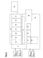
- the control device 1 shown in FIG. 1, in particular for controlling an injection molding machine, comprises a module carrier 2, which consists of stamped and formed sheet metal with different recesses 4, 8, 22. On this module carrier 2, the various elements of the controller are supported.
- a technology module housing 10 is shown schematically on the left side. In this there is a technology board 12. Through the open top of the technology module connections can be led away from the technology board 12. Preference will be given for the contacting mainly prefabricated plug contacts or plug in the manner of Frontsteckem, which are guided by the open top.
- a base 22 for an optional expansion module is provided to the left of the technology module housing 10 for an optional expansion module.
- the area of the module carrier 2 located at the rear right in FIG. 1 is designed as a so-called rack 6, on which plug-in modules 14, which are control modules, can be fastened via a latching mechanism.
- plug-in modules 14, which are control modules can be fastened via a latching mechanism.
- 6 Rastucunsaus traditions 8 are provided in the area of the rack.
- recesses 4 are provided in this area, through which the plug first type of control modules 14 can be performed.
- the control modules 14 are designed as compact control elements which provide a second contacting possibility via a plug contact 16, which is protected by a cover 18. On them LEDs can be provided for operation display and other functional elements.
- a CPU module 20 which claimed in FIG.
- a bus interface which establishes a connection to an external CPU, which performs the functions of a control module or a PLC.
- plug contacts of the first type 26 are provided in which the control modules 14 and the CPU module 20 can be inserted through the recesses 4.
- the bus board 24 also has at least one plug contact of the second type 28, via which a connection to the technology module or the technology board 12 can be made.
- a wiring board 30 is mounted on the back, on which a security interconnection and the wiring of the machine to be controlled and a voltage distribution for the control are provided substantially.
- Fig. 1 only schematically illustrated components and wiring connections can be guided through the recesses 4 in the module carrier 2.
- the wiring board 30 has a plug contact third type 32, via which it can be connected to the or the technology boards 12 and via this with the bus board. Not shown is provided on her voltage distribution for the whole controller.
- Fig. 2 shows the conceptual structure of the controller 1 according to the invention, the essential information flows are shown schematically with arrows in the boxes on the left in the figure.
- some control modules 14 are given with possible assignments. So z.
- Temperature 150, an analog-mixing module 140, a P-interface 130 for Wegmesssysteme or the like may be provided.
- At the unused slots 160 further control modules can be connected as needed.
- the CPU 20 or bus interface shown on the top right can be used to integrate further control modules, such as rare additional units 120, machine-type-dependent functions or other special options.
- the voltage distribution and protection 170 and 180 both for the entire control device 1 and for the control modules.
- the EN 201 module that includes the safety logic
- the safety circuit according to EN 201 arranged for the monitoring of safety doors, which ensures the safety of the machine in operation, as well as different assemblies 190, such as hardware relays, measuring points, safety relays and elements for fixed wiring like bridges, quenching elements and the like.
- the connections to the machine are usually made via pre-assembled cable sets, which reduces the susceptibility to wiring errors, increases clarity and minimizes the space required.
- the technology module 10, 12 located on the left between the control module area and the wiring board 30 in FIG. 2 comprises a basic PLC scope and essentially provides the input and output connections from the controller to the injection molding machine.
- the technology module may comprise one or more technology boards 12, which in the case of more than one board are connected to one another via transverse contacts, which are preferably designed for plugging.
- One task of the technology module is bridging, i. the connection, the wiring board 30 to the bus board 24.
- the technology module in the illustrated embodiment should comprise at least the following elements: 32 digital inputs, 24 2 A digital outputs, 8 0.7 A digital outputs, 7 analog temperature inputs, 1 KTY input for oil temperature, 4 analogue outputs of +/- 10 V, 3 analogue differential inputs of 0-10 V, 8 digital inputs that comply with the safety standard EN 201 and 4 transonic inputs.
- an interface card for P-type ultrasonic displacement measuring systems can be provided.
- the control device 1 can be used very flexibly for any machine series. This is additionally promoted by the fact that the plug-in contacts of the first type 26, which are provided for the connection of the control modules 14 to the bus board 24, are usable both for digital and for analog modules.
- an expansion module can be added to the technology module, for example with 8 0-10V analog outputs, 8 0-10V analog inputs, and 8 digital inputs and 8 digital outputs 2A has.
- This module consists essentially only of plug contacts for the inputs and outputs, an input protection circuit and output drivers, the control is taken over by the actual technology module.
Landscapes
- Engineering & Computer Science (AREA)
- Microelectronics & Electronic Packaging (AREA)
- Automation & Control Theory (AREA)
- Computer Networks & Wireless Communication (AREA)
- Programmable Controllers (AREA)
- Injection Moulding Of Plastics Or The Like (AREA)
- Coupling Device And Connection With Printed Circuit (AREA)
- Biological Treatment Of Waste Water (AREA)
- Diaphragms For Electromechanical Transducers (AREA)
Abstract
Description
Die vorliegende Erfindung betrifft eine Steuerungsvorrichtung für eine Maschine, wie sie insbesondere zum Steuern einer Spritzgießmaschine Anwendung findet.The present invention relates to a control device for a machine, as used in particular for controlling an injection molding machine.
Die Steuerungsvorrichtung einer Spritzgießmaschine ist gewöhnlicherweise modular aufgebaut, wobei verschiedene Module verschiedene Ansteueraufgaben übernehmen sowie die Verbindung mit bestimmten steuerbaren Einrichtungen der Spritzgießmaschine, wie z. B. Drucksensor und motorischem Antrieb herstellen. Diese Module sind über einen Rückwandbus miteinander verbunden und zumeist in ein sogenanntes "Rack" einsteckbar ausgeführt, auf dessen Rückseite eine sogenannte Bus-Platine mit einem Rückwandbus angebracht ist. Die Verbindung zwischen Modulen und Rückwandbus erfolgt meist über Steckkontakte. Ein Modul stellt bisher eine SPS (Speicherprogrammierbare Steuerung) zur Verfügung, in der eine Sicherheitslogik der Spritzgießmaschine hinterlegt ist. Daneben umfasst die Steuerungsvorrichtung eine sogenannte Verdrahtungsplatine, über die die Verdrahtung inklusive der Sicherheitsverschaltung der Maschine ausgeführt ist und die eine Spannungsverteilung für die Steuerungsvorrichtung bereitstellt. Die Verdrahtungsplatine stellt demgemäss die Spannungsverteilung mit Absicherungen, die Sicherheitsverschaltung inklusive eventueller Sicherheitsrelais sowie weitere Baugruppen zur Verfügung sowie einen möglichst großen Anteil der Verdrahtung der Maschine und ihre Sicherheitsverschaltung. Ein sogenanntes Technologiemodul, das fest auf der Verdrahtungsplatine angebracht ist, enthält einen Basisumfang für analoge und digitale Steuerungsein-/ausgangsverbindungen zu der Spritzgießmaschine. Die Verbindung zwischen den Steuerungsmodulen bzw. der Bus-Platine und auf der Verdrahtungsplatine vorgesehenen Baugruppen erfolgt separat über einzelne Kabel.The control device of an injection molding machine is usually modular, with different modules take on different control tasks and the connection with certain controllable devices of the injection molding machine, such as. B. pressure sensor and motor drive produce. These modules are connected to each other via a backplane bus and usually designed plug-in in a so-called "rack", on the back of a so-called bus board is mounted with a backplane bus. The connection between modules and backplane bus is usually via plug contacts. So far, one module has provided a PLC (programmable logic controller) in which a safety logic of the injection molding machine is stored. In addition, the control device comprises a so-called wiring board, via which the wiring is carried out including the safety connection of the machine and which provides a voltage distribution for the control device. Accordingly, the wiring board provides the voltage distribution with fuses, the safety interconnection including any safety relays and other modules as well as the largest possible share of the wiring of the machine and its safety interconnection. A so-called technology module fixedly mounted on the wiring board includes a base perimeter for analog and digital control input / output connections to the injection molding machine. The connection between the control modules or the bus board and provided on the wiring board assemblies is done separately via individual cables.
Bis jetzt war die Montage einer solchen Steuerung wegen der vielen separaten Bauteile sehr aufwendig und dadurch auch fehleranfällig. Insbesondere die separate Verdrahtung der einzelnen Einheiten der Verdrahtungsplatine mit den Steuerungsmodulen war unübersichtlich und stellte einen Risikofaktor dar. Bei einem Aufrüsten der Spritzgießmaschine und damit einer Zunahme der anzusteuernden Komponenten ergab sich das Problem einer adäquaten Ansteuerung durch die bestehende Steuerung. Ein weiterer Nachteil ergab sich daraus, dass jede Spritzgießmaschinen-Baureihe individuell verdrahtet werden musste.Until now, the assembly of such a controller was very complicated because of the many separate components and thus prone to error. In particular, the separate wiring of the individual units of the wiring board with the control modules was confusing and constituted a risk factor. In an upgrade of the injection molding machine and thus an increase in the components to be controlled, there was the problem of adequate control by the existing control. Another disadvantage resulted from the fact that each injection molding machine series had to be individually wired.
Aufgabe der vorliegenden Erfindung ist es, eine Steuerungsvorrichtung für eine Maschine zu schaffen, die durch Standardisierung eine Kostenreduzierung ermöglicht, zudem eine geringe Fehlerwahrscheinlichkeit aufweist, und dabei flexibel einsetzbar und möglichst kompakt gestaltet ist.Object of the present invention is to provide a control device for a machine that allows standardization by cost reduction, also has a low probability of error, and is flexible and compact as possible designed.
Diese Aufgabe wird durch eine Steuerungsvorrichtung entsprechend den Merkmalen des Anspruchs 1 gelöst.This object is achieved by a control device according to the features of
Entsprechend der vorliegenden Erfindung umfasst eine Steuerung für eine Maschine, wie sie insbesondere bei Spritzgießmaschinen zum Einsatz kommt, eine Bus-Platine, die Kommunikationsverbindungen zwischen verschiedenen Einheiten, bevorzugt gemäß einer lokalen Synchronbus- oder Feldbus-Architektur bereitstellt, eine Verdrahtungsplatine und ein separates Technologie-Modul. Dieses weist jeweils eine oder mehrere Technologie-Platinen auf, die einen Basisumfang für eine SPS (speicherprogrammierbare Steuerung) zur Verfügung stellen. Das Technologie-Modul ist nicht wie früher integral mit der Verdrahtungsplatine sondern als separates Bauteil ausgeführt, und weist Stecker zweiter bzw. dritter Art auf, über die es direkt mit der Bus-Platine bzw. der Verdrahtungsplatine verbindbar ist, und stellt so eine Brückung, d.h. eine Verbindung, zwischen diesen beiden Platinen her, wodurch sich die Verdrahtung zwischen diesen reduzieren lässt. Mindestens ein Steuerungsmodul, das Steuerungsaufgaben an der Maschine übernimmt, ist an die Bus-Platine über Steckkontakte erster Art einsteckbar gefertigt. Weitere Steuerungsmodule können nach Bedarf hinzugefügt werden. Die Steuerungsvorrichtung lässt sich also durch Hinzufügen von zusätzlichen Steuerungsmodulen leicht an unterschiedliche Maschinenanforderungen anpassen. Durch Verwendung von vorkonfektionierten Steckkontakten zum Verbinden der einzelnen Elemente der Steuerung untereinander ergibt sich eine Flexibilisierung im Entwurf der Steuerungsvorrichtung und der Verdrahtungsaufwand wird verringert. Dadurch lässt sich die Steuerung kompakt gestalten, und es kann Platz eingespart werden. Die Verwendung von vorkonfektionierten Bauteilen sorgt für eine zusätzliche Kostenreduzierung.In accordance with the present invention, a controller for a machine, such as that used in injection molding machines, comprises a bus board providing communication links between different units, preferably according to a local synchronous bus or fieldbus architecture, a wiring board, and a separate technology board. Module. This has in each case one or more technology boards, which provide a basic scope for a PLC (programmable logic controller). The technology module is not designed as integral with the wiring board but as a separate component, and has second or third type connector, via which it is directly connectable to the bus board or the wiring board, and thus provides a bridge, ie a connection between these two boards, which reduces the wiring between them. At least one control module that performs control tasks on the machine is made pluggable to the bus board via plug contacts of the first kind. Additional control modules can be added as needed. The control device can therefore be easily adapted to different machine requirements by adding additional control modules. By using prefabricated plug contacts for connecting the individual elements of the controller with each other there is a flexibility in the design of the control device and the wiring effort is reduced. This makes the controller compact and can save space. The use of prefabricated components provides an additional cost reduction.
Das Technologiemodul stellt unter anderem verschiedene digitale und/oder analoge Ein- und Ausgänge zur Verfügung, über die die Verbindung mit der Maschine hergestellt werden kann. Zusätzlich können spezielle Schnittstellen wie beispielsweise für ein EEPROM vorgesehen werden. Die Kontaktierung erfolgt bevorzugt über vorkonfektionierte Stecker.Among other things, the technology module provides various digital and / or analogue inputs and outputs via which the connection to the machine can be established. In addition, special interfaces such as for an EEPROM can be provided. The contacting is preferably via pre-assembled connector.
In einer besonders bevorzugten Ausführungsform ist als ein Steuerungsmodul ein CPU-Modul vorgesehen, das die Aufgaben einer SPS ausführt. Auch eine BusAnschaltung kann als ein Steuerungsmodul vorgesehen werden, die als Schnittstelle zu einer externen CPU dient, die dann die SPS-Aufgaben übernimmt oder den Leistungsumfang der SPS erweitert. Es ist allerdings auch möglich, direkt im Technologiemodul eine CPU für die Aufgaben der SPS vorzusehen, wodurch sich Steckplatz sparen lässt.In a particularly preferred embodiment, a CPU module is provided as a control module, which performs the tasks of a PLC. A bus connection can also be provided as a control module which serves as an interface to an external CPU, which then takes over the PLC tasks or extends the scope of the PLC. However, it is also possible to provide a CPU for the tasks of the PLC directly in the technology module, which saves slot space.
Die Verdrahtungsplatine umfasst im wesentlichen die Sicherheitsverschaltung der Maschine. So können beispielsweise Positionsschalter direkt angeschlossen werden, die nach der europäischen Norm EN 201 zur Überwachung von Schutztüren einer Spritzgießmaschine verwendet werden. Das für die Überwachung verwendete Programm, die sogenannte Sicherheitslogik, kann in einem nichtflüchtigen Speicher hinterlegt werden, wofür man ein sogenanntes EN 201 Modul einsetzt. Dieses Modul wird bevorzugt auf der Verdrahtungsplatine vorgesehenen, kann aber auch im Technologiemodul angesiedelt sein. Bevorzugt umfasst es neben dem nichtflüchtigen Speicher einen eigenen Controller, der die Sicherheitslogik abarbeitet und beispielsweise über einen 8 Bit-Bus mit der SPS der Maschine verbunden ist. Über eigene Ausgänge bedient das Modul die Sicherheitsverschaltung der zu steuernden Maschine und gewährleistet somit die Einhaltung der Sicherheitsvorschriften durch die von der erfindungsgemäßen Steuerungsvorrichtung gesteuerte Maschine. So können beispielsweise verschiedene Spannungsversorgungen zu Digitalausgängen für die Maschine im nichtsicheren Zustand hardwaremäßig über auf der Verdrahtungsplatine integrierte Sicherheitsrelais abgeschaltet werden.The wiring board essentially comprises the safety connection of the machine. For example, position switches can be directly connected, which are used to monitor the safety doors of an injection molding machine in accordance with the European standard EN 201. The program used for the monitoring, the so-called safety logic, can be stored in a non-volatile memory, for which a so-called EN 201 module is used. This module is preferably provided on the wiring board, but may also be located in the technology module. In addition to the non-volatile memory, it preferably includes its own controller, which processes the safety logic and is connected, for example, via an 8-bit bus to the PLC of the machine. Via its own outputs, the module operates the safety connection of the machine to be controlled and thus ensures compliance with the safety regulations by the machine controlled by the control device according to the invention. Thus, for example, different power supplies to digital outputs for the machine in the non-safe state can be switched off in hardware via safety relays integrated on the wiring board.
Des weiteren stellt die Verdrahtungsplatine eine Standardverdrahtung zu der zu steuernden Maschine, die bevorzugt über Steckverbinder erfolgt, und die Spannungsverteilung für die gesamte Steuerungsvorrichtung zur Verfügung. Die Platine ist bevorzugt so ausgelegt, dass die vorgesehene Sicherheitsverschaltung entsprechend den Baureihen bzw. gewählten Optionen erweiterbar ist. Die einzelnen auf der Verdrahtungsplatine vorgesehenen Bauteile werden soweit möglich durch vorkonfektionierte Kabelsätze über Stecker kontaktiert. Vorteilhafterweise können direkt an den Steckkontakten die Signale gemessen werden. Hierbei werden Größen, die häufig gemessen werden, bevorzugt auf einen 37 poligen D-Sub-Stecker zusammengefasst. Zu den auf der Verdrahtungsplatine vorgesehenen Bauteilen zählen beispielsweise Hardware-Relais, Sicherheits-Relais, EEPROM's für den Maschinenspeicher und unterschiedliche Messpunkte.Furthermore, the wiring board provides a standard wiring to the machine to be controlled, which preferably takes place via connectors, and the voltage distribution for the entire control device available. The board is preferably designed so that the intended safety connection can be extended according to the series or selected options. The individual provided on the wiring board components are contacted as far as possible by pre-assembled cable harnesses via plug. Advantageously, the signals can be measured directly on the plug contacts. Here are sizes that are frequently measured, preferably summarized on a 37-pin D-Sub connector. The components provided on the wiring board include, for example, hardware relays, safety relays, EEPROMs for the machine memory, and various measurement points.
Jedoch kann auch das Technologiemodul einen nichtflüchtigen Speicher mit einer Sicherheitslogik sowie einen Controller umfassen, auf dem die Sicherheitslogik läuft, die im wesentlichen die auf der Verdrahtungsplatine angeordnete Sicherheitsverschaltung der zu steuernden Maschine bedient und somit die Einhaltung der Sicherheitsvorschriften durch die von der erfindungsgemäßen Steuerung gesteuerte Maschine gewährleistet.However, the technology module may also comprise a nonvolatile memory with a safety logic and a controller running the safety logic, which essentially operates the safety circuit of the machine to be controlled arranged on the wiring board and thus compliance with the safety regulations by the machine controlled by the control according to the invention guaranteed.
Gemäß der vorliegenden Erfindung ist das Technologiemodul durch ein oder mehrere Erweiterungsmodule beliebig erweiterbar, um auch für Maschinen höherer Komplexität einsetzbar zu sein. Dieses Erweiterungsmodul stellt zusätzliche Eingangs- bzw. Ausgangs-Baugruppen bereit und verfügt über eine Eingangsschutzschaltung und Ausgangstreiber, die Ansteuerung wird von dem Technologiemodul übernommen.According to the present invention, the technology module can be expanded as desired by one or more expansion modules, so that it can also be used for machines of higher complexity. This expansion module provides additional input or output modules and has an input protection circuit and output driver, the control is taken over by the technology module.
Um die Steuerung besonders kompakt zu gestalten, können die Bus-Platine und die Verdrahtungsplatine vorteilhaft auf getrennten Bereichen einer einzigen Platine integral ausgebildet sein.In order to make the control particularly compact, the bus board and the wiring board may advantageously be integrally formed on separate areas of a single board.
Für die Halterung der erfindungsgemäßen Steuerung ist bevorzugt ein Modulträger vorgesehen, an dem die Bus-Platine, die Verdrahtungsplatine und das Technologiemodul sowie eventuelle Erweiterungsmodule befestigbar sind. Hierbei ist es besonders vorteilhaft, wenn die Platine bzw. die Platinen des Technologiemoduls so am Modulträger gehaltert sind, dass sie senkrecht zu der integral ausgeführten Platine bzw. zu den Platinen des Busses und der Verdrahtung angeordnet ist bzw. sind. Diese letzteren Platinen werden im wesentlichen planparallel zum Halter gelagert werden.For the mounting of the controller according to the invention, a module carrier is preferably provided, on which the bus board, the wiring board and the technology module and any expansion modules can be fastened. This is special advantageous if the board or the boards of the technology module are mounted on the module carrier, that it is perpendicular to the integrally formed board or to the boards of the bus and the wiring is or are. These latter boards will be stored substantially plane-parallel to the holder.
Die Bus-Platine und die Verdrahtungsplatine werden bevorzugt auf einer hinteren Seite des Modulträgers befestigt, während das Technologiemodul auf einer Vorderseite des Modulträgers angebracht ist, da so die auf diesem vorgesehen Ein-/Ausgangsverbindungen zu der anzusteuernden Maschine leichter zugänglich sind. Der Modulträger weist bevorzugt Ausnehmungen auf, durch die die Steckkontakte zwischen verschiedenen Modulen bzw. Platinen, d. h. zwischen den Steuerungsmodulen und der Bus-Platine sowie zwischen der Bus-Platine bzw. Verdrahtungsplatine und dem Technologiemodul führbar sind. Ausnehmungen über der Verdrahtungsplatine erlauben das direkte Durchführen der Verbindungen der Sicherheitsverschaltung. Zusätzlich sollte der Modulträger nach Art eines "Racks" weitere Ausnehmungen aufweisen, in die die Steuerungsmodule einrastbar ausgeführt sind. Die Module können dann ohne großen Aufwand durch einfaches Einrasten bevorzugt an der Vorderseite des Modulträgers befestigt werden, wobei gleichzeitig über Stecker und Steckkontakte erster Art, die durch die zuerst genannten Ausnehmungen greifen, eine Verbindung zwischen den Steuerungsmodulen und der Bus-Platine hergestellt wird.The bus board and the wiring board are preferably mounted on a rear side of the module carrier, while the technology module is mounted on a front side of the module carrier, as this is easier to access on this provided input / output connections to the machine to be controlled. The module carrier preferably has recesses through which the plug contacts between different modules or boards, d. H. between the control modules and the bus board and between the bus board or wiring board and the technology module are feasible. Recesses above the wiring board allow direct connection of the security interconnection. In addition, the module carrier should have further recesses in the manner of a "rack" into which the control modules are designed latchable. The modules can then be easily attached by simple snap on the front of the module carrier, at the same time via connectors and plug contacts of the first kind, which engage through the first-mentioned recesses, a connection between the control modules and the bus board is made.
Bevorzugt sind auf dem Modulträger einer erfindungsgemäßen Steuerung bereits Sockel für eventuelle Erweiterungsmodule des Technologiemoduls vorgesehen. Hierdurch kann der Umfang an Ein-/Ausgangsverbindungen zwischen Spritzgießmaschine und Steuerung erweitert werden. Um die erfindungsgemäße Steuerung noch kompakter und flexibler im Einsatz zu gestalten, können die Ein-/Ausgangsverbindungen des Technologiemoduls bzw. seiner Erweiterungsmodule durch vorkonfektionierte Frontstecker hergestellt werden.Sockets for possible expansion modules of the technology module are preferably already provided on the module carrier of a controller according to the invention. As a result, the scope of input / output connections between injection molding machine and control can be extended. In order to make the control according to the invention even more compact and flexible in use, the input / output connections of the technology module or its expansion modules can be produced by prefabricated front connectors.
Die Steckverbindungen erster Art, die die Verbindung der Steuerungsmodule mit der Bus-Platine herstellen, sind bevorzugt vorkonfektioniert und so ausgebildet, dass sie sowohl für digitale als auch für analoge Baugruppen einsetzbar sind.The connectors of the first type, which establish the connection of the control modules to the bus board, are preferably prefabricated and designed so that they can be used both for digital and for analog modules.
Bei Verwendung von mehreren Technologie-Platinen im Technologiemodul wird die Verbindung zwischen den Technologie-Platinen vorzugsweise über eine Querverbindung hergestellt, und nur eine der Platinen verfügt über einen Stecker zweiter bzw. dritter Art, der sie und die weiteren Platinen mit der Bus-Platine bzw. der Verdrahtungsplatine verbindet. Ähnlich sieht es bei der Verwendung von Erweiterungsmodulen aus, die ebenfalls nicht direkt mit den Platinen verbunden sind, sondern beispielsweise mittels einer Querverbindung über das Technologiemodul Kontakt zur diesen haben.When using multiple technology boards in the technology module, the connection between the technology boards is preferably made via a cross-connection, and only one of the boards has a second or third type connector, which they and the other boards with the bus board or the wiring board connects. The situation is similar when using extension modules which are likewise not directly connected to the boards, but instead, for example, have contact with them via a cross-connection via the technology module.
Für die Ansteuerung der einzelnen Elemente der Steuerung wird bevorzugt ein Hochgeschwindigkeits-Feldbussystem eingesetzt, das eine Multi-point-Verbindung auf der Bus-Platine bereitstellt.For the control of the individual elements of the controller, a high-speed fieldbus system is preferably used, which provides a multi-point connection on the bus board.
Durch die vorliegende Erfindung ist es gelungen, die Schnittstelle zwischen Steuerung und Leistung der Verdrahtungsplatine durch Einsatz einer separaten Technologieplatine zu standardisieren. Das Technologie-Modul stellt die Brückung, d.h. die Verbindung, zwischen Verdrahtungsplatine und Bus-Platine her. Um die Flexibilität der Steuerungsvorrichtung im Einsatz weiter zu erhöhen, können auf der Verdrahtungsplatine weitere Sockel für Zusatzeinheiten wie Relais vorgesehen sein, während auf der Bus-Platine beliebige Steuerungsmodule einsteckbar sind. Außerdem können diverse Wegmesssysteme, z. B. unter Einsatz von P-Schnittstellen und Potentiometern eingesetzt werden. Auch ist es möglich die Zylindererkennung auf aktuelle Bedürfnisse auszulegen und hierfür mehrere Eingänge oder vorkonfektionierte Steckverbindungen zur Datenübertragung zu benutzen. Hierdurch kann die Schnittstelle zum Zylinder der Spritzgießmaschine vereinheitlicht werden. Durch die Modularität und Flexibilität ist die Steuerungsvorrichtung gemäß der vorliegenden Erfindung für diverse Baureihen einsetzbar und leicht anpassbar.The present invention has succeeded in standardizing the interface between control and power of the wiring board by using a separate technology board. The technology module provides the bridge, i. the connection, between the wiring board and the bus board. In order to further increase the flexibility of the control device in use, further sockets for additional units such as relays can be provided on the wiring board, while any control modules can be inserted on the bus board. In addition, various Wegmesssysteme, z. B. be used using P-interfaces and potentiometers. It is also possible to design the cylinder detection for current needs and to use multiple inputs or pre-assembled connectors for data transmission. As a result, the interface to the cylinder of the injection molding machine can be standardized. Due to the modularity and flexibility of the control device according to the present invention for various series can be used and easily adaptable.
Beispielhaft soll eine Ausführungsform einer erfindungsgemäßen Steuerung anhand der folgenden Zeichnungen beschrieben werden. Es zeigen:
- Fig. 1
- eine schematische Draufsicht auf eine Ausführungsform der erfindungsgemäßen Steuerung und
- Fig. 2
- eine schematische Funktionsaufgliederung der Steuerung gemäß Fig. 1.
- Fig. 1
- a schematic plan view of an embodiment of the inventive control and
- Fig. 2
- a schematic functional breakdown of the controller of FIG. 1.
Die in Fig. 1 dargestellte Steuerungsvorrichtung 1, insbesondere zum Steuern einer Spritzgießmaschine, umfasst einen Modulträger 2, der aus gestanztem und geformtem Blech mit unterschiedlichen Ausnehmungen 4, 8, 22 besteht. Auf diesem Modulträger 2 sind die verschiedenen Elemente der Steuerung gehaltert. In Fig. 1 ist auf der linken Seite ein Technologiemodulgehäuse 10 schematisch dargestellt. In diesem befindet sich eine Technologie-Platine 12. Durch die offene Oberseite des Technologiemoduls können Anschlüsse von der Technologie-Platine 12 weggeführt werden. Bevorzugt wird man für die Kontaktierung hauptsächlich vorkonfektionierte Steckkontakte bzw. Stecker in der Art von Frontsteckem vorsehen, die durch die offene Oberseite geführt werden. Links neben dem Technologiemodulgehäuse 10 befindet sich ein Sockel 22 für ein optionales Erweiterungsmodul.The
Der in Fig. 1 hinten rechts gelegene Bereich des Modulträgers 2 ist als sogenanntes Rack 6 ausgebildet, auf dem Steckmodule 14, bei denen es sich um Steuerungsmodule handelt, über einen Einrastmechanismus befestigt werden können. Hierfür sind im Bereich des Racks 6 Rastverbindungsausnehmungen 8 vorgesehen. Ebenfalls sind in diesem Bereich Ausnehmungen 4 vorgesehen, durch die die Stecker erster Art der Steuerungsmodule 14 geführt werden können. Im vorliegenden Fall sind die Steuerungsmodule 14 als Kompaktsteuerungselemente ausgeführt, die eine zweite Kontaktierungsmöglichkeit über einen Steckkontakt 16 bereitstellen, der durch eine Abdeckhaube 18 geschützt wird. An ihnen können LED's zur Betriebsanzeige sowie andere Funktionselemente vorgesehen sein. Im Bereich des Racks 6 ist außerdem ein CPU-Modul 20, das in der Fig. 1 zwei Steckplätze beansprucht, oder alternativ eine Busanschaltung vorgesehen, die eine Verbindung zu einer externen CPU herstellt, die die Funktionen eines Steuerungsmoduls bzw. einer SPS übemimmt. Die Verbindung zwischen dem CPU-Modul 20 bzw. der Busansteuerung und den anderen Steuerungsmodulen 14 erfolgt über eine auf der Rückseite des Modulträgers 2 im Bereich des Racks 6 angeordnete Bus-Platine 24. Auf dieser Bus-Platine 24 sind Steckkontakte erster Art 26 vorgesehen, in die die Steuerungsmodule 14 bzw. das CPU-Modul 20 durch die Ausnehmungen 4 eingesteckt werden können. Die Bus-Platine 24 verfügt auch über mindestens einen Steckkontakt zweiter Art 28, über den eine Verbindung zu dem Technologiemodul bzw. der Technologie-Platine 12 hergestellt werden kann.The area of the
Im gemäß der Fig. 1 vorderen rechten Bereich des Modulträgers 2 der erfindungsgemäßen Steuerung 1 ist rückseitig eine Verdrahtungsplatine 30 angebracht, auf der im wesentlichen eine Sicherheitsverschaltung sowie die Verdrahtung der zu steuernden Maschine sowie eine Spannungsverteilung für die Steuerung vorgesehen sind. Auf dieser angeordnete, in der Fig. 1 nur schematisch dargestellte Bauteile sowie Verdrahtungsverbindungen können durch die Ausnehmungen 4 im Modulträger 2 geführt werden. Ferner verfügt die Verdrahtungsplatine 30 über einen Steckkontakt dritter Art 32, über den sie mit der bzw. den Technologie-Platinen 12 und über diese mit der Bus-Platine verbunden werden kann. Nicht dargestellt ist die auf ihr vorgesehene Spannungsverteilung für die ganze Steuerung.1 front panel of the
Fig. 2 zeigt den konzeptionellen Aufbau der erfindungsgemäßen Steuerung 1, die wesentlichen Informationsflüsse sind schematisch mit Pfeilen in den Kästen links in der Figur dargestellt. Im oberen Bereich sind einige Steuerungsmodule 14 mit möglichen Belegungen angegeben. So können z. B. ein sog. Temperatur- 150, ein A-nalogmischmodul 140 , eine P-Schnittstelle 130 für Wegmesssysteme oder ähnliches vorgesehen sein. An den nicht belegten Steckplätzen 160 können nach Bedarf weitere Steuerungsmodule verbunden werden. Über die oben rechts gezeigte CPU 20 oder Busanschaltung können weitere Steuerungsmodule eingebunden werden, wie beispielsweise seltene Zusatzeinheiten 120, maschinentypabhängige Funktionen oder sonstige Sonderoptionen.Fig. 2 shows the conceptual structure of the
Auf der in Fig. 2 unten dargestellten Verdrahtungsplatine 30 befindet sich die Spannungsverteilung und Absicherung 170 bzw. 180 sowohl für die gesamte Steuerungsvorrichtung 1 als auch für die Steuerungsmodule. Hier sind das die Sicherheitslogik umfassende EN 201 Modul, die Sicherheitsverschaltung gemäß EN 201 für die Überwachung von Schutztüren angeordnet, die die Sicherheit der Maschine im Betrieb gewährleistet, sowie unterschiedliche Baugruppen 190, beispielsweise Hardware-Relais, Messpunkte, Sicherheitsrelais und Elemente für die feste Verdrahtung wie Brücken, Löschglieder und ähnliches. Die Verbindungen zur Maschine erfolgen meist über vorkonfektionierte Kabelsätze, was die Fehleranfälligkeit bei der Verdrahtung reduziert, die Übersichtlichkeit erhöht und den benötigten Platz minimiert.On the
Das in Fig. 2 links zwischen dem Steuerungsmodulbereich und der Verdrahtungsplatine 30 angeordnete Technologiemodul 10, 12 umfasst einen SPS-Basisumfang und stellt im wesentlichen die Eingangs- und Ausgangsverbindungen von der Steuerung zu der Spritzgießmaschine bereit. Das Technologiemodul kann eine oder mehrere Technologie-Platinen 12 umfassen, wobei diese im Fall von mehr als einer Platine untereinander über Querkontakte verbunden werden, die bevorzugt zum Stecken ausgeführt sind. Eine Aufgabe des Technologiemoduls ist die Brückung, d.h. die Verbindung, der Verdrahtungsplatine 30 mit der Bus-Platine 24. Das Technologiemodul sollte in der dargestellten Ausführungsform zumindest folgende Elemente umfassen: 32 digitale Eingänge, 24 digitale Ausgänge mit 2 A-Beaufschlagung, 8 digitale Ausgänge mit 0,7 A-Beaufschlagung, 7 analoge Temperatureingänge, 1 KTY-Eingang für Öltemperatur, 4 analoge Ausgänge von +/-10 V, 3 analoge Differenz-Eingänge von 0-10 V, 8 digitale Eingänge, die der Sicherheitsnorm EN 201 entsprechen, sowie 4 Transsonareingänge. Zusätzlich kann eine Interface-Karte für Ultraschall-Wegmesssysteme mit P-Schnittstelle vorgesehen sein.The
Durch die Modularität der erfindungsgemäßen Steuerung 1, d. h. insbesondere durch die Möglichkeit, beliebige Steuerungsmodule 14 auf dem Rack hinzuzufügen, wobei jedoch ein vorgegebener Platzbedarf für die Gesamtsteuerung nicht überschritten wird, die durch Einsatz des erfindungsgemäßen Technologie-Moduls 12 standardisierte Brückung von Bus- 24 und Verdrahtungs-Platine 30 und die Erweiterbarkeit des Technologiemoduls 12, lässt sich die Steuerungsvorrichtung 1 für beliebige Maschinen-Baureihen sehr flexibel einsetzen. Dies wird zusätzlich dadurch gefördert, dass die Steckkontakte erster Art 26, die für den Anschluss der Steuerungsmodule 14 an die Bus-Platine 24 vorgesehen sind, sowohl für digitale als auch für analoge Baugruppen verwendbar sind.Due to the modularity of the
Um bei höher funktionalen Maschinen eine kostenoptimale Erweiterung der Steuerungsvorrichtung durchführen zu können, kann an das Technologiemodul eine Erweiterungsbaugruppe angefügt werden, die beispielsweise über 8 analoge Ausgänge von 0-10V, 8 analoge Eingänge von 0-10V sowie 8 digitale Eingänge und 8 digitale Ausgänge von 2A verfügt. Diese Baugruppe besteht im wesentlichen nur noch aus Steckkontakten für die Ein- und Ausgänge, einer Eingangsschutzschaltung sowie Ausgangstreibern, die Ansteuerung wird vom eigentlichen Technologiemodul übemommen.In order to be able to carry out cost-effective expansion of the control device for higher-functional machines, an expansion module can be added to the technology module, for example with 8 0-10V analog outputs, 8 0-10V analog inputs, and 8 digital inputs and 8 digital outputs 2A has. This module consists essentially only of plug contacts for the inputs and outputs, an input protection circuit and output drivers, the control is taken over by the actual technology module.
Die Vorteile der vorliegenden Erfindung sind also in der Vereinheitlichung bei gleichzeitiger Erhöhung der Flexibilität einer modularen Steuerungsvorrichtung zu sehen, was zu Kostenreduzierung und Platzersparnis im Schaltschrank führt, und zudem den Vorteil hat, dass die Steuerung universell einsetzbar und dennoch an die jeweilige Bedürfnisse anpassbar ist.The advantages of the present invention are thus to be seen in the standardization while increasing the flexibility of a modular control device, resulting in cost reduction and space savings in the cabinet, and also has the advantage that the controller is universally applicable and yet adaptable to the particular needs.
- 11
- Steuerungcontrol
- 22
- Modulträgermodule carrier
- 44
- Ausnehmungenrecesses
- 66
- Rackrack
- 88th
- RastverbindungsausnehmungenRastverbindungsausnehmungen
- 1010
- TechnologiemodulgehäuseTechnology module housing
- 1212
- Technologie-PlatineTechnology circuit board
- 1414
- Steuerungsmodulcontrol module
- 1616
- Steckkontaktplug contact
- 1818
- Abdeckhaubecover
- 2020
- CPU-ModulCPU module
- 2222
- Sockel für ErweiterungsmodulSocket for expansion module
- 2424
- Bus-PlatineBus board
- 2626
- Steckkontakt erster ArtPlug contact of the first kind
- 2828
- Steckkontakt zweiter ArtPlug contact of the second kind
- 3030
- Verdrahtungsplatinewiring board
- 3232
- Steckkontakt dritter ArtPlug contact third type
- 120120
- Zusatzeinheitenadditional units
- 130130
- P-SchnittstelleP interface
- 140140
- Analog MischmodulAnalog mixing module
- 150150
- Temperaturmodultemperature module
- 160160
- ReservesteckplatzReserve slot
- 170170
- Spannungsverteilung SteuerungVoltage distribution control
- 180180
- Spannungsverteilung MaschineStress distribution machine
- 190190
- Baugruppenassemblies
Claims (19)
- A control device (1) for controlling a machine, especially an injection moulding machine, comprising:- a bus board (24) which provides a multi-point connection via a bus system and which has at least one plug-in contact (26) of a first type, into which respectively one control module (14) can be plugged and at least one plug-in contact of a second type (28) into which a process-oriented board (12) can be plugged,- at least one control module (14) comprising a plug of the first type complementary to the plug-in contact of the first type for taking over control functions at the machine,- a wiring board (30) which can be connected by means of a plug-in contact of a third type (32) to the process-oriented board or boards (12) and- at least one process-oriented module which comprises respectively one or a plurality of process-oriented boards (12) of which at least one can be connected to the bus board (24) by means of a plug of the second type complementary to the plug-in contact of the second type (28) and to the wiring board (30) by means of a plug of the third type complementary to the plug-in contact of the third type (32), which comprises or comprise a base circumference of input/output connections to the machine to be controlled and makes a connection between bus board (24) and wiring board (30).
- The control device according to claim 1,
wherein a CPU module (20) is provided as a control module. - The control device according to claim 1 or claim 2,
wherein a bus connection to an external CPU is provided as a control module. - The control device according to any one of claims 1 to 3, wherein the wiring board (30) substantially comprises a safety interconnection, wiring of the machine to be controlled and a voltage distribution.
- The control device according to claim 4,
wherein the wiring board (30) comprises a non-volatile memory with safety logic and a controller which operates the safety interconnection. - The control device according to claim 4,
wherein the process-oriented board comprises a non-volatile memory with safety logic and a controller which operates the safety interconnection arranged on the wiring board (30). - The control device according to any one of claims 1 to 6, wherein the process-oriented board has a CPU for executing the tasks of the SPC.
- The control device according to any one of claims 1 to 7, wherein the process-oriented board comprises an extension module which has additional input or output assemblies, output drivers and/or input protection circuitry.
- The control device according to any one of claims 1 to 8, wherein the wiring board (30) and the bus board (24) are integrally constructed on separate areas of a single board.
- The control device according to any one of claims 1 to 9, wherein a module carrier (2) is provided on which the process-oriented board, the wiring board (30) and the bus board (24) are fixed.
- The control device according to claim 10, wherein the board or the boards (12) of the process-oriented module is or are arranged on the module carrier (2) perpendicular to the wiring board (30) and the bus board (24).
- The control device according to any one of claims 10 or 11, wherein the wiring board (30) and the bus board (24) are fixed on a rear side of the module carrier (2) and the process-oriented module is fixed on a front side of the module carrier (2).
- The control device according to any one of claims 10 to 12, wherein the module carrier (2) has recesses (4) through which the plug-in contacts are guided between the various modules (16) or boards (12, 24, 30) as well as single components arranged on the wiring board (30).
- The control device according to any one of claims 10 to 13, wherein the module carrier (2) additionally has locking connection recesses (8) into which the control modules (14) engage.
- The control device according to any one of claims 10 to 14, wherein sockets (22) for one or more extension modules of the process-oriented module are provided on the module carrier (2).
- The control device according to any one of claims 1 to 15, wherein the input/output connections of the process-oriented module or its extension modules are made by pre-assembled front plugs.
- The control device according to any one of claims 1 to 16, wherein the plug-in contacts of the first type (26) are pre-assembled and are constructed such that they make a plug connection for digital and also for analog assemblies.
- The control device according to any one of claims 10 to 17, wherein the boards (12) of the process-oriented module are coupled by a cross-connection.
- The control device according to any one of claims 10 to 18, wherein the module carrier (2) consists of sheet metal.
Applications Claiming Priority (3)
| Application Number | Priority Date | Filing Date | Title |
|---|---|---|---|
| DE10259415 | 2002-12-19 | ||
| DE10259415A DE10259415A1 (en) | 2002-12-19 | 2002-12-19 | Technology board with modular PLC integration and expansion |
| PCT/EP2003/012111 WO2004057937A1 (en) | 2002-12-19 | 2003-10-31 | Process-oriented board with modular spc integration and expansion |
Publications (2)
| Publication Number | Publication Date |
|---|---|
| EP1576867A1 EP1576867A1 (en) | 2005-09-21 |
| EP1576867B1 true EP1576867B1 (en) | 2006-05-03 |
Family
ID=32477779
Family Applications (1)
| Application Number | Title | Priority Date | Filing Date |
|---|---|---|---|
| EP03813552A Expired - Lifetime EP1576867B1 (en) | 2002-12-19 | 2003-10-31 | Process-oriented board with modular spc integration and expansion |
Country Status (10)
| Country | Link |
|---|---|
| US (1) | US7286899B2 (en) |
| EP (1) | EP1576867B1 (en) |
| KR (1) | KR100676579B1 (en) |
| CN (1) | CN100428874C (en) |
| AT (1) | ATE325526T1 (en) |
| AU (1) | AU2003303101A1 (en) |
| CA (1) | CA2505376A1 (en) |
| DE (2) | DE10259415A1 (en) |
| RU (1) | RU2313200C2 (en) |
| WO (1) | WO2004057937A1 (en) |
Families Citing this family (11)
| Publication number | Priority date | Publication date | Assignee | Title |
|---|---|---|---|---|
| DE102006010908B4 (en) * | 2006-03-09 | 2010-01-14 | Audi Ag | Device for holding at least one relay |
| IT1391799B1 (en) * | 2008-11-21 | 2012-01-27 | Sirti Spa | METHOD AND SYSTEM FOR THE PROTECTION OF AN ELECTRIC LINE FOR RAILWAY SIGNALS |
| FR2940589B1 (en) * | 2008-12-24 | 2011-01-14 | Sagem Defense Securite | MODULAR ELECTRIC CARD FOR POWER COMPONENTS. |
| US8705863B1 (en) * | 2010-06-15 | 2014-04-22 | Encela Technologies LLC | Method and system for providing a computer implemented control system for an automated system |
| SG180052A1 (en) | 2010-10-28 | 2012-05-30 | Rockwell Automation Asia Pacific Business Ctr Pte Ltd | Programmable controller component with assembly alignment features |
| DE102011101686B4 (en) * | 2011-05-16 | 2013-02-21 | Phoenix Contact Gmbh & Co. Kg | System cabling for multiple relay arrangement |
| DE102014212969A1 (en) * | 2014-07-03 | 2016-01-07 | Bender Gmbh & Co. Kg | Bus connector system for electrical equipment |
| DE102018133646A1 (en) | 2018-12-28 | 2020-07-02 | Beckhoff Automation Gmbh | Basic module and function module for a control cabinet system |
| DE102018133657A1 (en) | 2018-12-28 | 2020-07-02 | Beckhoff Automation Gmbh | BASIC MODULE AND FUNCTIONAL MODULE FOR A CONTROL CABINET SYSTEM AND CONTROL CABINET SYSTEM |
| DE102018133647A1 (en) * | 2018-12-28 | 2020-07-02 | Beckhoff Automation Gmbh | Control cabinet system consisting of basic module and function modules as well as function module |
| DE102019106082B4 (en) | 2019-03-11 | 2021-06-24 | Beckhoff Automation Gmbh | CABINET SYSTEM WITH SEAL INSERT |
Family Cites Families (14)
| Publication number | Priority date | Publication date | Assignee | Title |
|---|---|---|---|---|
| US3566190A (en) * | 1968-12-23 | 1971-02-23 | Raven Ind Inc | Industrial control system with means for releasably securing a plurality of electronic modules |
| FR2589286B1 (en) | 1985-10-25 | 1988-05-13 | Cit Alcatel | ORTHOGONAL PRINTED CIRCUIT BOARD INTERCONNECTION ASSEMBLY AND SWITCHING NETWORKS USING THE SAME |
| US5007846A (en) * | 1990-06-11 | 1991-04-16 | Gonen Ravid | Specialized frame for retaining an edge connector on a printed circuit board |
| DE9200939U1 (en) | 1992-01-28 | 1992-03-19 | Telenorma Gmbh, 6000 Frankfurt, De | |
| SE501791C2 (en) * | 1993-09-23 | 1995-05-15 | Ellemtel Utvecklings Ab | Device with a backplane adapted for cooperation with a number of circuit boards |
| US5591366A (en) | 1994-06-23 | 1997-01-07 | Husky Injection Molding Systems Ltd. | Injection molding heater including circuit breaking means |
| DE19615093C2 (en) * | 1996-04-17 | 2003-04-24 | Schneider Automation Gmbh | automation equipment |
| US5984734A (en) * | 1997-04-30 | 1999-11-16 | Westinghouse Process Control, Inc. | Modular input/output system with flexible interface with field wiring |
| US5808876A (en) | 1997-06-20 | 1998-09-15 | International Business Machines Corporation | Multi-function power distribution system |
| US6356454B1 (en) | 1997-09-15 | 2002-03-12 | Siemens Aktiengesellschaft | Electrical unit having an aligning element |
| DE19748531A1 (en) * | 1997-11-03 | 1999-05-06 | Siemens Ag | Assembly system for load feeders with permanent wiring |
| DE29901194U1 (en) | 1999-01-25 | 1999-05-20 | Weidmueller Interface | Bus conductor section for an electrical device |
| JP3080617B1 (en) | 1999-07-19 | 2000-08-28 | ファナック株式会社 | Mold protection device for injection molding machine |
| CN2469660Y (en) * | 2001-02-15 | 2002-01-02 | 北京四方同创保护与控制设备有限公司 | Connecting component used for connecting bus-plate, connector and output terminal |
-
2002
- 2002-12-19 DE DE10259415A patent/DE10259415A1/en not_active Withdrawn
-
2003
- 2003-10-31 WO PCT/EP2003/012111 patent/WO2004057937A1/en not_active Application Discontinuation
- 2003-10-31 EP EP03813552A patent/EP1576867B1/en not_active Expired - Lifetime
- 2003-10-31 DE DE50303258T patent/DE50303258D1/en not_active Expired - Lifetime
- 2003-10-31 RU RU2005122649/09A patent/RU2313200C2/en active
- 2003-10-31 CA CA002505376A patent/CA2505376A1/en not_active Abandoned
- 2003-10-31 CN CNB2003801035525A patent/CN100428874C/en not_active Expired - Lifetime
- 2003-10-31 KR KR1020057011249A patent/KR100676579B1/en not_active IP Right Cessation
- 2003-10-31 AT AT03813552T patent/ATE325526T1/en active
- 2003-10-31 AU AU2003303101A patent/AU2003303101A1/en not_active Abandoned
-
2005
- 2005-06-09 US US11/148,883 patent/US7286899B2/en not_active Expired - Fee Related
Also Published As
| Publication number | Publication date |
|---|---|
| RU2005122649A (en) | 2006-01-20 |
| CN100428874C (en) | 2008-10-22 |
| CN1714610A (en) | 2005-12-28 |
| RU2313200C2 (en) | 2007-12-20 |
| WO2004057937A1 (en) | 2004-07-08 |
| US7286899B2 (en) | 2007-10-23 |
| DE50303258D1 (en) | 2006-06-08 |
| KR100676579B1 (en) | 2007-01-30 |
| DE10259415A1 (en) | 2004-07-08 |
| KR20050084397A (en) | 2005-08-26 |
| AU2003303101A1 (en) | 2004-07-14 |
| EP1576867A1 (en) | 2005-09-21 |
| CA2505376A1 (en) | 2004-07-08 |
| US20050228507A1 (en) | 2005-10-13 |
| ATE325526T1 (en) | 2006-06-15 |
Similar Documents
| Publication | Publication Date | Title |
|---|---|---|
| EP1815728B1 (en) | Modular automation system | |
| DE102015216310B4 (en) | Vehicle power control system, wire harness, and vehicle power control device | |
| EP1174781B1 (en) | Signal transmission apparatus | |
| EP1840682A1 (en) | Electrical field device and extension module for plugging in to said electric field device | |
| EP1576867B1 (en) | Process-oriented board with modular spc integration and expansion | |
| EP2258153B1 (en) | Electric modular system comprising a multi-functional field bus module | |
| EP2510412B1 (en) | Electronic assembly | |
| DE4133636C2 (en) | ||
| DE10231950B4 (en) | Control circuit for configuring at least one input / output module plug pin, input / output module, programmable logic control circuit PLC, and method for configuring at least one input / output module plug pin using a control circuit | |
| EP3251215B1 (en) | Controller for a multi-voltage on-board power supply | |
| DE19714868C2 (en) | Bus-compatible electrical coupling unit | |
| EP2092398B1 (en) | Two-wire field device for process automation technology for connecting at least one sensor element | |
| EP0187876A1 (en) | Installation system for a lift construction | |
| DE10148470A1 (en) | Modular equipment connecting automation system components mechanically and electrically, includes bus segments with star-shaped coupling | |
| EP1826680B1 (en) | Method for operating an expansion card | |
| DE10019860C1 (en) | Apparatus for testing cable structures using a programmable control computer | |
| EP3660603B1 (en) | Bus-capable functional modules that can be connected to one another | |
| EP3611806B1 (en) | Adapter and vacuum system | |
| AT394690B (en) | CIRCUIT ARRANGEMENT FOR ON-LINE NETWORKS OF VEHICLES | |
| DE102010052632A1 (en) | Module arrangement with a plurality of electrical modules arranged in a row | |
| EP3441997B1 (en) | Safety switch device for safe activation/deactivation of at least one electric machine | |
| EP2443791B1 (en) | Connecting element for connecting a data supply unit to a connecting strand | |
| EP3430875B1 (en) | Electronic terminal block for a data bus | |
| DE10315187B4 (en) | Programmable controller of unit type | |
| DE102020132650B4 (en) | ELECTRONIC HOUSING FOR ONE HUB TO CONTROL SEVERAL ACTUATORS |
Legal Events
| Date | Code | Title | Description |
|---|---|---|---|
| PUAI | Public reference made under article 153(3) epc to a published international application that has entered the european phase |
Free format text: ORIGINAL CODE: 0009012 |
|
| 17P | Request for examination filed |
Effective date: 20050719 |
|
| AK | Designated contracting states |
Kind code of ref document: A1 Designated state(s): AT BE BG CH CY CZ DE DK EE ES FI FR GB GR HU IE IT LI LU MC NL PT RO SE SI SK TR |
|
| AX | Request for extension of the european patent |
Extension state: AL LT LV MK |
|
| GRAP | Despatch of communication of intention to grant a patent |
Free format text: ORIGINAL CODE: EPIDOSNIGR1 |
|
| DAX | Request for extension of the european patent (deleted) | ||
| GRAS | Grant fee paid |
Free format text: ORIGINAL CODE: EPIDOSNIGR3 |
|
| GRAA | (expected) grant |
Free format text: ORIGINAL CODE: 0009210 |
|
| AK | Designated contracting states |
Kind code of ref document: B1 Designated state(s): AT BE BG CH CY CZ DE DK EE ES FI FR GB GR HU IE IT LI LU MC NL PT RO SE SI SK TR |
|
| PG25 | Lapsed in a contracting state [announced via postgrant information from national office to epo] |
Ref country code: GB Free format text: LAPSE BECAUSE OF FAILURE TO SUBMIT A TRANSLATION OF THE DESCRIPTION OR TO PAY THE FEE WITHIN THE PRESCRIBED TIME-LIMIT Effective date: 20060503 Ref country code: SI Free format text: LAPSE BECAUSE OF FAILURE TO SUBMIT A TRANSLATION OF THE DESCRIPTION OR TO PAY THE FEE WITHIN THE PRESCRIBED TIME-LIMIT Effective date: 20060503 Ref country code: IE Free format text: LAPSE BECAUSE OF FAILURE TO SUBMIT A TRANSLATION OF THE DESCRIPTION OR TO PAY THE FEE WITHIN THE PRESCRIBED TIME-LIMIT Effective date: 20060503 Ref country code: IT Free format text: LAPSE BECAUSE OF FAILURE TO SUBMIT A TRANSLATION OF THE DESCRIPTION OR TO PAY THE FEE WITHIN THE PRESCRIBED TIME-LIMIT;WARNING: LAPSES OF ITALIAN PATENTS WITH EFFECTIVE DATE BEFORE 2007 MAY HAVE OCCURRED AT ANY TIME BEFORE 2007. THE CORRECT EFFECTIVE DATE MAY BE DIFFERENT FROM THE ONE RECORDED. Effective date: 20060503 Ref country code: SK Free format text: LAPSE BECAUSE OF FAILURE TO SUBMIT A TRANSLATION OF THE DESCRIPTION OR TO PAY THE FEE WITHIN THE PRESCRIBED TIME-LIMIT Effective date: 20060503 Ref country code: NL Free format text: LAPSE BECAUSE OF FAILURE TO SUBMIT A TRANSLATION OF THE DESCRIPTION OR TO PAY THE FEE WITHIN THE PRESCRIBED TIME-LIMIT Effective date: 20060503 Ref country code: RO Free format text: LAPSE BECAUSE OF FAILURE TO SUBMIT A TRANSLATION OF THE DESCRIPTION OR TO PAY THE FEE WITHIN THE PRESCRIBED TIME-LIMIT Effective date: 20060503 Ref country code: FI Free format text: LAPSE BECAUSE OF FAILURE TO SUBMIT A TRANSLATION OF THE DESCRIPTION OR TO PAY THE FEE WITHIN THE PRESCRIBED TIME-LIMIT Effective date: 20060503 Ref country code: CZ Free format text: LAPSE BECAUSE OF FAILURE TO SUBMIT A TRANSLATION OF THE DESCRIPTION OR TO PAY THE FEE WITHIN THE PRESCRIBED TIME-LIMIT Effective date: 20060503 |
|
| REG | Reference to a national code |
Ref country code: GB Ref legal event code: FG4D Free format text: NOT ENGLISH |
|
| REG | Reference to a national code |
Ref country code: CH Ref legal event code: EP Ref country code: CH Ref legal event code: NV Representative=s name: KIRKER & CIE SA |
|
| REF | Corresponds to: |
Ref document number: 50303258 Country of ref document: DE Date of ref document: 20060608 Kind code of ref document: P |
|
| REG | Reference to a national code |
Ref country code: IE Ref legal event code: FG4D Free format text: LANGUAGE OF EP DOCUMENT: GERMAN |
|
| PG25 | Lapsed in a contracting state [announced via postgrant information from national office to epo] |
Ref country code: DK Free format text: LAPSE BECAUSE OF FAILURE TO SUBMIT A TRANSLATION OF THE DESCRIPTION OR TO PAY THE FEE WITHIN THE PRESCRIBED TIME-LIMIT Effective date: 20060803 Ref country code: SE Free format text: LAPSE BECAUSE OF FAILURE TO SUBMIT A TRANSLATION OF THE DESCRIPTION OR TO PAY THE FEE WITHIN THE PRESCRIBED TIME-LIMIT Effective date: 20060803 |
|
| PG25 | Lapsed in a contracting state [announced via postgrant information from national office to epo] |
Ref country code: ES Free format text: LAPSE BECAUSE OF FAILURE TO SUBMIT A TRANSLATION OF THE DESCRIPTION OR TO PAY THE FEE WITHIN THE PRESCRIBED TIME-LIMIT Effective date: 20060814 |
|
| PG25 | Lapsed in a contracting state [announced via postgrant information from national office to epo] |
Ref country code: PT Free format text: LAPSE BECAUSE OF FAILURE TO SUBMIT A TRANSLATION OF THE DESCRIPTION OR TO PAY THE FEE WITHIN THE PRESCRIBED TIME-LIMIT Effective date: 20061003 |
|
| PG25 | Lapsed in a contracting state [announced via postgrant information from national office to epo] |
Ref country code: MC Free format text: LAPSE BECAUSE OF NON-PAYMENT OF DUE FEES Effective date: 20061031 |
|
| NLV1 | Nl: lapsed or annulled due to failure to fulfill the requirements of art. 29p and 29m of the patents act | ||
| GBV | Gb: ep patent (uk) treated as always having been void in accordance with gb section 77(7)/1977 [no translation filed] |
Effective date: 20060503 |
|
| REG | Reference to a national code |
Ref country code: IE Ref legal event code: FD4D |
|
| PLBE | No opposition filed within time limit |
Free format text: ORIGINAL CODE: 0009261 |
|
| STAA | Information on the status of an ep patent application or granted ep patent |
Free format text: STATUS: NO OPPOSITION FILED WITHIN TIME LIMIT |
|
| 26N | No opposition filed |
Effective date: 20070206 |
|
| EN | Fr: translation not filed | ||
| BERE | Be: lapsed |
Owner name: DEMAG ERGOTECH G.M.B.H. Effective date: 20061031 |
|
| PG25 | Lapsed in a contracting state [announced via postgrant information from national office to epo] |
Ref country code: GR Free format text: LAPSE BECAUSE OF FAILURE TO SUBMIT A TRANSLATION OF THE DESCRIPTION OR TO PAY THE FEE WITHIN THE PRESCRIBED TIME-LIMIT Effective date: 20060804 Ref country code: FR Free format text: LAPSE BECAUSE OF FAILURE TO SUBMIT A TRANSLATION OF THE DESCRIPTION OR TO PAY THE FEE WITHIN THE PRESCRIBED TIME-LIMIT Effective date: 20070309 |
|
| PG25 | Lapsed in a contracting state [announced via postgrant information from national office to epo] |
Ref country code: EE Free format text: LAPSE BECAUSE OF FAILURE TO SUBMIT A TRANSLATION OF THE DESCRIPTION OR TO PAY THE FEE WITHIN THE PRESCRIBED TIME-LIMIT Effective date: 20060503 Ref country code: BG Free format text: LAPSE BECAUSE OF FAILURE TO SUBMIT A TRANSLATION OF THE DESCRIPTION OR TO PAY THE FEE WITHIN THE PRESCRIBED TIME-LIMIT Effective date: 20060803 |
|
| PG25 | Lapsed in a contracting state [announced via postgrant information from national office to epo] |
Ref country code: TR Free format text: LAPSE BECAUSE OF FAILURE TO SUBMIT A TRANSLATION OF THE DESCRIPTION OR TO PAY THE FEE WITHIN THE PRESCRIBED TIME-LIMIT Effective date: 20060503 Ref country code: HU Free format text: LAPSE BECAUSE OF FAILURE TO SUBMIT A TRANSLATION OF THE DESCRIPTION OR TO PAY THE FEE WITHIN THE PRESCRIBED TIME-LIMIT Effective date: 20061104 Ref country code: LU Free format text: LAPSE BECAUSE OF NON-PAYMENT OF DUE FEES Effective date: 20061031 |
|
| PG25 | Lapsed in a contracting state [announced via postgrant information from national office to epo] |
Ref country code: FR Free format text: LAPSE BECAUSE OF FAILURE TO SUBMIT A TRANSLATION OF THE DESCRIPTION OR TO PAY THE FEE WITHIN THE PRESCRIBED TIME-LIMIT Effective date: 20060503 Ref country code: CY Free format text: LAPSE BECAUSE OF FAILURE TO SUBMIT A TRANSLATION OF THE DESCRIPTION OR TO PAY THE FEE WITHIN THE PRESCRIBED TIME-LIMIT Effective date: 20060503 |
|
| PG25 | Lapsed in a contracting state [announced via postgrant information from national office to epo] |
Ref country code: BE Free format text: LAPSE BECAUSE OF FAILURE TO SUBMIT A TRANSLATION OF THE DESCRIPTION OR TO PAY THE FEE WITHIN THE PRESCRIBED TIME-LIMIT Effective date: 20061031 |
|
| PGFP | Annual fee paid to national office [announced via postgrant information from national office to epo] |
Ref country code: CH Payment date: 20091012 Year of fee payment: 7 |
|
| PGFP | Annual fee paid to national office [announced via postgrant information from national office to epo] |
Ref country code: IT Payment date: 20091024 Year of fee payment: 7 |
|
| REG | Reference to a national code |
Ref country code: CH Ref legal event code: PUE Owner name: MARMOR 220. V V GMBH Free format text: DEMAG ERGOTECH GMBH#ALTDORFER STRASSE 15#90571 SCHWAIG (DE) -TRANSFER TO- MARMOR 220. V V GMBH#ALTDORFER STRASSE 15#90571 SCHWAIG (DE) Ref country code: CH Ref legal event code: PFA Owner name: SUMITOMO (SHI) DEMAG PLASTICS MACHINERY GMBH Free format text: MARMOR 220. V V GMBH#ALTDORFER STRASSE 15#90571 SCHWAIG (DE) -TRANSFER TO- SUMITOMO (SHI) DEMAG PLASTICS MACHINERY GMBH#ALTDORFER STRASSE 15#90571 SCHWAIG (DE) |
|
| REG | Reference to a national code |
Ref country code: CH Ref legal event code: PL |
|
| PG25 | Lapsed in a contracting state [announced via postgrant information from national office to epo] |
Ref country code: CH Free format text: LAPSE BECAUSE OF NON-PAYMENT OF DUE FEES Effective date: 20101031 Ref country code: LI Free format text: LAPSE BECAUSE OF NON-PAYMENT OF DUE FEES Effective date: 20101031 |
|
| PG25 | Lapsed in a contracting state [announced via postgrant information from national office to epo] |
Ref country code: IT Free format text: LAPSE BECAUSE OF NON-PAYMENT OF DUE FEES Effective date: 20101031 |
|
| REG | Reference to a national code |
Ref country code: DE Ref legal event code: R084 Ref document number: 50303258 Country of ref document: DE |
|
| PGFP | Annual fee paid to national office [announced via postgrant information from national office to epo] |
Ref country code: DE Payment date: 20221220 Year of fee payment: 20 Ref country code: AT Payment date: 20220930 Year of fee payment: 20 |
|
| REG | Reference to a national code |
Ref country code: DE Ref legal event code: R071 Ref document number: 50303258 Country of ref document: DE |
|
| REG | Reference to a national code |
Ref country code: AT Ref legal event code: MK07 Ref document number: 325526 Country of ref document: AT Kind code of ref document: T Effective date: 20231031 |