EP1576743B1 - Switched antenna transmit diversity - Google Patents
Switched antenna transmit diversity Download PDFInfo
- Publication number
- EP1576743B1 EP1576743B1 EP03796972.2A EP03796972A EP1576743B1 EP 1576743 B1 EP1576743 B1 EP 1576743B1 EP 03796972 A EP03796972 A EP 03796972A EP 1576743 B1 EP1576743 B1 EP 1576743B1
- Authority
- EP
- European Patent Office
- Prior art keywords
- antenna
- signal transmission
- power control
- signal
- control signal
- Prior art date
- Legal status (The legal status is an assumption and is not a legal conclusion. Google has not performed a legal analysis and makes no representation as to the accuracy of the status listed.)
- Expired - Lifetime
Links
- 230000008054 signal transmission Effects 0.000 claims description 34
- 238000000034 method Methods 0.000 claims description 29
- 230000005540 biological transmission Effects 0.000 claims description 16
- 238000004891 communication Methods 0.000 claims description 14
- 230000007423 decrease Effects 0.000 claims description 14
- 230000008878 coupling Effects 0.000 claims description 6
- 238000010168 coupling process Methods 0.000 claims description 6
- 238000005859 coupling reaction Methods 0.000 claims description 6
- 238000004590 computer program Methods 0.000 claims description 2
- 238000012544 monitoring process Methods 0.000 claims 2
- 238000010586 diagram Methods 0.000 description 7
- 230000006870 function Effects 0.000 description 5
- 239000000284 extract Substances 0.000 description 4
- 238000013461 design Methods 0.000 description 3
- 238000005562 fading Methods 0.000 description 3
- 238000001914 filtration Methods 0.000 description 3
- 238000012545 processing Methods 0.000 description 3
- 238000013459 approach Methods 0.000 description 2
- 230000009977 dual effect Effects 0.000 description 2
- 230000001413 cellular effect Effects 0.000 description 1
- 230000008859 change Effects 0.000 description 1
- 238000013442 quality metrics Methods 0.000 description 1
- 230000004044 response Effects 0.000 description 1
- 238000001228 spectrum Methods 0.000 description 1
Images


Classifications
-
- H—ELECTRICITY
- H04—ELECTRIC COMMUNICATION TECHNIQUE
- H04B—TRANSMISSION
- H04B7/00—Radio transmission systems, i.e. using radiation field
- H04B7/02—Diversity systems; Multi-antenna system, i.e. transmission or reception using multiple antennas
- H04B7/04—Diversity systems; Multi-antenna system, i.e. transmission or reception using multiple antennas using two or more spaced independent antennas
- H04B7/06—Diversity systems; Multi-antenna system, i.e. transmission or reception using multiple antennas using two or more spaced independent antennas at the transmitting station
- H04B7/0613—Diversity systems; Multi-antenna system, i.e. transmission or reception using multiple antennas using two or more spaced independent antennas at the transmitting station using simultaneous transmission
- H04B7/0615—Diversity systems; Multi-antenna system, i.e. transmission or reception using multiple antennas using two or more spaced independent antennas at the transmitting station using simultaneous transmission of weighted versions of same signal
- H04B7/0619—Diversity systems; Multi-antenna system, i.e. transmission or reception using multiple antennas using two or more spaced independent antennas at the transmitting station using simultaneous transmission of weighted versions of same signal using feedback from receiving side
- H04B7/0621—Feedback content
- H04B7/0623—Auxiliary parameters, e.g. power control [PCB] or not acknowledged commands [NACK], used as feedback information
-
- H—ELECTRICITY
- H04—ELECTRIC COMMUNICATION TECHNIQUE
- H04B—TRANSMISSION
- H04B1/00—Details of transmission systems, not covered by a single one of groups H04B3/00 - H04B13/00; Details of transmission systems not characterised by the medium used for transmission
-
- H—ELECTRICITY
- H04—ELECTRIC COMMUNICATION TECHNIQUE
- H04B—TRANSMISSION
- H04B7/00—Radio transmission systems, i.e. using radiation field
- H04B7/02—Diversity systems; Multi-antenna system, i.e. transmission or reception using multiple antennas
- H04B7/04—Diversity systems; Multi-antenna system, i.e. transmission or reception using multiple antennas using two or more spaced independent antennas
- H04B7/0404—Diversity systems; Multi-antenna system, i.e. transmission or reception using multiple antennas using two or more spaced independent antennas the mobile station comprising multiple antennas, e.g. to provide uplink diversity
-
- H—ELECTRICITY
- H04—ELECTRIC COMMUNICATION TECHNIQUE
- H04B—TRANSMISSION
- H04B7/00—Radio transmission systems, i.e. using radiation field
- H04B7/02—Diversity systems; Multi-antenna system, i.e. transmission or reception using multiple antennas
- H04B7/04—Diversity systems; Multi-antenna system, i.e. transmission or reception using multiple antennas using two or more spaced independent antennas
- H04B7/06—Diversity systems; Multi-antenna system, i.e. transmission or reception using multiple antennas using two or more spaced independent antennas at the transmitting station
- H04B7/0602—Diversity systems; Multi-antenna system, i.e. transmission or reception using multiple antennas using two or more spaced independent antennas at the transmitting station using antenna switching
- H04B7/0608—Antenna selection according to transmission parameters
- H04B7/061—Antenna selection according to transmission parameters using feedback from receiving side
Definitions
- the present invention relates generally to communications, and more specifically, to communication devices with switched antenna transmit diversity.
- CDMA code division multiple access
- Another technique to mitigate fast fading in mobile applications is to use multiple antennas to increase the gain of the signal due to spatial diversity of the antennas.
- Document US 2001/024964 A1 discloses a base transceiver station that makes a decision to change transmission diversity in response to the power control message sent by the mobile station. Such decision is made, for instance, on the basis of the result obtained from filtering the power control requests.
- the filtering can be carried out using a sliding window that contains power control information on the basis of which the decision is made.
- a method of communications includes transmitting a signal through a first antenna, receiving feedback related to the signal transmission, selecting between the first antenna and a second antenna as a function of the feedback, and transmitting the signal through the selected antenna.
- a communications apparatus configured to transmit a signal to a remote source includes first and second antennas, an antenna selection module responsive to feedback from the remote source, the feedback being related to the signal transmission, and a transmitter selectively coupled between the first and second antennas under control of the antenna selection module.
- computer readable media embodying a program of instructions executable by a computer program performs a method of transmitting a signal to a remote source, the method including receiving feedback relating to the signal transmission, selecting between the first antenna and a second antenna as a function of the feedback, and generating a signal to couple a transmitter to the selected antenna.
- a communications apparatus configured to transmit a signal to a remote source includes first and second antennas, means for selecting between the first and second antennas as a function of feedback received from the remote source, the feedback being related to the signal transmission, a transmitter, and means for coupling the transmitter to the selected antenna.
- any reference to a CDMA communications system is intended only to illustrate various inventive aspects of the present invention, with the understanding that these inventive aspects have a wide range of applications.
- FIG. 1 is a conceptual block diagram of an exemplary CDMA communications system.
- a base station controller 102 may be used to provide an interface between a network 106 and all base stations dispersed throughout a geographic region, such as Base Station (BS) 104.
- the geographic region is generally divided into smaller regions known as cells.
- Each cell typically includes a base station capable of serving all subscriber stations in that cell. In more densely populated regions, the cell may be divided into sectors with a base station serving each sector. For ease of explanation, only one base station 104 is shown.
- a subscriber station 108 may access the network 106, or communicate with other subscriber stations, through one or more base stations under control of the base station controller 102.
- the base station 104 may be equipped with any number of antennas depending on the particular application and overall design constraints.
- the base station 104 includes a transmit antenna 110 and two receive antennas 112 a and 112 b .
- the two receive antennas 112 a and 112 b may be used by the base station 104 to receive a signal transmission from the subscriber station 108. This approach increases the gain of the signal transmission due to the spatial diversity of the receive antennas 112 a and 112 b and the combining techniques employed by the base station 104.
- the transmit and receive antennas 110, 112a, 112b may be spatially separated individual radiating elements such as dipoles, open-ended waveguides, slots cut in waveguides, or any other type of radiating elements.
- the subscriber station 108 is shown with a dual antenna arrangement; however, as those skilled in the art will appreciate the subscriber station 108 may be configured with any number of antennas.
- the two antennas 114 a and 114 b may be embedded in the subscriber station 108. This approach enhances the aesthetics of the subscriber station as well as provides increased user convenience by eliminating the need to deploy the antennas during use.
- the two antennas 114 a and 114 b may be whips, helices, or any other type of radiating elements.
- the two antennas 114 a and 114 b may be used to provide spatial diversity for the received signal on the forward link transmission.
- the forward link refers to a signal transmission from the base station 104 to the subscriber station 108.
- the two antennas 114 a and 114 b may also be used to support switched transmit diversity on the reverse link.
- the reverse link refers to a signal transmission from the subscriber station 108 to the base station 104. Switched diversity may be affected by optimally switching the reverse link signal transmission between the two antennas 114 a and 114 b in accordance with a control procedure.
- the control procedure may be implemented in various ways depending on the particular application, overall design constraints, and/or other relevant factors.
- feedback from the base station 104 may be used to optimally switch the signal transmission between the two antennas 114 a and 114 b .
- the feedback may take on various forms, but should generally provide some indication of the reverse link signal quality.
- the feedback is a power control signal computed at the base station and fed back to the subscriber station over an air traffic or overhead channel.
- Examples of reverse link quality metrics include the bit energy-to-noise density (E b / I o ), the bit error rate (BER), the frame error rate (FER), the carrier-to-interference ratio (C / I), or any other known parameter.
- the subscriber station may utilize existing feedback loops in conventional CDMA communication systems.
- a power control loop used by conventional subscriber stations to control the power of the reverse link transmission may be used to control the switching of the antennas.
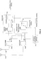
- FIG. 2 is a simplified functional block diagram of an exemplary base station 104 supporting a power control loop.
- the base station 104 includes two receive antennas 112 a and 112 b coupled to a receiver 202.
- the receiver 202 includes various high frequency and signal processing components, however, only those components pertinent to the inventive concepts described throughout this disclosure will be discussed.
- An analog front end 204 may be used to amplify, filter and downconvert the signals received by the antennas 112 a and 112 b to baseband signals.
- the baseband signals from the antennas 112 a and 112 b may be separately demodulated and then combined with a rake receiver (not shown) in a demodulator 206.
- a decoder 208 may be used to de-interleave and decode the combined signal from the demodulator 206.
- the demodulator 206 may also be used to generate a received signal strength indicator (RSSI) for the reverse link transmission from the combined signal.
- RSSI may be provided to a power control module 210 where it may be compared to a power set point to produce a power control signal.
- the power control signal may be used as a feedback signal by the subscriber station to increase the reverse link transmission power if the RSSI is less than the power set point, and decrease the reverse link power if the RSSI is more than the power set point. Because the power set point is typically determined from the FER of the decoded signal, it has a direct correlation to the reverse link signal quality. Accordingly, the power control signal is a good choice for controlling the switching of the antennas at the subscriber station during reverse link signal transmissions.
- the power set point is a threshold value against which the measured signal strength, specifically RSSI in the present embodiment, is compared.
- Alternate embodiments may use alternate measures of signal strength or signal quality and employ an alternate threshold metric.
- multiple thresholds are used to determine increases and/or decreases in transmit power on the reverse link. For example, the use of one threshold to determine decreases in transmit power and the use of a different lower threshold to determine increases in transmit power.
- Another example may incorporate multiple ranges, wherein the ranges are associated with control information regarding the transmit power adjustment. In this way, if the measured RSSI is within a given range, such range indicates an increase in transmit power by a predetermined amount. Other ranges may indicate other adjustment amounts.
- the control values of each range may be dynamically adjusted based on the current values of another range. Historical information may determine changes in the control values, such as changes in the threshold values and/or ranges, as well as changes in the associated control decisions.
- the power control signal may be provided to a transmitter 212.
- the transmitter 212 includes various high frequency and signal processing components, however, only those components pertinent to the inventive concepts described throughout this disclosure will be discussed.
- a puncture element 214 in the transmitter 212 may be used to puncture the power control signal from the power control module 210 into a traffic channel or overhead channel.
- the traffic or overhead channel from the puncture element 214 may then be provided to a modulator 216 before being upconverted to a carrier frequency, filtered and amplified by an analog front end 218 for transmission on the forward link via the transmit antenna 110.
- FIG. 3 is a simplified functional block diagram of an exemplary subscriber station 108 with switched transmit antenna diversity.
- the base station 104 uses two receive antennas 112a, 112b for reverse link reception, and therefore, achieves gain due to spatial diversity of the antennas 112a, 112b and the combining techniques utilized by the rake receiver (not shown).
- switched transmit antenna diversity at the subscriber station 108 further improvements in reverse link signal quality may be achieved.
- the subscriber station 108 includes a receiver 302 and transmitter 304 which share the same two transmit/receive antennas 114 a and 114 b .
- a separate duplexer 306 a and 306 b may be used to connect both the receiver 302 and the transmitter 304 to each transmit/receive antenna 114 a and 114 b .
- the duplexers' 306 a and 306 b prevent transmitter leakage from desensitizing or damaging the receiver 302 while at the same time ensuring weak signals received by the transmit/receive antennas 114 a and 114 b are directed to the receiver 302.
- the receiver 302 may be coupled to both of the transmit/receive antennas 114 a and 114 b , and the transmitter 304 may be switched between the transmit/receive antennas 114 a and 114 b using a microwave switch 308 or similar device.
- a high intercept point microwave switch with good linearity may be used to reduce out-of-band emissions during high power transmissions.
- Both the receiver 302 and the transmitter 304 include various high frequency and signal processing components, however, only those components pertinent to the inventive concepts described throughout this disclosure will be discussed.
- An analog front end 310 in the receiver 302 may be used to amplify, filter and downconvert the signals received by the transmit/receive antennas 114 a and 114 b to baseband signals.
- the baseband signals from the analog front end 310 may be separately demodulated and then combined with a rake receiver (not shown) in a demodulator 312.
- the power control signal may then be extracted from the combined signal and provided to an antenna selection module 314.
- the antenna selection module 314 may use the power control signal to control the switching of the transmitter 304 between the transmit/receive antennas 114a, 114b via duplexers 306 a and 306 b .
- the power control signal may also be provided to the transmitter 304 to control the reverse link transmission power.
- a modulated signal may be provided to an analog front end 316 for filtering and upconversion to a carrier frequency suitable for transmission over the reverse link.
- a power amplifier (not shown) in the analog front end 316 of transmitter 304 may be used to generate a high power transmission.
- the power control signal from the demodulator 312 of receiver 302 may be provided to the power amplifier of analog front end 316 to control the reverse link signal gain.
- the reverse link signal transmission from the power amplifier of analog front end 316 may be switched to the appropriate transmit/receive antenna through the microwave switch 308 under control of the antenna selection module 314.
- the antenna selection module 314 may be embodied in software capable of being executed on a general purpose processor, specific application processor, or in any other software execution environment.
- the software may reside in RAM memory, flash memory, ROM memory, EPROM memory, EEPROM memory, registers, a hard disk, a removable disk, a CD-ROM, or any other storage medium known in the art.
- the antenna selection module 314 may be embodied in hardware or in any combination of hardware and software.
- the antenna selection module314 may be an application specific integrated circuit (ASIC), a field programmable gate array (FPGA) or other programmable logic device, discrete gate or transistor logic, discrete hardware components, any combination thereof, or any other equivalent or nonequivalent structure designed to perform one or more of the described functions.
- ASIC application specific integrated circuit
- FPGA field programmable gate array
- the purpose of the antenna selection module 314 in at least one embodiment of the subscriber station is to select an antenna for transmission that will result in the best reverse link signal quality. Because of signal fluctuations experienced by the base station 104 as the subscriber station 108 travels through the cellular region (or sector), the antenna capable of the best reverse link signal quality will vary with time.
- the antenna selection module 314 may use feedback from the base station 104 to select the transmit/receive antenna with the best reverse link signal quality.
- the actual procedure used to select the transmit/receive antenna may vary depending on a variety of factors such as cost and performance tradeoffs as well as other design constraints.
- the power control signal may be used to gain insight into the reverse link signal quality.
- the antenna selection module 314 may switch the transmitter 304 to the other antenna 114a, 114b and monitor whether a decrease in power is requested by the base station 104 through the power control signal. A request for less power indicates that the reverse link signal quality from this selected antenna is better. This procedure may be continued for the duration of the call.
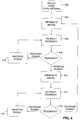
- FIG. 4 is a flow chart illustrating in more detail this exemplary procedure implemented by the antenna selection module for switching the transmitter 304 between the two antennas 114a, 114b.
- a first transmit antenna is selected in step 402.
- the initial selection of the first transmit antenna may be random, or may based on some other criteria.
- a signal is generated in step 404 that may be used to connect the transmitter to the first transmit antenna.
- the subscriber station 108 is ready to transmit.
- the antenna selection module 314 extracts feedback from the base station 104 relating to the reverse link transmission. The feedback in this case is the power control signal.
- the antenna selection module 314 determines in step 408 that the power control signal is requesting a decrease in the reverse link power, then the signal used to connect the transmitter 304 to the first transmit antenna is maintained in step 410, and the antenna selection module 314 extracts the next power control signal in step 406.
- the antenna selection module 314 determines that the power control signal is requesting an increase in the reverse link power, then the antenna selection module 314 generates a signal in step 412 to connect the transmitter to a second transmit/receive antenna. Once the transmitter is connected to the second transmit/receive antenna, the subscriber station is ready to transmit. In step 414, the antenna selection module 314 extracts the next power control signal relating to the reverse link transmission. If the antenna selection module 314 determines in step 416 that the power control signal is requesting a decrease in the reverse link power, then the signal used to connect the transmitter to the second transmit antenna is maintained in step 418, and the antenna selection module 314 extracts the next power control signal in step 414. Conversely, if the antenna selection module 314 determines in step 416 that the power control signal is requesting an increase in the reverse link transmission power, then the antenna selection module 314 generates a signal in step 404 to connect the transmitter 304 to the first transmit antenna.
- DSP digital signal processor
- ASIC application specific integrated circuit
- FPGA field programmable gate array
- a general-purpose processor may be a microprocessor, but in the alternative, the processor may be any conventional processor, controller, microcontroller, or state machine.
- a processor may also be implemented as a combination of computing devices, e.g., a combination of a DSP and a microprocessor, a plurality of microprocessors, one or more microprocessors in conjunction with a DSP core, or any other such configuration.
- a software module may reside in RAM memory, flash memory, ROM memory, EPROM memory, EEPROM memory, registers, hard disk, a removable disk, a CD-ROM, or any other form of storage medium known in the art.
- An exemplary storage medium is coupled to the processor such the processor may read information from, and write information to, the storage medium.
- the storage medium may be integral to the processor.
- the processor and the storage medium may reside in an ASIC.
- the ASIC may reside in a user terminal.
- the processor and the storage medium may reside as discrete components in a user terminal.
Description
- The present invention relates generally to communications, and more specifically, to communication devices with switched antenna transmit diversity.
- In wireless communications, transmitted signals are reflected and scattered by obstacles in their path, often resulting in multpiple copies of the signal arriving at the receiver at different times. Depending on the location of the receiving antenna relative to the transmitting antenna, and the obstacles in the signal path, the multiple copies of the signal may combine constructively or destructively at the receiving antenna. In narrow band mobile applications, this phenomenon may cause fluctuations in the signal when the user travels even a small distance. This is often referred to as fast fading. The use of a wide band code division multiple access (CDMA) signal may significantly reduce the impact of fast fading. CDMA is a modulation and multiple access scheme based on spread-spectrum communications which is well known in the art.
- Another technique to mitigate fast fading in mobile applications is to use multiple antennas to increase the gain of the signal due to spatial diversity of the antennas. Currently, there are a number of commercially available mobile devices with dual antenna arrangements. However, these mobile devices employ spatial diversity combining techniques for the received signal only, using a single antenna to transmit. In these mobile devices, it would be advantageous to employ a methodology that uses both antennas to achieve transmit antenna diversity.
- Document
US 2001/024964 A1 discloses a base transceiver station that makes a decision to change transmission diversity in response to the power control message sent by the mobile station. Such decision is made, for instance, on the basis of the result obtained from filtering the power control requests. The filtering can be carried out using a sliding window that contains power control information on the basis of which the decision is made. - In one aspect of the present invention, a method of communications includes transmitting a signal through a first antenna, receiving feedback related to the signal transmission, selecting between the first antenna and a second antenna as a function of the feedback, and transmitting the signal through the selected antenna.
- In another aspect of the present invention, a communications apparatus configured to transmit a signal to a remote source includes first and second antennas, an antenna selection module responsive to feedback from the remote source, the feedback being related to the signal transmission, and a transmitter selectively coupled between the first and second antennas under control of the antenna selection module.
- In yet another aspect of the present invention, computer readable media embodying a program of instructions executable by a computer program performs a method of transmitting a signal to a remote source, the method including receiving feedback relating to the signal transmission, selecting between the first antenna and a second antenna as a function of the feedback, and generating a signal to couple a transmitter to the selected antenna.
- In a further aspect of the present invention, a communications apparatus configured to transmit a signal to a remote source includes first and second antennas, means for selecting between the first and second antennas as a function of feedback received from the remote source, the feedback being related to the signal transmission, a transmitter, and means for coupling the transmitter to the selected antenna.
- Aspects of the present invention are illustrated by way of example, and not by way of limitation, in the accompanying drawings wherein:
-
FIG. 1 is a conceptual block diagram of an exemplary CDMA communications system; -
FIG. 2 is a simplified functional block diagram of an exemplary base station supporting a power control loop; -
FIG. 3 is a simplified functional block diagram of an exemplary subscriber station with switched transmit antenna diversity; and -
FIG. 4 is a flow chart illustrating an exemplary procedure implemented by an antenna selection module for switching a transmitter between two antennas. - The detailed description set forth below in connection with the appended drawings is intended as a description of exemplary embodiments of the present invention and is not intended to represent the only embodiments in which the present invention may be practiced. The term "exemplary" used throughout this description means "serving as an example, instance, or illustration," and should not necessarily be construed as preferred or advantageous over other embodiments. The detailed description includes specific details for the purpose of providing a thorough understanding of the present invention. However, it will be apparent to those skilled in the art that the present invention may be practiced without these specific details. In some instances, well-known structures and devices are shown in block diagram form in order to avoid obscuring the concepts of the present invention.
- In the following detailed description, various techniques will be described in the context of a CDMA communications system. While these techniques may be well suited for use in this environment, those skilled in the art will readily appreciate that these techniques are likewise applicable to other wireless networks. Accordingly, any reference to a CDMA communications system is intended only to illustrate various inventive aspects of the present invention, with the understanding that these inventive aspects have a wide range of applications.
-
FIG. 1 is a conceptual block diagram of an exemplary CDMA communications system. Abase station controller 102 may be used to provide an interface between anetwork 106 and all base stations dispersed throughout a geographic region, such as Base Station (BS) 104. The geographic region is generally divided into smaller regions known as cells. Each cell typically includes a base station capable of serving all subscriber stations in that cell. In more densely populated regions, the cell may be divided into sectors with a base station serving each sector. For ease of explanation, only onebase station 104 is shown. Asubscriber station 108 may access thenetwork 106, or communicate with other subscriber stations, through one or more base stations under control of thebase station controller 102. - The
base station 104 may be equipped with any number of antennas depending on the particular application and overall design constraints. In the CDMA communications system shown inFIG. 1 , thebase station 104 includes atransmit antenna 110 and two receive antennas 112a and 112b. The two receive antennas 112a and 112b may be used by thebase station 104 to receive a signal transmission from thesubscriber station 108. This approach increases the gain of the signal transmission due to the spatial diversity of the receive antennas 112a and 112b and the combining techniques employed by thebase station 104. The transmit and receiveantennas 110, 112a, 112b may be spatially separated individual radiating elements such as dipoles, open-ended waveguides, slots cut in waveguides, or any other type of radiating elements. - The
subscriber station 108 is shown with a dual antenna arrangement; however, as those skilled in the art will appreciate thesubscriber station 108 may be configured with any number of antennas. The two antennas 114a and 114b may be embedded in thesubscriber station 108. This approach enhances the aesthetics of the subscriber station as well as provides increased user convenience by eliminating the need to deploy the antennas during use. Alternatively, the two antennas 114a and 114b may be whips, helices, or any other type of radiating elements. - In the exemplary embodiment shown in
FIG. 1 , the two antennas 114a and 114b may be used to provide spatial diversity for the received signal on the forward link transmission. The forward link refers to a signal transmission from thebase station 104 to thesubscriber station 108. The two antennas 114a and 114b may also be used to support switched transmit diversity on the reverse link. The reverse link refers to a signal transmission from thesubscriber station 108 to thebase station 104. Switched diversity may be affected by optimally switching the reverse link signal transmission between the two antennas 114a and 114b in accordance with a control procedure. - The control procedure may be implemented in various ways depending on the particular application, overall design constraints, and/or other relevant factors. In at least one embodiment of the subscriber station, feedback from the
base station 104 may be used to optimally switch the signal transmission between the two antennas 114a and 114b. The feedback may take on various forms, but should generally provide some indication of the reverse link signal quality. The feedback is a power control signal computed at the base station and fed back to the subscriber station over an air traffic or overhead channel. Examples of reverse link quality metrics include the bit energy-to-noise density (Eb /Io), the bit error rate (BER), the frame error rate (FER), the carrier-to-interference ratio (C/I), or any other known parameter. Alternatively, the subscriber station may utilize existing feedback loops in conventional CDMA communication systems. By way of example, a power control loop used by conventional subscriber stations to control the power of the reverse link transmission may be used to control the switching of the antennas. -
FIG. 2 is a simplified functional block diagram of anexemplary base station 104 supporting a power control loop. Thebase station 104 includes two receive antennas 112a and 112b coupled to areceiver 202. Thereceiver 202 includes various high frequency and signal processing components, however, only those components pertinent to the inventive concepts described throughout this disclosure will be discussed. An analogfront end 204 may be used to amplify, filter and downconvert the signals received by the antennas 112a and 112b to baseband signals. The baseband signals from the antennas 112a and 112b may be separately demodulated and then combined with a rake receiver (not shown) in ademodulator 206. Adecoder 208 may be used to de-interleave and decode the combined signal from thedemodulator 206. - The
demodulator 206 may also be used to generate a received signal strength indicator (RSSI) for the reverse link transmission from the combined signal. The RSSI may be provided to apower control module 210 where it may be compared to a power set point to produce a power control signal. The power control signal may be used as a feedback signal by the subscriber station to increase the reverse link transmission power if the RSSI is less than the power set point, and decrease the reverse link power if the RSSI is more than the power set point. Because the power set point is typically determined from the FER of the decoded signal, it has a direct correlation to the reverse link signal quality. Accordingly, the power control signal is a good choice for controlling the switching of the antennas at the subscriber station during reverse link signal transmissions. - The power set point is a threshold value against which the measured signal strength, specifically RSSI in the present embodiment, is compared. Alternate embodiments may use alternate measures of signal strength or signal quality and employ an alternate threshold metric. In one embodiment, multiple thresholds are used to determine increases and/or decreases in transmit power on the reverse link. For example, the use of one threshold to determine decreases in transmit power and the use of a different lower threshold to determine increases in transmit power. Another example may incorporate multiple ranges, wherein the ranges are associated with control information regarding the transmit power adjustment. In this way, if the measured RSSI is within a given range, such range indicates an increase in transmit power by a predetermined amount. Other ranges may indicate other adjustment amounts. Similarly, the control values of each range may be dynamically adjusted based on the current values of another range. Historical information may determine changes in the control values, such as changes in the threshold values and/or ranges, as well as changes in the associated control decisions.
- The power control signal may be provided to a
transmitter 212. Thetransmitter 212 includes various high frequency and signal processing components, however, only those components pertinent to the inventive concepts described throughout this disclosure will be discussed. Apuncture element 214 in thetransmitter 212 may be used to puncture the power control signal from thepower control module 210 into a traffic channel or overhead channel. The traffic or overhead channel from thepuncture element 214 may then be provided to amodulator 216 before being upconverted to a carrier frequency, filtered and amplified by an analogfront end 218 for transmission on the forward link via the transmitantenna 110. -
FIG. 3 is a simplified functional block diagram of anexemplary subscriber station 108 with switched transmit antenna diversity. As explained earlier, thebase station 104 uses two receive antennas 112a, 112b for reverse link reception, and therefore, achieves gain due to spatial diversity of the antennas 112a, 112b and the combining techniques utilized by the rake receiver (not shown). By employing switched transmit antenna diversity at thesubscriber station 108 further improvements in reverse link signal quality may be achieved. - The
subscriber station 108 includes areceiver 302 andtransmitter 304 which share the same two transmit/receive antennas 114a and 114b. A separate duplexer 306a and 306b may be used to connect both thereceiver 302 and thetransmitter 304 to each transmit/receive antenna 114a and 114b. The duplexers' 306a and 306b prevent transmitter leakage from desensitizing or damaging thereceiver 302 while at the same time ensuring weak signals received by the transmit/receive antennas 114a and 114b are directed to thereceiver 302. Thereceiver 302 may be coupled to both of the transmit/receive antennas 114a and 114b, and thetransmitter 304 may be switched between the transmit/receive antennas 114a and 114b using amicrowave switch 308 or similar device. A high intercept point microwave switch with good linearity may be used to reduce out-of-band emissions during high power transmissions. Both thereceiver 302 and thetransmitter 304 include various high frequency and signal processing components, however, only those components pertinent to the inventive concepts described throughout this disclosure will be discussed. - An analog
front end 310 in thereceiver 302 may be used to amplify, filter and downconvert the signals received by the transmit/receive antennas 114a and 114b to baseband signals. The baseband signals from the analogfront end 310 may be separately demodulated and then combined with a rake receiver (not shown) in ademodulator 312. The power control signal may then be extracted from the combined signal and provided to anantenna selection module 314. In a manner to be described in greater detail later, theantenna selection module 314 may use the power control signal to control the switching of thetransmitter 304 between the transmit/receive antennas 114a, 114b via duplexers 306a and 306b. - The power control signal may also be provided to the
transmitter 304 to control the reverse link transmission power. In the exemplary embodiment shown inFIG. 3 , a modulated signal may be provided to an analogfront end 316 for filtering and upconversion to a carrier frequency suitable for transmission over the reverse link. A power amplifier (not shown) in the analogfront end 316 oftransmitter 304 may be used to generate a high power transmission. The power control signal from thedemodulator 312 ofreceiver 302 may be provided to the power amplifier of analogfront end 316 to control the reverse link signal gain. The reverse link signal transmission from the power amplifier of analogfront end 316 may be switched to the appropriate transmit/receive antenna through themicrowave switch 308 under control of theantenna selection module 314. - The
antenna selection module 314 may be embodied in software capable of being executed on a general purpose processor, specific application processor, or in any other software execution environment. The software may reside in RAM memory, flash memory, ROM memory, EPROM memory, EEPROM memory, registers, a hard disk, a removable disk, a CD-ROM, or any other storage medium known in the art. Alternatively, theantenna selection module 314 may be embodied in hardware or in any combination of hardware and software. By way of example, the antenna selection module314 may be an application specific integrated circuit (ASIC), a field programmable gate array (FPGA) or other programmable logic device, discrete gate or transistor logic, discrete hardware components, any combination thereof, or any other equivalent or nonequivalent structure designed to perform one or more of the described functions. - The purpose of the
antenna selection module 314 in at least one embodiment of the subscriber station is to select an antenna for transmission that will result in the best reverse link signal quality. Because of signal fluctuations experienced by thebase station 104 as thesubscriber station 108 travels through the cellular region (or sector), the antenna capable of the best reverse link signal quality will vary with time. Theantenna selection module 314 may use feedback from thebase station 104 to select the transmit/receive antenna with the best reverse link signal quality. The actual procedure used to select the transmit/receive antenna may vary depending on a variety of factors such as cost and performance tradeoffs as well as other design constraints. In at least one embodiment of theantenna selection module 314, the power control signal may be used to gain insight into the reverse link signal quality. More specifically, if the power control signal indicates that thebase station 104 is requesting more power, theantenna selection module 314 may switch thetransmitter 304 to the other antenna 114a, 114b and monitor whether a decrease in power is requested by thebase station 104 through the power control signal. A request for less power indicates that the reverse link signal quality from this selected antenna is better. This procedure may be continued for the duration of the call. -
FIG. 4 is a flow chart illustrating in more detail this exemplary procedure implemented by the antenna selection module for switching thetransmitter 304 between the two antennas 114a, 114b. Initially, a first transmit antenna is selected instep 402. The initial selection of the first transmit antenna may be random, or may based on some other criteria. Next, a signal is generated instep 404 that may be used to connect the transmitter to the first transmit antenna. At this point, thesubscriber station 108 is ready to transmit. Instep 406, theantenna selection module 314 extracts feedback from thebase station 104 relating to the reverse link transmission. The feedback in this case is the power control signal. If theantenna selection module 314 determines instep 408 that the power control signal is requesting a decrease in the reverse link power, then the signal used to connect thetransmitter 304 to the first transmit antenna is maintained instep 410, and theantenna selection module 314 extracts the next power control signal instep 406. - Returning to step 408, if the antenna selection module determines that the power control signal is requesting an increase in the reverse link power, then the
antenna selection module 314 generates a signal instep 412 to connect the transmitter to a second transmit/receive antenna. Once the transmitter is connected to the second transmit/receive antenna, the subscriber station is ready to transmit. Instep 414, theantenna selection module 314 extracts the next power control signal relating to the reverse link transmission. If theantenna selection module 314 determines instep 416 that the power control signal is requesting a decrease in the reverse link power, then the signal used to connect the transmitter to the second transmit antenna is maintained instep 418, and theantenna selection module 314 extracts the next power control signal instep 414. Conversely, if theantenna selection module 314 determines instep 416 that the power control signal is requesting an increase in the reverse link transmission power, then theantenna selection module 314 generates a signal instep 404 to connect thetransmitter 304 to the first transmit antenna. - The various illustrative logical blocks, modules, and circuits described in connection with the embodiments disclosed herein may be implemented or performed with a general purpose processor, a digital signal processor (DSP), an application specific integrated circuit (ASIC), a field programmable gate array (FPGA) or other programmable logic device, discrete gate or transistor logic, discrete hardware components, or any combination thereof designed to perform the functions described herein. A general-purpose processor may be a microprocessor, but in the alternative, the processor may be any conventional processor, controller, microcontroller, or state machine. A processor may also be implemented as a combination of computing devices, e.g., a combination of a DSP and a microprocessor, a plurality of microprocessors, one or more microprocessors in conjunction with a DSP core, or any other such configuration.
- The methods or algorithms described in connection with the embodiments disclosed herein may be embodied directly in hardware, in a software module executed by a processor, or in a combination of the two. A software module may reside in RAM memory, flash memory, ROM memory, EPROM memory, EEPROM memory, registers, hard disk, a removable disk, a CD-ROM, or any other form of storage medium known in the art. An exemplary storage medium is coupled to the processor such the processor may read information from, and write information to, the storage medium. In the alternative, the storage medium may be integral to the processor. The processor and the storage medium may reside in an ASIC. The ASIC may reside in a user terminal. In the alternative, the processor and the storage medium may reside as discrete components in a user terminal.
Claims (19)
- A method of communications in a system comprising base stations (104) and subscriber stations (108), comprising:transmitting a signal through a first antenna (114A) of a subscriber station;receiving feedback related to the signal transmission from a base station (104), wherein the feedback is a power control signal;selecting between the first antenna (114A) and a second antenna (114B) of the subscriber station as a function of the power control signal, wherein the, first or second, antenna is switched if the power control signal comprises a request to increase transmission power;transmitting the signal through the selected antenna; andmonitoring whether a subsequent decrease in power is requested.
- The method of claim 1, wherein the power control signal comprises a request to increase signal transmission power if the quality of the signal transmission through the first antenna is below a first threshold, and a request to decrease signal transmission power if the quality of the signal transmission through the first antenna is above a second threshold.
- The method of claim 2, wherein the first threshold equals the second threshold.
- The method of claim 2, wherein the first antenna is selected if the power control signal comprises the request to decrease the signal transmission power.
- The method of claim 2, wherein the second antenna is selected if the power control signal comprises the request to increase the signal transmission power.
- The method of claim 1, wherein the first antenna is selected by coupling a transmitter to the first antenna through a first switch and decoupling the transmitter from the second antenna with a second switch, and wherein the second antenna is selected by decoupling the transmitter from the first antenna with the first switch and coupling the transmitter to the second antenna through the second switch.
- The method of claim 1, further comprising receiving a signal through the first and second antennas.
- The method of claim 7, wherein the received signal comprises the feedback.
- The method of claim 1, wherein the power control signal comprises a request to increase signal transmission power if the quality of the signal transmission through the first antenna is within a first range, and a request to decrease signal transmission power if the quality of the signal transmission through the first antenna is within a second range.
- The method of claim 1, wherein a puncture element (214) may be used to puncture the power control signal into a traffic channel or overhead channel.
- A subscriber station, comprising:first (114A) and second (114B) antennas;means for receiving feedback related to the signal transmission from a base station, wherein the feedback is a power control signal;means for selecting between the first and second antennas as a function of the power control signal, wherein the, first or second, antenna is switched if the power control signal comprises a request to increase transmission power;a transmitter; andmeans for coupling the transmitter to the selected antenna;wherein the means for selecting is configured for monitoring whether a subsequent decrease in power is requested.
- The subscriber station of claim 11, wherein the power control signal comprises a request to increase signal transmission power if the quality of the signal transmission through the first antenna (114A) is below a first threshold, and a request to decrease signal transmission power if the quality of the signal transmission through the first antenna is above a second threshold.
- The subscriber station of claim 12, wherein the means for selecting is configured to maintain the coupling between the transmitter and the first antenna if the power control signal comprises the request to decrease the signal transmission power.
- The subscriber station of claim 12, wherein the means for selecting is configured to switch from the first antenna to the second antenna if the power control signal comprises the request to increase the signal transmission power.
- The subscriber station of claim 11, wherein the means for coupling the transmitter to the selected antenna comprises a first switch between the transmitter and the first antenna, and a second switch between the transmitter and the second antenna.
- The subscriber station of claim 11, wherein the transmitter comprises a gain responsive to the power control signal.
- The subscriber station of claim 12, wherein the first threshold equals the second threshold.
- The subscriber station of claim 11, wherein the power control signal comprises a request to increase signal transmission power if the quality of the signal transmission through the first antenna is within a first range, and a request to decrease signal transmission power if the quality of the signal transmission through the first antenna (114A) is within a second range.
- A computer program comprising instructions that when executed in a computer perform any of the methods of claims 1 to 10.
Applications Claiming Priority (3)
| Application Number | Priority Date | Filing Date | Title |
|---|---|---|---|
| US10/317,295 US7062232B2 (en) | 2002-12-11 | 2002-12-11 | Switched antenna transmit diversity |
| US317295 | 2002-12-11 | ||
| PCT/US2003/039498 WO2004054131A1 (en) | 2002-12-11 | 2003-12-10 | Switched antenna transmit diversity |
Publications (2)
| Publication Number | Publication Date |
|---|---|
| EP1576743A1 EP1576743A1 (en) | 2005-09-21 |
| EP1576743B1 true EP1576743B1 (en) | 2017-08-02 |
Family
ID=32506082
Family Applications (1)
| Application Number | Title | Priority Date | Filing Date |
|---|---|---|---|
| EP03796972.2A Expired - Lifetime EP1576743B1 (en) | 2002-12-11 | 2003-12-10 | Switched antenna transmit diversity |
Country Status (13)
| Country | Link |
|---|---|
| US (1) | US7062232B2 (en) |
| EP (1) | EP1576743B1 (en) |
| JP (1) | JP2006510262A (en) |
| KR (2) | KR101009143B1 (en) |
| CN (2) | CN1742446A (en) |
| AU (1) | AU2003297902A1 (en) |
| BR (1) | BR0317160A (en) |
| CA (1) | CA2509093C (en) |
| ES (1) | ES2644031T3 (en) |
| HU (1) | HUE034728T2 (en) |
| MX (1) | MXPA05006238A (en) |
| TW (1) | TWI345392B (en) |
| WO (1) | WO2004054131A1 (en) |
Families Citing this family (25)
| Publication number | Priority date | Publication date | Assignee | Title |
|---|---|---|---|---|
| US7542733B1 (en) * | 2003-02-04 | 2009-06-02 | Sprint Spectrum L.P. | Method and apparatus for diversity transmission from a mobile station |
| US7421276B2 (en) * | 2003-04-09 | 2008-09-02 | Nortel Networks Limited | Method, apparatus and system of configuring a wireless device based on location |
| JP3970807B2 (en) * | 2003-06-18 | 2007-09-05 | 三菱電機株式会社 | Wireless communication device |
| FR2859314A1 (en) * | 2003-08-29 | 2005-03-04 | Thomson Licensing Sa | TRANSMITTER-RECEIVER WITH DIVERSITY OF ANTENNAS |
| US7515877B2 (en) * | 2004-11-04 | 2009-04-07 | Magnolia Broadband Inc. | Communicating signals according to a quality indicator and a time boundary indicator |
| US7660598B2 (en) * | 2004-12-21 | 2010-02-09 | Qualcomm, Incorporated | Transmit power reduction for a wireless device with multiple transmit signal paths |
| KR100809551B1 (en) | 2005-03-08 | 2008-03-04 | 재단법인서울대학교산학협력재단 | An apparatus and a method for transmission which encoding a message with spact-time turbo code using feedback bit in mobile communication system |
| JP4682684B2 (en) * | 2005-04-28 | 2011-05-11 | パナソニック株式会社 | Digital signal receiver |
| US7847740B2 (en) * | 2006-02-13 | 2010-12-07 | Kyocera Corporation | Antenna system having receiver antenna diversity and configurable transmission antenna and method of management thereof |
| KR101424527B1 (en) | 2007-04-16 | 2014-08-04 | 삼성전자주식회사 | Apparatus and method for transmitting/receiving data |
| US8654715B2 (en) * | 2008-10-24 | 2014-02-18 | Qualcomm Incorporated | Systems and methods providing mobile transmit diversity |
| US8654705B2 (en) * | 2008-10-24 | 2014-02-18 | Qualcomm Incorporated | System and method for supporting multiple reverse link data streams |
| US20100329370A1 (en) * | 2009-04-28 | 2010-12-30 | Beceem Communications Inc. | Selection of a Subset of Antennas for Transmission |
| KR101231782B1 (en) * | 2010-12-13 | 2013-02-08 | 동국대학교 산학협력단 | Method of selecting sending antennas and controlling sending power in a system for transmitting sub-frames |
| US8737506B1 (en) | 2010-12-29 | 2014-05-27 | Sprint Communications Company L.P. | Determination of transmit diversity transmission delays |
| US8437713B1 (en) | 2011-02-16 | 2013-05-07 | Sprint Communications Company L.P. | Wireless transmit diversity control by location of a wireless communication device |
| US8565686B2 (en) | 2011-06-30 | 2013-10-22 | Sprint Communications Company L.P. | Power status multipath search window sizing for wireless communications |
| US9379788B2 (en) * | 2013-02-21 | 2016-06-28 | Intel Mobile Communications GmbH | Communications terminal, and a method for selecting a transmit antenna for a transmission to a radio communications network |
| JP6277529B2 (en) * | 2013-03-21 | 2018-02-14 | パナソニックIpマネジメント株式会社 | Wireless communication apparatus and transmission power control method |
| US9100100B2 (en) * | 2013-12-31 | 2015-08-04 | Futurewei Technologies, Inc. | Wireless electronic device with switchable antenna system |
| CN104506221B (en) * | 2014-12-12 | 2018-11-09 | 福建星网锐捷网络有限公司 | Method of controlling antenna and antenna |
| KR102372072B1 (en) * | 2016-02-19 | 2022-03-17 | 삼성전자주식회사 | Method for selection of transmission Antenna and electronic device supporting the same |
| CN107333340B (en) * | 2017-07-06 | 2018-12-04 | 上海交通大学 | Multibeam antenna network-building method and device |
| KR101971682B1 (en) | 2018-10-25 | 2019-08-13 | 엘아이지넥스원 주식회사 | Method fof selecting receive antenna in wireless terminal |
| US10840995B1 (en) * | 2019-11-04 | 2020-11-17 | Qualcomm Incorporated | Diversity techniques in true wireless stereo (TWS) shadowing |
Family Cites Families (22)
| Publication number | Priority date | Publication date | Assignee | Title |
|---|---|---|---|---|
| US5812935A (en) * | 1993-04-17 | 1998-09-22 | Hughes Electronics | Cellular system employing base station transmit diversity according to transmission quality level |
| US5437055A (en) * | 1993-06-03 | 1995-07-25 | Qualcomm Incorporated | Antenna system for multipath diversity in an indoor microcellular communication system |
| US5574747A (en) * | 1995-01-04 | 1996-11-12 | Interdigital Technology Corporation | Spread spectrum adaptive power control system and method |
| JP3111906B2 (en) * | 1996-07-17 | 2000-11-27 | 日本電気株式会社 | Wireless base station device |
| CA2188845A1 (en) * | 1996-10-25 | 1998-04-25 | Stephen Ross Todd | Diversity Antenna Selection |
| US6108526A (en) * | 1997-05-07 | 2000-08-22 | Lucent Technologies, Inc. | Antenna system and method thereof |
| JP2002026796A (en) * | 1998-04-07 | 2002-01-25 | Matsushita Electric Ind Co Ltd | Wireless communication equipment and wireless communication system |
| JP3471756B2 (en) * | 1998-06-13 | 2003-12-02 | サムスン エレクトロニクス カンパニー リミテッド | Apparatus and method for measuring non-orthogonal noise in CDMA communication system |
| US6690652B1 (en) * | 1998-10-26 | 2004-02-10 | International Business Machines Corporation | Adaptive power control in wideband CDMA cellular systems (WCDMA) and methods of operation |
| US6252910B1 (en) * | 1998-11-11 | 2001-06-26 | Comspace Corporation | Bandwidth efficient QAM on a TDM-FDM system for wireless communications |
| FI982763A (en) | 1998-12-21 | 2000-06-22 | Nokia Networks Oy | Procedure for data communication and radio systems |
| US6947469B2 (en) * | 1999-05-07 | 2005-09-20 | Intel Corporation | Method and Apparatus for wireless spread spectrum communication with preamble processing period |
| FI19991940A (en) * | 1999-09-10 | 2001-03-10 | Nokia Networks Oy | transmit diversity |
| DE50001058D1 (en) * | 1999-11-30 | 2003-02-13 | Fraunhofer Ges Forschung | DECT TRANSMITTER / RECEIVER TERMINAL AND METHOD FOR COMMUNICATING BETWEEN A DECT TRANSMITTER / RECEIVER TERMINAL DEVICE AND A DECT BASE STATION |
| KR100353641B1 (en) * | 2000-12-21 | 2002-09-28 | 삼성전자 주식회사 | Base station transmit antenna diversity apparatus and method in cdma communication system |
| JP2002271266A (en) * | 2001-03-09 | 2002-09-20 | Nec Corp | Cdma base station, and transmission diversity control method |
| JP3818078B2 (en) * | 2001-03-30 | 2006-09-06 | 株式会社デンソー | Diversity radio |
| US6785341B2 (en) * | 2001-05-11 | 2004-08-31 | Qualcomm Incorporated | Method and apparatus for processing data in a multiple-input multiple-output (MIMO) communication system utilizing channel state information |
| US6662024B2 (en) | 2001-05-16 | 2003-12-09 | Qualcomm Incorporated | Method and apparatus for allocating downlink resources in a multiple-input multiple-output (MIMO) communication system |
| US7010316B2 (en) * | 2001-09-28 | 2006-03-07 | Qualcomm Incorporated | Method and apparatus for multi-channel reverse link outer-loop power control |
| US7212788B2 (en) * | 2002-08-13 | 2007-05-01 | Atheros Communications, Inc. | Method and apparatus for signal power loss reduction in RF communication systems |
| US20040087332A1 (en) * | 2002-10-31 | 2004-05-06 | Samsung Electronics Co., Ltd. | Apparatus and method for simultaneous operation of a base transceiver subsystem in a wireless network |
-
2002
- 2002-12-11 US US10/317,295 patent/US7062232B2/en not_active Expired - Lifetime
-
2003
- 2003-12-10 KR KR1020057010343A patent/KR101009143B1/en active IP Right Grant
- 2003-12-10 KR KR1020107021307A patent/KR101009215B1/en active IP Right Grant
- 2003-12-10 BR BR0317160-4A patent/BR0317160A/en not_active Application Discontinuation
- 2003-12-10 MX MXPA05006238A patent/MXPA05006238A/en active IP Right Grant
- 2003-12-10 AU AU2003297902A patent/AU2003297902A1/en not_active Abandoned
- 2003-12-10 JP JP2004558718A patent/JP2006510262A/en active Pending
- 2003-12-10 CA CA2509093A patent/CA2509093C/en not_active Expired - Lifetime
- 2003-12-10 HU HUE03796972A patent/HUE034728T2/en unknown
- 2003-12-10 CN CNA2003801053576A patent/CN1742446A/en active Pending
- 2003-12-10 CN CN2012105070054A patent/CN103051364A/en active Pending
- 2003-12-10 EP EP03796972.2A patent/EP1576743B1/en not_active Expired - Lifetime
- 2003-12-10 ES ES03796972.2T patent/ES2644031T3/en not_active Expired - Lifetime
- 2003-12-10 WO PCT/US2003/039498 patent/WO2004054131A1/en active Application Filing
- 2003-12-11 TW TW092135030A patent/TWI345392B/en not_active IP Right Cessation
Non-Patent Citations (1)
| Title |
|---|
| None * |
Also Published As
| Publication number | Publication date |
|---|---|
| KR101009215B1 (en) | 2011-01-19 |
| US7062232B2 (en) | 2006-06-13 |
| CN103051364A (en) | 2013-04-17 |
| ES2644031T3 (en) | 2017-11-27 |
| JP2006510262A (en) | 2006-03-23 |
| AU2003297902A1 (en) | 2004-06-30 |
| CA2509093A1 (en) | 2004-06-24 |
| TWI345392B (en) | 2011-07-11 |
| BR0317160A (en) | 2005-11-01 |
| US20040203541A1 (en) | 2004-10-14 |
| WO2004054131A1 (en) | 2004-06-24 |
| MXPA05006238A (en) | 2005-09-08 |
| CA2509093C (en) | 2012-10-16 |
| HUE034728T2 (en) | 2018-02-28 |
| TW200419996A (en) | 2004-10-01 |
| KR20050085433A (en) | 2005-08-29 |
| KR20100117683A (en) | 2010-11-03 |
| EP1576743A1 (en) | 2005-09-21 |
| KR101009143B1 (en) | 2011-01-18 |
| CN1742446A (en) | 2006-03-01 |
Similar Documents
| Publication | Publication Date | Title |
|---|---|---|
| EP1576743B1 (en) | Switched antenna transmit diversity | |
| US7072628B2 (en) | Method and apparatus for determining receive diversity in mobile station | |
| US7245600B2 (en) | Method and apparatus for determining reverse link load level for reverse link data scheduling in a CDMA communication system | |
| JP4425927B2 (en) | Method and apparatus for reducing the transient effects of beam switching in a switched beam antenna system | |
| US6937584B2 (en) | Method and apparatus for controlling gain level of a supplemental channel in a CDMA communication system | |
| US20040192371A1 (en) | Method and system for power control during the traffic channel initialization period in a CDMA network | |
| US6915116B2 (en) | Transmission diversity | |
| US8031622B2 (en) | Method and apparatus for receive diversity in a communication system | |
| US20060223565A1 (en) | Method to optimize forward link capacity from a mixed population of single- and dual-diversity mobile stations | |
| US8204534B2 (en) | Transmit power control system, transmit power control method, and terminal device | |
| EP1325577B1 (en) | Simplified quality indicator bit test procedures | |
| US8805295B2 (en) | System and method utilizing transmit diversity | |
| AU2001296701A1 (en) | Simplified quality indicator bit test procedures | |
| AU2006200633B2 (en) | Simplified quality indicator bit test procedures |
Legal Events
| Date | Code | Title | Description |
|---|---|---|---|
| PUAI | Public reference made under article 153(3) epc to a published international application that has entered the european phase |
Free format text: ORIGINAL CODE: 0009012 |
|
| 17P | Request for examination filed |
Effective date: 20050711 |
|
| AK | Designated contracting states |
Kind code of ref document: A1 Designated state(s): AT BE BG CH CY CZ DE DK EE ES FI FR GB GR HU IE IT LI LU MC NL PT RO SE SI SK TR |
|
| AX | Request for extension of the european patent |
Extension state: AL LT LV MK |
|
| DAX | Request for extension of the european patent (deleted) | ||
| 17Q | First examination report despatched |
Effective date: 20120222 |
|
| REG | Reference to a national code |
Ref country code: DE Ref legal event code: R079 Ref document number: 60350476 Country of ref document: DE Free format text: PREVIOUS MAIN CLASS: H04B0007060000 Ipc: H04B0007040000 |
|
| GRAP | Despatch of communication of intention to grant a patent |
Free format text: ORIGINAL CODE: EPIDOSNIGR1 |
|
| RIC1 | Information provided on ipc code assigned before grant |
Ipc: H04B 7/06 20060101ALI20160908BHEP Ipc: H04B 7/04 20060101AFI20160908BHEP |
|
| INTG | Intention to grant announced |
Effective date: 20160929 |
|
| GRAJ | Information related to disapproval of communication of intention to grant by the applicant or resumption of examination proceedings by the epo deleted |
Free format text: ORIGINAL CODE: EPIDOSDIGR1 |
|
| GRAJ | Information related to disapproval of communication of intention to grant by the applicant or resumption of examination proceedings by the epo deleted |
Free format text: ORIGINAL CODE: EPIDOSDIGR1 |
|
| GRAP | Despatch of communication of intention to grant a patent |
Free format text: ORIGINAL CODE: EPIDOSNIGR1 |
|
| GRAP | Despatch of communication of intention to grant a patent |
Free format text: ORIGINAL CODE: EPIDOSNIGR1 |
|
| INTC | Intention to grant announced (deleted) | ||
| INTG | Intention to grant announced |
Effective date: 20170215 |
|
| GRAS | Grant fee paid |
Free format text: ORIGINAL CODE: EPIDOSNIGR3 |
|
| GRAA | (expected) grant |
Free format text: ORIGINAL CODE: 0009210 |
|
| AK | Designated contracting states |
Kind code of ref document: B1 Designated state(s): AT BE BG CH CY CZ DE DK EE ES FI FR GB GR HU IE IT LI LU MC NL PT RO SE SI SK TR |
|
| REG | Reference to a national code |
Ref country code: GB Ref legal event code: FG4D |
|
| REG | Reference to a national code |
Ref country code: CH Ref legal event code: EP Ref country code: AT Ref legal event code: REF Ref document number: 915507 Country of ref document: AT Kind code of ref document: T Effective date: 20170815 |
|
| REG | Reference to a national code |
Ref country code: IE Ref legal event code: FG4D |
|
| REG | Reference to a national code |
Ref country code: DE Ref legal event code: R096 Ref document number: 60350476 Country of ref document: DE |
|
| REG | Reference to a national code |
Ref country code: NL Ref legal event code: FP |
|
| REG | Reference to a national code |
Ref country code: ES Ref legal event code: FG2A Ref document number: 2644031 Country of ref document: ES Kind code of ref document: T3 Effective date: 20171127 |
|
| REG | Reference to a national code |
Ref country code: AT Ref legal event code: MK05 Ref document number: 915507 Country of ref document: AT Kind code of ref document: T Effective date: 20170802 |
|
| REG | Reference to a national code |
Ref country code: FR Ref legal event code: PLFP Year of fee payment: 15 |
|
| PG25 | Lapsed in a contracting state [announced via postgrant information from national office to epo] |
Ref country code: SE Free format text: LAPSE BECAUSE OF FAILURE TO SUBMIT A TRANSLATION OF THE DESCRIPTION OR TO PAY THE FEE WITHIN THE PRESCRIBED TIME-LIMIT Effective date: 20170802 Ref country code: AT Free format text: LAPSE BECAUSE OF FAILURE TO SUBMIT A TRANSLATION OF THE DESCRIPTION OR TO PAY THE FEE WITHIN THE PRESCRIBED TIME-LIMIT Effective date: 20170802 |
|
| PG25 | Lapsed in a contracting state [announced via postgrant information from national office to epo] |
Ref country code: GR Free format text: LAPSE BECAUSE OF FAILURE TO SUBMIT A TRANSLATION OF THE DESCRIPTION OR TO PAY THE FEE WITHIN THE PRESCRIBED TIME-LIMIT Effective date: 20171103 Ref country code: BG Free format text: LAPSE BECAUSE OF FAILURE TO SUBMIT A TRANSLATION OF THE DESCRIPTION OR TO PAY THE FEE WITHIN THE PRESCRIBED TIME-LIMIT Effective date: 20171102 |
|
| REG | Reference to a national code |
Ref country code: HU Ref legal event code: AG4A Ref document number: E034728 Country of ref document: HU |
|
| PG25 | Lapsed in a contracting state [announced via postgrant information from national office to epo] |
Ref country code: RO Free format text: LAPSE BECAUSE OF FAILURE TO SUBMIT A TRANSLATION OF THE DESCRIPTION OR TO PAY THE FEE WITHIN THE PRESCRIBED TIME-LIMIT Effective date: 20170802 Ref country code: DK Free format text: LAPSE BECAUSE OF FAILURE TO SUBMIT A TRANSLATION OF THE DESCRIPTION OR TO PAY THE FEE WITHIN THE PRESCRIBED TIME-LIMIT Effective date: 20170802 Ref country code: CZ Free format text: LAPSE BECAUSE OF FAILURE TO SUBMIT A TRANSLATION OF THE DESCRIPTION OR TO PAY THE FEE WITHIN THE PRESCRIBED TIME-LIMIT Effective date: 20170802 |
|
| REG | Reference to a national code |
Ref country code: DE Ref legal event code: R097 Ref document number: 60350476 Country of ref document: DE |
|
| PG25 | Lapsed in a contracting state [announced via postgrant information from national office to epo] |
Ref country code: SK Free format text: LAPSE BECAUSE OF FAILURE TO SUBMIT A TRANSLATION OF THE DESCRIPTION OR TO PAY THE FEE WITHIN THE PRESCRIBED TIME-LIMIT Effective date: 20170802 Ref country code: EE Free format text: LAPSE BECAUSE OF FAILURE TO SUBMIT A TRANSLATION OF THE DESCRIPTION OR TO PAY THE FEE WITHIN THE PRESCRIBED TIME-LIMIT Effective date: 20170802 |
|
| PLBE | No opposition filed within time limit |
Free format text: ORIGINAL CODE: 0009261 |
|
| STAA | Information on the status of an ep patent application or granted ep patent |
Free format text: STATUS: NO OPPOSITION FILED WITHIN TIME LIMIT |
|
| 26N | No opposition filed |
Effective date: 20180503 |
|
| REG | Reference to a national code |
Ref country code: CH Ref legal event code: PL |
|
| PG25 | Lapsed in a contracting state [announced via postgrant information from national office to epo] |
Ref country code: SI Free format text: LAPSE BECAUSE OF FAILURE TO SUBMIT A TRANSLATION OF THE DESCRIPTION OR TO PAY THE FEE WITHIN THE PRESCRIBED TIME-LIMIT Effective date: 20170802 |
|
| REG | Reference to a national code |
Ref country code: IE Ref legal event code: MM4A |
|
| PG25 | Lapsed in a contracting state [announced via postgrant information from national office to epo] |
Ref country code: LU Free format text: LAPSE BECAUSE OF NON-PAYMENT OF DUE FEES Effective date: 20171210 |
|
| REG | Reference to a national code |
Ref country code: BE Ref legal event code: MM Effective date: 20171231 |
|
| PG25 | Lapsed in a contracting state [announced via postgrant information from national office to epo] |
Ref country code: IE Free format text: LAPSE BECAUSE OF NON-PAYMENT OF DUE FEES Effective date: 20171210 |
|
| PG25 | Lapsed in a contracting state [announced via postgrant information from national office to epo] |
Ref country code: LI Free format text: LAPSE BECAUSE OF NON-PAYMENT OF DUE FEES Effective date: 20171231 Ref country code: CH Free format text: LAPSE BECAUSE OF NON-PAYMENT OF DUE FEES Effective date: 20171231 Ref country code: BE Free format text: LAPSE BECAUSE OF NON-PAYMENT OF DUE FEES Effective date: 20171231 |
|
| PG25 | Lapsed in a contracting state [announced via postgrant information from national office to epo] |
Ref country code: MC Free format text: LAPSE BECAUSE OF FAILURE TO SUBMIT A TRANSLATION OF THE DESCRIPTION OR TO PAY THE FEE WITHIN THE PRESCRIBED TIME-LIMIT Effective date: 20170802 |
|
| PG25 | Lapsed in a contracting state [announced via postgrant information from national office to epo] |
Ref country code: CY Free format text: LAPSE BECAUSE OF NON-PAYMENT OF DUE FEES Effective date: 20170802 |
|
| PG25 | Lapsed in a contracting state [announced via postgrant information from national office to epo] |
Ref country code: TR Free format text: LAPSE BECAUSE OF FAILURE TO SUBMIT A TRANSLATION OF THE DESCRIPTION OR TO PAY THE FEE WITHIN THE PRESCRIBED TIME-LIMIT Effective date: 20170802 |
|
| PG25 | Lapsed in a contracting state [announced via postgrant information from national office to epo] |
Ref country code: PT Free format text: LAPSE BECAUSE OF FAILURE TO SUBMIT A TRANSLATION OF THE DESCRIPTION OR TO PAY THE FEE WITHIN THE PRESCRIBED TIME-LIMIT Effective date: 20170802 |
|
| PGFP | Annual fee paid to national office [announced via postgrant information from national office to epo] |
Ref country code: NL Payment date: 20211115 Year of fee payment: 19 Ref country code: GB Payment date: 20211130 Year of fee payment: 19 Ref country code: FI Payment date: 20211126 Year of fee payment: 19 Ref country code: FR Payment date: 20211117 Year of fee payment: 19 Ref country code: DE Payment date: 20211110 Year of fee payment: 19 |
|
| PGFP | Annual fee paid to national office [announced via postgrant information from national office to epo] |
Ref country code: IT Payment date: 20211216 Year of fee payment: 19 Ref country code: HU Payment date: 20211127 Year of fee payment: 19 |
|
| PGFP | Annual fee paid to national office [announced via postgrant information from national office to epo] |
Ref country code: ES Payment date: 20220106 Year of fee payment: 19 |
|
| REG | Reference to a national code |
Ref country code: DE Ref legal event code: R119 Ref document number: 60350476 Country of ref document: DE |
|
| REG | Reference to a national code |
Ref country code: NL Ref legal event code: MM Effective date: 20230101 |
|
| GBPC | Gb: european patent ceased through non-payment of renewal fee |
Effective date: 20221210 |
|
| PG25 | Lapsed in a contracting state [announced via postgrant information from national office to epo] |
Ref country code: NL Free format text: LAPSE BECAUSE OF NON-PAYMENT OF DUE FEES Effective date: 20230101 |
|
| PG25 | Lapsed in a contracting state [announced via postgrant information from national office to epo] |
Ref country code: GB Free format text: LAPSE BECAUSE OF NON-PAYMENT OF DUE FEES Effective date: 20221210 Ref country code: DE Free format text: LAPSE BECAUSE OF NON-PAYMENT OF DUE FEES Effective date: 20230701 |
|
| PG25 | Lapsed in a contracting state [announced via postgrant information from national office to epo] |
Ref country code: HU Free format text: LAPSE BECAUSE OF NON-PAYMENT OF DUE FEES Effective date: 20221211 Ref country code: FR Free format text: LAPSE BECAUSE OF NON-PAYMENT OF DUE FEES Effective date: 20221231 |
|
| REG | Reference to a national code |
Ref country code: ES Ref legal event code: FD2A Effective date: 20240126 |
|
| PG25 | Lapsed in a contracting state [announced via postgrant information from national office to epo] |
Ref country code: IT Free format text: LAPSE BECAUSE OF NON-PAYMENT OF DUE FEES Effective date: 20221210 |
|
| PG25 | Lapsed in a contracting state [announced via postgrant information from national office to epo] |
Ref country code: ES Free format text: LAPSE BECAUSE OF NON-PAYMENT OF DUE FEES Effective date: 20221211 |
|
| PG25 | Lapsed in a contracting state [announced via postgrant information from national office to epo] |
Ref country code: FI Free format text: LAPSE BECAUSE OF NON-PAYMENT OF DUE FEES Effective date: 20221210 Ref country code: ES Free format text: LAPSE BECAUSE OF NON-PAYMENT OF DUE FEES Effective date: 20221211 |