EP1576294B1 - Microvalve that is doubly closed in a normal manner - Google Patents
Microvalve that is doubly closed in a normal manner Download PDFInfo
- Publication number
- EP1576294B1 EP1576294B1 EP03711974A EP03711974A EP1576294B1 EP 1576294 B1 EP1576294 B1 EP 1576294B1 EP 03711974 A EP03711974 A EP 03711974A EP 03711974 A EP03711974 A EP 03711974A EP 1576294 B1 EP1576294 B1 EP 1576294B1
- Authority
- EP
- European Patent Office
- Prior art keywords
- microvalve
- closing element
- pressure
- valve
- accordance
- Prior art date
- Legal status (The legal status is an assumption and is not a legal conclusion. Google has not performed a legal analysis and makes no representation as to the accuracy of the status listed.)
- Expired - Fee Related
Links
Images


Classifications
-
- F—MECHANICAL ENGINEERING; LIGHTING; HEATING; WEAPONS; BLASTING
- F16—ENGINEERING ELEMENTS AND UNITS; GENERAL MEASURES FOR PRODUCING AND MAINTAINING EFFECTIVE FUNCTIONING OF MACHINES OR INSTALLATIONS; THERMAL INSULATION IN GENERAL
- F16K—VALVES; TAPS; COCKS; ACTUATING-FLOATS; DEVICES FOR VENTING OR AERATING
- F16K99/00—Subject matter not provided for in other groups of this subclass
- F16K99/0001—Microvalves
-
- F—MECHANICAL ENGINEERING; LIGHTING; HEATING; WEAPONS; BLASTING
- F04—POSITIVE - DISPLACEMENT MACHINES FOR LIQUIDS; PUMPS FOR LIQUIDS OR ELASTIC FLUIDS
- F04B—POSITIVE-DISPLACEMENT MACHINES FOR LIQUIDS; PUMPS
- F04B43/00—Machines, pumps, or pumping installations having flexible working members
- F04B43/02—Machines, pumps, or pumping installations having flexible working members having plate-like flexible members, e.g. diaphragms
- F04B43/04—Pumps having electric drive
- F04B43/043—Micropumps
-
- F—MECHANICAL ENGINEERING; LIGHTING; HEATING; WEAPONS; BLASTING
- F16—ENGINEERING ELEMENTS AND UNITS; GENERAL MEASURES FOR PRODUCING AND MAINTAINING EFFECTIVE FUNCTIONING OF MACHINES OR INSTALLATIONS; THERMAL INSULATION IN GENERAL
- F16K—VALVES; TAPS; COCKS; ACTUATING-FLOATS; DEVICES FOR VENTING OR AERATING
- F16K99/00—Subject matter not provided for in other groups of this subclass
- F16K99/0001—Microvalves
- F16K99/0003—Constructional types of microvalves; Details of the cutting-off member
- F16K99/0005—Lift valves
- F16K99/0007—Lift valves of cantilever type
-
- F—MECHANICAL ENGINEERING; LIGHTING; HEATING; WEAPONS; BLASTING
- F16—ENGINEERING ELEMENTS AND UNITS; GENERAL MEASURES FOR PRODUCING AND MAINTAINING EFFECTIVE FUNCTIONING OF MACHINES OR INSTALLATIONS; THERMAL INSULATION IN GENERAL
- F16K—VALVES; TAPS; COCKS; ACTUATING-FLOATS; DEVICES FOR VENTING OR AERATING
- F16K99/00—Subject matter not provided for in other groups of this subclass
- F16K99/0001—Microvalves
- F16K99/0003—Constructional types of microvalves; Details of the cutting-off member
- F16K99/0015—Diaphragm or membrane valves
-
- F—MECHANICAL ENGINEERING; LIGHTING; HEATING; WEAPONS; BLASTING
- F16—ENGINEERING ELEMENTS AND UNITS; GENERAL MEASURES FOR PRODUCING AND MAINTAINING EFFECTIVE FUNCTIONING OF MACHINES OR INSTALLATIONS; THERMAL INSULATION IN GENERAL
- F16K—VALVES; TAPS; COCKS; ACTUATING-FLOATS; DEVICES FOR VENTING OR AERATING
- F16K99/00—Subject matter not provided for in other groups of this subclass
- F16K99/0001—Microvalves
- F16K99/0034—Operating means specially adapted for microvalves
- F16K99/0042—Electric operating means therefor
- F16K99/0046—Electric operating means therefor using magnets
-
- F—MECHANICAL ENGINEERING; LIGHTING; HEATING; WEAPONS; BLASTING
- F16—ENGINEERING ELEMENTS AND UNITS; GENERAL MEASURES FOR PRODUCING AND MAINTAINING EFFECTIVE FUNCTIONING OF MACHINES OR INSTALLATIONS; THERMAL INSULATION IN GENERAL
- F16K—VALVES; TAPS; COCKS; ACTUATING-FLOATS; DEVICES FOR VENTING OR AERATING
- F16K99/00—Subject matter not provided for in other groups of this subclass
- F16K99/0001—Microvalves
- F16K99/0034—Operating means specially adapted for microvalves
- F16K99/0055—Operating means specially adapted for microvalves actuated by fluids
- F16K99/0057—Operating means specially adapted for microvalves actuated by fluids the fluid being the circulating fluid itself, e.g. check valves
-
- F—MECHANICAL ENGINEERING; LIGHTING; HEATING; WEAPONS; BLASTING
- F16—ENGINEERING ELEMENTS AND UNITS; GENERAL MEASURES FOR PRODUCING AND MAINTAINING EFFECTIVE FUNCTIONING OF MACHINES OR INSTALLATIONS; THERMAL INSULATION IN GENERAL
- F16K—VALVES; TAPS; COCKS; ACTUATING-FLOATS; DEVICES FOR VENTING OR AERATING
- F16K99/00—Subject matter not provided for in other groups of this subclass
- F16K2099/0073—Fabrication methods specifically adapted for microvalves
- F16K2099/0074—Fabrication methods specifically adapted for microvalves using photolithography, e.g. etching
-
- F—MECHANICAL ENGINEERING; LIGHTING; HEATING; WEAPONS; BLASTING
- F16—ENGINEERING ELEMENTS AND UNITS; GENERAL MEASURES FOR PRODUCING AND MAINTAINING EFFECTIVE FUNCTIONING OF MACHINES OR INSTALLATIONS; THERMAL INSULATION IN GENERAL
- F16K—VALVES; TAPS; COCKS; ACTUATING-FLOATS; DEVICES FOR VENTING OR AERATING
- F16K99/00—Subject matter not provided for in other groups of this subclass
- F16K2099/0082—Microvalves adapted for a particular use
- F16K2099/0094—Micropumps
Abstract
Description
Die vorliegende Erfindung bezieht sich auf ein normal geschlossenes Mikroventil und insbesondere ein solches Mikroventil, das sowohl bei einem Überdruck an einem Fluideinlass desselben als auch bei einem Fluidauslass desselben selbstsperrend wirkt. Ein solches Mikroventil kann als normal doppelt geschlossenes Mikroventil bezeichnet werden. Ein solches Mikroventil soll insbesondere für den Einsatz als Einlassventil in einer Mikropumpe geeignet sein.The present invention relates to a normally closed microvalve, and more particularly, to such a microvalve which is self-locking in both a positive pressure at a fluid inlet thereof and at a fluid outlet thereof. Such a microvalve may be referred to as a normally double-closed microvalve. Such a microvalve should be suitable in particular for use as an inlet valve in a micropump.
Aus dem Stand der Technik sind Mikropumpen mit passiven und aktiven Mikroventilen am Pumpeneinlass und Pumpenauslass bekannt.From the state of the art, micropumps with passive and active microvalves at the pump inlet and pump outlet are known.
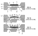
Eine bekannte Mikropumpe mit passiven Rückschlagventilen am Pumpeneinlass und Pumpenauslass ist beispielsweise aus der DE-A-19719862 bekannt und in den Fig. 1a bis 1c hierin gezeigt. Diese Pumpe umfasst einen Pumpmembranwafer 10, in dem eine Pumpmembran 12 strukturiert ist, auf der ein Piezoaktor 14 vorgesehen ist. Ferner umfasst die Pumpe einen ersten Ventilwafer 16, in dem eine Ventilklappe und ein Ventilsitz strukturiert sind. Ferner ist ein zweiter Ventilwafer 18 vorgesehen, in dem eine zweite Ventilklappe und ein zweiter Ventilsitz strukturiert sind. Bei der erfindungsgemäßen Mikromembranpumpe sind die drei Wafer gebondet, so dass ein erstes Rückschlagventil 20 zwischen einem Einlass 22 und einer Pumpkammer 24 angeordnet ist und ein zweites Rückschlagventil 26 zwischen der Pumpkammer 24 und einem Auslass 28 angeordnet ist.A known micropump with passive check valves at the pump inlet and pump outlet is known, for example, from DE-A-19719862 and shown in Figs. 1a to 1c herein. This pump comprises a
Wie in Fig. 1b gezeigt ist, zieht während eines Saughubs der Piezoaktor 14 die Membran 12 nach oben, so dass durch den sich in der Pumpkammer 24 ergebenden Unterdruck ein Fluidfluss durch das Rückschlagventil 20 vom Einlass 22 in die Pumpkammer 24 stattfindet.As shown in FIG. 1 b, during a suction stroke, the
Bei einem nachfolgenden Druckhub bewegt der Piezoaktor 14 die Membran 12 nach unten, so dass durch den in der Pumpkammer 24 entstehenden Überdruck ein Fluidfluss durch das Rückschlagventil 26 in den Auslass 28 stattfindet, wie in Fig. 1c gezeigt ist. Hinsichtlich der weiteren Einzelheiten einer solchen Mikropumpe mit passiven Rückschlagventilen wird auf die oben genannten DE-A-19719862 verwiesen.In a subsequent pressure stroke of the
Nachteilig an einer Mikropumpe mit passiven Rückschlagventilen der oben beschriebenen Art ist, dass, wenn ein Überdruck am Einlass 22 vorliegt, die Rückschlagventile 20 und 26 öffnen, so dass ein unerwünschter Fluss, ein sogenannter Free-Flow oder Freifluss, durch die Pumpe stattfinden kann.A disadvantage of a micropump with passive check valves of the type described above is that when there is an overpressure at the
Bei einer Vielzahl von Anwendungen ist jedoch ein solcher Freifluss unerwünscht bzw. sogar verboten. Derartige Anwendungen umfassen alle, deren Betriebsbedingungen einen Überdruck am Einlass möglich machen und bei denen trotzdem kein freier Fluss stattfinden soll. Anwendungen, bei denen ein solcher freier Fluss im stromlosen Zustand vermieden werden muß, existieren beispielsweise auf dem Gebiet der Medizintechnik oder von Brennstoffzellen.In a variety of applications, however, such a free flow is undesirable or even prohibited. Such applications include all those whose operating conditions make positive pressure possible at the inlet and in which, nevertheless, free flow should not take place. Applications in which such free flow in the de-energized state must be avoided exist, for example, in the field of medical technology or of fuel cells.
Ein weiterer Nachteil der in den Fig. 1a bis 1c gezeigten Mikropumpe besteht darin, dass zur Realisierung dieser Mikropumpe im Schichtaufbau mindestens drei Schichten benötigt werden, nämlich die Pumpmembranschicht 10 und die beiden Ventilschichten 16 und 18.A further disadvantage of the micropump shown in FIGS. 1 a to 1 c is that at least three layers are required for the realization of this micropump in the layer structure, namely the
Um einen solchen unerwünschten Freifluss zu verhindern, gab es im Stand der Technik eine Anzahl von Lösungsansätzen. Beispielsweise wurden Rückschlagventile entwickelt, die in die geschlossene Position vorgespannt sind, beispielsweise durch eine geeignete Beschichtung auf der Ventilklappe. Nachteilig hierbei ist, dass dazu aufwendige Prozesse erforderlich sind, wobei geeignete Beschichtungen schwierig zu realisieren sind, insbesondere mit den weiterfolgenden Anforderungen an einen dichten Waferverbindungsprozess. Derartige vorgespannte Rückschlagventile sind zwar normal geschlossen, öffnen aber bei einem Schwelldruck, d. h. wenn der Einlassdruck einen bestimmten Wert übersteigt, so dass durch derartige Rückschlagventile ein freier Fluss nicht zuverlässig ausgeschlossen werden kann.In order to prevent such unwanted free flow, there have been a number of approaches in the art. For example, check valves have been developed which are biased to the closed position, for example, by a suitable coating on the valve flap. The disadvantage here is that this requires complex processes where appropriate coatings are difficult to realize, especially with the continuing requirements for a dense wafer bonding process. Although such preloaded check valves are normally closed, but open at a threshold pressure, that is, when the inlet pressure exceeds a certain value, so that such a check valve free flow can not be reliably excluded.
Weiterhin ist es aus dem Stand der Technik bekannt, ein normal geschlossenes Mikroventil (im unbetätigten Zustand geschlossenes Mikroventil) dem Einlass einer Mikromembranpumpe mit passiven Rückschlagventilen vorzuschalten. Eine solche Lösung, wie sie hierin in Fig. 2 gezeigt ist, ist in der WO-A-02/27194 offenbart.Furthermore, it is known from the prior art to connect a normally closed microvalve (in the unactuated state closed microvalve) to the inlet of a micromembrane pump with passive check valves. Such a solution, as shown in Fig. 2 herein, is disclosed in WO-A-02/27194.
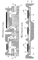
Die in Fig. 2 gezeigte Struktur umfasst eine Mikromembranpumpe 40 mit passiven Rückschlagventilen, wie sie oben Bezug nehmend auf die Fig. 1a bis 1c beschrieben ist. Ferner umfasst die dort gezeigte Struktur ein Trägersubstrat 42 mit in demselben gebildeten Fluidkanälen 44, 46 und 48. Der Fluidkanal 48 ist mit dem Auslass 28 der Mikromembranpumpe 40 fluidmäßig verbunden, während der Fluidkanal 46 mit dem Einlass 22 der Mikromembranpumpe 40 fluidmäßig verbunden ist. Die in Fig. 2 gezeigte Struktur umfasst ferner ein normal geschlossenes Mikroventil 50, dessen Auslass 52 mit dem Fluidkanal 46 und somit dem Einlass 22 der Mikromembranpumpe 40 fluidmäßig verbunden ist, und dessen Einlass 54 mit dem Fluidkanal 44 fluidmäßig verbunden ist. Die Pumprichtung ist in Fig. 2 durch Pfeile 56 gezeigt. Hinsichtlich des Aufbaus des normal geschlossenen Mikroventils 50 wird auf die Offenbarung der WO-A-02/27194 und ferner die nachfolgende Beschreibung der Fig. 4a bis 4d verwiesen.The structure shown in Fig. 2 comprises a micro diaphragm pump 40 with passive check valves as described above with reference to Figs. 1a to 1c. Further, the structure shown therein includes a
Nachteilig an der in Fig. 2 gezeigten Lösung einer Serienschaltung zwischen einer Mikropumpe 40 mit passiven Rückschlagventilen und einem normal geschlossenen Mikroventil 50 ist das erforderliche separate Bauelement, was diese Lösung teuer und aufwendig macht.A disadvantage of the solution shown in FIG. 2 of a series connection between a micropump 40 with passive check valves and a normally closed
Weiterhin sind aus dem Stand der Technik Mikroperistaltikpumpen mit integrierten aktiven, normal geöffneten Ventilen bekannt. Der Vorteil derartiger Mikroperistaltikpumpen besteht darin, dass ein aktives Schließen des Strömungspfads möglich ist. Diese Pumpen sind jedoch nachteilig dahingehend, da sie nicht stromlos sperrend sind, da die Ventile im unbetätigten Zustand offen sind. Weiterhin besitzen Peristaltikpumpen den generellen Nachteil, dass mehrere Antriebselemente benötigt werden.Furthermore, known from the prior art microperistaltic pumps with integrated active, normally open valves. The advantage of such micro-peristaltic pumps is that an active closing of the flow path is possible. However, these pumps are disadvantageous in that they are not de-energized, since the valves are open in the unactuated state. Furthermore, peristaltic pumps have the general disadvantage that multiple drive elements are needed.
Aus der oben genannten WO-A-02/27194 sind ferner Mikroperistaltikpumpen mit aktiven Ventilen am Einlass und am Auslass bekannt. Eine derartige Mikroperistaltikpumpe ist in Fig. 3 gezeigt.From the above-mentioned WO-A-02/27194 micro-peristaltic pumps with active valves at the inlet and at the outlet are also known. Such a micro-peristaltic pump is shown in FIG.
Die in Fig. 3 gezeigte Mikroperistaltikpumpe umfasst zwei gegensinnig angeordnete normal geschlossene Ventile 60a und 60b. Die Ventilklappen 62 der normal geschlossenen Ventile 60a und 60b sind in einem Ventilklappenchip 64 integriert. Aktormembrane 66 der beiden Ventile 60a und 60b sowie eine Pumpmembran 68 sind in einem Membranchip 70 integriert. Die Chips 64 und 70 sind strukturiert, um zwischen denselben eine Pumpkammer 72 zu definieren. Auf den Aktormembranen 66 und der Pumpmembran 68 sind jeweils Piezoaktoren 74, 76 und 78 vorgesehen. Die Spannungen, die an die Piezoaktoren 74, 76 und 78 angelegt werden, können geeignet gesteuert werden, um eine peristaltische Pumpwirkung von dem Einlass 80 über die Pumpkammer 72 zu dem Auslass 82 zu implementieren. Hinsichtlich weiterer Einzelheiten der in Fig. 3 gezeigten peristaltischen Mikropumpe wird wiederum auf die Offenbarung der WO-A-02/27194 verwiesen.The micro-peristaltic pump shown in Fig. 3 comprises two oppositely disposed normally closed valves 60a and 60b. The
Nachteilig an der in Fig. 3 gezeigten Mikroperistaltikpumpe ist neben dem Erfordernis mehrerer Antriebselemente, dass beim Druckhub bei großen Druckdifferenzen das Einlassventil nicht geschlossen gehalten werden kann.A disadvantage of the Mikroperistaltikpumpe shown in Fig. 3 is in addition to the requirement of multiple drive elements, that During the pressure stroke at large pressure differences, the inlet valve can not be kept closed.
Ein normal geschlossenes Mikroventil, wie es jeweils am Einlass der in den Fig. 2 und 3 gezeigten bekannten Pumpen verwendet ist, wird nachfolgend Bezug nehmend auf die Fig. 4a bis 4d näher erläutert. Ferner wird hiermit die Offenbarung der WO-A-02/27194 bezüglich des Aufbaus und der Funktionsweise eines solchen normal geschlossenen Mikroventils aufgenommen.A normally closed microvalve, as used in each case at the inlet of the known pumps shown in FIGS. 2 and 3, will be explained in more detail below with reference to FIGS. 4a to 4d. Furthermore, the disclosure of WO-A-02/27194 is hereby incorporated with respect to the structure and operation of such a normally closed microvalve.
Fig. 4a zeigt eine Untenansicht eines Aktorchips 100 des Ventils, Fig. 4b zeigt eine Schnittansicht entlang der Linie x-x in Fig. 4a im unbetätigten Zustand, Fig. 4c zeigt eine Schnittansicht entlang der Linie x-x in Fig. 4a im betätigten Zustand, und Fig. 4d zeigt eine Draufsicht auf einen Klappenchip 102 des Ventils. Es wird darauf hingewiesen, dass die Figuren hierin Strukturen exemplarisch mit Abschrägungen zeigen, wie sie beim KOH-Ätzen von Siliziumsubstraten auftreten, wobei die gezeigten Strukturen jedoch auch auf andere Weisen ohne Abschrägungen hergestellt werden können.4a shows a bottom view of an
Der Aktorchip 100 weist auf einer ersten Hauptseite 104 eine Absenkung bzw. Ausnehmung 106 auf, während auf einer gegenüberliegenden Hauptseite 108 eine Absenkung bzw. Ausnehmung 110 vorgesehen ist. Durch die beiden Absenkungen 106 und 110 ist eine Aktormembran 112 gebildet. Auf einer Seite der Aktormembran 112 ist eine Piezokeramik 114 vorgesehen, während auf der gegenüberliegenden Seite der Aktormembran 112 ein Stößel 116 vorsteht. In Fig. 4a sind der Stößel 116 die Absenkung 110 und mit gestrichelter Linie der Bereich der Absenkung, der die Aktormembran 112 bildet, gezeigt.The
Die Aktormembran 112 und der Stößel 116 sind in lateraler Richtung im wesentlichen quadratisch gebildet und zudem in einer zentrischen Anordnung angeordnet. Ferner ist in Fig. 4a zu sehen, dass die Membran 112 entlang drei ihrer vier Seiten bzw. Kantenabschnitte von einer Dichtlippe 120 umgeben ist. Wie am besten in Fig. 4b und 4c zu sehen ist, ist die Dichtlippe 120 auf der Seite 108 des Aktorchips 100 gebildet und wird vorzugsweise gleichzeitig mit dem Stößel 116 strukturiert. Der Klappenchip 102 ist mit dem Aktorchip 100 verbunden und umfasst einen Auslassbereich 130 und einen Einlasskanalbereich 140. Der Auslassbereich 130 umfasst eine Auslassöffnung 132, die den Klappenchip 102 vollständig durchdringt, während der Eingangskanalbereich 140 eine Einlassöffnung 142 umfasst, die ebenfalls den Klappenchip 102 vollständig durchdringt. Der Einlasskanalbereich 140 ist durch eine Absenkung in der zweiten Hauptseite des Klappenchips 102 gebildet, die sich bis zu einer Verschlussklappe bzw. einer Klappmembran 150 erstreckt.The
Die Verschlussklappe 150 ist, wie es in Fig. 4d gezeigt ist, in einer quadratischen Form gebildet, und ist an drei von vier ihrer Seiten bzw. Kanten über die Einlassöffnung 142 gegenüber dem Rest des Klappenchips 102 frei bewegbar, während dieselbe an der vierten Seite befestigt bzw. eingespannt ist. Die Ventilklappe 150 erstreckt sich entlang ihrer lateralen Ausdehnung etwas über die laterale Ausdehnung der Dichtlippe 120 hinaus, so dass die Einlassöffnung 142 und der Einlasskanalbereich 140 in dem normalerweise geschlossenen Zustand des Ventils seitlich durch den Klappenchip 102 und gegen den Auslassbereich 130 durch die Ventilklappe 150, die Dichtlippe 120 und einen Teil der Absenkung 110, der die Dichtlippe 120 umgibt, begrenzt ist.The
Bei dem in den Fig. 4a bis 4d gezeigten normal geschlossenen Ventil ist die Verschlussklappe 150 derart angeordnet, dass die lateralen Abmessungen der Verschlussklappe 150 größer als die umlaufende Dichtlippe 120 des Aktorchips 102 sind, und dass der Einlassdruck, der durch ein zu schaltendes Fluid in dem Einlasskanalbereich 140 auf die an den Einlasskanalbereich 140 angrenzende Verschlussklappe 150 ausgeübt wird, schließend wirkt. Ohne Anlegen einer Spannung an die Piezokeramik 114 und damit ohne Druckbeaufschlagung auf die Verschlussklappe 150 ist folglich die Verschlussklappe 150 geschlossen. Zum Öffnen des Ventils wird eine in Polarisationsrichtung positive Spannung an den Silizium-Piezo-Biegewandler, der durch die Piezokeramik 114 und die Membran 112 gebildet ist, angelegt, wodurch der Silizium-Piezo-Biegewandler mit dem Stößel 116 die Verschlussklappe 150 gegen den Einlassdruck aufdrückt, siehe Fig. 4c. Genauer gesagt wird durch die an der Piezokeramik 114 in Polarisationsrichtung anliegende, positive Spannung die Membran 112 zusammen mit dem Stößel 116 in Richtung der Ventilklappe 150 bewegt, die sich aufgrund des Drucks des Stößels 116 aufbiegt und einen Spalt 152 zwischen sich und der Dichtlippe 120 bildet.In the normally-closed valve shown in FIGS. 4a to 4d, the
Das oben Bezug nehmend auf die Fig. 4a bis 4d beschriebene, selbstsperrende, aktive Mikroventil hat die Eigenschaft, dass es beim Anlegen eines Überdrucks am Einlass 140 sperrt. Ein Referenzdruck, der von der der Ventilklappe 150 gegenüberliegenden Seite auf die Membran 112 wirkt, bei dem es sich typischerweise um den Atmosphärendruck handelt, wirkt für das Mikroventil tendenziell öffnend. Es hat sich ferner herausgestellt, dass bei dem in der WO-A-02/27194 beschriebenen Mikroventil ein Überdruck am Auslass 130 eine tendenziell öffnende Wirkung auf das Ventil hat. Wird dieses Ventil somit als alleiniges Einlassventil einer Mikropumpe verwendet, wobei der Auslass 130 mit der Pumpkammer der Mikropumpe fluidmäßig verbunden ist, kann während einer Pumpphase, während der in der Pumpkammer ein Überdruck herrscht, ein Rückfluss durch das Einlassventil auftreten.The self-locking, active microvalve described above with reference to FIGS. 4a-4d has the property of blocking at the
Die Aufgabe der vorliegenden Erfindung besteht darin, ein Mikroventil zu schaffen, das in der Lage ist, sowohl bei einem Überdruck am Auslass als auch bei einem Überdruck am Einlass selbstsperrend zu wirken.The object of the present invention is to provide a microvalve which is capable of self-locking both at an overpressure at the outlet and at an overpressure at the inlet.
Diese Aufgabe wird durch ein normal geschlossenes Mikroventil gemäß Anspruch 1 gelöst.This object is achieved by a normally closed microvalve according to
Die vorliegende Erfindung schafft ein normal geschlossenes Mikroventil mit folgenden Merkmalen:
- einem Fluideinlass;
- einem Fluidauslass;
- einem auslenkbaren Verschlusselement, das im geschlossenen Zustand des Mikroventils auf einer Dichtlippe aufliegt, so dass der Fluideinlass von dem Fluidauslass fluidmäßig getrennt ist, und das im geöffneten Zustand des Mikroventils von der Dichtlippe beabstandet ist; und
- einer auslenkbaren Haltestruktur, die mit dem Verschlusselement derart verbunden ist, dass zwischen denselben ein mit dem Fluidauslass fluidmäßig verbundener Zwischenraum existiert,
- wobei eine Krafteinwirkung auf die Haltestruktur und das Verschlusselement in einer ersten Richtung öffnend wirkt und eine Krafteinwirkung auf die Haltestruktur und das Verschlusselement in einer zweiten Richtung schließend wirkt,
- wobei der Fluideinlass und das Verschlusselement derart angeordnet sind, dass ein Druck am Fluideinlass eine Kraft in die zweite Richtung ausübt, und
- wobei eine wirksame Fläche der Haltestruktur, die bei Anlegen eines Drucks am Fluidauslass eine Kraft in der zweiten Richtung bewirkt, die größer ist als eine wirksame Fläche des Verschlusselements, die bei Anliegen eines Drucks am Fluidauslass eine Kraft in der ersten Richtung bewirkt.
- a fluid inlet;
- a fluid outlet;
- a deflectable closure element, which rests on a sealing lip in the closed state of the microvalve, so that the fluid inlet is fluidly separated from the fluid outlet, and which is spaced from the sealing lip in the open state of the microvalve; and
- a deflectable support structure connected to the closure member such that there is a gap therebetween fluidly connected to the fluid outlet,
- wherein a force acting on the support structure and the closure element acts to open in a first direction and a force acting on the support structure and the closure element acts in a second direction closing,
- wherein the fluid inlet and the closure element are arranged such that a pressure at the fluid inlet exerts a force in the second direction, and
- wherein an effective area of the support structure that, upon application of pressure to the fluid outlet, effects a force in the second direction that is greater than an effective area of the closure member that causes a force in the first direction upon application of pressure at the fluid outlet.
Die vorliegende Erfindung schafft ein normal geschlossenes Mikroventil, das in beiden Richtungen selbstsperrend ist, d. h. bei dem sowohl ein Druck am Einlass als auch ein Druck am Auslass eine Kraft auf Verschlusselement und Haltestruktur ausüben, die eine schließende Wirkung hat. Ob bei einem solchen Druck am Einlass bzw. Auslass das Mikroventil tatsächlich geschlossen bleibt, hängt, wie in der späteren detaillierten Beschreibung weiter erörtert wird, von allen drei beteiligten Drücken, d. h. dem Einlassdruck, dem Auslassdruck und dem Referenzdruck (in der Regel dem Atmosphärendruck) ab. Ein tatsächliches Schließen ist immer dann gegeben, wenn am Einlass bzw. am Auslass ein Überdruck gegenüber den anderen beiden Drücken herrscht.The present invention provides a normally closed microvalve that is self-locking in both directions, ie, in which both pressure at the inlet and pressure at the outlet exert a force on the closure member and retaining structure that has a closing effect. If at such pressure at the inlet or outlet, the microvalve will actually remain closed, as will be discussed further in the later detailed description, depending on all three pressures involved, ie inlet pressure, outlet pressure, and reference pressure (typically atmospheric pressure) , Actual closing is always given when there is overpressure at the inlet or outlet with respect to the other two pressures.
Das erfindungsgemäße normal geschlossene Mikroventil eignet sich insbesondere zur Verwendung als passives Einlassventil bei einer Mikropumpe, wobei dann der Auslass des Mikroventils mit der Pumpkammer fluidmäßig verbunden ist und der Einlass des Mikroventils den Einlass der Mikropumpe darstellt. In einem solchen Fall sperrt das Mikroventil bei Vorliegen eines Überdrucks am Einlass der Mikropumpe und ferner bei Vorliegen eines Überdrucks in der Pumpkammer, wie er während einer Pumpphase herrscht. Das passive Mikroventil öffnet beim Anlegen eines Unterdrucks an der Auslassseite, wie er im Fall eines Saughubs in der Druckkammer herrscht.The normally closed microvalve according to the invention is particularly suitable for use as a passive inlet valve in a micropump, in which case the outlet of the microvalve is fluidically connected to the pumping chamber and the inlet of the microvalve constitutes the inlet of the micropump. In such a case, the microvalve shuts off in the presence of an overpressure at the inlet of the micropump and further in the presence of an overpressure in the pumping chamber, as it prevails during a pumping phase. The passive microvalve opens upon application of a negative pressure on the outlet side, as prevails in the case of a suction stroke in the pressure chamber.
Das erfindungsgemäße passive Mikroventil geht zunächst von einem selbstsperrenden aktiven Mikroventil, wie es in der WO-A-02/27194 beschrieben ist, aus. Dieses selbstsperrende aktive Mikroventil hat die Eigenschaft, dass es beim Anlegen eines Überdrucks am Einlass sperrt, während ein Referenzdruck, der auf die von der Ventilklappe 150 beabstandete Seite der Aktormembran 112 wirkt, tendenziell öffnend wirkt. Der Referenzdruck wird in der Regel der Atmosphärendruck sein, kann jedoch auch ein anderer Druck sein, wenn entsprechende Vorsehungen getroffen sind, so dass ein vom Atmosphärendruck unterschiedlicher Druck auf die Oberseite der Aktormembran ausgeübt wird. Wie oben ausgeführt wurde, wirkt der Einlassdruck auf die Ventilklappe tendenziell schließend, während der Auslassdruck in der zwischen der Aktormembran 112 und der Ventilklappe 150 gebildeten Ventilkammer in beiden Richtungen, also öffnend und schließend wirkt. Bei dem in der WO-A-02/27194 beschriebenen selbstsperrenden Mikroventil läuft die Dichtlippe 120 dreiseitig um die Ventilklappe 160, wobei die Dichtlippe 120 im nicht beweglichen Teil des Elements 100, das die Aktormembran 112 enthält, welche Kontakt zum Referenzdruck hat, gebildet ist. Somit ist bei diesem selbstsperrenden Mikroventil die wirksame Fläche, auf die der Auslassdruck nach unten wirkt, größer als die wirksame Fläche, auf die derselbe nach oben wirkt, also in Richtung der Membran, die Kontakt zum Referenzdruck hat. Liegt daher am Auslass 130 ein Überdruck an, etwa beim Druckhub eines Pumpzyklusses, wirkt dieser Überdruck öffnend auf den Verbund aus Aktormembran 112 und Ventilklappe 150. Liegt am Auslass 130 ein Unterdruck an, wirkt dieser schließend auf das Ventil. Es wurde somit erkannt, dass das aktive selbstsperrende Ventil der WO-A-02/27194 im stromlosen Zustand genau die umgekehrten Eigenschaften zeigt als die, die erforderlich sind, um als passives Rückschlagventil für den Einlass einer Mikromembranpumpe zu dienen.The passive microvalve according to the invention is initially based on a self-locking active microvalve, as described in WO-A-02/27194. This self-locking active microvalve has the property of blocking at the inlet upon application of positive pressure, while a reference pressure acting on the side of the
Die Ursache für die Schließbewegung und Öffnungsbewegung des Mikroventils ist die Kraftbilanz auf den Membran-Klappenverbund. Bei dem erfindungsgemäßen Mikroventil ist die wirksame Fläche, auf die der Auslassdruck nach unten wirkt, kleiner als die wirksame Fläche, auf die derselbe nach oben wirkt. Somit hat ein Druck am Auslass stets eine Nettokraft in einer Schließrichtung zur Folge, so dass ein Druck am Auslass zum Schließen des Ventils führt, sofern nicht durch die beiden anderen Drücke, den Einlassdruck und den Referenzdruck, ein solches Schließen verhindert wird.The cause of the closing movement and opening movement of the microvalve is the force balance on the membrane-valve assembly. In the microvalve of the present invention, the effective area to which the outlet pressure acts downward is smaller than the effective area to which it acts upward. Thus, pressure at the outlet will always result in net force in a closing direction such that pressure at the outlet will cause the valve to close unless the other two pressures, inlet pressure and reference pressure, prevent such closure.
Vorzugsweise ist das erfindungsgemäße normal geschlossene Mikroventil als passives Mikroventil ausgebildet, bei dem kein aktives Betätigungselement für die Haltestruktur vorgesehen ist. Alternativ kann das erfindungsgemäße Mikroventil jedoch auch als ein Mikroventil mit aktiver Betätigung der Haltestruktur implementiert sein, wobei dasselbe dann immer noch die selbstsperrende Wirkung im stromlosen Zustand bei Vorliegen eines Überdrucks am Auslass aufweist.Preferably, the normally closed microvalve according to the invention is designed as a passive microvalve, in which no active actuating element is provided for the support structure. Alternatively, however, the microvalve of the invention may also be implemented as a micro-valve with active actuation of the support structure, the same then still has the self-locking effect in the de-energized state in the presence of an overpressure at the outlet.
Erfindungsgemäß ist die Haltestruktur vorzugsweise als eine versteifte oder nicht versteifte, umlaufend eingespannte Membranstruktur in einem ersten Schichtelement ausgebildet. Vorzugsweise ist das auslenkbare Verschlusselement als eine einseitig oder zweiseitig eingespannte, versteifte oder nicht versteifte Membranstruktur in einem zweiten Schichtelement ausgebildet. Die auslenkbare Haltestruktur und das auslenkbare Verschlusselement sind vorzugsweise über ein stößelartiges Verbindungsstück fest miteinander verbunden, das einen zentralen Bereich der Haltestruktur mit einem zentralen Bereich des Verschlusselements verbindet, um auftretende Drehmomentkräfte möglichst gering zu halten.According to the invention, the holding structure is preferably designed as a stiffened or non-stiffened circumferentially clamped membrane structure in a first layer element. Preferably, the deflectable closure element is designed as a one-sided or two-sided clamped, stiffened or non-stiffened membrane structure in a second layer element. The deflectable support structure and the deflectable closure element are preferably fixedly connected to each other via a plunger-like connecting piece, which connects a central region of the support structure with a central region of the closure element in order to minimize the occurrence of torque forces.
Neben dem Verschlusselement und der Haltestruktur sind ferner die übrigen Elemente des erfindungsgemäßen Mikroventils vorzugsweise ebenfalls in dem ersten und/oder zweiten Schichtelement strukturiert.In addition to the closure element and the holding structure, the remaining elements of the microvalve according to the invention are also preferably also structured in the first and / or second layer element.
Bei einem bevorzugten Ausführungsbeispiel ist das Verschlusselement eine zweiseitig eingespannte, versteifte Membranstruktur, wobei das Mikroventil einen Fluideinlass an jeder nicht eingespannten Seite des Verschlusselements aufweist. Vorzugsweise ist eine Auslassöffnung an jeder eingespannten Seite des Verschlusselements vorgesehen.In a preferred embodiment, the closure member is a bi-clamped, stiffened membrane structure, the microvalve having a fluid inlet on each unclamped side of the closure member. Preferably, an outlet opening is provided on each clamped side of the closure element.
Die vorliegende Erfindung schafft ferner eine Mikropumpe, bei der ein erfindungsgemäßes Mikroventil als Einlassventil verwendet ist. Eine derartige Mikropumpe kann ebenfalls unter Verwendung lediglich zweier strukturierter Schichten implementiert werden, wobei der Fluidauslass des Mikroventils dann durch eine entsprechende Strukturierung der beiden Schichten direkt mit der Pumpkammer der Mikropumpe verbunden ist. Das Auslassventil einer derartigen Mikropumpe kann durch ein beliebiges herkömmliches Rückschlagventil realisiert sein.The present invention further provides a micropump in which a microvalve according to the invention is used as the inlet valve. Such a micropump can likewise be implemented using only two structured layers, wherein the fluid outlet of the microvalve is then connected directly to the pumping chamber of the micropump by a corresponding structuring of the two layers. The outlet valve of such a micropump may be realized by any conventional check valve.
Eine derartige erfindungsgemäße Mikropumpe weist zahlreiche Vorteile auf. Da das Mikroventil im stromlosen Zustand in beiden Richtungen selbstsperrend wirkt, erlaubt die Mikropumpe keinen unerwünschten Freifluss durch dieselbe. Zum Aufbau einer solchen Mikropumpe sind, wie oben erwähnt, nur zwei Schichten notwendig, so dass nur ein Fügeschritt erforderlich ist. Ferner zeigt die erfindungsgemäße Mikropumpe keine großen Ventilsümpfe, so dass ein großes Kompressionsverhältnis erreichbar ist. Sämtliche Funktionen der erfindungsgemäßen Mikropumpe sind durch nur ein Aktorelement erreichbar. Somit ist die Mikropumpe stromsparend, was insbesondere für energiekritische Anwendungen, wie z. B. implantierbare Mikropumpen, bedeutsam ist.Such a micropump according to the invention has numerous advantages. Since the microvalve is self-locking in both directions when de-energized, the micropump does not allow unwanted free flow therethrough. For the construction of such a micropump, as mentioned above, only two layers are necessary, so that only one joining step is required. Furthermore, the micropump according to the invention does not show any large valve sumps, so that a high compression ratio can be achieved. All functions of the micropump according to the invention can be achieved by only one actuator element. Thus, the micropump is energy efficient, which is especially for energy critical applications such. As implantable micropumps, is significant.
Bevorzugte Ausführungsbeispiele der vorliegenden Erfindung werden nachfolgend Bezug nehmend auf die beiliegenden Zeichnungen näher erläutert. Es zeigen:
- Fig. 1a
- bis 1c schematische Querschnittansichten einer bekannten Mikromembranpumpe mit passiven Rückschlagventilen;
- Fig. 2
- eine schematische Querschnittansicht einer bekannten Mikromembranpumpe mit zusätzlichem aktivem Einlassventil;
- Fig. 3
- eine schematische Querschnittansicht einer bekannten Mikroperistaltikpumpe;
- Fig. 4a
- bis 4d schematische Ansichten zur Erläuterung eines bekannten Mikroventils;
- Fig. 5
- eine schematische Darstellung zur Erläuterung der Kräfteverhältnisse eines erfindungsgemäßen Mikroventils;
- Fig. 6
- eine Zusammenstellung der Fig. 6a bis 6f, die schematische Ansichten eines bevorzugten Ausführungsbeispiels eines erfindungsgemäßen Mikroventils zeigen;
- Fig. 7a
- und 7b schematische Querschnittansichten eines weiteren Ausführungsbeispiels eines erfindungsgemäßen Mikroventils;
- Fig. 8a
- und 8b schematische Querschnittansichten eines weiteren Ausführungsbeispiels eines erfindungsgemäßen Mikroventils;
- Fig. 9a,
- 9b, 10a, 10b, 11a und 11b schematische Querschnittansichten zur Erläuterung der Funktionsweise eines erfindungsgemäßen Mikroventils; und
- Fig. 12a
- bis 12e schematische Ansichten einer erfindungsgemäßen Mikropumpe.
- Fig. 1a
- to 1c are schematic cross-sectional views of a known micromembrane pump with passive check valves;
- Fig. 2
- a schematic cross-sectional view of a known micromembrane pump with additional active inlet valve;
- Fig. 3
- a schematic cross-sectional view of a known Mikroperistaltikpumpe;
- Fig. 4a
- to 4d are schematic views for explaining a known microvalve;
- Fig. 5
- a schematic representation for explaining the balance of power of a microvalve according to the invention;
- Fig. 6
- a compilation of Figures 6a to 6f, which show schematic views of a preferred embodiment of a microvalve according to the invention.
- Fig. 7a
- and Fig. 7b shows schematic cross-sectional views of a further embodiment of a microvalve according to the invention;
- Fig. 8a
- and Fig. 8b shows schematic cross-sectional views of a further embodiment of a microvalve according to the invention;
- 9a,
- 9b, 10a, 10b, 11a and 11b are schematic cross-sectional views for explaining the operation of a microvalve according to the invention; and
- Fig. 12a
- to 12e are schematic views of a micropump according to the invention.
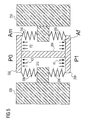
Bevor auf bevorzugte Ausführungsbeispiele der vorliegenden Erfindung näher eingegangen wird, wird zunächst auf Fig. 5 Bezug genommen, um die abhängig von einem Auslassdruck auf den Verbund aus Haltestruktur und Verschlusselement wirkenden Kräfte zu erläutern. Wie in Fig. 5 gezeigt ist, stellen bei dem erfindungsgemäßen Mikroventil und dem Ventil gemäß der WO-A-02/27194 ein Verschlusselement 200, eine Haltestruktur 202 und ein Verbindungsstück 204 eine I-Struktur dar. Diese I-Struktur ist federnd, wie in Fig. 5 durch die Federn 206 schematisch angezeigt ist, an den stationären Bereichen des Aktorchips 100 und des Klappenchips 102 (siehe Fig. 4b und 4c) angebracht, die in Fig. 5 mit den Bezugszeichen 208 und 210 versehen sind. Die federnde Lagerung ergibt sich beispielsweise durch Membranstrukturen, die jeweilige versteifte Bereiche der beweglichen Strukturen mit den stationären Bereichen verbinden. Der somit erzeugte Innenbereich 212 steht mit dem Fluidauslass in Fluidverbindung, so dass in demselben ein am Fluidauslass herrschender Druck P2 vorliegt.Before referring in detail to preferred embodiments of the present invention, reference is first made to Fig. 5 to explain the forces acting on the composite of support structure and closure element depending on an outlet pressure. As shown in FIG. 5, in the microvalve of the present invention and the valve of WO-A-02/27194, a
Auf die auslenkbare Haltestruktur 202 wirkt von der dem Innenbereich gegenüberliegenden Seite ein Referenzdruck P0, in der Regel der atmosphärische Druck. Auf das auslenkbare Verschlusselement 200 wirkt von der dem Innenbereich gegenüberliegenden Seite der Einlassdruck P1. Die auslenkbare Haltestruktur 202 besitzt eine wirksame Fläche Am, auf die der Druck P2 wirkt. Das auslenkbare Verschlusselement 200 besitzt eine wirksame Fläche Af, auf die der Druck P2 wirkt.On the
Der der vorliegenden Erfindung zugrunde liegende Lösungsgedanke besteht nun darin, den Klappen-Membranverbund, der in Fig. 5 schematisch als I-Struktur gezeigt ist, so zu gestalten, dass bei einem Überdruck am Auslass das Ventil schließt und bei einem Unterdruck am Auslass das Ventil öffnet. Darüber hinaus soll das Ventil bei einem Überdruck am Einlass selbstsperrend bleiben.The solution idea on which the present invention is based is now to design the flap membrane composite, which is shown schematically as an I structure in FIG. 5, such that the valve closes in the event of an overpressure at the outlet and the valve closes at a negative pressure at the outlet opens. In addition, the valve should remain self-locking at a positive pressure at the inlet.
Es sei angemerkt, dass bei den Betrachtungen hierin davon ausgegangen wird, dass die Bewegungsrichtung der I-Struktur (aufwärts oder abwärts) nicht durch die jeweiligen Aufhängungen der Haltestruktur und des Verschlusselements beeinflusst wird, sondern lediglich durch die Nettokraft beeinflusst wird. Unter der Annahme, dass die Flächen, auf die P1 von außen und auf die P2 von innen auf das Verschlusselement 200 wirkt, gleich sind, und dass die Flächen, auf die P0 von außen und P2 von innen auf die Haltestruktur 202 wirkt, gleich groß sind (Vernachlässigung der durch das Verbindungsstück 204 besetzten Fläche im Innenbereich), kann diese Nettokraft wie folgt berechnet werden: ![]()
![]()
Um eine selbstsperrende Wirkung zu erhalten, wird eine Nettokraft Fnet ≥ 0 benötigt. Eine solche Nettokraft wird durch das erfindungsgemäße Flächenverhältnis bewirkt.To obtain a self-locking effect, a net force F net ≥ 0 is needed. Such a net force is caused by the area ratio according to the invention.
Es wurde herausgefunden, dass die obigen Forderungen erfüllt werden können, wenn die wirksame Fläche Am der Haltestruktur 202 größer gemacht wird als die wirksame Fläche Af des Verschlusselements 200. In einem solchen Fall ist die durch den Auslassdruck P2 auf das Verschlusselement 200 ausgeübte Kraft K1 geringer als die auf die Haltestruktur 202 ausgeübte Kraft K2, so dass sich eine Nettokraft nach oben, die eine schließende Wirkung hat, ergibt.It has been found that the above requirements can be met when the effective area Am of the
Um das gewünschte Flächenverhältnis zu erreichen, sind verschiedene Möglichkeiten denkbar. Beispielsweise könnte eine einseitig eingespannte Ventilklappe an der Einspannstelle verkürzt werden, um eine geringere wirksame Fläche der Ventilklappe verglichen mit der Haltemembran zu realisieren. Dies könnte implementiert werden, indem bei dem in Fig. 4b gezeigten Mikroventil (wobei erfindungsgemäß der Piezoaktor 114 in der Regel nicht vorgesehen sein wird) den rechts an den Auslass 130 angrenzenden feststehenden Bereich des Klappenchips 102 verlängert, so dass die Länge der Ventilklappe kürzer wird. Nachteilig an dieser Lösung ist jedoch, dass dadurch eine Unsymmetrie bezüglich des Angriffspunkts des Stößels 116 und daraus resultierende Drehmomentkräfte entstehen würden.In order to achieve the desired area ratio, various possibilities are conceivable. For example, a one-sided clamped valve flap could be shortened at the clamping point in order to realize a smaller effective area of the valve flap compared to the retaining membrane. This could be implemented by extending the fixed to the right end of the
Eine bevorzugte Lösung zur Erreichung des obigen Flächenverhältnisses besteht daher darin, eine zweiseitig eingespannten Ventilklappe zu verwenden und diese an beiden eingespannten Seiten zu verkürzen.A preferred solution to achieve the above area ratio is therefore to use a two-sided clamped valve flap and to shorten these on both sides clamped.
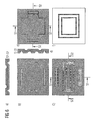
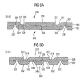
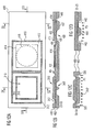
Bezug nehmend auf die Fig. 6 und 6a bis 6f wird nun ein bevorzugtes Ausführungsbeispiel eines erfindungsgemäßen Mikroventils näher erläutert. Fig. 6 zeigt dabei eine Zusammenstellung der in den Fig. 6a bis 6f gezeigten Teilansichten.With reference to FIGS. 6 and 6a to 6f, a preferred embodiment of a microvalve according to the invention will now be explained in more detail. 6 shows a compilation of the partial views shown in FIGS. 6a to 6f.
Das dargestellte Mikroventil umfasst einen zweischichtigen Aufbau mit einer Membranschicht. 300 und einer Klappenschicht 302. Die beiden Schichten 300 und 302 können beispielsweise durch beidseitig strukturierte Siliziumwafer gebildet sein, die nach dem Strukturieren derselben gebondet werden (Fusion Bond). Es ist jedoch klar, dass die beiden Schichten nicht aus Silizium bestehen müssen, sondern alternativ aus Kunststoff bestehen können und durch Heißprägen oder Spritzguss strukturiert werden können. Die Kunststoffschichten können dann mittels Kleben durch Klebstoff, mittels Anlösen mit Lösemitteln und Verkleben, mittels Laserschweißen oder mittels Ultraschallschweißen verbunden werden. Wiederum alternativ können die beiden Schichten aus Metall bestehen, durch Prägen, Stanzen, Fräsen und dergleichen strukturiert werden und nachfolgend durch Kleben oder Schweißen verbunden werden. Alternativ können Kombinationen der oben angegebenen Materialien für die Membranschicht 300 und die Klappenschicht 302 verwendet werden.The illustrated microvalve comprises a two-layered construction with a membrane layer. 300 and a
Bei den nachfolgend beschriebenen bevorzugten Ausführungsbeispielen sind die Membranschicht und die Klappenschicht jeweils aus Siliziumwafern gebildet, wobei dieselben der Einfachheit halber als Membranchip 300 und Klappenchip 302 bezeichnet werden. Ferner sind die in den Fig. gezeigten schrägen Kanten typisch für ein KOH-Ätzen in Silizium, wobei diese abgeschrägten Kanten jedoch nicht notwendig für die Erfindung sind und bei alternativen Technologien nicht auftreten.In the preferred embodiments described below, the membrane layer and the flap layer are each formed from silicon wafers, the same being referred to as
Fig. 6a zeigt eine Schnittansicht entlang der Linie S2-S2 von Fig. 6c. Fig. 6b zeigt eine Draufsicht auf den Klappenchip 302. Fig. 6c zeigt eine Untenansicht des Klappenchips 302. Fig. 6d zeigt eine Schnittansicht entlang der Linie S1-S1 in Fig. 6c. Fig. 6e zeigt eine Untenansicht des Membranchips 300, und Fig. 6f zeigt eine Draufsicht des Membranchips 300.Fig. 6a shows a sectional view taken along the line S2-S2 of Fig. 6c. Fig. 6b shows a top view of the
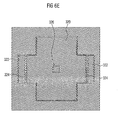
In dem Membranchip 300 ist eine auslenkbare Haltestruktur 310 in der Form einer versteiften Membranstruktur strukturiert. Dazu ist in die Oberseite des Membranchips 300 eine umlaufende Ausnehmung 312 strukturiert, wie am besten in den Fig. 6a und 6f zu sehen ist. Die umlaufende Ausnehmung 312 definiert Membranbereiche 314 und einen versteiften Bereich 316 der Membranstruktur 310. Obwohl die Membranstruktur 310 und der Versteifungsbereich 316 in Fig. 6f im wesentlichen rechteckig dargestellt sind, können diese Bereiche in alternativen Ausführungsbeispielen andere Formen aufweisen. Beispielsweise könnten die jeweiligen Ecken abgerundet sein, um dort auftretende Spannungen zu reduzieren.In the
In der Unterseite des Membranchips 300 ist eine Ventilkammerausnehmung 320 (siehe Fig. 6e), die zusammen mit der Ausnehmung 312 die Dicke der Membranbereiche 314 festlegt, strukturiert. Ferner sind in der Unterseite des Membranchips 300 Einlassbereichausnehmungen 322 strukturiert, die durch jeweilige Dichtlippen 324 von der Ventilkammerausnehmung 320 getrennt sind. Im wesentlichen zentrisch hinsichtlich des Versteifungsbereichs 316 der Membranstruktur 310 ist ein Stößel 326 in die Unterseite des Membranchips 300 strukturiert, der als Verbindungsstück zur festen Verbindung mit einem auslenkbaren Verschlusselement dient. Die Form der in der Unterseite des Membranchips 300 strukturierten Ausnehmungen hängt, wie im nachfolgenden klar wird, von der Anordnung von Einlassöffnungen und Auslassöffnungen in dem Klappenchip 302 ab, wobei die in Fig. 6e zu erkennende Form lediglich beispielhafter Natur ist.In the underside of the
In Fig. 6b, die eine Draufsicht auf den Klappenchip 302 darstellt, sind zwei Einlassöffnungen 330 und zwei Auslassöffnungen 332 zu sehen, die den Klappenchip 302 durchdringend gebildet sind. Wie am besten in Fig. 6a und Fig. 6d zu sehen ist, sind die Einlassöffnungen 330 bzw. Auslassöffnungen 332 jeweils durch ein kurzes Ätzen der Oberseite des Klappenchips 302 und durch ein längeres Ätzen von Ausnehmungen in der Unterseite des Klappenchips 302 gebildet.In Fig. 6b, which is a plan view of the
Die Einlassöffnungen 330 sind derart in dem Klappenchip 302 gebildet, dass dieselben unterhalb der Einlassbereichausnehmungen 322 in dem Membranchip angeordnet sind, wie in Fig. 6a zu sehen ist. Die Auslassöffnungen 332 sind derart in dem Klappenchip 302 vorgesehen, dass dieselben unterhalb der Ventilkammerausnehmung 320 angeordnet und mit derselben in fluidmäßiger Verbindung sind.The
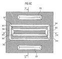
Fig. 6c zeigt eine Untenansicht des Klappenchips 302 mit den darin gebildeten Auslassöffnungen 332. Ferner ist in der Unterseite des Klappenchips 302 ein auslenkbares Verschlusselement 340 als eine versteifte Membranstruktur strukturiert. Hierzu sind zwei längliche Ausnehmungen 342 gebildet, um membranartige Trägerstrukturen 344 zu implementieren. Ferner ergibt sich dadurch ein Verstärkungsbereich 346, der durch die membranartigen Trägerstrukturen 344 an dem Klappenchip 302 zweiseitig eingespannt ist. An den jeweils kurzen Seiten des Verschlusselements 340 sind den Klappenchip 302 vollständig durchdringende Ausnehmungen 350 vorgesehen, so dass das Verschlusselement 340 an den beiden kurzen Seiten nicht eingespannt ist.6c shows a bottom view of the
Wie in Fig. 6d zu sehen ist, reichen die unbeweglichen Bereiche 352 des Klappenchips 302 auf beiden Seiten des Verschlusselements 340, das durch die Trägermembrane 344 und den Versteifungsbereich 346 gebildet ist, deutlich unter die in dem Membranchip 300 gebildete Haltestruktur 310. Dadurch ist die hinsichtlich eines Drucks in dem Zwischenraum zwischen Membranchip 300 und Klappenchip 302 wirksame Fläche des Verschlusselements 340 kleiner als die entsprechende Fläche des Membranchips 300. Somit ist bei dem in den Fig. 6a bis 6f gezeigten Mikroventil die oben angegebene Bedingung für ein in beide Richtungen selbstsperrendes Mikroventil erfüllt.As can be seen in FIG. 6 d, the
Das in den Fig. 6 bis 6f gezeigte Mikroventil ist passiv, wobei sein Öffnungszustand lediglich von den anliegenden Drücken abhängt. Der Stößel 326 ist fest mit dem Versteifungselement verbunden, wobei der Stößel bezüglich der Haltestruktur 310 und des Verschlusselements 340 vorzugsweise zentrisch angeordnet ist, um Drehmomentkräfte möglichst gering zu halten. Dagegen sind die Dichtlippen 324 nicht mit dem Verschlusselement 340 verbunden. Eine sich während der Herstellung beim Verbinden des Membranchips 300 mit dem Klappenchip 302 mögliche ergebende Verbindung zwischen Dichtlippe und Verschlusselement kann nachfolgend durch Ätzen von der Unterseite her wieder gelöst werden.The microvalve shown in FIGS. 6 to 6f is passive, its opening state being dependent only on the applied pressures. The
Dabei werden der Membranchip und der Klappenchip vorzugsweise über eine Oxidschicht gebondet, die durch Oxidieren der zu verbindenden Oberfläche des Membranchips und/oder der zu verbindenden Oberfläche des Klappenchips erzeugt wird. Eine Gesamtverbindungsschicht aus Oxid kann dann eine Dicke zwischen 100 nm und 300 nm aufweisen. In einem nachfolgenden Ätzschritt unter Verwendung von Flusssäure wird dann das Oxid unter der oder den Dichtlippen 324 entfernt, um dieselben von dem Klappenchip zu lösen. Da der Stößel 326 größere laterale Abmessungen aufweist als die Dichtlippen, wird er bei diesem Ätzschritt nicht von dem Klappenchip gelöst, sondern bleibt fest mit demselben verbunden. Sind zwischen Membranchip und Klappenchip ferner Stützelemente vorgesehen, wie später bezugnehmend auf Fig. 8b beschrieben wird, so müssen diese derart ausgebildet sein, dass sie auch bei dem obigen Ätzschritt von dem jeweiligen Fügepartner gelöst werden.In this case, the membrane chip and the flap chip are preferably bonded via an oxide layer, which is produced by oxidizing the surface of the membrane chip to be joined and / or the surface of the flap chip to be connected. An overall compound layer of oxide may then have a thickness between 100 nm and 300 nm. In a subsequent etching step using hydrofluoric acid, the oxide beneath the sealing lip (s) 324 is then removed to release it from the flapper chip. Since the
In den Fig. 6a bis 6f ist das erfindungsgemäße Mikroventil im drucklosen Zustand dargestellt. In diesem Zustand liegt das Verschlusselement 340 auf den Dichtlippen 324 auf, so dass die Fluidauslässe 332 von den Fluideinlässen 330 fluidmäßig getrennt sind.In FIGS. 6a to 6f, the microvalve according to the invention is shown in the pressureless state. In this state, the
Im Betrieb wirkt auf den Fluideinlass 330 ein Einlassdruck P1, während auf den Fluidauslass 332 ein Auslassdruck P2 wirkt. Ferner wirkt von oben auf die Haltestruktur ein Referenzdruck P0, bei dem es sich in der Regel um den atmosphärischen Druck handelt. Ferner wird, wie später Bezug nehmend auf die Fig. 8a und 8b näher erläutert wird, das Mikroventil derart auf einer mit Fluidleitungen versehenen Trägerstruktur angebracht, dass der Einlassdruck P1 von unten auf das Verschlusselement 340 wirkt. Da der Einlassdruck von unten auf das Verschlusselement 340 wirkt, wirkt das Mikroventil bei einem Überdruck am Einlass selbstsperrend. Da, wie oben erläutert wurde, die wirksame Fläche des Verschlusselements für einen Überdruck am Ventilauslass kleiner ist als die wirksame Fläche des Halteelements, bewirkt ein Überdruck am Ventilauslass eine resultierende Gesamtkraft auf den Verbund aus Verschlusselement und Haltestruktur, wobei diese resultierende Gesamtkraft schließend dahingehend wirkt, dass das Verschlusselement auf die Dichtlippe gedrückt wird, so dass die Ventilkammerausnehmung 320 von den Einlassbereichsausnehmungen 322 fluidisch getrennt sind. Somit existiert keine Fluidverbindung zwischen Fluideinlass und Fluidauslass.In operation, an inlet pressure P1 acts on the
Für den Fall eines Unterdrucks am Fluidauslass ergibt sich eine auf den Verbund aus Verschlusselement und Haltestruktur wirkende Nettokraft nach unten, so dass das Verschlusselement an beiden Enden desselben von der jeweiligen Dichtlippe 324 abhebt, so dass das Ventil im geöffneten Zustand ist. Dieses Öffnen erfolgt in analoger Weise zu dem oben Bezug nehmend auf Fig. 4c beschriebenen Öffnen des bekannten Mikroventils, mit der Ausnahme, dass erfindungsgemäß kein Betätigungselement erforderlich ist, sondern das Öffnen lediglich durch einen Unterdruck am Auslassende bewirkt werden kann.In the event of a negative pressure at the fluid outlet results in a force acting on the composite of closure element and support structure net force down, so that the closure element at both ends of the same from the
Hinsichtlich einer genaueren Betrachtungsweise unter Einschluss der beteiligten Drücke wird auf die nachfolgenden Erörterung bezüglich der Fig. 8a bis 11b verwiesen.For a more detailed view, including the pressures involved, reference is made to the following discussion with reference to FIGS. 8a to 11b.
In den Fig. 7a und 7b sind schematische Querschnittansichten eines ersten alternativen Ausführungsbeispiels eines erfindungsgemäßen Mikroventils gezeigt, die sich dadurch von dem in den Fig. 6a und 6b gezeigten Ausführungsbeispiel unterscheiden, dass die Haltestruktur durch eine nicht versteiftes Membranelement 360 gebildet ist und dass lediglich eine Auslassöffnung 332 in dem Klappenchip 302' vorgesehen ist. Um die nicht versteifte Membranstruktur zu realisieren, ist in dem Membranchip 300' eine flächige Ausnehmung 362 gebildet, die zusammen mit einer in der Unterseite des Membranchips 300' gebildeten Ventilkammerausnehmung 320 eine Membran 364 definiert, auf deren Unterseite wiederum ein Stößel 326, der mit einem Verschlusselement 340' verbunden ist, gebildet ist. Das Verschlusselement 340' ist wiederum durch entsprechende Ausnehmungen 366 in der Unterseite des Klappenchips 302' strukturiert, um vergleichbar mit dem Bezug nehmend auf die Fig. 6a bis 6f beschriebenen Ausführungsbeispiel membranartige Trägerstrukturen 368 für einen Versteifungsbereich 370 zu bilden.FIGS. 7 a and 7 b show schematic cross-sectional views of a first alternative embodiment of a microvalve according to the invention, which differ from the exemplary embodiment shown in FIGS. 6 a and 6 b in that the holding structure is formed by a
Bei dem in Fig. 7a und 7b gezeigten Ausführungsbeispiel ist der Versteifungsbereich 370 schmaler und sind die membranartigen Trägerstrukturen 368 breiter als bei dem Bezug nehmend auf die Fig. 6a bis 6f beschriebenen Ausführungsbeispiele, so dass die wirksame Fläche des Verschlusselements 340' weiter reduziert ist.In the embodiment shown in FIGS. 7a and 7b, the
Die ganzflächige Flexibilität der Haltestruktur des Bezug nehmend auf die Fig. 7a und 7b beschriebenen Ausführungsbeispiels reduziert jedoch die wirksame Fläche der Haltestruktur gegenüber einem in der Ventilkammer herrschenden Druck. Daher ist es, wie oben bereits Bezug nehmend auf die Fig. 6a bis 6f erläutert wurde, vorteilhaft, sowohl die zweiseitig eingespannte Klappe als auch die Membran der Haltestruktur in der Mitte zu versteifen, um eine optimale Kraftwirkung zu erzielen.However, the full-surface flexibility of the support structure of the reference to the embodiment described in FIGS. 7a and 7b reduces the effective area of the support structure with respect to a pressure prevailing in the valve chamber. Therefore, as already explained above with reference to FIGS. 6a to 6f, it is advantageous to stiffen both the two-sided clamped flap and the membrane of the holding structure in the middle, in order to achieve an optimal force effect.
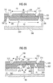
Ein Ausführungsbeispiel der vorliegenden Erfindung bei dem sowohl Klappe als auch Haltestruktur als versteifte Membran ausgebildet sind, und das nur eine Auslassöffnung aufweist, ist in den Fig. 8a und 8b gezeigt. Dieses Ausführungsbeispiel unterscheidet sich von dem in den Fig. 7a und 7b gezeigten Ausführungsbeispiel lediglich dadurch, dass die Membran der Haltestruktur versteift ist. Der Membranchip des in den Fig. 8a und 8b gezeigten Ausführungsbeispiels kann daher im wesentlichen dem des Bezug nehmend auf die Fig. 6a bis 6f beschriebenen Ausführungsbeispiels entsprechen, wobei für gleiche Elemente gleiche Bezugszeichen verwendet sind. Dagegen entspricht der Klappenchip im wesentlichen dem des in den Fig. 7a und 7b gezeigten Ausführungsbeispiels, wobei ebenfalls wiederum gleiche Bezugszeichen für gleiche Elemente verwendet sind.An embodiment of the present invention in which both the flap and the support structure are formed as a stiffened membrane, and having only one outlet opening is shown in Figs. 8a and 8b. This embodiment differs from the embodiment shown in Figs. 7a and 7b only in that the membrane of the support structure is stiffened. Therefore, the membrane chip of the embodiment shown in Figs. 8a and 8b may substantially correspond to the embodiment described with reference to Figs. 6a to 6f, wherein like reference numerals are used for like elements. In contrast, the flap chip substantially corresponds to that of the embodiment shown in FIGS. 7a and 7b, again using the same reference numerals for the same elements.
Darüber hinaus ist in den Fig. 8a und 8b eine Trägerstruktur 380 gezeigt, die einen Einlassfluidkanal 382 und einen Auslassfluidkanal 384 aufweist. Über den Einlassfluidkanal 382 liegt ein Einlassdruck P1 an den Fluideinlässen 330 an, während über den Fluidauslasskanal 384 ein Auslassdruck P2 an dem Fluidauslass 332 anliegt. Das Trägerelement 380 kann in üblicher Weise durch eine Fluidikplatte mit entsprechenden Leitungen gebildet sein.In addition, in Figs. 8a and 8b, a
Ferner sind in den Fig. 8a und 8b die zur Ermittlung der wirksamen Fläche der jeweiligen Elemente benötigten Abmessungen angegeben, wobei von einer im wesentlichen quadratischen Haltestruktur 310 mit einer Kantenlänge a und einem Verschlusselement mit einer Länge c und einer Breite b ausgegangen wird. Bei dem versteiften membranartigen Strukturen können die versteiften Regionen 316 bzw. 370 effektiv zu den wirksamen Flächen gerechnet werden, die sich wie folgt berechnen: ![]()
![]()
![]()
![]()
Dabei ist Af die wirksame Fläche des Verschlusselements und Am die wirksame Fläche der Haltestruktur.Here Af is the effective area of the closure element and Am the effective area of the support structure.
Bei den obigen Definitionen der wirksamen Flächen Af und Am wurde auf die Längen a und b zurückgegriffen. Eine genaue FEM-Analyse zeigt, dass die effektiven Längen von a und b etwas länger als in der Abbildung skizziert sind, da die wirksame Kraft zum Teil auch auf den gedünnten Aufhängungen der Haltestruktur und der Klappenstruktur wirkt.In the above definitions of the effective areas Af and Am, the lengths a and b were used. Accurate FEM analysis shows that the effective lengths of a and b are slightly longer than outlined in the figure, as the effective force acts in part on the thinned suspensions of the support structure and damper structure.
Der Einfluss der Membranbereiche auf Af und Am ist umso geringer, je flexibler die Membranbereiche sind. Der Flexibilität der Membranbereiche sind jedoch Grenzen gesetzt, da in allen Betriebszuständen des Mikroventils die Bruchspannung des Membranmaterials nicht überschritten werden darf.The influence of the membrane areas on Af and Am is the lower the more flexible the membrane areas are. The flexibility of the membrane areas, however, limits, since in all operating conditions of the microvalve, the breaking stress of the membrane material may not be exceeded.
Wie oben ausgeführt wurde, sind die erfindungsgemäßen Mikroventile derart ausgeführt, dass die wirksame Fläche Am großer als die wirksame Fläche Af ist.As stated above, the microvalves according to the invention are designed such that the effective area Am is greater than the effective area Af.
Abweichend von den obigen Ausführungsbeispielen könnte das Verschlusselement auch als Membran ohne Versteifung ausgeführt sein. Jedoch ist eine teilweise Versteifung der Klappe, d. h. des Verschlusselements, vorteilhaft dahingehend, dass Leckraten durch Verformung der Klappenränder vermieden bzw. reduziert werden.Notwithstanding the above embodiments, the closure element could also be designed as a membrane without stiffening. However, a partial stiffening of the flap, i. H. the closure element, advantageous in that leakage rates are avoided or reduced by deformation of the flap edges.
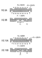
Bezug nehmend auf die Figuren 9a bis 11b wird nun das doppelt selbstsperrende Verhalten des in den Fig. 8a und 8b gezeigten Ventils beschrieben. Dabei zeigen die Fig. 9a und 9b einen Fall eines Überdrucks am Einlass. Der Referenzdruck P0 entspreche dem atmosphärischen Druck, wobei im folgenden als Näherung angenommen wird, dass der atmosphärische Druck 1000 hPa betrage. Der Einlassdruck P1 betrage 1300 hPa und der Auslassdruck entspreche ebenfalls dem atmosphärischen Druck. Somit liegt ein Überdruck am Einlass vor, der das Verschlusselement auf die Dichtlippen drückt, so dass das Ventil in dieser Situation eine selbstsperrende Funktion zeigt.Referring now to Figures 9a to 11b, the double self-locking behavior of the valve shown in Figures 8a and 8b will now be described. Here, FIGS. 9a and 9b show a case of overpressure at the inlet. The reference pressure P0 corresponds to the atmospheric pressure, and it will be assumed below that the atmospheric pressure is 1000 hPa. The inlet pressure P1 is 1300 hPa and the outlet pressure also corresponds to the atmospheric pressure. Thus, there is an overpressure at the inlet, which presses the closure element onto the sealing lips, so that the valve shows a self-locking function in this situation.
In Fig. 10a und 10b ist eine Situation gezeigt, bei der ein Überdruck am Auslass herrscht. Der Referenzdruck betrage wiederum 1000 hPa (absolut), während auch am Einlass ein Druck von 1000 hPa vorliege. Am Auslass liege ein Druck P2 von 1300 hPa vor. Da die für den Auslassdruck P2 wirksame Fläche der Haltestruktur größer ist als die des Verschlusselements führt dieser Überdruck am Auslass ebenfalls zu einer selbstsperrenden Funktion, diesmal in Rückwärtsrichtung. Es sei angemerkt, dass es möglich ist, dass in dieser Situation geringe Leckraten auftreten können, da sich die Aufhängungen des Klappenverbundes aufgrund des Überdrucks in der Pumpkammer aufwölben können, so dass im Bereich der Aufhängungen kleine Leckpassagen zwischen Aufhängungsbereich und Dichtlippe entstehen können. Die in den Fig. 10a und 10b dargestellte Situation entspricht den Verhältnissen beim Druckhub einer Pumpe, wenn der Auslass fluidmäßig mit der Pumpkammer einer Pumpe verbunden ist.In Fig. 10a and 10b, a situation is shown in which there is an overpressure at the outlet. The reference pressure again amounts to 1000 hPa (absolute), while at the inlet there is also a pressure of 1000 hPa. At the outlet there is a pressure P2 of 1300 hPa. Since the area of the holding structure effective for the outlet pressure P2 is greater than that of the closure element, this overpressure at the outlet also leads to a self-locking function, this time in the reverse direction. It should be noted that it is possible that in this situation, low leakage rates may occur because the suspensions of the valve assembly may bulge due to the pressure in the pumping chamber, so that in the region of the suspensions small leakage passages between the suspension area and sealing lip may arise. The situation shown in FIGS. 10a and 10b corresponds to the conditions during the pressure stroke of a pump when the outlet is fluidly connected to the pumping chamber of a pump.
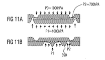
Schließlich zeigen die Fig. 11a und 11b die Situation beim Vorliegen eines Unterdrucks am Fluidauslass, wobei der Referenzdruck P0 1000 hPa betrage, der Einlassdruck P1 ebenfalls 1000 hPa betrage und der :Auslassdruck P2 700 hPa betrage. In dieser Situation wird der Membran-Klappen-Verbund, der durch den Verbund aus Haltestruktur und Verschlusselement gebildet ist, nach unten gezogen, so dass sich das Verschlusselement von der Dichtlippe abhebt und das Ventil geöffnet ist. Diese Situation entspricht' den Verhältnissen beim Saughub einer Pumpe, wobei ausgehend von der Situation in den Fig. 11a und 11b ein Druckausgleich durch ein Nachströmen von Fluid in den Einlass stattfinden wird.Finally, FIGS. 11a and 11b show the situation when there is a negative pressure at the fluid outlet, the reference pressure P0 being 1000 hPa, the inlet pressure P1 also being 1000 hPa and the outlet pressure P2 being 700 hPa. In this situation, the membrane-flap composite, which is formed by the composite of support structure and closure element, pulled down so that the closure element lifts off the sealing lip and the valve is open. This situation corresponds to the conditions during the suction stroke of a pump, whereby, starting from the situation in FIGS. 11a and 11b, a pressure equalization will take place by a subsequent flow of fluid into the inlet.
Wie aus Fig. 11b zu erkennen ist, ist der Hub der Haltestruktur durch den unteren Chip begrenzt, wobei der Hub nie höher sein kann als die Ventilkammerhöhe. Ein solcher mechanischer Anschlag für den Hub der Haltestruktur ist vorteilhaft, da nur reduzierte mechanische Spannungen auf dieselbe einwirken. Jedoch kann das Ventil auch nur maximal bis zu Ventilkammerhöhe geöffnet werden, so dass der Flusswiderstand dadurch beeinflusst werden kann. Die Ventilkammerhöhe ist an sich ein frei wählbarer Parameter, wobei sich jedoch durch eine größere Ventilkammerhöhe das Totkammervolumen erhöht, wenn das Mikroventil als Einlassventil in einer Mikropumpe verwendet wird. Der durch den Anschlag der Haltestruktur an das Verschlusselement bedingte erhöhte Flusswiderstand kann reduziert werden, wenn in dem Versteifungsbereich 390 des Verschlusselements in Fig. 11b ein bzw. mehrere von links nach rechts verlaufende Fluidkanäle vorgesehen werden.As can be seen from Fig. 11b, the stroke of the support structure is limited by the lower chip, wherein the stroke can never be higher than the valve chamber height. Such a mechanical one Stop for the stroke of the support structure is advantageous because only reduced mechanical stresses act on the same. However, the valve can only be opened at maximum up to the valve chamber height, so that the flow resistance can be influenced thereby. As such, the valve chamber height is a freely selectable parameter, but with a larger valve chamber height, the dead space volume increases when the microvalve is used as an inlet valve in a micropump. The increased flow resistance caused by the stop of the retaining structure on the closure element can be reduced if one or more fluid channels extending from left to right are provided in the
Um beim Vorliegen eines Überdrucks am Fluideinlass ein Durchbiegen der Ventilklappenaufhängung nach oben zu vermeiden, können bei allen Ausführungsformen des erfindungsgemäßen Mikroventils zwischen der auslenkbaren Haltestruktur und dem auslenkbaren Verschlusselement Stützelemente gebildet sein, die im geschlossenen Zustand ein unerwünschtes Durchbiegen des Verschlusselements verhindern. Bezug nehmend auf Fig. 8b können derartige Stützelemente 372 beispielsweise rechts und links vom Stößel 326 im Bereich der membranartigen Aufhängungen 368 in die Unterseite des Membranchips 300 strukturiert sein. Diese Stützelemente 372 können gleichzeitig mit dem Stößel und der Dichtlippe in der Unterseite des Membranchips 300 strukturiert werden und die gleiche Höhe oder eine geringere Höhe wie die Dichtlippe und/oder der Stößel aufweisen. Diese Stützelemente dürfen jedoch nicht fest mit dem Klappenchip 302' verbunden sein. Die Ausgestaltung der Stützelemente kann beliebig sein, wobei dieselben die Form einer durchgehenden Leiste auf jeder Seite des Stößels oder die Form von einzelnen Pfosten aufweisen können.In order to avoid upward deflection of the valve flap suspension in the presence of an overpressure at the fluid inlet, in all embodiments of the microvalve according to the invention between the deflectable support structure and the deflectable closure element support elements may be formed, which prevent undesirable bending of the closure element in the closed state. Referring to FIG. 8b,
Im folgenden wird genauer auf das Zusammenwirken der drei Drücke P0, P1 und P2 eingegangen. Der Referenzdruck P0 wird in der Regel der Atmosphärendruck sein, wobei der Referenzdruck aber auch anders gewählt werden kann, wenn der Raum über dem Ventil mit einem definierten Druckreservoir beaufschlagt wird. Das Kraftgleichgewicht gibt folgendes Kriterium für ein Schließen des Ventils: ![]()
![]()
![]()
![]()
Eine Analyse einer Variation des Referenzdrucks P0 ergibt die im folgenden dargelegten Fälle, wobei zu Veranschaulichungszwecken von einem Wert β=0,5 ausgegangen wird.An analysis of a variation of the reference pressure P0 yields the cases set forth below, assuming a value β = 0.5 for illustrative purposes.
Liegt ein Referenzdruck P0 von 0 vor, was einem Vakuum außerhalb des Mikroventils entspricht, ergibt sich aus dem obigen Kriterium P2>-P1. Somit ist das Ventil für alle P1 und P2 doppelt geschlossen, was bedeutet, dass das Ventil nicht geöffnet werden kann. Anders ausgedrückt heißt das, dass, wenn der Referenzdruck auf Vakuum gesetzt wird, das Ventil in keinem Fall geöffnet werden kann.If there is a reference pressure P0 of 0, which corresponds to a vacuum outside the microvalve, the above criterion results in P2> -P1. Thus, the valve is double closed for all P1 and P2, which means that the valve can not be opened. In other words, if the reference pressure is set to vacuum, the valve can not be opened in any case.
Für 0<P0<0,5·P1 ergibt das obige Kriterium: P2>P0-P1.For 0 <P0 <0.5 * P1, the above criterion gives: P2> P0-P1.
Dies bedeutet, dass das Ventil für alle P2 und P1 doppelt geschlossen ist. Auch bei einem Referenzdruck, der kleiner als der halbe Einlassdruck ist, kann somit das Ventil in keinem Fall geöffnet werden.This means that the valve is double closed for all P2 and P1. Even with a reference pressure which is less than half the inlet pressure, thus the valve can be opened under any circumstances.
Für 0,5·P1≤P0≤P1, d. h. P0=α·P1, mit 0,5<α≤1 ergibt das obige Kriterium: P2>P1·(2α-1). Das heißt, dass das Ventil geschlossen bleibt, wenn P2 den Wert P1·(2α-1) überschreitet. Das Ventil öffnet nur, wenn ein Unterdruck P2 auftritt, der geringer ist als P1·(2α-1). Ist somit der Referenzdruck kleiner als P1 aber größer als 0,5·P1, öffnet das Ventil nur bei einem Unterdruck am Auslass.For 0.5 * P1≤P0≤P1, ie P0 = α * P1, where 0.5 <α≤1, the above criterion gives: P2> P1 * (2α-1). This means that the valve remains closed when P2 exceeds P1 · (2α-1). The valve opens only when a negative pressure P2 occurs that is less than P1 · (2α-1). Thus, if the reference pressure is less than P1 but greater than 0.5 · P1, the valve opens only at a negative pressure at the outlet.
Für den Fall, dass der Referenzdruck größer ist als der Einlassdruck, d. h. P0>P1 ergibt das obige Kriterium: P2>2·P0-P1: in diesem Fall muß der Auslassdruck P2 den Einlassdruck P1 übersteigen, um das Ventil zu schließen. Ist somit der Referenzdruck größer als P1 kann das Ventil nur geschlossen gehalten werden, wenn der Auslassdruck P2 den Einlassdruck P1 übersteigt.In the event that the reference pressure is greater than the inlet pressure, d. H. P0> P1 gives the above criterion: P2> 2 · P0-P1: in this case, the outlet pressure P2 must exceed the inlet pressure P1 to close the valve. Thus, if the reference pressure is greater than P1, the valve can only be kept closed when the outlet pressure P2 exceeds the inlet pressure P1.
Schließlich sei noch der Fall betrachtet, bei dem der Referenzdruck größer als der Einlassdruck und größer als der Auslassdruck ist, d. h. P0>P1 und P0>P2. In diesem Fall gilt P2+P1>2·P0. Diese Ungleichung kann für keine Einlassdrücke und Auslassdrücke erfüllt werden, so dass das Ventil in diesem Fall "doppelt offen" ist. Für einen solchen Referenzdruck kann das Ventil somit nicht geschlossen werden.Finally, consider the case where the reference pressure is greater than the inlet pressure and greater than the outlet pressure, d. H. P0> P1 and P0> P2. In this case, P2 + P1> 2 · P0. This inequality can not be satisfied for any inlet pressures and outlet pressures, so the valve is "double-open" in this case. For such a reference pressure, the valve can thus not be closed.
Ein Ventil mit gewünschten Eigenschaften kann durch Vorsehen einer Einrichtung zum Einstellen des Referenzdrucks, der von außen auf die Haltestruktur wirkt, geschaffen werden. Eine solche Einrichtung kann beispielsweise durch einen hermetisch abschließenden Deckel, der bei Herstellung des Ventils als Druckreservoir auf die dem Verschlusselement der Haltestruktur abgewandte Seite der Haltestruktur aufgebracht wird, um einen definierten Druck von z.B. 700 hPa zu liefern, realisiert sein. Ferner kann eine Fluidleitung mit der dem Verschlusselement abgewandten Seite der Haltestruktur verbunden sein, so dass über die Fluidleitung ein vorbestimmter Druck auf die Haltestruktur ausübbar ist, um somit eine pneumatische Steuerung für das Mikroventil zu schaffen. Das erfindungsgemäße Mikroventil kann auch als Sicherheitsventil ausgebildet sein, das offen ist, solange ein Referenzdruck von außen auf die Haltestruktur wirkt, und das schließt, sobald ein entsprechender Referenzdruck nicht mehr vorhanden ist, beispielsweise durch Durchstoßen einer Membran oder dergleichen.A valve with desired characteristics can be provided by providing means for adjusting the reference pressure acting on the support structure from the outside. Such a device can be realized, for example, by a hermetically sealing lid, which, when the valve is produced as a pressure reservoir, is applied to the side of the holding structure facing away from the closure element of the holding structure in order to provide a defined pressure of, for example, 700 hPa. Furthermore, a fluid line can be connected to the side of the holding structure facing away from the closure element, so that a predetermined pressure can be exerted on the holding structure via the fluid line, thus creating a pneumatic control for the microvalve. The microvalve according to the invention can also be designed as a safety valve which is open as long as a reference pressure acts on the holding structure from outside, and this closes as soon as a corresponding reference pressure is no longer present, for example by puncturing a membrane or the like.
Nachdem nunmehr die Druckverhältnisse hinsichtlich des selbstsperrenden Verhaltens des erfindungsgemäßen Mikroventils erläutert wurden, wird nachfolgend Bezug nehmend auf die Fig. 12a bis 12e die Integration eines solchen erfindungsgemäßen Mikroventils als Einlassventil in einer Mikromembranpumpe beschrieben.Having now explained the pressure ratios with regard to the self-locking behavior of the microvalve according to the invention, the integration of such a microvalve according to the invention as an inlet valve in a micromembrane pump will be described below with reference to FIGS. 12a to 12e.
Eine solche erfindungsgemäße Mikromembranpumpe umfasst einen Membranchip 400 und einen Klappenchip 402, wie in Fig. 12b gezeigt ist. Die Chips 400 und 402 können aus den gleichen Materialien und mittels der gleichen Verfahren, die oben bezüglich der Chips 300 und 302 angegeben wurden, hergestellt werden.Such a micromembrane pump according to the invention comprises a
Fig. 12a zeigt eine Draufsicht auf den Membranchip 400, Fig. 12b eine Schnittansicht entlang der Linie S3-S3 von Fig. 12a, Fig. 12c eine Schnittansicht entlang der Linie S4-S4 von Fig. 12a, Fig. 12d eine Schnittansicht entlang der Linie S5-S5 von Fig. 12a und Fig. 12e eine Unteransicht des Membranchips 400.Fig. 12a shows a plan view of the
Im linken Bereich der Mikromembranpumpe ist ein erfindungsgemäßes Mikroventil realisiert, das mit Ausnahme der folgenden Ausnahme beispielsweise dem Bezug nehmend auf die Fig. 8a und 8b beschriebenen Ausführungsbeispiel entspricht. In dem Klappenchip 402 ist bei der in den Fig. 12a bis 12e gezeigten Mikropumpe kein Fluidauslass vorgesehen, sondern vielmehr ist ein Fluidauslass 404 hier in dem Membranchip strukturiert. Der Fluideinlass und das Verschlusselement 340' sind wiederum (vergleichbar mit den Fig. 8a und 8b) über eine Fluidleitung, die in einem Trägerelement vorgesehen sein kann, mit einem Einlassdruck P1 beaufschlagbar.In the left-hand region of the micromembrane pump, a microvalve according to the invention is realized which, with the exception of the following exception, corresponds, for example, to the embodiment described with reference to FIGS. 8a and 8b. In the
In der Oberseite des Membranchips 400 ist ferner eine Ausnehmung 410 zum Erzeugen einer Pumpmembran 412 gebildet. Auf der Pumpmembran ist ein Betätigungsglied 414 vorgesehen, beispielsweise in der Form einer Piezokeramik, die zusammen mit der Membran 412 einen Piezobiegewandler definiert. Wie in Fig. 12e zu sehen ist, ist die Unterseite des Membranchips 400 strukturiert, um zusammen mit einer Ausnehmung in der Oberfläche des Klappenchips 402 eine Pumpkammer 406 zu definieren. Die zusätzliche Absenkung der Pumpkammer in die Oberfläche des Klappenchips 402 dient dabei dazu, um ein besseres Kompressionsverhältnis zu erreichen. Zu diesem Zweck kann die Absenkung kreisförmig ausgebildet sein, wie durch die gestrichelte Linie 416 in Fig. 12a angedeutet ist, um an die Auslenkung der Pumpmembran angepasst zu sein, so dass sich eine bestmögliche Verdrängung des Pumpkammervolumens bei Auslenkung der Pumpmembran 412 nach unten ergibt. An dieser Stelle sei angemerkt, dass der gestrichelte Kreis in Fig. 12a lediglich veranschaulichend im Sinne eines Durchscheinbildes dargestellt ist, da derselbe an sich Teil des Klappenchips 402 ist.In the upper side of the
Am Auslass der Mikromembranpumpe ist ein Rückschlagventil 430 vorgesehen. Wie das Einlassventil und der Pumpkammerbereich ist auch das Rückschlagventil 430 am Auslass durch entsprechende Strukturierungen des Membranchips 400 und des Klappenchips 402 gebildet. Dazu ist in der Unterseite des Membranchips 400 eine Ventilkammer 432 gebildet, die mit der Pumpkammer 406 fluidmäßig verbunden ist. Die Ventilkammer 432 ist von einem Auslassbereich 436, der ebenfalls in der Unterseite des Membranchips 400 strukturiert ist, durch eine Dichtlippe 434 getrennt. In dem Klappenchip 402 ist eine Ventilklappe 437 strukturiert. Bei dem gezeigten Ausführungsbeispiel handelt es sich bei der Ventilklappe 437 um eine dreiseitig eingespannte Ventilklappe, die auf drei Seiten derselben durch membranartige Strukturen 438, 440 und 442 eingespannt ist. An einer vierten Seite ist die Ventilklappe 437, die, wie in den Fig. 12b und 12d zu sehen ist, einen Versteifungsbereich 444 aufweist, nicht eingespannt sondern grenzt an einen Auslass 446 der Mikromembranpumpe. Bei einem Überdruck in der Pumpkammer 406 und somit der Ventilkammer 432 hebt sich die Ventilklappe 436 von der Dichtlippe 434 ab, so dass ein Fluidfluss aus der Pumpkammer zu dem Auslass 446 erfolgen kann. Umgekehrt wirkt das Ventil 430 bei einem Druck P3, d.h. bei einem Überdruck, am Auslass 446 sperrend.At the outlet of the micromembrane pump, a
Wie in Fig. 12d gezeigt ist, wirkt der Druck P3 am Auslass auf die Ventilklappe des dort dargestellten Rückschlagventils. Es ist klar, dass zu diesem Zweck die Mikropumpe entsprechend auf ein Trägerelement aufgebracht sein kann, das eine Auslassfluidleitung besitzt, die an dem Auslass 446 und dem Rückschlagventil 430 mündet, so dass der Druck P3 wie oben angegeben wirkt.As shown in Fig. 12d, the pressure P3 acts at the outlet on the valve flap of the check valve shown there. It will be appreciated that for this purpose, the micropump may be suitably applied to a support member having an outlet fluid conduit opening at the
Alternativ zu dem beschriebenen Rückschlagventil 430 könnte das Auslassventil der erfindungsgemäßen Mikromembranpumpe auch durch ein herkömmliches Rückschlagventil verwendet werden, wie es oben Bezug nehmend auf die Fig. 1a bis 1c beschrieben wurde.As an alternative to the described
Bei der oben Bezug nehmend auf die Fig. 12a bis 12e beschriebenen Mikropumpe ist das doppelt selbstsperrende erfindungsgemäße Mikroventil am Einlass wirksam, um bei Vorliegen eines Überdrucks in der Pumpkammer 406, die mit dem Fluidauslass 404 des Mikroventils fluidmäßig verbunden ist, einen Rückfluss durch die Einlassöffnungen im wesentlichen zu verhindern.In the micropump described above with reference to FIGS. 12a-12e, the double-self-locking microvalve of the present invention operates at the inlet to provide backflow through the inlet ports when there is an overpressure in the
Bezug nehmend auf die Figuren wurden oben bevorzugte Ausführungsbeispiele der vorliegenden Erfindung näher erläutert. Es ist für Fachleute klar, dass zahlreiche Modifikationen hinsichtlich der beschriebenen Ausführungsbeispiele existieren. Insbesondere könnten Strukturierungen, die bei den obigen Ausführungsbeispielen jeweils in einer Oberfläche von einem der Chips gebildet sind, auch durch Strukturierungen in beiden Oberflächen dieses Chips bzw. in der mit dem Chip verbundenen Oberfläche des anderen Chips gebildet sein, um die entsprechende Funktionalität zu erhalten. Darüber hinaus müssen, wie bereits oben erwähnt wurde, die jeweiligen Ausnehmungen nicht die dargestellte abgeschrägte Form aufweisen, die typisch für eine Strukturierung von Siliziumsubstraten unter Verwendung eines KOH-Ätzens ist. Vielmehr können die jeweiligen Strukturen andere Formen aufweisen, insbesondere wenn das erfindungsgemäße Mikroventil bzw. die erfindungsgemäße Mikromembranpumpe durch andere Materialien als Silizium implementiert werden, beispielsweise Kunststoffe oder Metalle.Referring to the figures, preferred embodiments of the present invention have been explained in detail above. It will be apparent to those skilled in the art that numerous modifications exist with respect to the described embodiments. In particular, structurings, which in the above embodiments are each formed in a surface of one of the chips, could also be formed by structuring in both surfaces of this chip or in the surface of the other chip connected to the chip in order to obtain the corresponding functionality. In addition, as already mentioned above, the respective recesses do not have to be chamfered Having a shape that is typical for structuring of silicon substrates using a KOH etching. Rather, the respective structures may have other shapes, in particular if the microvalve according to the invention or the micromembrane pump according to the invention are implemented by materials other than silicon, for example plastics or metals.
Claims (17)
- Normally closed microvalve, comprising:a fluid inlet (330);a fluid outlet (332);a deflectable closing element (340; 340'), which, in the closed state of the microvalve, is seated on a sealing lip (324), such that the fluid inlet (330) is fluidically disconnected from the fluid outlet (332), and, in the opened state of the microvalve, is spaced apart from the sealing lip (324); anda deflectable holding structure (310; 306), which is connected to the closing element (340; 340'), such that, between the same, a space (320) exists, which is in fluidic communication to the fluid outlet (332),wherein an influence of force onto the holding structure and the closing element in a first direction provides an opening action, and an influence of force onto the holding structure and the closing element in a second direction provides a closing action,with the fluid inlet (330) and the closing element (340; 340') being arranged such that a pressure at the fluid inlet (330) exerts a force into the second direction, characterized inwith an effective area of the holding structure (310; 360), which, when a pressure is applied to the fluid outlet (332), exerts a force into the second direction, is greater than an effective area of the closing element (340; 340'), which, when a pressure is applied to the fluid outlet (332), causes a force in the first direction, andthat the deflectable holding structure (310; 360) comprises a stiffened diaphragm structure.
- Microvalve in accordance with claim 1, wherein the deflectable closing element (340, 340') comprises a stiffened or non-stiffened diaphragm structure.
- Microvalve in accordance with claim 2, wherein the holding structure (310; 360) is a circumferentially fixed, stiffened diaphragm structure, and wherein the closing element (340; 340') is a stiffened or non-stiffened diaphragm structure fixed at two sides thereof.
- Microvalve in accordance with claim 3, comprising two fluid inlets (330) at the non-fixed sides of the closing element (340, 340') and a sealing lip (324) for each of the fluid inlets (330).
- Microvalve in accordance with claim 4, comprising a fluid outlet (332) on one or both fixed sides of the closing element (340, 340').
- Microvalve in accordance with one of claims 2 to 5, wherein the stiffened diaphragm structure of the holding structure (310; 360) comprises a greater area than the stiffened or non-stiffened diaphragm structure of the closing element (340; 340').
- Microvalve in accordance with one of claims 1 to 6, wherein the holding structure (310; 360) and the closing element (340; 340') are connected by means of a connection piece (326), which connects a central area of the holding structure (310; 360) to a central area of the closing element (340, 340').
- Microvalve in accordance with claim 7, wherein the holding structure (310; 360) is formed in a first layer (300; 300'; 400) and the closing element (340; 340') is formed in a second layer (302; 302'; 402), with the fluid inlet (330), the fluid outlet (332; 404), the sealing lip (324), the space (320) and the connection piece (326) are further structured in these two layers with the layers being connected at respective first surfaces of the same.
- Microvalve in accordance with claim 8, wherein the sealing lip (324), the space (320) and the connection piece (326) are structured in the first surface of the first layer (300; 300'; 400) and the fluid inlet (330) and the fluid outlet (332) are structured in the second layer.
- Microvalve in accordance with one of claims 1 to 9, wherein, between the deflectable holding structure (310; 360) and the deflectable closing element (340; 340') support elements are formed, which, in the closed state, prevent an undesired bending of the closing element (340; 340').
- Microvalve in accordance with one of claims 1 to 10, wherein the holding structure (310; 360) and the closing element (340; 340') are formed to be deflected by the respectively prevailing pressures, with no active actuation means for the holding structure or the closing element being provided.
- Microvalve in accordance with one of claims 1 to 11, wherein a reference pressure acting on the holding structure provides an opening action, when a pressure is applied to the fluid outlet, which, as compared to the reference pressure, represents a negative pressure.
- Microvalve in accordance with one of claims 1 to 12, having a means for adjusting a reference pressure acting onto the holding structure.
- Micropump with a microvalve in accordance with one of claims 1 to 13 as an inlet valve.
- Micropump in accordance with claim 14, which, as an outlet valve, comprises a passive non-return valve.
- Micropump in accordance with claim 14, wherein the inlet valve and the pump structures of the micropump are structured in two layers (400, 402).
- Micropump in accordance with claim 15, wherein the inlet valve, pump structures of the micropump and the outlet valve are structured in two layers (400, 402).
Applications Claiming Priority (1)
| Application Number | Priority Date | Filing Date | Title |
|---|---|---|---|
| PCT/EP2003/002491 WO2004081390A1 (en) | 2003-03-11 | 2003-03-11 | Microvalve that is doubly closed in a normal manner |
Publications (2)
| Publication Number | Publication Date |
|---|---|
| EP1576294A1 EP1576294A1 (en) | 2005-09-21 |
| EP1576294B1 true EP1576294B1 (en) | 2006-08-09 |
Family
ID=32981704
Family Applications (1)
| Application Number | Title | Priority Date | Filing Date |
|---|---|---|---|
| EP03711974A Expired - Fee Related EP1576294B1 (en) | 2003-03-11 | 2003-03-11 | Microvalve that is doubly closed in a normal manner |
Country Status (5)
| Country | Link |
|---|---|
| US (1) | US7631852B2 (en) |
| EP (1) | EP1576294B1 (en) |
| AU (1) | AU2003218730A1 (en) |
| DE (1) | DE50304618D1 (en) |
| WO (1) | WO2004081390A1 (en) |
Cited By (3)
| Publication number | Priority date | Publication date | Assignee | Title |
|---|---|---|---|---|
| CN104169583A (en) * | 2012-12-21 | 2014-11-26 | 弗兰霍菲尔运输应用研究公司 | Pump arrangement comprising a safety valve arrangement |
| DE102015224622A1 (en) | 2015-12-08 | 2017-06-08 | Fraunhofer-Gesellschaft zur Förderung der angewandten Forschung e.V. | FREISTRAHLDOSIERSYSTEM |
| DE102015224619A1 (en) | 2015-12-08 | 2017-06-08 | Fraunhofer-Gesellschaft zur Förderung der angewandten Forschung e.V. | micro-dosing system |
Families Citing this family (14)
| Publication number | Priority date | Publication date | Assignee | Title |
|---|---|---|---|---|
| DE102006001240B4 (en) * | 2006-01-06 | 2009-07-09 | Fraunhofer-Gesellschaft zur Förderung der angewandten Forschung e.V. | Fuel cell system with a controllable gas generating device, fuel cell and method for operating the fuel cell system |
| DE102007035721B4 (en) * | 2007-07-30 | 2019-02-07 | Robert Bosch Gmbh | Microvalve, method of manufacturing a microvalve and micropump |
| US8485793B1 (en) * | 2007-09-14 | 2013-07-16 | Aprolase Development Co., Llc | Chip scale vacuum pump |
| WO2009065427A1 (en) * | 2007-11-23 | 2009-05-28 | Fraunhofer-Gesellschaft zur Förderung der angewandten Forschung e.V. | Pump arrangement having safety valve |
| DE102007061920A1 (en) * | 2007-12-21 | 2009-06-25 | Paritec Gmbh | Chamber, pump with chamber and method for the production of chambers |
| EP2542810B1 (en) | 2010-03-05 | 2015-04-15 | Fraunhofer-Gesellschaft zur Förderung der Angewandten Forschung e.V. | Method for manufacturing a micro pump and micro pump |
| US9618129B2 (en) | 2010-10-07 | 2017-04-11 | Vanderbilt University | Normally closed microvalve and applications of the same |
| US10078075B2 (en) | 2011-12-09 | 2018-09-18 | Vanderbilt University | Integrated organ-on-chip systems and applications of the same |
| WO2014123600A2 (en) * | 2012-12-10 | 2014-08-14 | Vanderbilt University | Normally closed microvalve and applications of the same |
| DE102011109944B4 (en) * | 2011-08-10 | 2018-10-25 | Bürkert Werke GmbH | Manufacturing process for microvalves |
| JP5533823B2 (en) * | 2011-09-06 | 2014-06-25 | 株式会社村田製作所 | Fluid control device |
| TWI557321B (en) * | 2015-06-25 | 2016-11-11 | 科際精密股份有限公司 | Piezoelectric pump and operating method thereof |
| ITUB20151781A1 (en) * | 2015-07-02 | 2017-01-02 | Milano Politecnico | MICROPUMP WITH ELECTROSTATIC IMPLEMENTATION |
| DE102019211941B3 (en) | 2019-08-08 | 2020-10-15 | Fraunhofer-Gesellschaft zur Förderung der angewandten Forschung e.V. | MICROSTRUCTURED FLUID FLOW CONTROL DEVICE |
Family Cites Families (12)
| Publication number | Priority date | Publication date | Assignee | Title |
|---|---|---|---|---|
| CH564163A5 (en) * | 1972-11-13 | 1975-07-15 | Arisland K O | |
| US4911616A (en) * | 1988-01-19 | 1990-03-27 | Laumann Jr Carl W | Micro miniature implantable pump |
| DE3919876A1 (en) * | 1989-06-19 | 1990-12-20 | Bosch Gmbh Robert | MICRO VALVE |
| JP3035854B2 (en) * | 1995-09-15 | 2000-04-24 | ハーン−シッカート−ゲゼルシャフト フア アンゲワンテ フォルシュンク アインゲトラーゲナー フェライン | Fluid pump without check valve |
| US7052594B2 (en) * | 2002-01-31 | 2006-05-30 | Sri International | Devices and methods for controlling fluid flow using elastic sheet deflection |
| DE19719862A1 (en) | 1997-05-12 | 1998-11-19 | Fraunhofer Ges Forschung | Micro diaphragm pump |
| WO1999009321A1 (en) * | 1997-08-20 | 1999-02-25 | Westonbridge International Limited | Micro pump comprising an inlet control member for its self-priming |
| WO1999038551A1 (en) * | 1998-02-02 | 1999-08-05 | Medtronic, Inc. | Implantable drug infusion device having a safety valve |
| DE10048376C2 (en) | 2000-09-29 | 2002-09-19 | Fraunhofer Ges Forschung | Micro valve with a normally closed state |
| US6554591B1 (en) * | 2001-11-26 | 2003-04-29 | Motorola, Inc. | Micropump including ball check valve utilizing ceramic technology and method of fabrication |
| US7025324B1 (en) * | 2002-01-04 | 2006-04-11 | Massachusetts Institute Of Technology | Gating apparatus and method of manufacture |
| US7032608B2 (en) * | 2004-09-01 | 2006-04-25 | Harris Corporation | Microfluidic check-valve embedded in LCP |
-
2003
- 2003-03-11 DE DE50304618T patent/DE50304618D1/en not_active Expired - Lifetime
- 2003-03-11 AU AU2003218730A patent/AU2003218730A1/en not_active Abandoned
- 2003-03-11 EP EP03711974A patent/EP1576294B1/en not_active Expired - Fee Related
- 2003-03-11 WO PCT/EP2003/002491 patent/WO2004081390A1/en not_active Application Discontinuation
-
2005
- 2005-09-09 US US11/223,828 patent/US7631852B2/en not_active Expired - Fee Related
Cited By (7)
| Publication number | Priority date | Publication date | Assignee | Title |
|---|---|---|---|---|
| CN104169583A (en) * | 2012-12-21 | 2014-11-26 | 弗兰霍菲尔运输应用研究公司 | Pump arrangement comprising a safety valve arrangement |
| US9546651B2 (en) | 2012-12-21 | 2017-01-17 | Fraunhofer-Gesellschaft Zur Foerderung Der Angewandten Forschung E.V. | Pump arrangement comprising a safety valve arrangement |
| CN104169583B (en) * | 2012-12-21 | 2017-03-01 | 弗劳恩霍夫应用研究促进协会 | Pump arrangement including relief valve arrangement |
| DE102015224622A1 (en) | 2015-12-08 | 2017-06-08 | Fraunhofer-Gesellschaft zur Förderung der angewandten Forschung e.V. | FREISTRAHLDOSIERSYSTEM |
| DE102015224619A1 (en) | 2015-12-08 | 2017-06-08 | Fraunhofer-Gesellschaft zur Förderung der angewandten Forschung e.V. | micro-dosing system |
| US10550833B2 (en) | 2015-12-08 | 2020-02-04 | Fraunhofer-Gesellschaft Zur Foerderung Der Angewandten Forschung E.V. | Microdosing system |
| US11022470B2 (en) | 2015-12-08 | 2021-06-01 | Fraunhofer-Gesellschaft Zur Foerderung Der Angewandten Forschung E.V. | Free-jet dosing system |
Also Published As
| Publication number | Publication date |
|---|---|
| WO2004081390A1 (en) | 2004-09-23 |
| DE50304618D1 (en) | 2006-09-21 |
| EP1576294A1 (en) | 2005-09-21 |
| US7631852B2 (en) | 2009-12-15 |
| US20060027772A1 (en) | 2006-02-09 |
| AU2003218730A1 (en) | 2004-09-30 |
Similar Documents
| Publication | Publication Date | Title |
|---|---|---|
| EP1320686B1 (en) | Micro valve normally in a closed position | |
| EP1576294B1 (en) | Microvalve that is doubly closed in a normal manner | |
| EP2220371B1 (en) | Pump arrangement having safety valve | |
| EP1458977B2 (en) | Peristaltic micropump | |
| DE102007035721B4 (en) | Microvalve, method of manufacturing a microvalve and micropump | |
| EP0914564B1 (en) | Piezo-electrically actuated microvalve | |
| EP2531760B1 (en) | Micro-fluidic component for manipulating a fluid, and microfluidic chip | |
| EP2556282B1 (en) | Micro valve with elastic deformable seal lip, method of producing and micrropump | |
| EP2207963B1 (en) | Pump and pump arrangement | |
| EP0521117B1 (en) | Microvalve | |
| DE69922288T2 (en) | Micropump and manufacturing process for the micropump | |
| DE4138491C2 (en) | Micromechanical valve for micromechanical dosing devices | |
| DE102011005811A1 (en) | Microfluidic valve and microfluidic platform | |
| DE102019211941B3 (en) | MICROSTRUCTURED FLUID FLOW CONTROL DEVICE | |
| DE10135569B4 (en) | Micromechanical component | |
| DE102010028524A1 (en) | Microfluidic component, in particular peristaltic micropump, and method for its production | |
| WO2008025601A1 (en) | Method of producing components for controlling a fluid flow and components produced by this method | |
| DE19844518A1 (en) | Hydraulic flow amplifier for microsystems with drive diaphragm bending under energy supply | |
| EP2759751B1 (en) | Method for producing a normally closed non-return valve for micro-fluid components comprising a polymer layer system and non-return valve | |
| DE10243997B4 (en) | Micro valve in multi-layer construction | |
| DE19511022C1 (en) | Micro=mechanical valve for micro dosing |
Legal Events
| Date | Code | Title | Description |
|---|---|---|---|
| PUAI | Public reference made under article 153(3) epc to a published international application that has entered the european phase |
Free format text: ORIGINAL CODE: 0009012 |
|
| 17P | Request for examination filed |
Effective date: 20050713 |
|
| AK | Designated contracting states |
Kind code of ref document: A1 Designated state(s): AT BE BG CH CY CZ DE DK EE ES FI FR GB GR HU IE IT LI LU MC NL PT RO SE SI SK TR |
|
| AX | Request for extension of the european patent |
Extension state: AL LT LV MK |
|
| GRAP | Despatch of communication of intention to grant a patent |
Free format text: ORIGINAL CODE: EPIDOSNIGR1 |
|
| DAX | Request for extension of the european patent (deleted) | ||
| RBV | Designated contracting states (corrected) |
Designated state(s): DE FR GB |
|
| GRAS | Grant fee paid |
Free format text: ORIGINAL CODE: EPIDOSNIGR3 |
|
| GRAA | (expected) grant |
Free format text: ORIGINAL CODE: 0009210 |
|
| AK | Designated contracting states |
Kind code of ref document: B1 Designated state(s): DE FR GB |
|
| REG | Reference to a national code |
Ref country code: GB Ref legal event code: FG4D Free format text: NOT ENGLISH |
|
| REF | Corresponds to: |
Ref document number: 50304618 Country of ref document: DE Date of ref document: 20060921 Kind code of ref document: P |
|
| GBT | Gb: translation of ep patent filed (gb section 77(6)(a)/1977) |
Effective date: 20061023 |
|
| RAP2 | Party data changed (patent owner data changed or rights of a patent transferred) |
Owner name: FRAUNHOFER-GESELLSCHAFT ZUR FOERDERUNG DER ANGEWAN |
|
| ET | Fr: translation filed | ||
| PLBE | No opposition filed within time limit |
Free format text: ORIGINAL CODE: 0009261 |
|
| STAA | Information on the status of an ep patent application or granted ep patent |
Free format text: STATUS: NO OPPOSITION FILED WITHIN TIME LIMIT |
|
| 26N | No opposition filed |
Effective date: 20070510 |
|
| REG | Reference to a national code |
Ref country code: FR Ref legal event code: PLFP Year of fee payment: 14 |
|
| REG | Reference to a national code |
Ref country code: FR Ref legal event code: PLFP Year of fee payment: 15 |
|
| REG | Reference to a national code |
Ref country code: FR Ref legal event code: PLFP Year of fee payment: 16 |
|
| PGFP | Annual fee paid to national office [announced via postgrant information from national office to epo] |
Ref country code: FR Payment date: 20210319 Year of fee payment: 19 |
|
| PGFP | Annual fee paid to national office [announced via postgrant information from national office to epo] |
Ref country code: DE Payment date: 20210323 Year of fee payment: 19 Ref country code: GB Payment date: 20210324 Year of fee payment: 19 |
|
| REG | Reference to a national code |
Ref country code: DE Ref legal event code: R119 Ref document number: 50304618 Country of ref document: DE |
|
| GBPC | Gb: european patent ceased through non-payment of renewal fee |
Effective date: 20220311 |
|
| PG25 | Lapsed in a contracting state [announced via postgrant information from national office to epo] |
Ref country code: GB Free format text: LAPSE BECAUSE OF NON-PAYMENT OF DUE FEES Effective date: 20220311 Ref country code: FR Free format text: LAPSE BECAUSE OF NON-PAYMENT OF DUE FEES Effective date: 20220331 Ref country code: DE Free format text: LAPSE BECAUSE OF NON-PAYMENT OF DUE FEES Effective date: 20221001 |