EP1573933B1 - Method and system for receiving an ultra-wideband signal with a self-adapting number of propagation paths - Google Patents
Method and system for receiving an ultra-wideband signal with a self-adapting number of propagation paths Download PDFInfo
- Publication number
- EP1573933B1 EP1573933B1 EP03815405A EP03815405A EP1573933B1 EP 1573933 B1 EP1573933 B1 EP 1573933B1 EP 03815405 A EP03815405 A EP 03815405A EP 03815405 A EP03815405 A EP 03815405A EP 1573933 B1 EP1573933 B1 EP 1573933B1
- Authority
- EP
- European Patent Office
- Prior art keywords
- correlation
- direct
- pulses
- elementary
- pulse
- Prior art date
- Legal status (The legal status is an assumption and is not a legal conclusion. Google has not performed a legal analysis and makes no representation as to the accuracy of the status listed.)
- Expired - Lifetime
Links
- 238000000034 method Methods 0.000 title claims abstract description 44
- 239000002131 composite material Substances 0.000 claims abstract description 29
- 230000005540 biological transmission Effects 0.000 claims description 38
- 230000037361 pathway Effects 0.000 claims description 19
- 230000001902 propagating effect Effects 0.000 claims description 13
- 230000008034 disappearance Effects 0.000 claims description 8
- 230000000717 retained effect Effects 0.000 claims description 7
- 230000000295 complement effect Effects 0.000 claims description 3
- 230000008569 process Effects 0.000 abstract description 10
- 238000001514 detection method Methods 0.000 description 4
- 238000010586 diagram Methods 0.000 description 3
- 230000006870 function Effects 0.000 description 3
- 230000010354 integration Effects 0.000 description 3
- 230000003044 adaptive effect Effects 0.000 description 2
- 230000008859 change Effects 0.000 description 2
- 238000001228 spectrum Methods 0.000 description 2
- 230000001360 synchronised effect Effects 0.000 description 2
- 230000002123 temporal effect Effects 0.000 description 2
- RTZKZFJDLAIYFH-UHFFFAOYSA-N Diethyl ether Chemical compound CCOCC RTZKZFJDLAIYFH-UHFFFAOYSA-N 0.000 description 1
- 235000008694 Humulus lupulus Nutrition 0.000 description 1
- 241000897276 Termes Species 0.000 description 1
- 239000000470 constituent Substances 0.000 description 1
- 230000003247 decreasing effect Effects 0.000 description 1
- 238000005516 engineering process Methods 0.000 description 1
- 230000012447 hatching Effects 0.000 description 1
- 230000006872 improvement Effects 0.000 description 1
- 230000004048 modification Effects 0.000 description 1
- 238000012986 modification Methods 0.000 description 1
- 238000001208 nuclear magnetic resonance pulse sequence Methods 0.000 description 1
- 230000008054 signal transmission Effects 0.000 description 1
- 230000003595 spectral effect Effects 0.000 description 1
Images


Classifications
-
- H—ELECTRICITY
- H04—ELECTRIC COMMUNICATION TECHNIQUE
- H04B—TRANSMISSION
- H04B1/00—Details of transmission systems, not covered by a single one of groups H04B3/00 - H04B13/00; Details of transmission systems not characterised by the medium used for transmission
- H04B1/69—Spread spectrum techniques
- H04B1/7163—Spread spectrum techniques using impulse radio
- H04B1/719—Interference-related aspects
-
- H—ELECTRICITY
- H04—ELECTRIC COMMUNICATION TECHNIQUE
- H04B—TRANSMISSION
- H04B1/00—Details of transmission systems, not covered by a single one of groups H04B3/00 - H04B13/00; Details of transmission systems not characterised by the medium used for transmission
- H04B1/69—Spread spectrum techniques
- H04B1/7163—Spread spectrum techniques using impulse radio
- H04B1/71637—Receiver aspects
Definitions
- the invention relates to a method and a system for receiving an ultra-broadband signal with a number of self-adaptive propagation paths.
- the technique of radio communications in ultra-wide band signal does not use a carrier frequency. Instead of modulating a signal or carrier carrier wave, the information to be transmitted is transmitted directly in baseband, using very short carrier pulses, less than a nanosecond, and therefore a very large bandwidth , several GHz.
- a UWB signal is not a continuous signal but, on the contrary, a train of very short pulses and very low duty cycle.
- the multiple access to the transmission by such a signal is realized, usually, making time hops (Time Hopping) governed by a pseudo random sequence.
- the signal can be modulated in amplitude, by the form factor or even the delay of the successive pulses.
- UWB signal transmission and reception techniques are sui generis techniques, approaching spread spectrum signal detection techniques.
- UWB "rake" signal receivers are designed to operate in disturbed environments, where the location topology creates complex, variable or slowly varying transmission channels due to multiple multiple secondary propagation paths. and, in practice, prohibits the existence of a propagation path in direct vision.
- UWB signal receivers known from the state of the art usually have a so-called "rake" structure inspired by those used for spread spectrum signal receivers.
- the aforementioned UWB receivers comprise a "finger" rake reception branch, each branch receiving a particular reception path.
- the output of each of the reception branches is recombined, after weighting, ( ⁇ 1 , ... ⁇ j , ⁇ N , according to the strategy adopted by the receiver designer.
- a receiving branch is constituted by an analog correlator, a correlation pattern generator and an analog integrator. The continuation of the path relative to the reception branch in question is ensured by the control logic of the receiver.
- the control logic of the receiver triggers the pattern generation corresponding to the arrival times of a pulse.
- the latter generates a correlation pattern designed to have a high intercorrelation value with the received pulse and a zero intercorrelation value in the presence of white noise.
- a large intermediate intercorrelation value indicates the presence of a direct or secondary pulse.
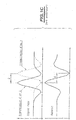
- the figure 1C represents, by way of illustration, an example of this principle in the case of a 2-PPM digital modulation, the transmission of binary values 0 and 1 being represented by the transmission of two pulses A and B offset temporally.
- the correlation pattern is designed so that the value of the cross-correlation coefficient is positive in the presence of an unshifted pulse (A), corresponding to the transmission of a zero but negative value in the presence of a shifted pulse (B) , corresponding to the transmission of a value one, and zero in the absence of pulses.
- the correlation pattern is thus symmetrical with respect to a center of asymmetry.
- FIG. figure 1D Another concrete example illustrated in the case of a PPM modulation with two simultaneous users each having a pseudo random sequence is represented in FIG. figure 1D .
- the symbol is repeated three times, each user thus emitting three pulses, representative of the same symbol.
- the symbol time T s is divided into three frames Tf in which each user codes a single single pulse.
- each pulse is shifted by a time interval ⁇ with respect to the beginning of each elementary frame interval when the bit transmission represented is that of the value 1 instead of the value 0, in the absence of an offset.
- Such receivers are therefore confined to high-end applications, for which the cost criterion is secondary vis-à-vis that of the overall quality performance of the link.
- UWB all-digital rake receiver solutions have been envisaged, in which the received signal is directly digitized at the antenna output. Although, because of purely signal processing software digitized supra, the structure of such receivers is no longer in connection with the traditional rake architecture, such solutions are not viable at present because the current analog-digital converters are not suitable for such use, and digital processing to perform on the aforementioned digital signals can not be performed in real time by the current digital signal processors.
- Another object of the present invention is the implementation of a method and a system for receiving a UWB signal by means of which the implementation costs are substantially reduced, because of the aforementioned simplification.
- Another object of the present invention is the implementation of a method and a system for receiving an ultra-broadband signal by which, despite the significant simplification of the structure used, an improvement in the quality Linkage and overall performance is significantly achieved due to the lack of hardware limitation in the number of main and secondary propagation paths actually handled.
- Another object of the present invention is, finally, because of the absence of hardware limitation of the number of main and secondary paths actually mentioned above, the implementation of a method and a system for receiving an ultra signal. a large band with a number of propagation paths actually treated as auto-adaptive, which makes it possible to optimize the quality of the radio link between transmitter and receiver, even in the presence of a transmission channel originating from a variable severe environment.
- the method and the UWB reception system, objects of the present invention find application to the radio link of domestic appliances or professionals of any type, especially in environment corresponding to a transmission channel over the air path that is substantially disturbed or variable.
- the receiving method of the invention receiving a sequence of successive modulated direct pulses over a symbol time T s , each pulse propagating along a direct propagation path with which a plurality of successive secondary impulses distinct, each propagating along a secondary propagation path distinct from the direct propagation path.
- each direct pulse corresponds to a shortest propagation time
- each distinct successive secondary pulse associated with the aforementioned direct pulse, then being successively shifted in time with respect to the moment of reception, of the direct impulse to which these latter are associated.
- the direct and secondary propagation paths in no way prejudge the number of reflections of the corresponding pulse propagating on these paths.
- the successive distinct secondary pulses are generated by a substantially increasing number of reflections, each reflection being the seat of attenuation.
- the successive distinct secondary pulses are considered to have a substantially decreasing amplitude or energy as a function of their reception rank.
- pulses ID ij are considered , these pulses corresponding, for example, to the pulses emitted, as represented in FIG. figure 1D when the modulation is of type 2-PPM for example.
- the index i denotes the user 1 or 2
- the index j denotes the rank of the pulse transmitted in each frame T f according to the pseudo-random code assigned to each user.
- the time shift ⁇ is the same as in the case of the figure 1 D for simplification.
- the method which is the subject of the invention then consists in receiving, in a step A, the succession of successive direct pulses modulated and the plurality of secondary pulses associated with each of the successive direct pulses modulated on the same receiving circuit.
- i and j represent the user reference, respectively the frame reference in the symbol time T s and k represents the rank of the received pulse, direct pulse and / or secondary pulse.
- the receiving step A is then followed by a step B consisting of generating, by calculation, a composite correlation pattern constituted by a sequence of elementary correlation patterns.
- each elementary correlation pattern corresponds, in the nonlimiting example of the 2-PPM modulation, to the so-called template signal represented in FIG. figure 1C .
- the sequence of elementary correlation patterns comprises a first elementary correlation pattern associated with each forward pulse, that is, any pulse corresponding in position in each frame T f to the position given by the pseudo-random code assigned to each user and, of course, successive elementary correlation patterns each associated with a successive secondary pulse of rank k, k ⁇ [1, N].
- the sliding secondary correlation detection of the set of direct or secondary pulses received over a symbol time is carried out by way of non-limiting example. It is indicated, in fact, that the calculation thus carried out on a symbol time can then be used for the next symbol time, due to the fact that, on a symbol time, where appropriate on two consecutive symbol times, the transmission channel is considered substantially invariable.
- the process of implementing and calculating the composite correlation pattern will be described in more detail in the description.
- Step B is then followed by a step C of calculating the value of the global intercorrelation coefficient
- GCC means the value of the overall cross-correlation coefficient obtained
- the value of the global intercorrelation coefficient GCC is thus constituted by the sum of the intercorrelation coefficients of each of the direct and secondary pulses obtained for each of the modulated pulses transmitted for the same symbol and represents a global correlation value of the symbol. transmitted for each user.
- the operation of calculating the global intercorrelation coefficient thus comprises, with reference to step C of the figure 2 the calculation of the elementary intercorrelation coefficient between each elemental intercorrelation pattern and the direct impulse respectively the secondary impulse associated with each of the elementary intercorrelation patterns, and then the integration, on the symbol time T s , of the set of elemental intercorrelation coefficient values.
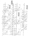
- the process of calculating the value of the global intercorrelation coefficient GCC is then performed, as shown in FIG. Figures 3C , then 3D, for each of the users and, of course, for the direct pulses and the secondary pulses associated therewith from the composite correlation pattern, and the succession of the aforementioned pulses.
- the discrimination the rank of the secondary pulses is not essential, only the position of these pulses in a symbol time T s being finally taken into consideration.
- the method that is the subject of the present invention thus appears to be particularly remarkable in that the number of pulses finally retained for performing the computation operation of the composite correlation pattern and then the value of the overall intercorrelation coefficient can be high. and easily selected, for example, at a number of 10 secondary pulses for each direct pulse according to the characteristics of use and implementation of the method which is the subject of the invention,
- the choice of the number of pulses retained may be guided by considerations relating either to the amplitude and / or energy level of the secondary pulses or, more simply, to the number of pulses retained.
- the number of secondary pulses retained can consist in discriminating any direct pulse of the same frame and in retaining the secondary pulses between two successive direct pulses or even three successive direct pulses.
- the number of secondary pulses thus retained makes it possible to define and retain the first N paths.
- Another possibility for the choice of the number of secondary pulses may consist, for the countable set of direct pulses and secondary pulses considered, to retain N paths for which the amplitude or the energy of the direct pulse respectively secondary pulses are maximum.
- the number N of paths selected may be adapted either according to a selection criterion of the first N paths for execution of a faster processing or, on the contrary, according to a selection criterion of N paths corresponding to an amplitude. and / or a maximum energy of the direct pulse and secondary pulses depending on the propagation conditions.
- a mode of operation thus makes it possible to optimize the quality of the ultra-wideband signal link.
- this process consists, in fact, of establishing by correlation on at least one symbol time T s , an image of the transmission channel in terms of direct pulses and of secondary pulses of propagation time and difference in propagation time between direct pulses and successive secondary pulses, then to update, by sliding correlation, the image of the transmission channel to update the appearance and disappearance of paths of secondary propagation, the case appropriate direct propagation paths, and establish, over at least one symbol time, the composite correlation pattern as the updated image of the transmission channel.
- the acquisition and updating channel 1 makes it possible, by sliding correlation, to update the appearance and disappearance of secondary propagation paths, as well as of the main propagation path and of course, to establish on at least one symbol time the composite correlation pattern previously mentioned in the description.
- the acquisition and updating channel 1 makes it possible to deliver a path list signal representative of the image of the transmission channel, the list of paths being denoted LT on the figure 4 , this list being delivered for example for each symbol time T s .
- the path list signal can correspond to the designation of the instants, on the symbol time, to which each elementary correlation pattern must be successively generated to achieve the aforementioned composite correlation pattern.
- the instants designated by the path list signal LT are, of course, offset in time with respect to the instant of the first elementary correlation pattern associated with each direct pulse of the difference in propagation time between the propagation time of the direct pulse on the direct propagation path and the propagation time of the associated secondary pulse propagating on the corresponding secondary propagation path.
- system which is the subject of the present invention comprises a single correlation channel 2 receiving the direct and secondary propagation path list signal LT, the unique correlation path 2 making it possible to calculate the value of the overall intercorrelation coefficient GCC.
- the aforementioned acquisition and updating channel 1 comprises a global acquisition correlation path and this path, denoted 1 1 receiving the sequence of successive pulses delivered by the common reception circuits and delivering a overall acquisition correlation coefficient value, denoted GAC 1 .
- the global acquisition correlation path 1 1 comprises a correlator 1 12 , an integrator or summator 1 13 and a generator 11 of the elementary synchronization pattern SEM 1 .
- the route of acquisition and updating 1 further comprises a module 1 0 exploration and tracking channel, which receives the global correlation coefficient value acquisition GAC 1 delivered by the global correlation pathway of acquisition and tracking 1 1 previously mentioned, as well as the value of the global intercorrelation coefficient GCC delivered by the path 2 of single correlation.
- Module 1 0 channel exploration and tracking outputs the direct propagation path list signal LT and secondary previously described in the description relating to the implementation of the method of the invention, as well as a signal synchronization ST 1 on the symbol time at the elementary synchronization pattern generator 1 11 constituting the acquisition and updating channel 1 1 .
- the generator of elementary synchronization patterns 11 delivers, after acquisition of the image of the sliding correlation channel, a set of elementary synchronization patterns SEM 1 forming an acquisition correlation pattern, which corresponds substantially to the existence of an elementary correlation pattern generated at the predictable moment of existence of each direct pulse or of secondary pulses associated therewith, in the absence of significant variability of the transmission channel.
- the synchronization signal ST 1 is, of course, synchronized to the symbol time.
- the channel exploration and tracking module 1 0 can, from the pseudo-random codes of each of the users, and therefore the position of the direct pulses generated by each of these, or from the list of paths LT, generating a synchronization signal ST 1 , as described above in the description.
- the selection of the instants of creation of the elementary synchronization patterns may be performed from the pseudo-random codes held by the elementary synchronization pattern generator 11 , the synchronization signal ST 1 then being reduced to a series of equidistant successive pulses constituting a time base for example, the equidistant pulses being separated by a time interval corresponding to the discrimination resolution of two successive direct and / or secondary pulses. These pulses are repeated at each symbol time T 5 .
- the aforesaid procedure enables the sliding path correlation list LT to be updated for the next symbol time from the value of the global correlation coefficient GCC delivered by the single correlation path for the preceding symbol time as a function of the appearance and / or disappearance of respectively secondary or direct propagation paths as a function of the variability of the transmission channel.
- the path list signal LT is substantially invariant from one symbol time to another.
- the acquisition correlation pattern delivered to the correlator January 12 is modified as well as, of course, the value of the corresponding global correlation coefficient GAC 1. .
- Comparing the values of the correlation coefficients GCC and GAC 1 then makes it possible to retain the modification of the acquisition correlation pattern and, of course, to update the path list signal LT for the following symbol time, in order to allow, finally, updating the correlation process of the unique correlation path 2.
- the path list signal LT delivered by the exploration module and channel tracking is formed by the instants of composite correlation with the sequence of successive pulses received, for which the value of the overall intercorrelation coefficient GCC delivered by the single correlation path is maximum.
- the single correlation path 2 comprises a reception control circuit 20 receiving the path list signal LT described above and a generator of correlation elementary patterns 2 1 receiving the signal delivered by the reception control module 2. 0 .
- the elementary correlation pattern generator 21 delivers the composite correlation pattern 2 1 .
- reception control module 20 With regard to the reception control module 20 , it is indicated that the latter, from the path list signal LT, makes it possible to deliver a series of trigger pulses corresponding to the correlation instants previously defined in the description.
- the pulse sequence thus obtained makes it possible to obtain the composite correlation pattern from elementary correlation patterns generated for each trigger pulse delivered by the control and reception module 20 .
- FIG. Figure 4A it may comprise a plurality of global correlation acquisition and tracking paths, the channels 1 1 previously described and 1 2 shown in dashed lines.
- the global acquisition and tracking correlation path (s) are identical to channel 1, previously described, and for this reason have similar reference elements, 1 22 for the correlator, 1 23 for the integrator or summator, 1 21 for the elementary synchronization pattern generator, SEM 2 for the basic synchronization patterns.
- Two global correlation acquisition channels and tracking or more may be provided, the scanning module and channel tracking 1 0 being common to all of the above ways.
- the channel exploration and tracking module 1 0 receives the value of the corresponding global acquisition correlation coefficients referenced GAC 1 , GAC 2 on the Figure 4A , but delivers, by cor tre, a plurality of synchronization signals ST 1 , ST 2 , as mentioned in the aforementioned figure.
- each global acquisition and tracking correlation channel 1 1 1 2 and of subsequent rank comprises a generator of elementary synchronization patterns 1 11 and 1 21 which is specific to it.
- Each of these latter receives a list signal of the specific correlation instants delivered by the channel exploration and tracking module 1 0 , that is to say the signals ST 1 and ST 2 and following.
- These signals may advantageously correspond to offset time slots, such as frame slots for example, these slots being successive and complementary. This makes it possible to generate a sequence of successive elementary correlation patterns of synchronization by successive complementary time slots, by sliding correlation, and to divide, thus, the acquisition time of the image of the transmission channel by the number of channels of global correlation of acquisition and tracking constituting the plurality of global correlation acquisition and tracking paths.
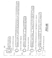
- an initialization step 100 is called, in which the receiving system represented in Figure 4A is initialized, in particular, the calculation values are all reset for example.
- Step 100 is followed, after initialization is completed, of a channel polling step 101 and a sliding correlation synchronization search, as previously mentioned in the description.
- This step is carried out, as described previously in the description, from the pseudo-random codes used to each of the users, and, of course, from the position of the pulses received, transmitted and therefore received, taking into account the pseudo-random code. supra.
- the appearance of a main correlation peak makes it possible to synchronize the receiver system which is the subject of the invention, as represented in FIG. Figure 4A on the transmitter, detecting and marking the main path, following detection of the position of each main pulse. In this situation, the secondary correlation peaks, revealing the existence of secondary propagation paths, are then detected and the value of the correlation coefficient Global GCC and GAC Global Acquisition Correlation Coefficient are then updated accordingly.
- the channel exploration and tracking module 1 0 then makes it possible to encrypt the paths to be processed, to assign them, possibly, a weighting coefficient, in the same way as in the case of the devices of the prior art, and note the respective propagation time as mentioned previously in the description for successive pulses.
- the selection of the paths can be carried out either by retaining the N strongest paths or the first N paths or, where appropriate, a compromise between the two.
- the step 101 is followed by a single-path reception step 102 during which the selection of the paths can be performed.
- a particularly advantageous selection process may consist in processing the first arrived path, then adding the following paths one by one until the taking into account of additional paths no longer increases the signal ratio. to global noise.
- the single-path reception is acquired, that is to say reception of the main paths, and the selection of the propagation paths of the secondary pulses is also established, the aforementioned selection is then exploitable.
- one of the correlators thus operates in reception, while the correlator 1 12 of the acquisition correlation and tracking 1 1 1 operates by sliding correlation in order to keep the image of the transmission channel up to date.
- This operation is carried out at step 103 of the Figure 4B , the reception then being performed in multi-path.
- the channel exploration and tracking module makes it possible to detect the appearance or disappearance of propagation paths, as well as to continue the aforementioned paths.
- the continuation of the paths can be carried out according to the criterion of energy or signal-to-noise ratio mentioned previously in the description.
- the channel exploration and tracking module 1 0 thus makes it possible to ensure a dynamic processing of the paths, to assign and modify the weighting coefficients when they are used and to change the list of paths processed, the path list signal LT being air if modified for updating.
- the operation 103 is followed by a multi-path reception operation 104 consisting in updating the selection of the paths, that is to say of the list of the paths LT.
- the return arrow from step 104 to step 103, on the Figure 4B illustrates the continuous nature of multi-path reception and, of course, channel scanning and updating of the LT path list.
- this weighting operation can be implemented at the level of the elementary correlation pattern generator 2 1 of the single global correlation path 2, at each elementary pattern can then be applied, at the aforementioned generator 2 1 , an amplitude proportional to the weighting coefficient of the associated path.
- a device for controlling the amplitude of the pattern shown at 2a in the drawing, can be added if necessary.
- the number of correlation channels can be substantially reduced to two, a single correlation channel ensuring the reception properly. said and a global correlation acquisition path, as described above.
- the method and the system that are the subject of the invention appear particularly advantageous insofar as the number of paths processed is adaptive, the adaptive character resulting from the possibility of choosing and adapting the number of reception paths processed during operation. .
- a receiver according to the object of the present invention is able to modify its characteristics dynamically and therefore to adapt ideally to the operating conditions dictated by the qualities of the parameters, such as quality of connection, constraints of autonomy and variability of the transmission channel.
- the number of paths processed is not limited by hardware execution contingencies but, on the contrary, by signal-to-noise or specific energy value value criteria, for example.
Landscapes
- Engineering & Computer Science (AREA)
- Computer Networks & Wireless Communication (AREA)
- Signal Processing (AREA)
- Radar Systems Or Details Thereof (AREA)
- Synchronisation In Digital Transmission Systems (AREA)
- Cable Transmission Systems, Equalization Of Radio And Reduction Of Echo (AREA)
- Circuits Of Receivers In General (AREA)
- Monitoring And Testing Of Transmission In General (AREA)
Abstract
Description
L'invention concerne un procédé et un système de réception d'un signal ultra-large bande, à nombre de trajets de propagation auto-adaptatif.The invention relates to a method and a system for receiving an ultra-broadband signal with a number of self-adaptive propagation paths.
La technique des communications radio en signal ultra-large bande, encore désigné UWB en langage anglo-saxon, n'utilise pas de fréquence porteuse. Au lieu de moduler un signal ou onde porteuse support, l'information à transmettre est émise directement en bande de base, en utilisant des impulsions support de très courte durée, moins d'une nanoseconde, et donc d'une très grande largeur de bande, plusieurs GHz.The technique of radio communications in ultra-wide band signal, also called UWB in English language, does not use a carrier frequency. Instead of modulating a signal or carrier carrier wave, the information to be transmitted is transmitted directly in baseband, using very short carrier pulses, less than a nanosecond, and therefore a very large bandwidth , several GHz.
Ces impulsions étant émises à faible puissance, la densité spectrale de puissance du signal émis est, en conséquence très faible.Since these pulses are emitted at low power, the spectral power density of the emitted signal is consequently very low.
Ainsi, un signal UWB n'est pas un signal continu mais, au contraire, un train d'impulsions très brèves et de très faible rapport cyclique.Thus, a UWB signal is not a continuous signal but, on the contrary, a train of very short pulses and very low duty cycle.
L'accès multiple à la transmission par un tel signal est réalisé, habituellement, en faisant des sauts temporels (Time Hopping) régis par une séquence pseudo aléatoire. Le signal peut être modulé en amplitude, par le facteur de forme ou même le retard des impulsions successives.The multiple access to the transmission by such a signal is realized, usually, making time hops (Time Hopping) governed by a pseudo random sequence. The signal can be modulated in amplitude, by the form factor or even the delay of the successive pulses.
En rupture avec les concepts des techniques de base utilisant une onde porteuse, les techniques d'émission et de réception de signaux UWB sont des techniques sui generis, se rapprochant des techniques de détection des signaux à étalement de spectre.In contrast to basic carrier technology concepts, UWB signal transmission and reception techniques are sui generis techniques, approaching spread spectrum signal detection techniques.
En particulier, les récepteurs de signaux UWB "en râteau" sont conçus pour fonctionner dans des environnements perturbés, où la topologie du lieu d'utilisation crée des canaux de transmission complexes, variables ou lentement variables, en raison de nombreux trajets de propagation secondaires multiples, et interdit, en pratique, l'existence d'un trajet de propagation en vision directe.In particular, UWB "rake" signal receivers are designed to operate in disturbed environments, where the location topology creates complex, variable or slowly varying transmission channels due to multiple multiple secondary propagation paths. and, in practice, prohibits the existence of a propagation path in direct vision.
Ainsi, dans ce but, les récepteurs de signaux UWB connus de l'état de la technique présentent habituellement une structure dite "en râteau" inspirée de celles utilisées pour les récepteurs de signaux à étalement de spectre.Thus, for this purpose, UWB signal receivers known from the state of the art usually have a so-called "rake" structure inspired by those used for spread spectrum signal receivers.
Un tel récepteur est décrit dans le document
Ainsi que représenté en
Pour assurer le bon fonctionnement du récepteur, il est nécessaire d'affecter l'une des branches de réception à la recherche de nouveaux trajets de propagation d'impulsions secondaires et/ou principale. Pour un récepteur UWB en râteau à N "doigts" ou trajets, il est donc nécessaire de prévoir N+1 branches de réception.To ensure the proper functioning of the receiver, it is necessary to assign one of the reception branches in search of new secondary and / or main pulse propagation paths. For a UWB rake receiver with N "fingers" or paths, it is therefore necessary to provide N + 1 receiving branches.
Ainsi que représenté en outre en
Lorsque le récepteur UWB en râteau est synchronisé, la logique de contrôle du récepteur déclenche la génération de motif correspondant aux instants d'arrivée d'une impulsion. Ce dernier engendre un motif de corrélation conçu pour présenter une forte valeur d'intercorrélation avec l'impulsion reçue et une valeur d'intercorrélation nulle en présence de bruit blanc. Une valeur d'intercorrélation intermédiaire importante indique la présence d'une impulsion directe ou secondaire.When the UWB rake receiver is synchronized, the control logic of the receiver triggers the pattern generation corresponding to the arrival times of a pulse. The latter generates a correlation pattern designed to have a high intercorrelation value with the received pulse and a zero intercorrelation value in the presence of white noise. A large intermediate intercorrelation value indicates the presence of a direct or secondary pulse.
La
Le motif de corrélation est conçu pour que la valeur du coefficient d'intercorrélation soit positif en présence d'une impulsion non décalée (A), correspondant à la transmission d'une valeur zéro mais négative en présence d'une impulsion décalée (B), correspondant à la transmission d'une valeur un, et nul en l'absence d'impulsions. Le motif de corrélation est ainsi symétrique par rapport à un centre de asymétrie.The correlation pattern is designed so that the value of the cross-correlation coefficient is positive in the presence of an unshifted pulse (A), corresponding to the transmission of a zero but negative value in the presence of a shifted pulse (B) , corresponding to the transmission of a value one, and zero in the absence of pulses. The correlation pattern is thus symmetrical with respect to a center of asymmetry.
Toutefois, un symbole étant le plus souvent codé sur plusieurs impulsions, il est nécessaire d'intégrer les valeurs du coefficient d'intercorrélation obtenues pour chaque impulsion relative à un même symbole et ainsi obtenir une valeur de coefficient de corrélation globale du symbole. Cette valeur est transmise à la logique de contrôle du récepteur pour y être interprétée en fonction de la méthode de codage utilisée et retrouver ainsi le symbole transmis.However, since a symbol is most often coded over several pulses, it is necessary to integrate the values of the coefficient intercorrelation obtained for each pulse relative to the same symbol and thus obtain a global correlation coefficient value of the symbol. This value is transmitted to the control logic of the receiver to be interpreted according to the coding method used and thus find the transmitted symbol.
Un autre exemple concret illustré dans le cas d'une modulation PPM avec deux utilisateurs simultanés disposant chacun d'une séquence pseudo aleatoire est représenté en
L'emplacement de cette impulsion dans la trame Tf est fixé par rapport à des intervalles élémentaires de trame par la valeur de la séquence pseudo aléatoire propre à chaque utilisateur. Enfin, chaque impulsion est décalée d'un intervalle de temps δ par rapport au début de chaque intervalle élémentaire de trame lorsque la transmission binaire représentée est celle de la valeur 1 au lieu de la valeur 0, en l'absence de décalage.The location of this pulse in the frame T f is fixed with respect to elementary frame intervals by the value of the pseudo-random sequence specific to each user. Finally, each pulse is shifted by a time interval δ with respect to the beginning of each elementary frame interval when the bit transmission represented is that of the
Les récepteurs UWB en râteau précités impliquent un surcoût important en complexité, car chaque doigt supplémentaire suppose l'intégration d'une branche de réception supplémentaire. En conséquence, il existe une limite assez draconienne au nombre de doigts que peut présenter un récepteur de ce type, eu égard aux contraintes d'intégration, d'encombrement, de coût et de consommation.The UWB rake receivers mentioned above imply a significant extra cost in complexity, because each additional finger supposes the integration of an additional reception branch. Consequently, there is a rather draconian limit to the number of fingers that a receiver of this type can have, given the constraints of integration, congestion, cost and consumption.
En pratique, il est rare de pouvoir disposer d'un récepteur UWB en râteau présentant plus de quatre doigts, soit cinq branches de réception effectives.In practice, it is rare to have a rake UWB receiver having more than four fingers, or five effective reception branches.
De tels récepteurs s'avèrent donc cantonnés à des applications haut de gamme, pour lesquels le critère de coût est secondaire vis-à-vis de celui des performances globales de qualité de la liaison.Such receivers are therefore confined to high-end applications, for which the cost criterion is secondary vis-à-vis that of the overall quality performance of the link.
Des solutions de récepteur UWB "en râteau" tout numérique ont été envisagées, dans lesquelles le signal reçu est directement numérisé en sortie d'antenne. Bien que, en raison du traitement purement logiciel du signal numérisé précité, la structure de tels récepteurs ne soit plus en rapport avec l'architecture en râteau traditionnelle, de telles solutions ne sont pas viables actuellement car les convertisseurs analogiques-numériques actuels ne sont pas adaptés à une telle utilisation, et les traitements numériques à effectuer sur les signaux numériques précités ne peuvent être exécutés en temps réel par les processeurs de signaux numériques actuels.UWB all-digital rake receiver solutions have been envisaged, in which the received signal is directly digitized at the antenna output. Although, because of purely signal processing software digitized supra, the structure of such receivers is no longer in connection with the traditional rake architecture, such solutions are not viable at present because the current analog-digital converters are not suitable for such use, and digital processing to perform on the aforementioned digital signals can not be performed in real time by the current digital signal processors.
La présente invention a pour but de remédier à l'ensemble des inconvénients de la technique antérieure de mise en oeuvre des récepteurs d'un signal UWB en râteau:
- En particulier, un objet de la présente invention est la mise en oeuvre d'un procédé et d'un système de réception d'un signal ultra-large bande UWB dont l'architecture matérielle est notablement simplifiée vis-à-vis de celle des récepteurs UWB en râteau de l'art antérieur.
- In particular, an object of the present invention is the implementation of a method and a system for receiving an ultra-broadband UWB signal whose hardware architecture is significantly simplified with respect to that of UWB rake receivers of the prior art.
Un autre objet de la présente invention est la mise en oeuvre d'un procédé et d'un système de réception d'un signal UWB grâce auxquels les coûts de mise en oeuvre sont sensiblement réduits, en raison de la simplification précitée.Another object of the present invention is the implementation of a method and a system for receiving a UWB signal by means of which the implementation costs are substantially reduced, because of the aforementioned simplification.
Un autre objet de la présente invention est la mise en oeuvre d'un procédé et d'un système de réception d'un signal ultra-large bande grâce auquel, malgré la simplification significative de la structure mise en oeuvre, une amélioration de la qualité de liaison et des performances globales est obtenue de manière significative en raison de l'absence de limitation matérielle du nombre de trajets de propagation principal et secondaires effectivement traités.Another object of the present invention is the implementation of a method and a system for receiving an ultra-broadband signal by which, despite the significant simplification of the structure used, an improvement in the quality Linkage and overall performance is significantly achieved due to the lack of hardware limitation in the number of main and secondary propagation paths actually handled.
Un autre objet de la présente invention est, enfin, en raison de l'absence de limitation matérielle du nombre de trajets principal et secondaires effectivement précités, la mise en oeuvre d'un procédé et d'un système de réception d'un signal ultra-large bande à nombre de trajets de propagation effectivement traité auto-adaptatif, ce qui permet d'optimiser la qualité de la liaison radio entre émetteur et récepteur, même en présence d'un canal de transmission issu d'un environnement sévère variable.Another object of the present invention is, finally, because of the absence of hardware limitation of the number of main and secondary paths actually mentioned above, the implementation of a method and a system for receiving an ultra signal. a large band with a number of propagation paths actually treated as auto-adaptive, which makes it possible to optimize the quality of the radio link between transmitter and receiver, even in the presence of a transmission channel originating from a variable severe environment.
Le procédé et le système de réception UWB, objets de la présente invention, trouvent application à la liaison radio d'appareils domestiques ou professionnels de tout type, en particulier en environnement correspondant à un canal de transmission par voie hertzienne sensiblement perturbé ou variable.The method and the UWB reception system, objects of the present invention, find application to the radio link of domestic appliances or professionals of any type, especially in environment corresponding to a transmission channel over the air path that is substantially disturbed or variable.
Ils seront mieux compris à la lecture de la description et à l'observation des figures ci-après dans lesquelles, outre les
- la
figure 2 représente, à titre illustratif, un organigramme des étapes essentielles permettant la mise en oeuvre du procédé objet de la présente invention ; - les
figures 3A, 3C et 3D représentent, à titre de pur exemple illustratif, des chronogrammes de détection de symboles transmis selon des trajets multiples, à partir d un motif de corrélation composite, conformément au procédé objet de la présente invention, dans le cas où la transmission est effectuée à titre d'exemple non limitatif en mode 2-PPM, les impulsions directes et secondaires, se propageant selon un trajet direct respectivement secondaire, étant prises en compte :
- la
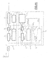
figure 4A représente, à titre d'exemple purement illustratif, le schéma fonctionnel sous forme de schémas blocs, d'un système de réception d'un signal UWB à nombre de trajets de propagation auto-adaptatif, conforme à l'objet de la présente invention :
- la
figure 4B représente, à titre illustratif, un organigramme de mise en oeuvre du fonctionnement du système objet de l'invention, tel que représenté enfigure 4A .
- the
figure 2 represents, by way of illustration, a flowchart of the essential steps that make it possible to implement the method that is the subject of the present invention; - the
Figures 3A, 3C and 3D represent, as a purely illustrative example, multipath-transmitted symbol detection timing diagrams from a composite correlation pattern, in accordance with the method of the present invention, in the case where the transmission is carried out as a non-limiting example in 2-PPM mode, the direct and secondary pulses, propagating in a direct or respectively secondary path, being taken into account:
- the
Figure 4A represents, by way of purely illustrative example, the block schematic block diagram of a UWB signal reception system with a number of self-adaptive propagation paths, in accordance with the object of the present invention:
- the
Figure 4B represents, by way of illustration, a flowchart for implementing the operation of the system which is the subject of the invention, as represented in FIG.Figure 4A .
Une description plus détaillée du procédé et du système de réception d'un signal ultra-large bande, conforme à l'objet de la présente invention, sera maintenant donnée en liaison avec la
D'une manière générale, on rappelle que le processus de transmission du signal ultra-large bande correspond à celui décrit précédemment en liaison avec les
On comprend, en particulier, dans ces conditions, que chaque impulsion directe correspond à un temps de propagation le plus court, chaque impulsion secondaire successive distincte, associée à l'impulsion directe précitée, étant alors décalée successivement dans le temps par rapport à l'instant de réception, de l'impulsion directe à laquelle ces dernières sont associées.It is understood, in particular, under these conditions, that each direct pulse corresponds to a shortest propagation time, each distinct successive secondary pulse, associated with the aforementioned direct pulse, then being successively shifted in time with respect to the moment of reception, of the direct impulse to which these latter are associated.
Les trajets de propagation directe et secondaire ne préjugent aucunement du nombre de réflexions de l'impulsion correspondante se propageant sur ces trajets Toutefois, les impulsions secondaires successives distinctes sont engendrées par un nombre sensiblement croissant de réflexions, chaque réflexion étant le siège d'une atténuation, et les impulsions secondaires successives distinctes sont considérées présenter une amplitude ou une énergie sensiblement décroissante en fonction de leur rang de réception.The direct and secondary propagation paths in no way prejudge the number of reflections of the corresponding pulse propagating on these paths. However, the successive distinct secondary pulses are generated by a substantially increasing number of reflections, each reflection being the seat of attenuation. , and the successive distinct secondary pulses are considered to have a substantially decreasing amplitude or energy as a function of their reception rank.
En conséquence, on considère la transmission d'impulsions IDij, ces impulsions correspondant, par exemple, aux impulsions émises, telles que représentées en
A titre d'exempte non limitatif et de simplification de la description, on considère le code pseudo-aléatoire affecté à chacun des utilisateurs i=1. i=2 de la
Le décalage temporel δ est le même que dans le cas de la
En référence à la
Dans ces conditions, la suite d'impulsions directes et d'impulsions secondaires associées est notée : ![]()
![]()
Dans cette notation, i et j représentent la référence utilisateur, respectivement la référence de trame dans le temps symbole Ts et k représente le rang de l'impulsion reçue, impulsion directe et/ou impulsion secondaire.In this notation, i and j represent the user reference, respectively the frame reference in the symbol time T s and k represents the rank of the received pulse, direct pulse and / or secondary pulse.
Par convention, on indique que le rang de l'impulsion directe, dans chaque trame Tf, est arbitrairement pris égal à 0, soit k=0, les impulsions secondaires distinctes successives présentant un rang k=1 à N par exemple.By convention, it is indicated that the rank of the direct pulse, in each frame T f , is arbitrarily taken equal to 0, ie k = 0, the successive distinct secondary pulses having a rank k = 1 to N for example.
L'étape A de réception est alors suivie d'une étape B consistant à engendrer, par calcul, un motif de corrélation composite constitué par une suite de motifs de corrélation élémentaires.The receiving step A is then followed by a step B consisting of generating, by calculation, a composite correlation pattern constituted by a sequence of elementary correlation patterns.
D'une manière générale, on indique que chaque motif de corrélation élémentaire correspond, dans l'exemple non limitatif de la modulation 2-PPM, au signal dit de gabarit représenté en
D'une manière plus spécifique, on indique que la suite de motifs de corrélation élémentaires comprend un premier motif de corrélation élémentaire associé à chaque impulsion directe, c'est-à-dire à toute impulsion correspondait en position dans chaque trame Tf à la position donnée par le code pseudo-aléatoire affecté à chaque utilisateur et, bien entendu, des motifs de corrélation élémentaires successifs associés chacun à une impulsion secondaire successive de rang k, k ∈ [1,N].More specifically, it is indicated that the sequence of elementary correlation patterns comprises a first elementary correlation pattern associated with each forward pulse, that is, any pulse corresponding in position in each frame T f to the position given by the pseudo-random code assigned to each user and, of course, successive elementary correlation patterns each associated with a successive secondary pulse of rank k, k ∈ [1, N].
Bien entendu, les motifs de corrélation élémentaires successifs, associées à chaque impulsion secondaire, sont décalés en temps par rapport au premier motif de corrélation élémentaires associé à l'impulsion directe d'une valeur correspondant à la différence de temps de propagation entre, d'une part, le temps de propagation de l'impulsion directe, de rang k=0, sur le trajet de propagation directe, et, d'autre part, le temps de propagation de l'impulsion secondaire associée, de ring successive k ∈ [1,N] sur le trajet de propagation secondaire correspondant.Of course, the successive elementary correlation patterns, associated with each secondary pulse, are offset in time with respect to the first elementary correlation pattern associated with the direct pulse of a value corresponding to the difference in propagation time between, d on the one hand, the propagation time of the direct pulse, of rank k = 0, on the direct propagation path, and, on the other hand, the propagation time of the associated secondary pulse, of successive ring k ∈ [ 1, N] on the corresponding secondary propagation path.
Pour engendrer le motif de corrélation composite précité, l'on procède à titre d'exemple non limitatif, à la détection par corrélation glissante de l'ensemble des impulsions directes respectivement secondaires reçues sur un temps symbole. On indique, en effet, que le calcul ainsi effectué sur un temps symbole peut alors être utilisé pour le temps symbole suivant, en raison du fait que, sur un temps symbole, le cas échéant sur deux temps symboles consécutifs, le canal de transmission est considéré comme sensiblement invariable. Le processus de mise en oeuvre et de calcul du motif de corrélation composite sera décrit de manière plus détaillée dans la description.To generate the abovementioned composite correlation pattern, the sliding secondary correlation detection of the set of direct or secondary pulses received over a symbol time is carried out by way of non-limiting example. It is indicated, in fact, that the calculation thus carried out on a symbol time can then be used for the next symbol time, due to the fact that, on a symbol time, where appropriate on two consecutive symbol times, the transmission channel is considered substantially invariable. The process of implementing and calculating the composite correlation pattern will be described in more detail in the description.
L'étape B est alors suivie d'une étape C consistant à calculer la valeur du coefficient d'intercorrélation globaleStep B is then followed by a step C of calculating the value of the global intercorrelation coefficient
GCC désigne la valeur du coefficient d'intercorrélation globale obtenuGCC means the value of the overall cross-correlation coefficient obtained
On indique que la valeur du coefficient d'intercorrélation globale GCC est ainsi constitué par la somme des coefficients d'intercorrélation de chacune des impulsions directes et secondaires obtenues pour chacune des impulsions modulées émises pour le même symbole et représente une valeurs de corrélation globale du symbole transmis pour chaque utilisateur.It is indicated that the value of the global intercorrelation coefficient GCC is thus constituted by the sum of the intercorrelation coefficients of each of the direct and secondary pulses obtained for each of the modulated pulses transmitted for the same symbol and represents a global correlation value of the symbol. transmitted for each user.
L'opération de calcul du coefficient d'intercorrélation globale comprend, ainsi, en référence à l'étape C de la
Une illustration de la mise en oeuvre des étapes A, B et C représentées en
Sur la
Les impulsions directes de rang k=0 engendrées pour les utilisateurs 1 et 2 sont représentées différemment par hachures et points, les impulsions secondaires de rang k>1 étant limitées à k=3 afin de ne pas surcharger le dessin.The direct pulses of rank k = 0 generated for the
On comprend, en particulier, que la position des impulsions secondaires, telle que ID111 à ID113 peut être quelconque par rapport à toute impulsion directe k=0 ultérieur.In particular, it will be understood that the position of the secondary pulses, such as ID 111 to ID 113, may be arbitrary with respect to any subsequent forward pulse k = 0.
Dans ces conditions, le décalage temporel θ11, θ12, θ13, respectivement θ21, θ22, θ23 de chaque impulsion secondaire associée à l'impulsion directe correspondante se répète sur chaque intervalle trame successif Tf sans changement en référence à la convention précédemment mentionnée.Under these conditions, the time shift θ 11 , θ 12 , θ 13 , respectively θ 21 , θ 22 , θ 23 of each secondary pulse associated with the corresponding direct pulse is repeated on each successive frame interval T f without any change with reference to the previously mentioned convention.
Ainsi, le motif de corrélation composite, peut alors être engendré de la manière ci-après :
- verrouillage de chaque motif de corrélation élémentaire sur chaque impulsion directe de rang k=0 ;
- calcul du coefficient d'intercorrélation de motifs de corrélation élémentaires successifs engendrés par exemple à des intervalles de temps correspondant à la résolution temporelle d'un gabarit constitutif de chaque motif de corrélation élémentaire, tel que représenté en
figure 1C ; - sélection des seuls motifs de corrélation élémentaires successifs dont le produit d'intercorrélation est supérieur à une valeur de seuil, par exemple, pour constituer le motif de corrélation composite.
- locking each elementary correlation pattern on each direct pulse of rank k = 0;
- calculating the coefficient of intercorrelation of successive elementary correlation patterns generated for example at time intervals corresponding to the temporal resolution of a constituent template of each elementary correlation pattern, as represented in FIG.
figure 1C ; - selecting only successive elementary correlation patterns whose intercorrelation product is greater than a threshold value, for example, to form the composite correlation pattern.
On comprend, dans ces conditions, que le motif de corrélation composite précité est constitué sensiblement par des motifs de corrélation élémentaires engendrés à l'instant d'apparition non seulement des impulsions directes de rang k=0, mais des impulsions secondaires de rang k>1 pour lesquelles le coefficient d'intercorrélation, avec un motif de corrélation élémentaire, est supérieur à la valeur de seuil précitée.It is understood, under these conditions, that the above-mentioned composite correlation pattern consists essentially of elementary correlation patterns generated at the instant of appearance not only of direct pulses of rank k = 0, but of secondary pulses of rank k> 1 for which the intercorrelation coefficient, with an elementary correlation pattern, is greater than the aforementioned threshold value.
Le processus de calcul de la valeur de coefficient d'intercorrélation globale GCC est alors effectué, ainsi que représenté en
D'une manière générale, on indique que, alors que la synchronisation du motif de corrélation composite est effectuée sensiblement sur un temps symbole, à partir des impulsions directes et, bien entendu, des codes pseudo-aléatoires attribués à chacun des utilisateurs, la discrimination du rang des impulsions secondaires n'est pas indispensable, seule la position de ces impulsions dans un temps symbole Ts étant prise finalement en considération.In general, it is indicated that, while the synchronization of the composite correlation pattern is performed substantially on a symbol time, from the direct pulses and, of course, the pseudo-random codes attributed to each of the users, the discrimination the rank of the secondary pulses is not essential, only the position of these pulses in a symbol time T s being finally taken into consideration.
Le procédé objet de la présente invention apparaît, ainsi, particulièrement remarquable en ce que le nombre d'impulsions finalement retenues pour assurer l'opération de calcul du motif de corrélation composite, puis de la valeur du coefficient d'intercorrélation globale, peut être élevé et facilement choisi, par exemple, à un nombre de 10 impulsions secondaires pour chaque impulsion directe en fonction des caractéristiques d'utilisation et de mise en oeuvre du procédé objet de l'invention,The method that is the subject of the present invention thus appears to be particularly remarkable in that the number of pulses finally retained for performing the computation operation of the composite correlation pattern and then the value of the overall intercorrelation coefficient can be high. and easily selected, for example, at a number of 10 secondary pulses for each direct pulse according to the characteristics of use and implementation of the method which is the subject of the invention,
En particulier, le choix du nombre des impulsions retenues peut être guidé par des considérations relatives soit au niveau d'amplitude et/ou d'énergie des impulsions secondaires ou, de manière plus simple, au nombre éffectif d'impulsions retenues.In particular, the choice of the number of pulses retained may be guided by considerations relating either to the amplitude and / or energy level of the secondary pulses or, more simply, to the number of pulses retained.
Ainsi, pour un ensemble dénombrable d'impulsions directes et secondaires, compte tenu de la discrimination temporelle de deux impulsions successives, le procédé objet de l'invention peut consister à retenir les N premiers trajets, les N premiers trajets précités comportant le trajet direct de rang k=0, correspondant à un temps de propagation de l'impulsion modulée associée le plus faible, et N-1 trajets secondaires correspondant chacun à un temps de propagation d'une impulsion secondaire successivement croissante.Thus, for a countable set of direct and secondary pulses, taking into account the temporal discrimination of two successive pulses, the method which is the subject of the invention can consist in retaining the first N paths, the first N aforementioned paths comprising the direct path of rank k = 0, corresponding to a propagation time of the weakest associated modulated pulse, and N-1 secondary paths each corresponding to a propagation time of a successively increasing secondary pulse.
Dans cette solution on indique que le nombre d'impulsions secondaires retenues peut consister à discriminer toute impulsion directe d'une même trame et à retenir les impulsions secondaires comprises entre deux impulsions directes successives ou même trois impulsions directes successives. Le nombre d'impulsions secondaires ainsi retenues permet de définir et de retenir les N premiers trajets.In this solution it is indicated that the number of secondary pulses retained can consist in discriminating any direct pulse of the same frame and in retaining the secondary pulses between two successive direct pulses or even three successive direct pulses. The number of secondary pulses thus retained makes it possible to define and retain the first N paths.
Une autre possibilité pour le choix du nombre d'impulsions secondaires peut consister, pour l'ensemble dénombrable d'impulsions directes et d'impulsions secondaires considérées, à retenir N trajets pour lesquels l'amplitude ou l'énergie de l'impulsion directe respectivement des impulsions secondaires est maximale.Another possibility for the choice of the number of secondary pulses may consist, for the countable set of direct pulses and secondary pulses considered, to retain N paths for which the amplitude or the energy of the direct pulse respectively secondary pulses are maximum.
Un tel mode opératoire consiste, bien entendu, outre la discrimination des amplitudes ou énergie des impulsions directes de rang k=0 considérées comme maximale, une discrimination des impulsions secondaires se on leur amplitude et/ou leur énergie de façon à retenir les N impulsions d'amplitude et/ou d'énergie la meilleure.Such a procedure consists, of course, in addition to the discrimination of the amplitudes or energy of the direct pulses of rank k = 0 considered as maximum, a discrimination of the secondary pulses is their amplitude and / or their energy so as to retain the N pulses d amplitude and / or energy the best.
On comprend, toutefois, que la discrimination par le seul nombre N d'impulsions secondaires associées à une impulsion directe est susceptible de se révéler moins performante, du point de vue de la mise en oeuvre du procédé objet de l'invention, que la discrimination par un critère d'amplitude et/ou d'énergie des impulsions précitées.It is understood, however, that the discrimination by the single number N of secondary pulses associated with a direct pulse is likely to be less efficient, from the point of view of the implementation of the method which is the subject of the invention, than the discrimination by a criterion of amplitude and / or energy of the aforementioned pulses.
En tout état de cause, le nombre N de trajets retenus peut être adapté soit selon un critère de sélection des N premiers trajets pour exécution d'un traitement plus rapide soit, au contraire, selon un critère de sélection de N trajets correspondant à une amplitude et/ou une énergie maximale de l'impulsion directe et des impulsions secondaires en fonction des conditions de propagation. Un tel mode opératoire permet ainsi d'optimiser la qualité de la liaison par signal ultra-large bande.In any case, the number N of paths selected may be adapted either according to a selection criterion of the first N paths for execution of a faster processing or, on the contrary, according to a selection criterion of N paths corresponding to an amplitude. and / or a maximum energy of the direct pulse and secondary pulses depending on the propagation conditions. Such a mode of operation thus makes it possible to optimize the quality of the ultra-wideband signal link.
En ce qui concerne l'opération de calcul du motif de corrélation composite on indique que ce processus consiste, en fait, à établir par corrélation sur au moins un temps symbole Ts, une image du canal de transmission en termes d'impulsions directes et d'impulsions secondaires de temps de propagation et de différence de temps de propagation entre impulsions directes et impulsions secondaires successives, puis à mettre à jour, par corrélation glissante, l'image du canal de transmission pour actualiser l'apparition et la disparition de trajets de propagation secondaires, le cas échéant de trajets de propagation directs, et établir, sur au moins un temps symboles, le motif de corrélation composite comme image actualisée du canal de transmission.With regard to the calculation operation of the composite correlation pattern, it is indicated that this process consists, in fact, of establishing by correlation on at least one symbol time T s , an image of the transmission channel in terms of direct pulses and of secondary pulses of propagation time and difference in propagation time between direct pulses and successive secondary pulses, then to update, by sliding correlation, the image of the transmission channel to update the appearance and disappearance of paths of secondary propagation, the case appropriate direct propagation paths, and establish, over at least one symbol time, the composite correlation pattern as the updated image of the transmission channel.
Une description plus détaillée d'un système de réception d'un signal ult-a-large bande représentatif de symboles objet de la présente invention sera maintenant donnée en liaison avec les
Ainsi que représentée sur la
A titre d'exemple non limitatif, les circuits de réception communs comportent une antenne An et un amplificateur à faible bruit LNA constituant amplificateur d'antenne:
- Ils comportent, en outre,
une voie 1 d'acquisition et d'actualisation sur au moins un temps symbole Ts d'une image du canal de transmission en termes d'impulsions directes et d'impulsions secondaires, de temps de propagation et de différence de temps de propagation entre impulsions directes et impulsions secondaires successives.
- They furthermore comprise a
channel 1 for acquisition and updating over at least one symbol time T s of an image of the transmission channel in terms of direct pulses and secondary pulses, of propagation time and of difference in propagation time between direct pulses and successive secondary pulses.
Ainsi que mentionné précédemment relativement au procédé objet de l'invention, la voie d'acquisition et d'actualisation 1 permet, par corrélation glissante, d'assurer une actualisation de l'apparition et de la disparition de trajets de propagation secondaires, ainsi que du trajet de propagation principal et bien entendu, d'établir sur au moins un temps symbole le motif de corrélation composite précédemment mentionné dans la description.As mentioned above with respect to the method that is the subject of the invention, the acquisition and updating
Ainsi que représenté sur la
A titre d'exemple non limitatif, on indique que le signal de liste de trajets peut correspondre à la désignation des instants, sur le temps symbole, auxquels chaque motif de corrélation élémentaire doit être engendré successivement pour réaliser le motif de corrélation composite précédemment cité.By way of nonlimiting example, it is indicated that the path list signal can correspond to the designation of the instants, on the symbol time, to which each elementary correlation pattern must be successively generated to achieve the aforementioned composite correlation pattern.
De même que le motif de corrélation composite, on indique que les instants désignés par le signal de liste de trajets LT sont, bien entendu, décalés en temps par rapport à l'instant du premier motif de corrélation élémentaire associé à chaque impulsion directe de la différence de temps de propagation entre le temps de propagation de l'impulsion directe sur le trajet de propagation directe et le temps de propagation de l'impulsion secondaire associée se propageant sur le trajet de propagation secondaire correspondant.As well as the composite correlation pattern, it is indicated that the instants designated by the path list signal LT are, of course, offset in time with respect to the instant of the first elementary correlation pattern associated with each direct pulse of the difference in propagation time between the propagation time of the direct pulse on the direct propagation path and the propagation time of the associated secondary pulse propagating on the corresponding secondary propagation path.
En outre, le système objet de la présente invention comporte une voie 2 de corrélation unique recevant le signal de liste de trajets de propagation directs et secondaires LT, la voie de corrélation unique 2 permettant de calculer la valeur du coefficient d'intercorrélation global GCCIn addition, the system which is the subject of the present invention comprises a single correlation channel 2 receiving the direct and secondary propagation path list signal LT, the unique correlation path 2 making it possible to calculate the value of the overall intercorrelation coefficient GCC.
Une description plus détaillée de la voie d'acquisition et d'actualisation 1 sera maintenant donnée ci-après en référence à la même
Selon un premier mode de réalisation, la voie d'acquisition et d'actualisation 1 précitée comporte une voie de corrélation globale d'acquisition et ce poursuite, notée 11 recevant la suite des impulsions successives délivrées par les Circuits de réception communs et délivrant une valeur de coefficient de corrélation globale d'acquisition, notée GAC1.According to a first embodiment, the aforementioned acquisition and updating
D'une manière plus spécifique, on indique que, de manière semblable aux dispositifs de l'art antérieur, tel que représenté en
La voie d'acquisition et d'actualisation 1 comporte, en outre, un module 10 d'exploration et de poursuite de canal, lequel reçoit la valeur de coefficient de corrélation globale d'acquisition GAC1 délivré par la voie de corrélation globale d'acquisition et de poursuite 11 précédemment citée, ainsi que la valeur du coefficient d'intercorrélation globale GCC délivrée par la voie 2 de corrélation unique.The route of acquisition and updating 1 further comprises a
Le module 10 d'exploration et de poursuite de canal délivre le signal de liste de trajets de propagation directs et secondaires LT précédemment décrite dans la description relativement à la mise en oeuvre du procédé objet de l'invention, ainsi qu'un signal de synchronisation ST1 sur le temps symbole au générateur de motifs élémentaires de synchronisation 111 constitutif de la voie d'acquisition et d'actualisation 11.
Dans ces conditions, le générateur de motifs élémentaires de synchronisation 111 délivre, après acquisition de l'image du canal par corrélation glissante, un ensemble de motifs de synchronisation élémentaires SEM1 formant un motif de corrélation d'acquisition, lequel correspond sensiblement à l'existence d'un motif de corrélation élémentaire engendré à l'instant d'existence prévisible de chaque impulsion directe ou d'impulsions secondaires associées à celle-ci, en l'absence de variabilité significative du canal de transmission.Under these conditions, the generator of elementary synchronization patterns 11 delivers, after acquisition of the image of the sliding correlation channel, a set of elementary synchronization patterns SEM 1 forming an acquisition correlation pattern, which corresponds substantially to the existence of an elementary correlation pattern generated at the predictable moment of existence of each direct pulse or of secondary pulses associated therewith, in the absence of significant variability of the transmission channel.
Pour une description plus détaillée d'un processus d'acquisition et de poursuite par corrélation glissante, on pourra utilement se reporter à l'article intitulé "Rapid Acquisition for Ultra-Wideband Localizers" publié par Robert Fleming, Cherie Kushner, Gary Roberts, Uday Nandiwada, AEther Wire & Location, Inc. par exemple. L'article précité est disponible sur le site Internet http://www.aetherwire.com.For a more detailed description of a slippery correlation acquisition and tracking process, reference may be made to the article "Rapid Acquisition for Ultra-Wideband Localizers" by Robert Fleming, Cherie Kushner, Gary Roberts, Uday Nandiwada, AEther Wire & Location, Inc. for example. The above article is available on the website http://www.aetherwire.com.
A titre d'exemple non limitatif, on indique que le signal de synchronisation ST1 est, bien entendu, synchronisé sur le temps symbole.By way of nonlimiting example, it is indicated that the synchronization signal ST 1 is, of course, synchronized to the symbol time.
Dans ce but, le module d'exploration et de poursuite de canal 10 peut, à partir des codes pseudo-aléatoires de chacun des utilisateurs, et donc de la position des impulsions directes engendrée par chacun de ces derniers, pu s à partir de la liste des trajets LT, engendrer un signal de synchronisation ST1, tel que décrit précédemment dans la description.For this purpose, the channel exploration and
Dans une variante de réalisation, la sélection des instants de création des motifs élémentaires de synchronisation, peut être effectuée à partir des codes pseudo-aléatoires détenus par le générateur de motifs élémentaires de synchronisation 111, le signal de synchronisation ST1 se réduisant alors en une série d'impulsions successives équidistantes constituant une base de temps par exemple, les impulsions équidistantes étant séparées par un intervalle de temps correspondant à la résolution de discrimination de deux impulsions directes et/ou secondaires successives. Ces impulsions sont répétées à chaque temps symbole T5.In an alternative embodiment, the selection of the instants of creation of the elementary synchronization patterns may be performed from the pseudo-random codes held by the elementary synchronization pattern generator 11 , the synchronization signal ST 1 then being reduced to a series of equidistant successive pulses constituting a time base for example, the equidistant pulses being separated by a time interval corresponding to the discrimination resolution of two successive direct and / or secondary pulses. These pulses are repeated at each symbol time T 5 .
Le mode opératoire précité permet d'actualiser le signal de liste de trajets LT par corrélation glissante pour le temps symbole suivant à partir de la valeur du coefficient de corrélation globale GCC délivré par la voie de corrélation unique pour le temps de symbole précédent en fonction de l'apparition et/ou de la disparition de trajets de propagation directs respectivement secondaires en fonction de la variabilité du canal de transmission.The aforesaid procedure enables the sliding path correlation list LT to be updated for the next symbol time from the value of the global correlation coefficient GCC delivered by the single correlation path for the preceding symbol time as a function of the appearance and / or disappearance of respectively secondary or direct propagation paths as a function of the variability of the transmission channel.
On comprend, en particulier, que, en régime établi, c'est-à-dire en l'absence de variabilité du canal de transmission, le signal de liste de trajets LT est sensiblement invariant d'un temps symbole à un autre.It is understood, in particular, that, in steady state, that is to say in the absence of variability of the transmission channel, the path list signal LT is substantially invariant from one symbol time to another.
Au contraire, lors de la disparition ou de l'apparition d'une impulsion secondaire par exemple, le motif de corrélation d'acquisition délivré au corrélateur 112 est modifié ainsi que, bien entendu, la valeur du coefficient de corrélation globale GAC1 correspondante.On the contrary, during the disappearance or the appearance of a secondary pulse for example, the acquisition correlation pattern delivered to the correlator January 12 is modified as well as, of course, the value of the corresponding global correlation coefficient GAC 1. .
La comparaison des valeurs des coefficients de corrélation GCC et GAC1 permet alors de retenir la modification du motif de corrélation d'acquisition et, bien entendu, d'actualiser le signal de liste de trajets LT pour le temps symbole suivant, afin de permettre, finalement, l'actualisation du processus de corrélation de la voie de corrélation unique 2.Comparing the values of the correlation coefficients GCC and GAC 1 then makes it possible to retain the modification of the acquisition correlation pattern and, of course, to update the path list signal LT for the following symbol time, in order to allow, finally, updating the correlation process of the unique correlation path 2.
Dans tous les cas, on comprend, après établissement du canal en une position d'équilibre, c'est-à-dire en l'absence de variabilité du canal, que le signal de liste de trajets LT délivré par le module d'exploration et de poursuite de canal est formé par les instants de corrélation composite avec la suite d'impulsions successives reçues, pour lequel la valeur du coefficient d'intercorrélation globale GCC délivrée par la voie de corrélation unique est maximale.In all cases, it is understood, after establishment of the channel at an equilibrium position, that is to say in the absence of variability of the channel, that the path list signal LT delivered by the exploration module and channel tracking is formed by the instants of composite correlation with the sequence of successive pulses received, for which the value of the overall intercorrelation coefficient GCC delivered by the single correlation path is maximum.
En ce qui concerne la voie de corrélation unique, on indique, ainsi que représenté en
En outre, la voie de corrélation unique 2 comprend un circuit de pilotage de réception 20 recevant le signal de liste de trajets LT précédemment décrit et un générateur de motifs élémentaires de corrélation 21 recevant le signal délivré par le module de pilotage de réception 20. Le générateur de motifs élémentaires de corrélation 21 délivre le motif de corrélation composite 21.In addition, the single correlation path 2 comprises a reception control circuit 20 receiving the path list signal LT described above and a generator of correlation elementary patterns 2 1 receiving the signal delivered by the reception control module 2. 0 . The elementary correlation pattern generator 21 delivers the composite correlation pattern 2 1 .
En ce qui concerne le module 20 de pilotage de réception, on indique que ce dernier, à partir du signal de liste de trajets LT, permet de délivrer une série d'impulsions de déclenchement correspondant aux instants de corrélation définis précédemment dans la description. La suite d'impulsions ainsi obtenue permet d'obtenir le motif de corrélation composite, à partir de motifs de corrélation élémentaires engendrés pour chaque impulsion de déclenchement délivrée par le module de pilotage et de réception 20.With regard to the reception control module 20 , it is indicated that the latter, from the path list signal LT, makes it possible to deliver a series of trigger pulses corresponding to the correlation instants previously defined in the description. The pulse sequence thus obtained makes it possible to obtain the composite correlation pattern from elementary correlation patterns generated for each trigger pulse delivered by the control and reception module 20 .
Enfin, dans une variante de mise en oeuvre du dispositif objet de la présente invention, on indique que, ainsi que représenté en
Deux voies de corrélation globale d'acquisition et de poursuite ou plusieurs peuvent être prévues, le module d'exploration et de poursuite de canal 10 étant commun à toutes les voies précitées.Two global correlation acquisition channels and tracking or more may be provided, the scanning module and channel tracking 1 0 being common to all of the above ways.
Dans une telle situation, le module d'exploration et de poursuite de canal 10 reçoit la valeur des coefficients de corrélation globale d'acquisition correspondants référencée GAC1, GAC2 sur la
Ainsi, chaque voie de corrélation globale d'acquisition et de poursuite 11 12 et de rang ultérieur comprend un générateur de motifs élémentaires de synchronisation 111 et 121 qui lui est propre. Chacune de ces dernières reçoit un signal de liste des instants de corrélation spécifique délivré par le module d'exploration et de poursuite de canal 10, c'est-à-dire les signaux ST1 et ST2 et suivants. Ces signaux peuvent correspondre avantageusement à des tranches temporelles décalées, telles que les tranches de trame par exemple, ces tranches étant successives et complémentaires. Ceci permet d'engendrer une suite de motifs de corrélation élémentaires successifs de synchronisation par tranches temporelles successives complémentaires, par corrélation glissante, et de diviser, ainsi, le temps d'acquisition de l'image du canal de transmission par le nombre de voies de corrélation globale d'acquisition et de poursuite constitutives de la pluralité de voies de corrélation globale d'acquisition et de poursuite.Thus, each global acquisition and tracking
Le mode opératoire du système objet de l'invention, tel que représenté en
A l'établissement de la liaison, une étape d'initialisation 100 est appelée, dans laquelle le système récepteur représenté en
L'étape 100 est suivie, après initialisation terminée, d'une étape 101 de sondage du canal et de recherche de synchronisation par corrélation glissante, ainsi que mentionné précédemment dans la description. Cette étape est conduite, ainsi que décrit précédemment dans la description, à partir des codes pseudo-aléatoires utilisés à chacun des utilisateurs, et, bien entendu, de la position des impulsions reçues, émises et donc reçues, compte tenu du code pseudo-aléatoire précité. L'apparition d'un pic principal de corrélation permet de synchroniser le système récepteur objet de l'invention, tel que représenté en
Le module d'exploration et de poursuite de canal 10 permet alors d'ic entifier les trajets à traiter, de leur attribuer, éventuellement, un coefficient de pondération, de la même manière que dans le cas des dispositifs de l'art antérieur, et de noter le temps de propagation respectif, ainsi que mentionné précédemment dans la description pour les impulsions successives.The channel exploration and
On rappelle que, conformément à un mode de mise en oeuvre spécifique du procédé et du système objets de la présente invention, la sélection des trajets peut être effectuée soit en retenant les N plus forts trajets ou les N premiers trajets ou, le cas échéant, un compromis entre les deux.It will be recalled that, in accordance with a specific embodiment of the method and system that are the subject of the present invention, the selection of the paths can be carried out either by retaining the N strongest paths or the first N paths or, where appropriate, a compromise between the two.
Après exécution de la synchronisation, la synchronisation étant acquise, l'étape 101 est suivie d'une étape 102 de réception mono-trajet au cours de laquelle la sélection des trajets peut être effectuée.After execution of the synchronization, the synchronization being acquired, the
A titre d'exemple non limitatif, un processus de sélection particulièrement avantageux peut consister à traiter le premier trajet arrivé, puis ajouter les trajets suivants un par un jusqu'à ce que la prise en compte de trajets supplémentaires n'augmente plus le rapport signal à bruit global.By way of nonlimiting example, a particularly advantageous selection process may consist in processing the first arrived path, then adding the following paths one by one until the taking into account of additional paths no longer increases the signal ratio. to global noise.
Lorsque, après exécution de l'étape 102, la réception mono-trajet est acquise, c'est-à-dire réception des trajets principaux, et que la sélection des trajets de propagation des impulsions secondaires est également établie, la sélection précitée est alors exploitable.When, after execution of the
Dans cette situation, l'un des corrélateurs, le corrélateur 22 de la
On comprend, en particulier, que le module d'exploration et de poursuite de canal permet de détecter l'apparition ou la disparition de trajets de propagation, ainsi que de poursuivre les trajets précités. La poursuite des trajets peut être effectuée selon le critère d'énergie ou de rapport signal à bruit mentionné précédemment dans la description.It is understood, in particular, that the channel exploration and tracking module makes it possible to detect the appearance or disappearance of propagation paths, as well as to continue the aforementioned paths. The continuation of the paths can be carried out according to the criterion of energy or signal-to-noise ratio mentioned previously in the description.
On comprend, ainsi, que le module d'exploration et de poursuite de canal 10 permet ainsi d'assurer un traitement dynamique des trajets, d'attribuer et de modifier les coefficients de pondération lorsque ces derniers sont utilisés et de changer la liste des trajets traités, le signal de liste de trajets LT étant air si modifié pour réactualisation.It is thus understood that the channel exploration and
On comprend, dans ces conditions, que le processus de poursuite ainsi engagé relatif à l'actualisation de l'image du canal de transmission permet de conserver des objectifs ce qualité de la liaison.It is understood, in these conditions, that the pursuit process thus undertaken relating to the updating of the image of the transmission channel makes it possible to maintain objectives of this quality of the link.
L'opération 103 est suivie d'une opération 104 en réception multi-trajet consistant en la mise à jour de la sélection des trajets, c'est-à-dire de la liste des trajets LT. La flèche de retour de l'étape 104 à l'étape 103, sur la
Enfin, lors de la terminaison de la communication, un retour à l'étape d'initialisation est reconduit si nécessaire.Finally, when the call is terminated, a return to the initialization step is repeated if necessary.
En référence à la
Dans l'exemple de l'utilisation d'une modulation 2-PPM pour la transmission des impulsions UWB et d'une répétition de trois trames par symbole, il peut être envisagé d'utiliser une voie de corrélation globale d'acquisition et de poursuite par trame et par temps de trame par exemple.In the example of using a 2-PPM modulation for the transmission of UWB pulses and a repetition of three frames per symbol, it may be envisaged to use a global correlation path for acquisition and tracking. by frame and by frame time for example.
Enfin, lorsqu'une pondération de l'importance de chacun des trajets retenus sélectionnés par le module d'exploration et de poursuite 10 est retenue, cette opération de pondération peut être mise en oeuvre au niveau du générateur de motifs élémentaires de corrélation 21 de la voie de corrélation globale unique 2, à chaque motif élémentaire pouvant alors être appliquée, au niveau du générateur 21 précité, une amplitude proportionnelle au coefficient de pondération du trajet associé. Dans cette situation, un dispositif de contrôle de l'amplitude du motif, représenté en 21a au dessin, peut être ajouté si nécessaire.Finally, when a weighting of the importance of each of the selected paths selected by the exploration and
On a ainsi décrit un procédé et un système de réception d'un signal ultra-large bande représentatif de symboles particulièrement performant dans la mesure où le nombre de voies de corrélation peut être sensiblement réduit à deux, une voie de corrélation unique assurant la réception proprement dite et une voie de corrélation globale d'acquisition, ainsi que décrit précédemment. En outre, le procédé et le système objets de l'invention apparaissent particulièrement avantageux dans la mesure où le nombre de trajets traités est adaptatif, le caractère adaptatif résultant de la possibilité de choisir et adapter le nombre de trajets de réception traités en cours de fonctionnement.Thus, a method and a system for receiving an ultra high bandwidth signal representative of particularly powerful symbols have been described in that the number of correlation channels can be substantially reduced to two, a single correlation channel ensuring the reception properly. said and a global correlation acquisition path, as described above. In addition, the method and the system that are the subject of the invention appear particularly advantageous insofar as the number of paths processed is adaptive, the adaptive character resulting from the possibility of choosing and adapting the number of reception paths processed during operation. .
Ainsi, un récepteur conforme à l'objet de la présente invention est en mesure de modifier ses caractéristiques dynamiquement et donc de s'adapter de façon idéale aux conditions de fonctionnement dictées par les qualités des paramètres, tels que qualité de liaison, contraintes d'autonomie et variabilité du canal de transmission. Enfin, le nombre de trajets traités n'est pas limité par des contingences d'exécution matérielle mais, au contraire, par des critères de valeur de rapport signal à bruit ou énergétiques spécifiques par exemple.Thus, a receiver according to the object of the present invention is able to modify its characteristics dynamically and therefore to adapt ideally to the operating conditions dictated by the qualities of the parameters, such as quality of connection, constraints of autonomy and variability of the transmission channel. Finally, the number of paths processed is not limited by hardware execution contingencies but, on the contrary, by signal-to-noise or specific energy value value criteria, for example.
Claims (11)
- Method for receiving an ultra-wideband signal representative of symbols, this signal transmitted on a transmission channel comprising, over a symbol time, a series of modulated successive direct pulses for the same symbol, each direct pulse propagating along a direct propagation path with which a plurality of distinct successive secondary pulses is associated each propagating along a secondary propagation path, characterized in that, the series of modulated successive direct pulses and the said plurality of secondary pulses associated with each of the said modulated successive direct pulses being received on one and the same reception circuit, the latter consists:- in generating a composite correlation pattern made up of a series of elementary correlation patterns, the said series of elementary correlation patterns comprising:+ for each direct pulse, a first elementary correlation pattern associated with this direct pulse, and+ for each direct pulse, successive elementary correlation patterns, each associated with a successive secondary pulse of the direct pulse, the said successive elementary correlation patterns being shifted in time with respect to the said first elementary correlation pattern by the difference in propagation time between the propagation time of the direct pulse on the direct propagation path and the propagation time of the associated secondary pulse propagating on the corresponding secondary propagation path;- in providing the ultra-wideband signal and the composite correlation pattern to a correlator, so as to calculate an elementary intercorrelation coefficient between each elementary intercorrelation pattern and the direct pulse respectively the secondary pulse associated with this elementary intercorrelation pattern;- in integrating over the symbol time the set of values of elementary intercorrelation coefficient so as to deliver a global intercorrelation coefficient value representative of a global correlation value for the symbol.
- Method according to Claim 1, characterized in that, for a countable set of pulses, direct pulse and secondary pulses, propagating on a direct path respectively on a secondary path of a plurality of secondary propagation paths, the said method consists in retaining the first N paths, the said first N paths comprising the said direct path, corresponding to the lowest propagation time of the associated modulated pulse, and N-1 secondary paths each corresponding to a successively increasing propagation time of a secondary pulse.
- Method according to one of Claims 1 or 2, characterized in that, for a countable set of pulses, direct pulse and secondary pulses, propagating on a direct path respectively on a secondary path of a plurality of secondary propagation paths, the said method consists in retaining N paths for which the amplitude of the direct pulse respectively of the secondary pulses is a maximum.
- Method according to one of Claims 2 or 3, characterized in that the number N of paths retained is adapted either according to a criterion for selecting the first N paths, or according to a criterion for selecting the N paths corresponding to a maximum amplitude of the direct pulse respectively of the secondary pulses as a function of the propagation conditions, thereby making it possible to optimize the quality of the link by ultra-wideband signal.
- Method according to one of Claims 1 to 4, characterized in that the step consisting in generating a composite correlation pattern consists:- in establishing by correlation, over at least one symbol time, an image of the said transmission channel, in terms of direct pulse respectively of secondary pulses, of propagation time and of difference in propagation time between direct pulse and successive secondary pulses;- in updating, by sliding correlation, the image of the said transmission channel so as to update the appearance and the disappearance of secondary propagation paths and/or of the direct propagation path and establish over at least one symbol time, the said composite correlation pattern, as updated image of the said transmission channel.
- System for receiving an ultra-wideband signal representative of symbols, this signal transmitted on a transmission channel comprising, over a symbol time, a series of modulated successive direct pulses for the same symbol, each modulated direct pulse propagating along a direct propagation path with which a plurality of distinct successive secondary pulses is associated each propagating along a secondary propagation path, characterized in that it comprises at least:- common means for receiving the said series of modulated successive pulses and the said plurality of secondary pulses associated with each of the said modulated successive direct pulses,- a pathway for the acquisition and updating, over at least one symbol time, of an image of the transmission channel, in terms of direct pulse respectively of secondary pulses, of propagation time and of difference in propagation time between direct pulse and successive secondary pulses, the said acquisition and updating pathway making it possible, by sliding correlation, to ensure updating of the appearance and of the disappearance of secondary propagation paths and/or of the main propagation path,+ for each direct pulse, a first elementary correlation pattern associated with this direct pulse, and+ for each direct pulse, successive elementary correlation patterns, each associated with a successive secondary pulse of the direct pulse, the said successive elementary correlation patterns being shifted in time with respect to the said first elementary correlation pattern by the difference in propagation time between the propagation time of the direct pulse on the direct propagation path and the propagation time of the associated secondary pulse propagating on the corresponding secondary propagation path;- a correlation pathway receiving the said list signal of direct respectively secondary propagation paths, the correlation pathway being able to establish, over at least one symbol time, a composite correlation pattern made up of a series of elementary correlation patterns, the correlation pathway comprising a unique correlator receiving the ultra-wideband signal and the composite correlation pattern so as to calculate an elementary intercorrelation coefficient between each elementary intercorrelation pattern and the direct pulse respectively the secondary pulse associated with this elementary intercorrelation pattern, and the correlation pathway comprising a summator for integrating over the symbol time the set of values of elementary intercorrelation coefficient so as to deliver a global intercorrelation coefficient value representative of a global correlation value for the symbol.
- System according to Claim 6, characterized in that the said acquisition and updating pathway comprises:- at least one acquisition and tracking global correlation pathway receiving the said series of successive pulses received delivered by the said common receiving means and delivering a value of acquisition global correlation coefficient;- a channel exploration and tracking module receiving at least the value of acquisition global correlation coefficient and the value of global correlation coefficient and delivering, on the one hand, the said list signal of direct and secondary propagation paths, and, on the other hand, a synchronization signal to the said acquisition and tracking global correlation pathway.
- System according to Claim 7, characterized in that the said acquisition and tracking global correlation pathway comprises:- a correlator receiving the said series of successive pulses received and a summator delivering the said value of acquisition correlation coefficient;- a generator of elementary synchronization patterns receiving the said synchronization signal and delivering an acquisition correlation pattern to the said correlator, the said synchronization signal consisting of a series of instants of successive elementary correlation patterns, thereby making it possible to update the said list signal of paths by sliding correlation for the following symbol time by sliding correlation on the basis of the value of the global correlation coefficient delivered by the said unique correlation pathway for the previous symbol time, as a function of the appearance respectively the disappearance of direct respectively secondary propagation paths, as a function of the variability of the said transmission channel.
- System according to one of Claims 6 to 8, characterized in that the said path list signal delivered by the said channel exploration and tracking module is formed by the instants of composite correlation with the said series of successive pulses received for which the global intercorrelation coefficient value delivered by the said unique correlation pathway is a maximum.
- System according to one of Claims 7 to 9, characterized in that it comprises a plurality of acquisition and tracking global correlation pathways receiving the said series of successive pulses received, each acquisition and tracking global correlation pathway being associated with a generator of elementary synchronization patterns, the set formed by an acquisition and tracking global correlation pathway and by the elementary pattern generator associated therewith receiving a list signal of the specific instants of correlation which is delivered by the said channel exploration and tracking module, the said list signals of the specific instants of correlation corresponding to shifted time slices, thereby making it possible to generate a series of successive elementary correlation patterns by complementary successive time slices by sliding correlation and to substantially divide the acquisition time for the image of the transmission channel by the number of acquisition and tracking global correlation pathways making up the said plurality of acquisition and tracking global correlation pathways.
- System according to one of Claims 6 to 10, characterized in that the said unique correlation pathway comprises at least:- a generator of elementary correlation patterns and,- associated with this generator a module for weighting at least one of the elementary correlation patterns making up the composite correlation pattern.
Applications Claiming Priority (3)
| Application Number | Priority Date | Filing Date | Title |
|---|---|---|---|
| FR0216027 | 2002-12-17 | ||
| FR0216027A FR2848746A1 (en) | 2002-12-17 | 2002-12-17 | Ultra wide band signal receiving process for professional or domestic apparatus, involves performing summation of global value of inter-correlation coefficients of direct and secondary impulses |
| PCT/FR2003/003724 WO2004066517A1 (en) | 2002-12-17 | 2003-12-15 | Method and system for receiving an ultra-wideband signal with a self-adapting number of propagation paths |
Publications (2)
| Publication Number | Publication Date |
|---|---|
| EP1573933A1 EP1573933A1 (en) | 2005-09-14 |
| EP1573933B1 true EP1573933B1 (en) | 2008-10-22 |
Family
ID=32338910
Family Applications (1)
| Application Number | Title | Priority Date | Filing Date |
|---|---|---|---|
| EP03815405A Expired - Lifetime EP1573933B1 (en) | 2002-12-17 | 2003-12-15 | Method and system for receiving an ultra-wideband signal with a self-adapting number of propagation paths |
Country Status (11)
| Country | Link |
|---|---|
| US (1) | US7362743B2 (en) |
| EP (1) | EP1573933B1 (en) |
| JP (1) | JP4468822B2 (en) |
| CN (1) | CN100420160C (en) |
| AT (1) | ATE412272T1 (en) |
| AU (1) | AU2003300613A1 (en) |
| BR (1) | BR0316893A (en) |
| DE (1) | DE60324323D1 (en) |
| ES (1) | ES2314293T3 (en) |
| FR (1) | FR2848746A1 (en) |
| WO (1) | WO2004066517A1 (en) |
Families Citing this family (3)
| Publication number | Priority date | Publication date | Assignee | Title |
|---|---|---|---|---|
| FR2893465A1 (en) * | 2005-11-14 | 2007-05-18 | France Telecom | METHOD FOR DETECTING PATHWAYS IN IMPULSE TRANSMISSION AND CORRESPONDING DEVICE. |
| US20080182574A1 (en) * | 2007-01-25 | 2008-07-31 | Telefonaktiebolaget L M Ericsson (Publ) | Ultra-Wideband Mode Selection |
| WO2008139044A1 (en) * | 2007-05-11 | 2008-11-20 | Commissariat A L'energie Atomique | Method for processing a sampled rectified ultra wide band signal |
Family Cites Families (8)
| Publication number | Priority date | Publication date | Assignee | Title |
|---|---|---|---|---|
| US5677927A (en) * | 1994-09-20 | 1997-10-14 | Pulson Communications Corporation | Ultrawide-band communication system and method |
| JP3283210B2 (en) * | 1997-05-30 | 2002-05-20 | 株式会社鷹山 | Signal receiving apparatus in spread spectrum communication system |
| US6810087B2 (en) * | 2000-01-04 | 2004-10-26 | General Electric Company | Ultra-wideband communications system |
| CN1111325C (en) * | 2000-03-24 | 2003-06-11 | 信息产业部电信传输研究所 | Multipath screening method in broadband CDMA system |
| EP1269648A2 (en) * | 2000-03-29 | 2003-01-02 | Time Domain Corporation | System and method of using multiple correlator receivers in an impulse radio system |
| US6967993B1 (en) * | 2000-05-26 | 2005-11-22 | Freescale Semiconductor, Inc. | Ultrawide bandwidth system and method for fast synchronization using sub-code spins |
| US7366268B2 (en) * | 2002-12-02 | 2008-04-29 | Matsushita Electric Industrial Co., Ltd. | Selective data inversion in ultra-wide band communications to eliminate line frequencies |
| FR2855684B1 (en) * | 2003-05-26 | 2005-07-01 | Commissariat Energie Atomique | ULTRA LARGE BAND SIGNAL RECEIVER AND ASSOCIATED RECEIVING METHOD. |
-
2002
- 2002-12-17 FR FR0216027A patent/FR2848746A1/en active Pending
-
2003
- 2003-12-15 AT AT03815405T patent/ATE412272T1/en not_active IP Right Cessation
- 2003-12-15 CN CNB2003801065893A patent/CN100420160C/en not_active Expired - Lifetime
- 2003-12-15 JP JP2004567003A patent/JP4468822B2/en not_active Expired - Lifetime
- 2003-12-15 BR BR0316893-0A patent/BR0316893A/en not_active Application Discontinuation
- 2003-12-15 US US10/539,631 patent/US7362743B2/en active Active
- 2003-12-15 WO PCT/FR2003/003724 patent/WO2004066517A1/en active Application Filing
- 2003-12-15 ES ES03815405T patent/ES2314293T3/en not_active Expired - Lifetime
- 2003-12-15 DE DE60324323T patent/DE60324323D1/en not_active Expired - Lifetime
- 2003-12-15 AU AU2003300613A patent/AU2003300613A1/en not_active Abandoned
- 2003-12-15 EP EP03815405A patent/EP1573933B1/en not_active Expired - Lifetime
Also Published As
| Publication number | Publication date |
|---|---|
| CN1726653A (en) | 2006-01-25 |
| ES2314293T3 (en) | 2009-03-16 |
| CN100420160C (en) | 2008-09-17 |
| AU2003300613A1 (en) | 2004-08-13 |
| JP2006511178A (en) | 2006-03-30 |
| US20060154630A1 (en) | 2006-07-13 |
| ATE412272T1 (en) | 2008-11-15 |
| BR0316893A (en) | 2005-10-25 |
| WO2004066517A1 (en) | 2004-08-05 |
| FR2848746A1 (en) | 2004-06-18 |
| US7362743B2 (en) | 2008-04-22 |
| JP4468822B2 (en) | 2010-05-26 |
| EP1573933A1 (en) | 2005-09-14 |
| DE60324323D1 (en) | 2008-12-04 |
Similar Documents
| Publication | Publication Date | Title |
|---|---|---|
| EP0738049B1 (en) | Spread spectrum signal receiver using an autoadaptive detection threshold | |
| FR2774831A1 (en) | ADAPTIVE SIGNAL RECEIVER FOR CULTIVATED PULTIPLE ACCESS COMMUNICATION SYSTEM | |
| FR2756692A1 (en) | DIRECT SEQUENCE SPECTRUM-SPECTRUM SHIFTING TRANSMISSION METHOD WITH SEQUENCE GENERATION AND OPTIMIZATION | |
| FR2813465A1 (en) | METHOD OF JOINT CHANNEL ESTIMATION AND ARRIVAL DIRECTION | |
| FR2713421A1 (en) | Local network with radio transmission. | |
| EP1298811A1 (en) | Method and apparatus for detecting impulses from a received ultra wideband signal | |
| EP1260071A1 (en) | Method and device for estimating channel propagation | |
| EP0917299B1 (en) | Digital direct sequence spread spectrum transmission with interference signal generation | |
| EP1553426A1 (en) | Method and receiver apparatus for wireless data communication with Ultra Wide Band time coded signals | |
| EP0820157B1 (en) | Method for digital differential demodulation | |
| EP1573933B1 (en) | Method and system for receiving an ultra-wideband signal with a self-adapting number of propagation paths | |
| FR3012275A1 (en) | UWB RECEIVER WITH INTERMITTENT OPERATION | |
| EP0917298B1 (en) | Differential direct sequence spread spectrum receiver with mixed interference signal generation means | |
| EP1972068B1 (en) | Method for the detection of symbols and associated receiver | |
| EP3503413A1 (en) | Multi-antenna pulse-based uwb receiver | |
| WO2000028662A1 (en) | Digital filter with parallel architecture and spread-spectrum signal receiver using same | |
| FR2770058A1 (en) | METHOD FOR PROCESSING AN INFORMATION TRANSMISSION SIGNAL BY SPECTRUM SPREAD AND CORRESPONDING RECEIVER | |
| EP0994580B1 (en) | Transmission method in a multiple access radiocommunication system | |
| EP1252722B1 (en) | Cdma radiocommunication method with access codes and corresponding receiver | |
| WO2005109708A1 (en) | Method for determination of code spread used in a cdma signal and corresponding communication device | |
| EP1065797B1 (en) | CDMA receiver with parallel interference suppression and optimized synchronisation | |
| EP1084535B1 (en) | Receiver for cdma system | |
| EP1346489A1 (en) | Digital data exchange device in a cdma system | |
| WO2013034830A1 (en) | Method of synchronization and reception of a radio receiver, and receiver adapted for implementing such a method |
Legal Events
| Date | Code | Title | Description |
|---|---|---|---|
| PUAI | Public reference made under article 153(3) epc to a published international application that has entered the european phase |
Free format text: ORIGINAL CODE: 0009012 |
|
| 17P | Request for examination filed |
Effective date: 20050610 |
|
| AK | Designated contracting states |
Kind code of ref document: A1 Designated state(s): AT BE BG CH CY CZ DE DK EE ES FI FR GB GR HU IE IT LI LU MC NL PT RO SE SI SK TR |
|
| AX | Request for extension of the european patent |
Extension state: AL LT LV MK |
|
| DAX | Request for extension of the european patent (deleted) | ||
| 17Q | First examination report despatched |
Effective date: 20061025 |
|
| GRAP | Despatch of communication of intention to grant a patent |
Free format text: ORIGINAL CODE: EPIDOSNIGR1 |
|
| RTI1 | Title (correction) |
Free format text: METHOD AND SYSTEM FOR RECEIVING AN ULTRA-WIDEBAND SIGNAL WITH A SELF-ADAPTING NUMBER OF PROPAGATION PATHS |
|
| GRAS | Grant fee paid |
Free format text: ORIGINAL CODE: EPIDOSNIGR3 |
|
| GRAA | (expected) grant |
Free format text: ORIGINAL CODE: 0009210 |
|
| AK | Designated contracting states |
Kind code of ref document: B1 Designated state(s): AT BE BG CH CY CZ DE DK EE ES FI FR GB GR HU IE IT LI LU MC NL PT RO SE SI SK TR |
|
| REG | Reference to a national code |
Ref country code: GB Ref legal event code: FG4D Free format text: NOT ENGLISH |
|
| REG | Reference to a national code |
Ref country code: CH Ref legal event code: EP |
|
| REG | Reference to a national code |
Ref country code: IE Ref legal event code: FG4D Free format text: LANGUAGE OF EP DOCUMENT: FRENCH |
|
| REF | Corresponds to: |
Ref document number: 60324323 Country of ref document: DE Date of ref document: 20081204 Kind code of ref document: P |
|
| REG | Reference to a national code |
Ref country code: ES Ref legal event code: FG2A Ref document number: 2314293 Country of ref document: ES Kind code of ref document: T3 |
|
| NLV1 | Nl: lapsed or annulled due to failure to fulfill the requirements of art. 29p and 29m of the patents act | ||
| PG25 | Lapsed in a contracting state [announced via postgrant information from national office to epo] |
Ref country code: BG Free format text: LAPSE BECAUSE OF FAILURE TO SUBMIT A TRANSLATION OF THE DESCRIPTION OR TO PAY THE FEE WITHIN THE PRESCRIBED TIME-LIMIT Effective date: 20090122 Ref country code: AT Free format text: LAPSE BECAUSE OF FAILURE TO SUBMIT A TRANSLATION OF THE DESCRIPTION OR TO PAY THE FEE WITHIN THE PRESCRIBED TIME-LIMIT Effective date: 20081022 |
|
| PG25 | Lapsed in a contracting state [announced via postgrant information from national office to epo] |
Ref country code: PT Free format text: LAPSE BECAUSE OF FAILURE TO SUBMIT A TRANSLATION OF THE DESCRIPTION OR TO PAY THE FEE WITHIN THE PRESCRIBED TIME-LIMIT Effective date: 20090323 Ref country code: SI Free format text: LAPSE BECAUSE OF FAILURE TO SUBMIT A TRANSLATION OF THE DESCRIPTION OR TO PAY THE FEE WITHIN THE PRESCRIBED TIME-LIMIT Effective date: 20081022 Ref country code: FI Free format text: LAPSE BECAUSE OF FAILURE TO SUBMIT A TRANSLATION OF THE DESCRIPTION OR TO PAY THE FEE WITHIN THE PRESCRIBED TIME-LIMIT Effective date: 20081022 Ref country code: NL Free format text: LAPSE BECAUSE OF FAILURE TO SUBMIT A TRANSLATION OF THE DESCRIPTION OR TO PAY THE FEE WITHIN THE PRESCRIBED TIME-LIMIT Effective date: 20081022 |
|
| BERE | Be: lapsed |
Owner name: FRANCE TELECOM Effective date: 20081231 |
|
| REG | Reference to a national code |
Ref country code: IE Ref legal event code: FD4D |
|
| PG25 | Lapsed in a contracting state [announced via postgrant information from national office to epo] |
Ref country code: RO Free format text: LAPSE BECAUSE OF FAILURE TO SUBMIT A TRANSLATION OF THE DESCRIPTION OR TO PAY THE FEE WITHIN THE PRESCRIBED TIME-LIMIT Effective date: 20081022 Ref country code: MC Free format text: LAPSE BECAUSE OF NON-PAYMENT OF DUE FEES Effective date: 20081231 Ref country code: EE Free format text: LAPSE BECAUSE OF FAILURE TO SUBMIT A TRANSLATION OF THE DESCRIPTION OR TO PAY THE FEE WITHIN THE PRESCRIBED TIME-LIMIT Effective date: 20081022 Ref country code: IE Free format text: LAPSE BECAUSE OF FAILURE TO SUBMIT A TRANSLATION OF THE DESCRIPTION OR TO PAY THE FEE WITHIN THE PRESCRIBED TIME-LIMIT Effective date: 20081022 Ref country code: DK Free format text: LAPSE BECAUSE OF FAILURE TO SUBMIT A TRANSLATION OF THE DESCRIPTION OR TO PAY THE FEE WITHIN THE PRESCRIBED TIME-LIMIT Effective date: 20081022 |
|
| REG | Reference to a national code |
Ref country code: CH Ref legal event code: PL |
|
| PLBE | No opposition filed within time limit |
Free format text: ORIGINAL CODE: 0009261 |
|
| STAA | Information on the status of an ep patent application or granted ep patent |
Free format text: STATUS: NO OPPOSITION FILED WITHIN TIME LIMIT |
|
| PG25 | Lapsed in a contracting state [announced via postgrant information from national office to epo] |
Ref country code: SE Free format text: LAPSE BECAUSE OF FAILURE TO SUBMIT A TRANSLATION OF THE DESCRIPTION OR TO PAY THE FEE WITHIN THE PRESCRIBED TIME-LIMIT Effective date: 20090122 Ref country code: CZ Free format text: LAPSE BECAUSE OF FAILURE TO SUBMIT A TRANSLATION OF THE DESCRIPTION OR TO PAY THE FEE WITHIN THE PRESCRIBED TIME-LIMIT Effective date: 20081022 |
|
| 26N | No opposition filed |
Effective date: 20090723 |
|
| PG25 | Lapsed in a contracting state [announced via postgrant information from national office to epo] |
Ref country code: SK Free format text: LAPSE BECAUSE OF FAILURE TO SUBMIT A TRANSLATION OF THE DESCRIPTION OR TO PAY THE FEE WITHIN THE PRESCRIBED TIME-LIMIT Effective date: 20081022 Ref country code: BE Free format text: LAPSE BECAUSE OF NON-PAYMENT OF DUE FEES Effective date: 20081231 |
|
| PG25 | Lapsed in a contracting state [announced via postgrant information from national office to epo] |
Ref country code: LI Free format text: LAPSE BECAUSE OF NON-PAYMENT OF DUE FEES Effective date: 20081231 Ref country code: CH Free format text: LAPSE BECAUSE OF NON-PAYMENT OF DUE FEES Effective date: 20081231 |
|
| PG25 | Lapsed in a contracting state [announced via postgrant information from national office to epo] |
Ref country code: LU Free format text: LAPSE BECAUSE OF NON-PAYMENT OF DUE FEES Effective date: 20081215 Ref country code: HU Free format text: LAPSE BECAUSE OF FAILURE TO SUBMIT A TRANSLATION OF THE DESCRIPTION OR TO PAY THE FEE WITHIN THE PRESCRIBED TIME-LIMIT Effective date: 20090423 Ref country code: CY Free format text: LAPSE BECAUSE OF FAILURE TO SUBMIT A TRANSLATION OF THE DESCRIPTION OR TO PAY THE FEE WITHIN THE PRESCRIBED TIME-LIMIT Effective date: 20081022 |
|
| PG25 | Lapsed in a contracting state [announced via postgrant information from national office to epo] |
Ref country code: TR Free format text: LAPSE BECAUSE OF FAILURE TO SUBMIT A TRANSLATION OF THE DESCRIPTION OR TO PAY THE FEE WITHIN THE PRESCRIBED TIME-LIMIT Effective date: 20081022 |
|
| PG25 | Lapsed in a contracting state [announced via postgrant information from national office to epo] |
Ref country code: GR Free format text: LAPSE BECAUSE OF FAILURE TO SUBMIT A TRANSLATION OF THE DESCRIPTION OR TO PAY THE FEE WITHIN THE PRESCRIBED TIME-LIMIT Effective date: 20090123 |
|
| REG | Reference to a national code |
Ref country code: FR Ref legal event code: PLFP Year of fee payment: 13 |
|
| REG | Reference to a national code |
Ref country code: FR Ref legal event code: PLFP Year of fee payment: 14 |
|
| REG | Reference to a national code |
Ref country code: FR Ref legal event code: PLFP Year of fee payment: 15 |
|
| PGFP | Annual fee paid to national office [announced via postgrant information from national office to epo] |
Ref country code: IT Payment date: 20221122 Year of fee payment: 20 Ref country code: GB Payment date: 20221116 Year of fee payment: 20 Ref country code: FR Payment date: 20221123 Year of fee payment: 20 Ref country code: DE Payment date: 20221122 Year of fee payment: 20 |
|
| PGFP | Annual fee paid to national office [announced via postgrant information from national office to epo] |
Ref country code: ES Payment date: 20230102 Year of fee payment: 20 |
|
| REG | Reference to a national code |
Ref country code: DE Ref legal event code: R071 Ref document number: 60324323 Country of ref document: DE |
|
| REG | Reference to a national code |
Ref country code: ES Ref legal event code: FD2A Effective date: 20231227 |
|
| REG | Reference to a national code |
Ref country code: GB Ref legal event code: PE20 Expiry date: 20231214 |
|
| PG25 | Lapsed in a contracting state [announced via postgrant information from national office to epo] |
Ref country code: GB Free format text: LAPSE BECAUSE OF EXPIRATION OF PROTECTION Effective date: 20231214 |
|
| PG25 | Lapsed in a contracting state [announced via postgrant information from national office to epo] |
Ref country code: ES Free format text: LAPSE BECAUSE OF EXPIRATION OF PROTECTION Effective date: 20231216 |
|
| PG25 | Lapsed in a contracting state [announced via postgrant information from national office to epo] |
Ref country code: GB Free format text: LAPSE BECAUSE OF EXPIRATION OF PROTECTION Effective date: 20231214 Ref country code: ES Free format text: LAPSE BECAUSE OF EXPIRATION OF PROTECTION Effective date: 20231216 |