EP1571533A2 - Liquid cooling system, and electronic apparatus having the same therein - Google Patents
Liquid cooling system, and electronic apparatus having the same therein Download PDFInfo
- Publication number
- EP1571533A2 EP1571533A2 EP04005451A EP04005451A EP1571533A2 EP 1571533 A2 EP1571533 A2 EP 1571533A2 EP 04005451 A EP04005451 A EP 04005451A EP 04005451 A EP04005451 A EP 04005451A EP 1571533 A2 EP1571533 A2 EP 1571533A2
- Authority
- EP
- European Patent Office
- Prior art keywords
- cooling system
- rotor
- liquid coolant
- circulation pump
- liquid
- Prior art date
- Legal status (The legal status is an assumption and is not a legal conclusion. Google has not performed a legal analysis and makes no representation as to the accuracy of the status listed.)
- Withdrawn
Links
Images


Classifications
-
- H—ELECTRICITY
- H05—ELECTRIC TECHNIQUES NOT OTHERWISE PROVIDED FOR
- H05K—PRINTED CIRCUITS; CASINGS OR CONSTRUCTIONAL DETAILS OF ELECTRIC APPARATUS; MANUFACTURE OF ASSEMBLAGES OF ELECTRICAL COMPONENTS
- H05K7/00—Constructional details common to different types of electric apparatus
- H05K7/20—Modifications to facilitate cooling, ventilating, or heating
- H05K7/20009—Modifications to facilitate cooling, ventilating, or heating using a gaseous coolant in electronic enclosures
-
- F—MECHANICAL ENGINEERING; LIGHTING; HEATING; WEAPONS; BLASTING
- F04—POSITIVE - DISPLACEMENT MACHINES FOR LIQUIDS; PUMPS FOR LIQUIDS OR ELASTIC FLUIDS
- F04D—NON-POSITIVE-DISPLACEMENT PUMPS
- F04D13/00—Pumping installations or systems
- F04D13/02—Units comprising pumps and their driving means
- F04D13/06—Units comprising pumps and their driving means the pump being electrically driven
- F04D13/0673—Units comprising pumps and their driving means the pump being electrically driven the motor being of the inside-out type
-
- F—MECHANICAL ENGINEERING; LIGHTING; HEATING; WEAPONS; BLASTING
- F04—POSITIVE - DISPLACEMENT MACHINES FOR LIQUIDS; PUMPS FOR LIQUIDS OR ELASTIC FLUIDS
- F04D—NON-POSITIVE-DISPLACEMENT PUMPS
- F04D9/00—Priming; Preventing vapour lock
- F04D9/007—Preventing loss of prime, siphon breakers
-
- G—PHYSICS
- G06—COMPUTING; CALCULATING OR COUNTING
- G06F—ELECTRIC DIGITAL DATA PROCESSING
- G06F1/00—Details not covered by groups G06F3/00 - G06F13/00 and G06F21/00
- G06F1/16—Constructional details or arrangements
- G06F1/20—Cooling means
-
- H—ELECTRICITY
- H01—ELECTRIC ELEMENTS
- H01L—SEMICONDUCTOR DEVICES NOT COVERED BY CLASS H10
- H01L23/00—Details of semiconductor or other solid state devices
- H01L23/34—Arrangements for cooling, heating, ventilating or temperature compensation ; Temperature sensing arrangements
- H01L23/46—Arrangements for cooling, heating, ventilating or temperature compensation ; Temperature sensing arrangements involving the transfer of heat by flowing fluids
- H01L23/473—Arrangements for cooling, heating, ventilating or temperature compensation ; Temperature sensing arrangements involving the transfer of heat by flowing fluids by flowing liquids
-
- G—PHYSICS
- G06—COMPUTING; CALCULATING OR COUNTING
- G06F—ELECTRIC DIGITAL DATA PROCESSING
- G06F2200/00—Indexing scheme relating to G06F1/04 - G06F1/32
- G06F2200/20—Indexing scheme relating to G06F1/20
- G06F2200/201—Cooling arrangements using cooling fluid
-
- H—ELECTRICITY
- H01—ELECTRIC ELEMENTS
- H01L—SEMICONDUCTOR DEVICES NOT COVERED BY CLASS H10
- H01L2924/00—Indexing scheme for arrangements or methods for connecting or disconnecting semiconductor or solid-state bodies as covered by H01L24/00
- H01L2924/0001—Technical content checked by a classifier
- H01L2924/0002—Not covered by any one of groups H01L24/00, H01L24/00 and H01L2224/00
Definitions
- the present invention relates to an electronic apparatus, such as, a personal computer, being so-called a desktop-type or a notebook-type, or a server, etc., and in particular, it relates to a liquid cooling system being able to cool down a heat-generation element mounted within an inside thereof, such as, a semiconductor integrated element, effectively with an aid of a liquid refrigerant or coolant, and further an electronic apparatus having such the liquid cooling system therein.
- cooling is necessary for the heat-generation element, such as, the semiconductor IC element, being mounted within an electronic apparatus, including a personal computer, of called the desktop-type or the notebook-type, as well as, a server, etc., and in particular, the heat-generation element, such as, a CPU (Central Processing Unit), as a representative one thereof, for example.
- the cooling is achieved generally by using a heat transfer element, being so-called a heat sink that is formed with fins thereon, as well as a fan, being provided for sending a cooling air thereto.
- liquid cooling system of being high in the cooling efficiency thereof, which is used in the personal computer, of so-called the desktop-type or the notebook-type, and also the server, etc., as is known from the following patent documents, for example, in general, an element being so-called by a heat-receiving (or cooler) jacket is mounted on the surface of the heat-generating element, i.e., the CPU, directly, while conducting the liquid coolant within a flow passage formed within the heat-receiving jacket, so as to transmit or convey the heat generated from the CPU to the coolant flowing within the jacket mentioned above, thereby cooling down the heat-generating element with high efficiency.
- a heat-receiving (or cooler) jacket is mounted on the surface of the heat-generating element, i.e., the CPU, directly, while conducting the liquid coolant within a flow passage formed within the heat-receiving jacket, so as to transmit or convey the heat generated from the CPU to the coolant flowing within the jacket mentioned above, thereby cooling down the heat-generating element with high efficiency.
- a heat cycle is made up with the cooler jacket, as the heat-receiving portion thereof, and in more details thereof, it comprises a circulation pump for circulating the liquid coolant mentioned above within the cycle, so-called a radiator, being a heat-radiation portion for irradiating heat of the liquid coolant mentioned above into an outside, and further a coolant tank provided in a part of the cycle depending on the necessity thereof. And, those are connected through a tube made of a metal and/or an elastic material, such as rubber or the like.
- the cooling system of the liquid type being high in the cooling efficiency, to be used in the personal computer, such as, of the desktop type or the notebook type, and also the server, etc.
- a circulation pump to be provided in a part of the heat cycle thereof for driving the liquid coolant
- a pump of the so-called centrifugal type due to the reasons that an amount of flow obtained therefrom it is large, that it is free from the deterioration due to abrasion and also small in the noises generated therefrom, since it includes only a small portion sliding therein.
- the centrifugal pump makes so-called an idling, and depending upon the case, it results into a problem that an electric motor for rotationally driving the pump burns out, or a shaft thereof fastens, etc. For this reason, in the case where applying such the pump of the centrifugal type, it is located in a lower portion of the liquid coolant in the disposition thereof.
- an electronic apparatus installing a semiconductor element within a housing thereof, which necessitates cooling for maintaining normal operation thereof, in a part of the housing, and having a cooling system, within said housing or in a part thereof, said cooling system, comprising: a cooling jacket, being thematically connected with said semiconductor element, for transmitting heat generated therein to a liquid coolant flowing within an inside thereof; a radiator for radiating the heat transmitted into the liquid coolant within said cooling jacket into an outside of the apparatus; and a circulation pump for circulating said liquid coolant in a loop, including said cooling jacket and said radiator therein, wherein: said circulation pump is built up with a rotor formed with a plural number of blades in a centrifugal manner, a pump chamber receiving said rotor, in a rotatable manner, within an inside thereof, and an electric motor for rotationally driving said rotor, being formed together into one body, and said pump chamber is located in a lower
- said circulation pump building up said liquid cooling system has an inlet opening passage for guiding the liquid coolant into said pump chamber, and said inlet opening passage is formed, extending from an upper portion of said pump chamber to a lower portion thereof , and further that said inlet opening passage is formed within an inside of a rotation shaft, for supporting said rotor, rotatabley, in said circulation pump.
- an outlet of the liquid coolant, coming out from said circulation pump building up said liquid cooling system is formed at a position upper than the position of the blades of said rotor, which is disposed within said pump chamber.
- said liquid cooling system further comprises a tank, which can supply the liquid coolant therein, always irrespective of direction of disposition thereof, and an outlet of said tank is connected to an inlet of said circulation pump.
- a liquid cooling system for cooling a semiconductor element generating heat therefrom, comprising: a cooling jacket, being thematically connected with said semiconductor element, for transmitting heat generated therein to a liquid coolant flowing within an inside thereof; a radiator for radiating the heat transmitted into the liquid coolant within said cooling jacket into an outside of the apparatus; and a circulation pump for circulating said liquid coolant in a loop, including said cooling jacket and said radiator therein, wherein: said circulation pump is built up with a rotor formed with a plural number of blades in a centrifugal manner, a pump chamber receiving said rotor, in a rotatable manner, within an inside thereof, and an electric motor for rotationally driving said rotor, being formed together into one body, and said pump chamber is located in a lower portion of said electric motor.
- said circulation pump building up said liquid cooling system has an inlet opening passage for guiding the liquid coolant into said pump chamber, and said inlet opening passage is formed, extending froman upper portion of said pump chamber to a lower portion thereof.
- said inlet opening passage is formed within an inside of a rotation shaft, for supporting said rotor, rotatabley, in said circulation pump, and further that an outlet of the liquid coolant, coming out from said circulation pump building up said liquid cooling system, is formed at a position upper than the position of the blades of said rotor, which is disposed within said pump chamber.
- said liquid cooling system further comprises a tank, which can supply the liquid coolant therein, always irrespective of direction of disposition thereof, and an outlet of said tank is connected to an inlet of said circulation pump.
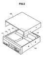
- FIG. 2 attached herewith shows an example of the entire structure of an electronic apparatus having a liquid cooling system therein, according to one embodiment of the present invention.
- a personal computer such as, of the desktop type, for example.
- the main portion of the desktop type personal computer comprises a housing 100, which is formed from a metal plate into a cubic shape thereof, for example, and on a front panel portion 101 thereof are provided various kinds of switches, including an electric power switch therein, and indicator lamps, etc. Also, within an inside thereof is disposed a driver device 102, for driving various kinds of external information recording medium, such as, a floppy disk, a CD, and a DVD, etc., so that it positions an opening thereof on the front panel portion 101. Also, a reference numeral 103 in the figure depicts a memory portion provided within the housing 100 mentioned above, comprising a hard disk device, for example. And also, a reference numeral 104 in the figure depicts a cover to be put on the housing 100 mentioned above.
- an electronic circuit portion 105 having a liquid cooling system according to the present invention
- a reference numeral 106 in the figure depicts an electric power source portion for supplying from a commercial electric power source, a desired electric power to each of the portions, including, the driver device 102, the memory portion 103, and the electronic circuit portion 105 mentioned above.
- Fig. 3 attached herewith is shown the electronic circuit portion 105 of the electronic apparatus, the brief structure of which was explained in the above; i.e., within the desktop type personal computer, in particular, mainly around a heat receiving jacket 50 for mounting thereon a heat-generation element, such as, a CPU, as a main or principle structure thereof.
- a heat-generation element such as, a CPU
- a chip 200 of the CPU being the heat-generation element, is mounted on the lower side surface of the heat-receiving jacket 50 mentioned above, being in contact with, directly, therefore it is not illustrated on the figure, herein.
- this electronic circuit portion 105 comprises the above-mentioned heat-receiving (or cooling) jacket 50 for mounting the CPU thereon, a radiator portion 60 for radiating heat generated from the CPU into an outside of the apparatus, a pump 70 for building up a cooling system, and further flow passages are formed by connecting tubes (conduits) 81, 82..., being made of a metal, or an elastic material, such as a rubber or the like, being covered with a metal film, etc., on the outer surface thereof, so as to prevent the liquid coolant inside from leaking outside, for conducting a liquid coolant (for example, a water, or a mixture of water with a so-called anti-freezing solution, such as, propylene glycol, at a predetermined ratio thereof) to each of those portions building up the heat cycle .
- a liquid coolant for example, a water, or a mixture of water with a so-called anti-freezing solution, such as, propylene glycol, at a predetermined ratio thereof
- plate-like shaped fans 72, 72... (in a plural number, such as, three (3) pieces, in the present example), directing into an outside of the apparatus, so as to blow an air onto a large number of metal thin pipes 61, 61... as the constituent elements thereof, which will be mentioned in more detail later, thereby radiating the heat transmitted from the heat receiving jacket 50 mentioned above, compulsively.
- this heat-receiving (or cooling) jacket 50 is a plate-like member, being made of a metal having high heat conductivity, such as cupper or the like, and being formed with a cooling passage within an inside thereof, to conduct or communicated the liquid coolant into the passage thereof, thereby removing (moving) the heat generated from the CPU into the outside.
- Figs. 1(a) and 1(b) attached herewith show an upper view of the circulation pump 70 mentioned above, and at the same time, a vertical cross-section view thereof.
- a field coil 712 building up a D-C motor, as an electric motor for driving the pump rotationally, being molded around the periphery thereof by an insulating resin 713 in one body, and further a ring-like gutter or groove 714 is formed surrounding around the periphery of the field coil 712, and into an inside thereof are disposed magnet electrodes of the DC motor, which will be mentioned later.
- this square-shaped box(i.e., the case) 710 there is formed a suction port 720 of the liquid coolant extending into a central portion thereof.
- This suction port 720 extends a little bit while being bent downwards, at the central porting thereof.
- an outer-ring shaft bearing 715 in an inside thereof is inserted a rotation shaft of the rotor, which will be mentioned later.
- the rotor 30 is built up with a plural number of blades 731, 731... (in the present example, six (6) pieces thereof) formed upon a disk-like member (in the figure, on the lower surface thereof), as is apparent from Figs. 1(a) and 1 (b) and further Figs. 4 (a) and 4 (b) attached herewith.
- this rotor 730 comprises a ring-like portion 732 extending upwards from an outer edge of that disk-like member, and also on an interior wall surface of this ring-like portion 732 is attached a ring-like shaped permanent magnet 733, being positioned (or magnetized) with the N pole and the S pole, alternately, as shown in the figure, for example.
- a rotation shaft 734 which is made of a metal or a ceramic and formed into a cylindrical shape, penetrating through the disk-like member.
- the rotor 730 is inserted into from the below in the figure, while fitting or inserting the rotation shaft 734 thereof into the outer-ring shaft bearing 715 of the box (i.e., the case) 710 and at the same time positioning the ring-like portion 732 thereof within the groove 714, being ring-like in the outer configuration thereof, of the box (i.e., the case) 710 mentioned above.
- a lower portion box (i.e., a case) 740 is attached covering over the entire thereof, so that the plural number of blades 731, 731... of the rotor 730 are received within an inside thereof.
- a pump chamber 741 is defined for suppressing the liquid coolant therein, and further, this pump chamber 741 is formed to be located in the lower side of the electric motor portion for driving the pump rotationally.
- a reference numeral 742 depicts a discharge port for the liquid coolant, which is formed in a portion of the lower box (i.e., the case) 740 mentioned above.
- the flow passages for guiding the liquid coolant in an inside thereof are formed within an inside of the rotation shaft 734, which supports the rotor 730, rotatably, and further on the lower portion of this rotation shaft 734 (i.e., in an area where the blades 731, 731... are formed) are opened a plural number of penetrating holes 735.
- the rotor 730 when stopping the operation thereof, the rotor 730 ends the rotation thereof, and accompanying with this, the cooling liquid guided within the pump chamber 742 is accumulated within an inside of the pump, including bubbles and so on in a portion thereof.
- the circulation pump 70 mentioned above is installed within a part of the main body of the personal computer of the desktop type shown in Fig. 2 mentioned above, and also it can perform the necessary pump operation, with certainty, even in the case if it is disposed in any position within the liquid cooling system having such the structures shown in Fig. 3 mentioned above.
- Fig. 5 attached herewith shows other embodiment of the circulation pump 70 mentioned above, and in this embodiment, the passage, in which the suction port 720' of the liquid coolant is opened, is formed covering over from a side surface of the box (i.e., the case) 710, up to the central portion on the upper surface thereof, while being attaching on the wall surface and bent.
- the passage in which the suction port 720' of the liquid coolant is opened, is formed covering over from a side surface of the box (i.e., the case) 710, up to the central portion on the upper surface thereof, while being attaching on the wall surface and bent.
- the liquid coolant upon when stopping the operation of the circulation pump 70, the liquid coolant, which has been circulating up to that time, can easily stay in the suction port 720' formed to be bent, and also in that instance, in particular, the liquid coolant flows into the rotation shaft 734 of the rotor 730 mentioned above, and at the same time, the gaseous component mixing into a portion thereof moves into an upper side of the suction port 720'.
- the pump will never run idle, even when it is resumed (started), again, of the operation after the temporal stoppage thereof, since the liquid coolant fills up always within the pump chamber 741 receiving the blades 731 within the inside thereof, thereby enabling the pump operation of the liquid coolant, with certainty.
- Fig. 6 attached herewith shows further other embodiment of the circulation pump 70 mentioned in the above.
- a portion 743 of the lower portion box (i.e., the case) 740, building up the side wall of the pump chamber 741 mentioned above, is extended upwards; thus, the opening of the discharge port 742 to the pump chamber 741 is disposed, so that the position thereof comes to be upper than that of the centrifugal blades 731, 731... of the rotor 730.
- the suction port 720" for the liquid coolant are formed in one body, together with the discharge port 742 mentioned above, on the lower box (i.e., the case) 740 building up the circulation pump 70 mentioned above. Namely, as is apparent from the figure, this suction port 720", differing from the embodiment mentioned above, is attached on the side surface of the circulation pump 70.
- this suction port 720 reaches up to the lower surface of the lower box (i.e., the case) 740, after bending upwards, once, and thereafter, it extends on the lower surface of the lower box (i.e., the case) up to the central portion thereof (i.e., the lower surface extending portion 721), and it opens directing from a lower wall surface 744 in vicinity of the central portion of the rotor 730 mentioned above, into an inside of the pump chamber 741.
- a rod-like rotating shaft 734' is attached at the central portion of the rotor 730, and on the other hand, on the side of the lower box (i.e., the case) 740 is attached a plate-like outer-ring shaft bearing 715' , into the hollow portion thereof the rod-like rotation shaft 734' is inserted, thereby supporting the rotor 730, rotatably.
- the rotor 730 also stops the rotation thereof. And, accompanying with this, the liquid coolant guided into the pump chamber 742 accumulates within the inside of the pump, containing bubbles and so on, in a part thereof. In that instance, as was mentioned above, since the position of the discharge port 742 opening into the pump chamber 741 is arranged so that it comes to be lower than that the centrifugal blades 731, 731...
- Fig. 7 attached herewith shows other liquid cooling system, according to further other embodiment of the present invention.
- the numeral references being same to those shown in Fig. 3 mentioned above depict the constituent elements, which are same to those shown in the embodiment mentioned above.
- a coolant tank 200 is further provided between the radiator 60 and the circulation pump 70 mentioned above, building up the cooling system, for the purpose of storing or accumulating the liquid coolant; e.g., the water or the mixture of the water and the anti-freezing solution, such as, propylene glycol or the like, in an inside thereof, to be circulated within the inside of the system.
- the liquid coolant e.g., the water or the mixture of the water and the anti-freezing solution, such as, propylene glycol or the like
- this coolant tank 200 is located horizontally, as is indicated by solid lines in the figure, or vertically, as is indicated by broken lines in the figure, for example, depending upon the restriction of the space within an inside thereof, for example, when it is disposed within the inside of the housing 100 of the desktop type personal computer shown in Fig. 2 in the above.
- this coolant tank 200 has the structure, as shown in Figs. 8(a) and 8(b) attached herewith, wherein the coolant storage space defined within the inside thereof is divided into a plural number of spaces (for example, three (3) spaces SP1, SP2 and SP3, in the present embodiment), with forming labylinth by combining partition walls 201, 202, 203 and 204, each having about "L"-like cross-section shape.
- a reference numeral 205 in the figure indicates an inlet for the liquid coolant flowing into from the radiator 60 mentioned above, and 206 an outlet for the liquid coolant flowing out into the circulation pump 70 mentioned above.
- reference numerals 206 and 207 indicate portions of the partition walls 202 and 204, each having the "L"-like cross-section; thus, an opening portion that is formed at the position in the vicinity of an outer periphery of the tank.
- the liquid cooling system being applicable into the electronic apparatus, such as, the personal computers, of so-called the desktop-type and the notebook-type, and further the server, etc., easily, and having a high cooling efficiency with using the pump suitable for small-sizing thereof, and also the electronic apparatus having such therein, thereby enabling to dissolve the problems at the time of starting mentioned above, in particular, even when applying the centrifugal pump therein.
Landscapes
- Engineering & Computer Science (AREA)
- Microelectronics & Electronic Packaging (AREA)
- Physics & Mathematics (AREA)
- General Engineering & Computer Science (AREA)
- Theoretical Computer Science (AREA)
- Mechanical Engineering (AREA)
- General Physics & Mathematics (AREA)
- Thermal Sciences (AREA)
- Human Computer Interaction (AREA)
- Condensed Matter Physics & Semiconductors (AREA)
- Computer Hardware Design (AREA)
- Power Engineering (AREA)
- Cooling Or The Like Of Semiconductors Or Solid State Devices (AREA)
- Cooling Or The Like Of Electrical Apparatus (AREA)
- Structures Of Non-Positive Displacement Pumps (AREA)
Abstract
A liquid cooling system being freely
applicable to various kinds of electronic apparatuses, for
cooling a CPU, which is mounted within a
housing (100), the system comprises: a cooling jacket (50), a
radiator (60) and a circulation pump, wherein the circulation pump is
built up with a centrifugal pump, in which a rotor (730) having a plural
number of blades formed in a centrifugal manner, a pump chamber (741)
receiving the rotor in an inside thereof, and a field coil (712) of an
electric motor for driving the rotor rotationally are formed into one
body, and the pump chamber is disposed to be located below the electric
motor, thereby achieving the structure so that a liquid coolant fills up
the pump chamber when stopping, in spite of the disposition of the
circulation pump.
Description
The present invention relates to an electronic apparatus,
such as, a personal computer, being so-called a desktop-type or
a notebook-type, or a server, etc., and in particular, it relates
to a liquid cooling system being able to cool down a heat-generation
element mounted within an inside thereof, such as, a semiconductor
integrated element, effectively with an aid of a liquid refrigerant
or coolant, and further an electronic apparatus having such the
liquid cooling system therein.
In order to maintain a normal operation thereof, cooling
is necessary for the heat-generation element, such as, the
semiconductor IC element, being mounted within an electronic
apparatus, including a personal computer, of called the
desktop-type or the notebook-type, as well as, a server, etc.,
and in particular, the heat-generation element, such as, a CPU
(Central Processing Unit), as a representative one thereof, for
example. For this reason, conventionally, such the cooling is
achieved generally by using a heat transfer element, being
so-called a heat sink that is formed with fins thereon, as well
as a fan, being provided for sending a cooling air thereto. However,
small-sizing and high integration of such the semiconductor IC
element, such as the heat-generation element, in recent years,
brings about localization of the heat generating at a portion
thereof within the heat-generation element, and also for this
reason, attention comes to be paid onto a cooling system of a liquid
type of using the liquid coolant therein, such as a water, for
example, being high in the cooling efficiency thereof, in the place
of the conventional cooling system of an air-cooling type.
Namely, with the liquid cooling system of being high in the
cooling efficiency thereof, which is used in the personal computer,
of so-called the desktop-type or the notebook-type, and also the
server, etc., as is known from the following patent documents,
for example, in general, an element being so-called by a
heat-receiving (or cooler) jacket is mounted on the surface of
the heat-generating element, i.e., the CPU, directly, while
conducting the liquid coolant within a flow passage formed within
the heat-receiving jacket, so as to transmit or convey the heat
generated from the CPU to the coolant flowing within the jacket
mentioned above, thereby cooling down the heat-generating element
with high efficiency. Further, in such the cooling system of the
liquid-cooling type, normally, a heat cycle is made up with the
cooler jacket, as the heat-receiving portion thereof, and in more
details thereof, it comprises a circulation pump for circulating
the liquid coolant mentioned above within the cycle, so-called
a radiator, being a heat-radiation portion for irradiating heat
of the liquid coolant mentioned above into an outside, and further
a coolant tank provided in a part of the cycle depending on the
necessity thereof. And, those are connected through a tube made
of a metal and/or an elastic material, such as rubber or the like.
With the cooling system of the conventional arts mentioned
above, in particular, the cooling system of the liquid type, being
high in the cooling efficiency, to be used in the personal computer,
such as, of the desktop type or the notebook type, and also the
server, etc., normally, as a circulation pump to be provided in
a part of the heat cycle thereof for driving the liquid coolant,
there is applied a pump of the so-called centrifugal type, due
to the reasons that an amount of flow obtained therefrom it is
large, that it is free from the deterioration due to abrasion and
also small in the noises generated therefrom, since it includes
only a small portion sliding therein.
On the other hand, in spite of such the advantages mentioned
above, however with such the pump of the centrifugal type mentioned
above, due to the structure and/or the principle thereof (i.e.,
being small in capacity of self-feeding, differing form the pump
of the volume type, etc.), there is a necessity of filling up the
liquid coolant, as a body to be driven therewith, within the pump
chamber thereof, in particular, when starting up thereof. Namely,
if there is not filled with a sufficient amount of the liquid coolant
as a body to be driven within the pump chamber thereof, when it
starts up, the centrifugal pump makes so-called an idling, and
depending upon the case, it results into a problem that an electric
motor for rotationally driving the pump burns out, or a shaft thereof
fastens, etc. For this reason, in the case where applying such
the pump of the centrifugal type, it is located in a lower portion
of the liquid coolant in the disposition thereof.
However, in an electronic apparatus, including a personal
computer, of so-called the desktop-type or the notebook-type, and
also a server, etc., accompanying the demands upon small-sizing
of the equipment itself in recent years, there is also strongly
made a requirement of making small the cooling system in the sized,
to be used in this. For such the reasons, due to the high cooling
efficiency thereof, attentions are paid upon the cooling system
of the liquid type, in particular, with using the liquid coolant,
such as, water, for example, and also applying the pump of the
centrifugal type therein. However, due to the requirement of
small-sizing thereof, it is not necessarily in such a situation
that the pump can satisfy such the requirement on the disposition
or posture thereof mentioned above, fully.
Then, according to the present invention, being accomplished
by taking the drawbacks of the conventional arts mentioned above
into the consideration thereof, in more details, it is an object
to provide an electronic apparatus for dissolving such the problems
coming up in the cooling system of the liquid type, applying the
pump of the centrifugal type therein; in particular, a cooling
system of the structure being applicable into a personal computer,
of so-called the desktop-type or the notebook-type, and/or a server,
etc., easily, and further, to an electronic apparatus having such
the cooling system therein.
According to the present invention, for accomplishing such
the object mentioned above, firstly, there is provided an
electronic apparatus, installing a semiconductor element within
a housing thereof, which necessitates cooling for maintaining
normal operation thereof, in a part of the housing, and having
a cooling system, within said housing or in a part thereof, said
cooling system, comprising: a cooling jacket, being thematically
connected with said semiconductor element, for transmitting heat
generated therein to a liquid coolant flowing within an inside
thereof; a radiator for radiating the heat transmitted into the
liquid coolant within said cooling jacket into an outside of the
apparatus; and a circulation pump for circulating said liquid
coolant in a loop, including said cooling jacket and said radiator
therein, wherein: said circulation pump is built up with a rotor
formed with a plural number of blades in a centrifugal manner,
a pump chamber receiving said rotor, in a rotatable manner, within
an inside thereof, and an electric motor for rotationally driving
said rotor, being formed together into one body, and said pump
chamber is located in a lower portion of said electric motor.
Also, according to the present invention, in the electronic
apparatus as described in the above, it is preferable that said
circulation pump building up said liquid cooling system has an
inlet opening passage for guiding the liquid coolant into said
pump chamber, and said inlet opening passage is formed, extending
from an upper portion of said pump chamber to a lower portion thereof ,
and further that said inlet opening passage is formed within an
inside of a rotation shaft, for supporting said rotor, rotatabley,
in said circulation pump. Also, according to the present invention,
in the electronic apparatus as described in the above, it is
preferable that an outlet of the liquid coolant, coming out from
said circulation pump building up said liquid cooling system, is
formed at a position upper than the position of the blades of said
rotor, which is disposed within said pump chamber.
In addition thereof, according to the present invention,
in the electronic apparatus as described in the above, it is
preferable that said liquid cooling system further comprises a
tank, which can supply the liquid coolant therein, always
irrespective of direction of disposition thereof, and an outlet
of said tank is connected to an inlet of said circulation pump.
Further, according to the present invention, for
accomplishing the object mentioned above, there is also provided
a liquid cooling system, for cooling a semiconductor element
generating heat therefrom, comprising: a cooling jacket, being
thematically connected with said semiconductor element, for
transmitting heat generated therein to a liquid coolant flowing
within an inside thereof; a radiator for radiating the heat
transmitted into the liquid coolant within said cooling jacket
into an outside of the apparatus; and a circulation pump for
circulating said liquid coolant in a loop, including said cooling
jacket and said radiator therein, wherein: said circulation pump
is built up with a rotor formed with a plural number of blades
in a centrifugal manner, a pump chamber receiving said rotor, in
a rotatable manner, within an inside thereof, and an electric motor
for rotationally driving said rotor, being formed together into
one body, and said pump chamber is located in a lower portion of
said electric motor.
Also, according to the present invention, in the liquid
cooling system as described in the above, it is preferable that
said circulation pump building up said liquid cooling system has
an inlet opening passage for guiding the liquid coolant into said
pump chamber, and said inlet opening passage is formed, extending
froman upper portion of said pump chamber to a lower portion thereof.
Also, according to the present invention, in the liquid
cooling system as described in the above, it is preferable that
said inlet opening passage is formed within an inside of a rotation
shaft, for supporting said rotor, rotatabley, in said circulation
pump, and further that an outlet of the liquid coolant, coming
out from said circulation pump building up said liquid cooling
system, is formed at a position upper than the position of the
blades of said rotor, which is disposed within said pump chamber.
In addition thereto, according to the present invention,
in the liquid cooling system as described in the above, it is
preferable that said liquid cooling system further comprises a
tank, which can supply the liquid coolant therein, always
irrespective of direction of disposition thereof, and an outlet
of said tank is connected to an inlet of said circulation pump.
Those and other features, objects and advantages of the
present invention will become more apparent from the following
description when taken in conjunction with the accompanying
drawings wherein:
Hereinafter, explanation will be given about the embodiments
according to the present invention, in details thereof, by
referring to the drawings attached herewith.
First of all, Fig. 2 attached herewith shows an example of
the entire structure of an electronic apparatus having a liquid
cooling system therein, according to one embodiment of the present
invention. However, in this embodiment is shown a case, where the
present invention is applied into a main part or portion of a personal
computer, such as, of the desktop type, for example.
As shown in the figure, the main portion of the desktop type
personal computer comprises a housing 100, which is formed from
a metal plate into a cubic shape thereof, for example, and on a
front panel portion 101 thereof are provided various kinds of
switches, including an electric power switch therein, and indicator
lamps, etc. Also, within an inside thereof is disposed a driver
device 102, for driving various kinds of external information
recording medium, such as, a floppy disk, a CD, and a DVD, etc.,
so that it positions an opening thereof on the front panel portion
101. Also, a reference numeral 103 in the figure depicts a memory
portion provided within the housing 100 mentioned above, comprising
a hard disk device, for example. And also, a reference numeral
104 in the figure depicts a cover to be put on the housing 100
mentioned above.
While on a rear side of the housing 100 is disposed an
electronic circuit portion 105, having a liquid cooling system
according to the present invention, and a reference numeral 106
in the figure depicts an electric power source portion for supplying
from a commercial electric power source, a desired electric power
to each of the portions, including, the driver device 102, the
memory portion 103, and the electronic circuit portion 105
mentioned above.
Next, in Fig. 3 attached herewith is shown the electronic
circuit portion 105 of the electronic apparatus, the brief
structure of which was explained in the above; i.e., within the
desktop type personal computer, in particular, mainly around a
heat receiving jacket 50 for mounting thereon a heat-generation
element, such as, a CPU, as a main or principle structure thereof.
However, in this embodiment, a chip 200 of the CPU, being the
heat-generation element, is mounted on the lower side surface of
the heat-receiving jacket 50 mentioned above, being in contact
with, directly, therefore it is not illustrated on the figure,
herein.
And, as is apparent from the figure, this electronic circuit
portion 105 comprises the above-mentioned heat-receiving (or
cooling) jacket 50 for mounting the CPU thereon, a radiator portion
60 for radiating heat generated from the CPU into an outside of
the apparatus, a pump 70 for building up a cooling system, and
further flow passages are formed by connecting tubes (conduits)
81, 82..., being made of a metal, or an elastic material, such as
a rubber or the like, being covered with a metal film, etc., on
the outer surface thereof, so as to prevent the liquid coolant
inside from leaking outside, for conducting a liquid coolant (for
example, a water, or a mixture of water with a so-called
anti-freezing solution, such as, propylene glycol, at a
predetermined ratio thereof) to each of those portions building
up the heat cycle . Also, in a part of the radiator portion 60 mentioned
above, there are attached plate-like shaped fans 72, 72... (in a
plural number, such as, three (3) pieces, in the present example),
directing into an outside of the apparatus, so as to blow an air
onto a large number of metal thin pipes 61, 61... as the constituent
elements thereof, which will be mentioned in more detail later,
thereby radiating the heat transmitted from the heat receiving
jacket 50 mentioned above, compulsively. Further, this
heat-receiving (or cooling) jacket 50 is a plate-like member, being
made of a metal having high heat conductivity, such as cupper or
the like, and being formed with a cooling passage within an inside
thereof, to conduct or communicated the liquid coolant into the
passage thereof, thereby removing (moving) the heat generated from
the CPU into the outside.
Following to the above, Figs. 1(a) and 1(b) attached herewith
show an upper view of the circulation pump 70 mentioned above,
and at the same time, a vertical cross-section view thereof. Namely,
in this circulation pump 70, as shown in those figures, within
an inside of a box (i.e., a case) 710 having a shape of quadrate
or square in an outer configuration thereof, a field coil 712
building up a D-C motor, as an electric motor for driving the pump
rotationally, being molded around the periphery thereof by an
insulating resin 713 in one body, and further a ring-like gutter
or groove 714 is formed surrounding around the periphery of the
field coil 712, and into an inside thereof are disposed magnet
electrodes of the DC motor, which will be mentioned later. Also,
on an upper surface of this square-shaped box(i.e., the case) 710,
there is formed a suction port 720 of the liquid coolant extending
into a central portion thereof. This suction port 720 extends a
little bit while being bent downwards, at the central porting
thereof. Further, as is apparent from the figures, at the central
portion of the square-shaped box (i.e., the case) 710, there is
attached so-called an outer-ring shaft bearing 715, in an inside
thereof is inserted a rotation shaft of the rotor, which will be
mentioned later.
On the other hand, the rotor 30 is built up with a plural
number of blades 731, 731... (in the present example, six (6) pieces
thereof) formed upon a disk-like member (in the figure, on the
lower surface thereof), as is apparent from Figs. 1(a) and 1 (b)
and further Figs. 4 (a) and 4 (b) attached herewith. Then, this rotor
730 comprises a ring-like portion 732 extending upwards from an
outer edge of that disk-like member, and also on an interior wall
surface of this ring-like portion 732 is attached a ring-like shaped
permanent magnet 733, being positioned (or magnetized) with the
N pole and the S pole, alternately, as shown in the figure, for
example. In addition thereto, at the central portion of this rotor
730 made from the disk-like member, there is attached so-called
a rotation shaft 734, which is made of a metal or a ceramic and
formed into a cylindrical shape, penetrating through the disk-like
member.
Namely, as is apparent from the figures mentioned above,
the rotor 730 is inserted into from the below in the figure, while
fitting or inserting the rotation shaft 734 thereof into the
outer-ring shaft bearing 715 of the box (i.e., the case) 710 and
at the same time positioning the ring-like portion 732 thereof
within the groove 714, being ring-like in the outer configuration
thereof, of the box (i.e., the case) 710 mentioned above. Thereafter,
on the lower surface of the box (i.e., the case) 710, a lower portion
box (i.e., a case) 740 is attached covering over the entire thereof,
so that the plural number of blades 731, 731... of the rotor 730
are received within an inside thereof. Thus, between the upper
surface of this lower box (i.e., the case) 740 and the lower surface
of the rotor mentioned above, a pump chamber 741 is defined for
suppressing the liquid coolant therein, and further, this pump
chamber 741 is formed to be located in the lower side of the electric
motor portion for driving the pump rotationally. Also, a reference
numeral 742 depicts a discharge port for the liquid coolant, which
is formed in a portion of the lower box (i.e., the case) 740 mentioned
above.
In this manner, in the circulation pump 70, the structure
of which was mentioned in the above, the flow passages for guiding
the liquid coolant in an inside thereof are formed within an inside
of the rotation shaft 734, which supports the rotor 730, rotatably,
and further on the lower portion of this rotation shaft 734 (i.e.,
in an area where the blades 731, 731... are formed) are opened a
plural number of penetrating holes 735. For this reason, when
operating, the liquid coolant reaching into the inside of the
rotation shaft 734 of the rotor 730 is guided into an inside of
the pump chamber 741 mentioned above, and is compressed therein
with the centrifugal force, by means of the plural number of the
blades 731, 731..., and thereafter being discharged from the
discharge port 742 mentioned above.
On the other hand, within the calculation pump 70, when
stopping the operation thereof, the rotor 730 ends the rotation
thereof, and accompanying with this, the cooling liquid guided
within the pump chamber 742 is accumulated within an inside of
the pump, including bubbles and so on in a portion thereof. In
that instance, as is apparent from Figs. 4(a) and 4(b) mentioned
above, in the vicinity of the disk-like member, the penetrating
holes 736, 736... for use of babble removal are formed, respectively,
on the lower surface of which the centrifugal blades 731, 731...,
therefore, while a portion thereof moves into an upper portion
thereof through the rotation shaft 734 mentioned above, the gas
moves into an outside of the pump chamber 741, in more details,
into an upper portion of the ring-like groove 714 formed in the
box (i.e., the case) 710, through the penetrating holes 736, 736...
for use of bubble removal, even if the gas mixing therein is separated
from the liquid coolant. In other words, within the circulation
pump 70 having such the structure mentioned above, only the liquid
coolant accumulates within the pump chamber 741, however the gas
mixing in the liquid coolant never remains within the pump chamber
741, even when stopping.
For this reason, within the circulation pump 70 having such
the structure mentioned above, even when the operation is resumed
(or stared) again, after temporal stoppage thereof, since only
the liquid coolant always fills up within the pump chamber 741,
fully, which receives the blades 731 within the inside thereof,
then the pump will never run idle, therefore it is possible to
obtain (re-start) the pump operation of the liquid coolant, with
certainty. Namely, the circulation pump 70 mentioned above is
installed within a part of the main body of the personal computer
of the desktop type shown in Fig. 2 mentioned above, and also it
can perform the necessary pump operation, with certainty, even
in the case if it is disposed in any position within the liquid
cooling system having such the structures shown in Fig. 3 mentioned
above.
Also, Fig. 5 attached herewith shows other embodiment of
the circulation pump 70 mentioned above, and in this embodiment,
the passage, in which the suction port 720' of the liquid coolant
is opened, is formed covering over from a side surface of the box
(i.e., the case) 710, up to the central portion on the upper surface
thereof, while being attaching on the wall surface and bent. Namely,
with such the structure, upon when stopping the operation of the
circulation pump 70, the liquid coolant, which has been circulating
up to that time, can easily stay in the suction port 720' formed
to be bent, and also in that instance, in particular, the liquid
coolant flows into the rotation shaft 734 of the rotor 730 mentioned
above, and at the same time, the gaseous component mixing into
a portion thereof moves into an upper side of the suction port
720'. Namely, in the similar manner to that of the embodiment
mentioned above, the pump will never run idle, even when it is
resumed (started), again, of the operation after the temporal
stoppage thereof, since the liquid coolant fills up always within
the pump chamber 741 receiving the blades 731 within the inside
thereof, thereby enabling the pump operation of the liquid coolant,
with certainty.
Next, Fig. 6 attached herewith shows further other embodiment
of the circulation pump 70 mentioned in the above. In this example,
differing from the embodiment mentioned above, first a portion
743 of the lower portion box (i.e., the case) 740, building up
the side wall of the pump chamber 741 mentioned above, is extended
upwards; thus, the opening of the discharge port 742 to the pump
chamber 741 is disposed, so that the position thereof comes to
be upper than that of the centrifugal blades 731, 731... of the rotor
730.
Also, in the present embodiment, the suction port 720" for
the liquid coolant are formed in one body, together with the
discharge port 742 mentioned above, on the lower box (i.e., the
case) 740 building up the circulation pump 70 mentioned above.
Namely, as is apparent from the figure, this suction port 720",
differing from the embodiment mentioned above, is attached on the
side surface of the circulation pump 70. And, in more details,
this suction port 720", as is apparent from the figure, reaches
up to the lower surface of the lower box (i.e., the case) 740,
after bending upwards, once, and thereafter, it extends on the
lower surface of the lower box (i.e., the case) up to the central
portion thereof (i.e., the lower surface extending portion 721),
and it opens directing from a lower wall surface 744 in vicinity
of the central portion of the rotor 730 mentioned above, into an
inside of the pump chamber 741. However, in this example, in the
place of the hollow rotation shaft 734 mentioned above, a rod-like
rotating shaft 734' is attached at the central portion of the rotor
730, and on the other hand, on the side of the lower box (i.e.,
the case) 740 is attached a plate-like outer-ring shaft bearing
715' , into the hollow portion thereof the rod-like rotation shaft
734' is inserted, thereby supporting the rotor 730, rotatably.
With such the structure of the further other embodiment
mentioned above, as is apparent from the figure, when the pump
70 stops, the rotor 730 also stops the rotation thereof. And,
accompanying with this, the liquid coolant guided into the pump
chamber 742 accumulates within the inside of the pump, containing
bubbles and so on, in a part thereof. In that instance, as was
mentioned above, since the position of the discharge port 742
opening into the pump chamber 741 is arranged so that it comes
to be lower than that the centrifugal blades 731, 731... of the rotor,
and further since the suction port 720" is opened at around the
central portion of the pump chamber 741 from a lower wall surface
thereof, after being bent up and down, once, on the side surface
of the pump, the gas is guided into the outside passing through
the opening of the discharge port 742 disposed at the position
above than the centrifugal blades 731, 731... of the rotor 730, even
if the gas mixing therein is separated from the liquid coolant
accumulated within the pump, therefore only the liquid coolant
is accumulated within an inside of the pump chamber 741, which
receives the centrifugal blades 731, 731... therein. In other words,
during the time when stopping, no gas mixing into the liquid coolant
is accumulated within the pump chamber 741, thereby bringing about
no idling run of the pump when it is re-started.
Following to the above, Fig. 7 attached herewith shows other
liquid cooling system, according to further other embodiment of
the present invention. However, in this embodiment, the numeral
references being same to those shown in Fig. 3 mentioned above
depict the constituent elements, which are same to those shown
in the embodiment mentioned above. Namely, as is apparent from
those figures, in this further other embodiment, between the
radiator 60 and the circulation pump 70 building up the cooling
system, a coolant tank 200 is further provided between the radiator
60 and the circulation pump 70 mentioned above, building up the
cooling system, for the purpose of storing or accumulating the
liquid coolant; e.g., the water or the mixture of the water and
the anti-freezing solution, such as, propylene glycol or the like,
in an inside thereof, to be circulated within the inside of the
system. However, there may be cases where, this coolant tank 200
is located horizontally, as is indicated by solid lines in the
figure, or vertically, as is indicated by broken lines in the figure,
for example, depending upon the restriction of the space within
an inside thereof, for example, when it is disposed within the
inside of the housing 100 of the desktop type personal computer
shown in Fig. 2 in the above.
Then, this coolant tank 200 has the structure, as shown in
Figs. 8(a) and 8(b) attached herewith, wherein the coolant storage
space defined within the inside thereof is divided into a plural
number of spaces (for example, three (3) spaces SP1, SP2 and SP3,
in the present embodiment), with forming labylinth by combining
partition walls 201, 202, 203 and 204, each having about "L"-like
cross-section shape. Also, a reference numeral 205 in the figure
indicates an inlet for the liquid coolant flowing into from the
radiator 60 mentioned above, and 206 an outlet for the liquid coolant
flowing out into the circulation pump 70 mentioned above. Further,
reference numerals 206 and 207 indicate portions of the partition
walls 202 and 204, each having the "L"-like cross-section; thus,
an opening portion that is formed at the position in the vicinity
of an outer periphery of the tank.
In accordance with the coolant tank 200 having such the
structure therein, as is apparent from Figs. 8(a) and 8(b) mentioned
above, and further Figs. 9(a) and 9(b) attached herewith, if a
bubble flows into the inlet 205 of the tank, mixing into a portion
of the liquid coolant while the portion thereof leaks out through
vaporization, etc., into an outside thereof, during it circulates
within the cooling system, however, only the liquid coolant, but
excluding the bubble therefrom, is always sent out from the outlet
205 to the circulation pump mentioned above. Therefore, it is
possible to protect the circulation pump, building up an important
constituent element in the cooling system of using the liquid
coolant therein, in particular, from the idling due to the gas
existing within the pump chamber 741 when it is started, and also
from the damage of the circulation pump in itself, depending on
a case, with certainty; thereby, obtaining the electronic apparatus
having the cooling system superior in the cooling capacity, which
can be applied into the personal computer, of so-called the desktop
type or the notebook-type, and also the server, etc.
Though the mentioning given in the above was made only about
the one example of the case where the liquid cooling system of
using the liquid coolant therein according to the present invention
is applied, in particular, into the main part of the personal
computer of so-called the desk-top type, however the present
invention can be also applied into the personal computer of
so-called the notebook type and the server, etc. However, in that
case, an in particular, in the former case, it would be obvious
matter that, for the person stilled in the art, for example, in
particular, as the radiator portion 60 among the constituent
elements thereof, a radiation plate, which is built up with a metal
plate attached with a conduit made of a metal, is attached on the
cover side thereof, in more details thereof, the reverse side
surface of the liquid crystal display device in the place of that
mentioned in the above.
Namely, according to the present invention fully mentioned
above, it is possible to provide the liquid cooling system, being
applicable into the electronic apparatus, such as, the personal
computers, of so-called the desktop-type and the notebook-type,
and further the server, etc., easily, and having a high cooling
efficiency with using the pump suitable for small-sizing thereof,
and also the electronic apparatus having such therein, thereby
enabling to dissolve the problems at the time of starting mentioned
above, in particular, even when applying the centrifugal pump
therein.
The present invention may be embodied in other specific forms
without departing from the spirit or essential feature or
characteristics thereof. The present embodiment(s) is/are
therefore to be considered in all respects as illustrative and
not restrictive, the scope of the invention being indicated by
the appended claims rather than by the forgoing description and
range of equivalency of the claims are therefore to be embraces
therein.
Claims (10)
- An electronic apparatus, installing a semiconductor element within a housing thereof, which necessitates cooling for maintaining normal operation thereof, in a part of the housing, and having a cooling system, within said housing (100) or in a part thereof, said cooling system, comprising:a cooling jacket (50), being thematically connected with said semiconductor element, for transmitting heat generated therein to a liquid coolant flowing within an inside thereof;a radiator (60) for radiating the heat transmitted into the liquid coolant within said cooling jacket (50) into an outside of the apparatus; anda circulation pump (70) for circulating said liquid coolant in a loop, including said cooling jacket (50) and said radiator (60) therein, wherein:said circulation pump (70) is built up with a rotor (730) formed with a plural number of blades (731, 732) in a centrifugal manner, a pump chamber (741) receiving said rotor (730), in a rotatable manner, within an inside thereof, and an electric motor for rotationally driving said rotor (730), being formed together into one body, and said pump chamber (741) is located in a lower portion of said electric motor.
- Electronic apparatus according to claim 1, characterized in that said circulation pump (70) building up said liquid cooling system has an inlet opening passage for guiding the liquid coolant into said pump chamber (741), and said inlet opening passage is formed, extending from an upper portion of said pump chamber (741) to a lower portion thereof.
- Electronic apparatus according to claim 2 , characterized in that said inlet opening passage is formed within an inside of a rotation shaft (734), for supporting said rotor (730), rotatably, in said circulation pump (70).
- Electronic apparatus according to any of claims 1 to 3, characterized in that an outlet of the liquid coolant, coming out from said circulation pump (70) building up said liquid cooling system, is formed at a position upper than the position of the blades (731, 732) of said rotor (730), which is disposed within said pump chamber (741).
- Electronic apparatus according to any of claims 1 to 4, characterized in that said liquid cooling system further comprises a tank, which can supply the liquid coolant therein, always irrespective of direction of disposition thereof, and an outlet of said tank is connected to an inlet of said circulation pump (70).
- A liquid cooling system, for cooling a semiconductor element generating heat therefrom, comprising:a cooling jacket (50), being thematically connected with said semiconductor element, for transmitting heat generated therein to a liquid coolant flowing within an inside thereof;a radiator (60) for radiating the heat transmitted into the liquid coolant within said cooling jacket (50) into an outside of the apparatus; anda circulation pump (70) for circulating said liquid coolant in a loop, including said cooling jacket (50) and said radiator (60) therein, wherein:said circulation pump (70) is built up with a rotor (730) formed with a plural number of blades (731, 732) in a centrifugal manner, a pump chamber (741) receiving said rotor (730), in a rotatable manner, within an inside thereof ,and an electric motor for rotationally driving said rotor (730), being formed together into one body, and said pump chamber (741) is located in a lower portion of said electric motor.
- Liquid cooling system according to claim 6, characterized in that said circulation pump (70) building up said liquid cooling system has an inlet opening passage for guiding the liquid coolant into said pump chamber (741), and said inlet opening passage is formed, extending from an upper portion of said pump chamber (741) to a lower portion thereof.
- Liquid cooling system according to claim 6 or 7, characterized in that said inlet opening passage is formed within an inside of a rotation shaft (734), for supporting said rotor (730), rotatably, in said circulation pump (70).
- Liquid cooling system according to any of claims 6 to 8, characterized in that an outlet of the liquid coolant, coming out from said circulation pump (70) building up said liquid cooling system, is formed at a position upper than the position of the blades (731, 732) of said rotor (730), which is disposed within said pump chamber (741).
- Liquid cooling system according to any of claims 6 to 9, characterized in that said liquid cooling system further comprises a tank, which can supply the liquid coolant therein, always irrespective of direction of disposition thereof, and an outlet of said tank is connected to an inlet of said circulation pump (70).
Applications Claiming Priority (2)
| Application Number | Priority Date | Filing Date | Title |
|---|---|---|---|
| JP2004037920 | 2004-02-16 | ||
| JP2004037920A JP2005229020A (en) | 2004-02-16 | 2004-02-16 | Liquid-cooled system and electronic equipment having the same |
Publications (1)
| Publication Number | Publication Date |
|---|---|
| EP1571533A2 true EP1571533A2 (en) | 2005-09-07 |
Family
ID=34747403
Family Applications (1)
| Application Number | Title | Priority Date | Filing Date |
|---|---|---|---|
| EP04005451A Withdrawn EP1571533A2 (en) | 2004-02-16 | 2004-03-08 | Liquid cooling system, and electronic apparatus having the same therein |
Country Status (6)
| Country | Link |
|---|---|
| US (1) | US20050178526A1 (en) |
| EP (1) | EP1571533A2 (en) |
| JP (1) | JP2005229020A (en) |
| KR (1) | KR20050081817A (en) |
| CN (1) | CN1658119A (en) |
| TW (1) | TW200529729A (en) |
Families Citing this family (19)
| Publication number | Priority date | Publication date | Assignee | Title |
|---|---|---|---|---|
| US7124811B2 (en) * | 2004-12-31 | 2006-10-24 | Intel Corporation | Systems for integrated pump and cold plate |
| JP2006229142A (en) * | 2005-02-21 | 2006-08-31 | Toshiba Corp | Cooling device and electronic apparatus comprising the same |
| US7228888B2 (en) * | 2005-10-13 | 2007-06-12 | International Business Machines Corporation | Rotatable liquid reservoir for computer cooling |
| US7753662B2 (en) * | 2006-09-21 | 2010-07-13 | Fu Zhun Precision Industry (Shen Zhen) Co., Ltd. | Miniature liquid cooling device having an integral pump therein |
| US9227001B2 (en) | 2010-10-07 | 2016-01-05 | Everheart Systems Inc. | High efficiency blood pump |
| US8432691B2 (en) * | 2010-10-28 | 2013-04-30 | Asetek A/S | Liquid cooling system for an electronic system |
| US20120316711A1 (en) * | 2011-06-08 | 2012-12-13 | Coda Automotive, Inc. | Cooling system with anomaly detection |
| US9689627B2 (en) * | 2013-02-05 | 2017-06-27 | Asia Vital Components Co., Ltd. | Water-cooling device with waterproof stator and rotor pumping unit |
| US10294944B2 (en) * | 2013-03-08 | 2019-05-21 | Everheart Systems Inc. | Flow thru mechanical blood pump bearings |
| CN104421166A (en) * | 2013-08-30 | 2015-03-18 | 刘讯岐 | Super-high-efficiency liquid cooling motor pump |
| CN105338782B (en) * | 2014-05-27 | 2019-03-26 | 展讯通信(上海)有限公司 | A kind of radiator |
| KR102392820B1 (en) * | 2015-05-21 | 2022-05-02 | 주식회사 브라이트론 | The Cooling Fan cooled by Cooling Effect of its Surface of the Spindle Fan Blade |
| CN106053888B (en) * | 2016-05-14 | 2018-11-06 | 刘洋 | A kind of intelligence instrument with heat sinking function |
| US10543036B2 (en) * | 2017-06-13 | 2020-01-28 | Covidien Lp | Systems and methods of cooling surgical instruments |
| CN109890171A (en) * | 2017-12-06 | 2019-06-14 | 泽鸿(广州)电子科技有限公司 | Liquid cooling radiation module |
| JP7181443B2 (en) * | 2018-02-14 | 2022-12-01 | 日本電産サンキョー株式会社 | Cooling system |
| US10746084B2 (en) * | 2018-12-13 | 2020-08-18 | General Electric Company | Liquid driven thermal module and thermal management system |
| CN109696008B (en) * | 2019-01-31 | 2023-09-26 | 深圳市研派科技有限公司 | Fluid cooling device |
| CN112302953B (en) | 2019-07-25 | 2022-10-18 | 台达电子工业股份有限公司 | Pump mechanism, pump system, and method of manufacturing pump mechanism |
Family Cites Families (9)
| Publication number | Priority date | Publication date | Assignee | Title |
|---|---|---|---|---|
| US6021844A (en) * | 1998-06-03 | 2000-02-08 | Batchelder; John Samuel | Heat exchange apparatus |
| US6208512B1 (en) * | 1999-05-14 | 2001-03-27 | International Business Machines Corporation | Contactless hermetic pump |
| US6408937B1 (en) * | 2000-11-15 | 2002-06-25 | Sanjay K. Roy | Active cold plate/heat sink |
| TW561226B (en) * | 2001-09-25 | 2003-11-11 | Matsushita Electric Ind Co Ltd | Ultra-thin pump and cooling system including the pump |
| US6668911B2 (en) * | 2002-05-08 | 2003-12-30 | Itt Manufacturing Enterprises, Inc. | Pump system for use in a heat exchange application |
| US20040052048A1 (en) * | 2002-09-13 | 2004-03-18 | Wu Bo Jiu | Integrated fluid cooling system for electronic components |
| JP3757200B2 (en) * | 2002-09-25 | 2006-03-22 | 株式会社日立製作所 | Electronic equipment with cooling mechanism |
| JP3981628B2 (en) * | 2002-11-28 | 2007-09-26 | 株式会社東芝 | Cooling pump, electrical equipment and personal computer |
| US6827131B1 (en) * | 2003-07-21 | 2004-12-07 | Neng Chao Chang | Apparatus of water-cooled heat sink |
-
2004
- 2004-02-16 JP JP2004037920A patent/JP2005229020A/en active Pending
- 2004-03-01 TW TW093105308A patent/TW200529729A/en unknown
- 2004-03-05 CN CN2004100077620A patent/CN1658119A/en active Pending
- 2004-03-05 US US10/792,719 patent/US20050178526A1/en not_active Abandoned
- 2004-03-06 KR KR1020040015245A patent/KR20050081817A/en not_active Application Discontinuation
- 2004-03-08 EP EP04005451A patent/EP1571533A2/en not_active Withdrawn
Also Published As
| Publication number | Publication date |
|---|---|
| US20050178526A1 (en) | 2005-08-18 |
| TW200529729A (en) | 2005-09-01 |
| JP2005229020A (en) | 2005-08-25 |
| CN1658119A (en) | 2005-08-24 |
| KR20050081817A (en) | 2005-08-19 |
Similar Documents
| Publication | Publication Date | Title |
|---|---|---|
| EP1571533A2 (en) | Liquid cooling system, and electronic apparatus having the same therein | |
| US7301771B2 (en) | Heat-receiving apparatus and electronic equipment | |
| US20060162901A1 (en) | Blower, cooling device including the blower, and electronic apparatus including the cooling device | |
| JP4244703B2 (en) | Cooling system | |
| US7273089B2 (en) | Electronic apparatus having a heat-radiating unit for radiating heat of heat-generating components | |
| US6763880B1 (en) | Liquid cooled radiation module for servers | |
| KR100610734B1 (en) | Liquid cooled system | |
| CN104144594B (en) | pump for water cooler | |
| US20060018775A1 (en) | Liquid circulation system and liquid cooling system therewith | |
| JP2005093604A (en) | Cooling device and electronic apparatus | |
| JP2006234255A (en) | Radiator and liquid cooling system comprising the same | |
| JP2005229030A (en) | Electronic equipment having liquid-cooled system | |
| US20050178528A1 (en) | Electronic apparatus having cooling system, radiator thereof, and method for manufacturing thereof | |
| JP3452059B1 (en) | Cooling device and electronic equipment equipped with it | |
| US20050183848A1 (en) | Coolant tray of liquid based cooling device | |
| US20050264996A1 (en) | Pump, cooling unit and electronic apparatus including cooling unit | |
| JP2006049382A (en) | Cooling device and electronic equipment | |
| JP2004218941A (en) | Cooling device | |
| JP4258292B2 (en) | Cooling system | |
| US20090301692A1 (en) | Electronic Apparatus Cooling Device | |
| US20080011455A1 (en) | Composite heat-dissipating module | |
| JP2007103633A (en) | Cooling device and electronic apparatus including the same | |
| JP2001044679A (en) | Cooling unit | |
| TWM244511U (en) | The water cooler device for interface card of computer | |
| JP2006235915A (en) | Liquid cooling system, and radiating device for the system |
Legal Events
| Date | Code | Title | Description |
|---|---|---|---|
| PUAI | Public reference made under article 153(3) epc to a published international application that has entered the european phase |
Free format text: ORIGINAL CODE: 0009012 |
|
| AK | Designated contracting states |
Kind code of ref document: A2 Designated state(s): AT BE BG CH CY CZ DE DK EE ES FI FR GB GR HU IE IT LI LU MC NL PL PT RO SE SI SK TR |
|
| AX | Request for extension of the european patent |
Extension state: AL LT LV MK |
|
| STAA | Information on the status of an ep patent application or granted ep patent |
Free format text: STATUS: THE APPLICATION HAS BEEN WITHDRAWN |
|
| 18W | Application withdrawn |
Effective date: 20051209 |