EP1570810A1 - Partial pelvic endoprothesis - Google Patents
Partial pelvic endoprothesis Download PDFInfo
- Publication number
- EP1570810A1 EP1570810A1 EP04004256A EP04004256A EP1570810A1 EP 1570810 A1 EP1570810 A1 EP 1570810A1 EP 04004256 A EP04004256 A EP 04004256A EP 04004256 A EP04004256 A EP 04004256A EP 1570810 A1 EP1570810 A1 EP 1570810A1
- Authority
- EP
- European Patent Office
- Prior art keywords
- endoprosthesis according
- pelvic
- pelvic endoprosthesis
- hip
- projection
- Prior art date
- Legal status (The legal status is an assumption and is not a legal conclusion. Google has not performed a legal analysis and makes no representation as to the accuracy of the status listed.)
- Granted
Links
Images


Classifications
-
- A—HUMAN NECESSITIES
- A61—MEDICAL OR VETERINARY SCIENCE; HYGIENE
- A61F—FILTERS IMPLANTABLE INTO BLOOD VESSELS; PROSTHESES; DEVICES PROVIDING PATENCY TO, OR PREVENTING COLLAPSING OF, TUBULAR STRUCTURES OF THE BODY, e.g. STENTS; ORTHOPAEDIC, NURSING OR CONTRACEPTIVE DEVICES; FOMENTATION; TREATMENT OR PROTECTION OF EYES OR EARS; BANDAGES, DRESSINGS OR ABSORBENT PADS; FIRST-AID KITS
- A61F2/00—Filters implantable into blood vessels; Prostheses, i.e. artificial substitutes or replacements for parts of the body; Appliances for connecting them with the body; Devices providing patency to, or preventing collapsing of, tubular structures of the body, e.g. stents
- A61F2/02—Prostheses implantable into the body
- A61F2/30—Joints
- A61F2/32—Joints for the hip
- A61F2/34—Acetabular cups
-
- A—HUMAN NECESSITIES
- A61—MEDICAL OR VETERINARY SCIENCE; HYGIENE
- A61B—DIAGNOSIS; SURGERY; IDENTIFICATION
- A61B17/00—Surgical instruments, devices or methods, e.g. tourniquets
- A61B17/56—Surgical instruments or methods for treatment of bones or joints; Devices specially adapted therefor
- A61B17/58—Surgical instruments or methods for treatment of bones or joints; Devices specially adapted therefor for osteosynthesis, e.g. bone plates, screws, setting implements or the like
- A61B17/68—Internal fixation devices, including fasteners and spinal fixators, even if a part thereof projects from the skin
- A61B17/80—Cortical plates, i.e. bone plates; Instruments for holding or positioning cortical plates, or for compressing bones attached to cortical plates
- A61B17/8061—Cortical plates, i.e. bone plates; Instruments for holding or positioning cortical plates, or for compressing bones attached to cortical plates specially adapted for particular bones
- A61B17/8066—Cortical plates, i.e. bone plates; Instruments for holding or positioning cortical plates, or for compressing bones attached to cortical plates specially adapted for particular bones for pelvic reconstruction
-
- A—HUMAN NECESSITIES
- A61—MEDICAL OR VETERINARY SCIENCE; HYGIENE
- A61F—FILTERS IMPLANTABLE INTO BLOOD VESSELS; PROSTHESES; DEVICES PROVIDING PATENCY TO, OR PREVENTING COLLAPSING OF, TUBULAR STRUCTURES OF THE BODY, e.g. STENTS; ORTHOPAEDIC, NURSING OR CONTRACEPTIVE DEVICES; FOMENTATION; TREATMENT OR PROTECTION OF EYES OR EARS; BANDAGES, DRESSINGS OR ABSORBENT PADS; FIRST-AID KITS
- A61F2/00—Filters implantable into blood vessels; Prostheses, i.e. artificial substitutes or replacements for parts of the body; Appliances for connecting them with the body; Devices providing patency to, or preventing collapsing of, tubular structures of the body, e.g. stents
- A61F2/02—Prostheses implantable into the body
- A61F2/30—Joints
- A61F2/30721—Accessories
- A61F2/30749—Fixation appliances for connecting prostheses to the body
-
- A—HUMAN NECESSITIES
- A61—MEDICAL OR VETERINARY SCIENCE; HYGIENE
- A61F—FILTERS IMPLANTABLE INTO BLOOD VESSELS; PROSTHESES; DEVICES PROVIDING PATENCY TO, OR PREVENTING COLLAPSING OF, TUBULAR STRUCTURES OF THE BODY, e.g. STENTS; ORTHOPAEDIC, NURSING OR CONTRACEPTIVE DEVICES; FOMENTATION; TREATMENT OR PROTECTION OF EYES OR EARS; BANDAGES, DRESSINGS OR ABSORBENT PADS; FIRST-AID KITS
- A61F2/00—Filters implantable into blood vessels; Prostheses, i.e. artificial substitutes or replacements for parts of the body; Appliances for connecting them with the body; Devices providing patency to, or preventing collapsing of, tubular structures of the body, e.g. stents
- A61F2/02—Prostheses implantable into the body
- A61F2/30—Joints
- A61F2/32—Joints for the hip
-
- A—HUMAN NECESSITIES
- A61—MEDICAL OR VETERINARY SCIENCE; HYGIENE
- A61F—FILTERS IMPLANTABLE INTO BLOOD VESSELS; PROSTHESES; DEVICES PROVIDING PATENCY TO, OR PREVENTING COLLAPSING OF, TUBULAR STRUCTURES OF THE BODY, e.g. STENTS; ORTHOPAEDIC, NURSING OR CONTRACEPTIVE DEVICES; FOMENTATION; TREATMENT OR PROTECTION OF EYES OR EARS; BANDAGES, DRESSINGS OR ABSORBENT PADS; FIRST-AID KITS
- A61F2/00—Filters implantable into blood vessels; Prostheses, i.e. artificial substitutes or replacements for parts of the body; Appliances for connecting them with the body; Devices providing patency to, or preventing collapsing of, tubular structures of the body, e.g. stents
- A61F2/02—Prostheses implantable into the body
- A61F2/30—Joints
- A61F2/46—Special tools or methods for implanting or extracting artificial joints, accessories, bone grafts or substitutes, or particular adaptations therefor
- A61F2/4684—Trial or dummy prostheses
-
- A—HUMAN NECESSITIES
- A61—MEDICAL OR VETERINARY SCIENCE; HYGIENE
- A61F—FILTERS IMPLANTABLE INTO BLOOD VESSELS; PROSTHESES; DEVICES PROVIDING PATENCY TO, OR PREVENTING COLLAPSING OF, TUBULAR STRUCTURES OF THE BODY, e.g. STENTS; ORTHOPAEDIC, NURSING OR CONTRACEPTIVE DEVICES; FOMENTATION; TREATMENT OR PROTECTION OF EYES OR EARS; BANDAGES, DRESSINGS OR ABSORBENT PADS; FIRST-AID KITS
- A61F2/00—Filters implantable into blood vessels; Prostheses, i.e. artificial substitutes or replacements for parts of the body; Appliances for connecting them with the body; Devices providing patency to, or preventing collapsing of, tubular structures of the body, e.g. stents
- A61F2/02—Prostheses implantable into the body
- A61F2/30—Joints
- A61F2002/30001—Additional features of subject-matter classified in A61F2/28, A61F2/30 and subgroups thereof
- A61F2002/30108—Shapes
- A61F2002/3011—Cross-sections or two-dimensional shapes
- A61F2002/30138—Convex polygonal shapes
- A61F2002/30143—Convex polygonal shapes hexagonal
-
- A—HUMAN NECESSITIES
- A61—MEDICAL OR VETERINARY SCIENCE; HYGIENE
- A61F—FILTERS IMPLANTABLE INTO BLOOD VESSELS; PROSTHESES; DEVICES PROVIDING PATENCY TO, OR PREVENTING COLLAPSING OF, TUBULAR STRUCTURES OF THE BODY, e.g. STENTS; ORTHOPAEDIC, NURSING OR CONTRACEPTIVE DEVICES; FOMENTATION; TREATMENT OR PROTECTION OF EYES OR EARS; BANDAGES, DRESSINGS OR ABSORBENT PADS; FIRST-AID KITS
- A61F2/00—Filters implantable into blood vessels; Prostheses, i.e. artificial substitutes or replacements for parts of the body; Appliances for connecting them with the body; Devices providing patency to, or preventing collapsing of, tubular structures of the body, e.g. stents
- A61F2/02—Prostheses implantable into the body
- A61F2/30—Joints
- A61F2002/30001—Additional features of subject-matter classified in A61F2/28, A61F2/30 and subgroups thereof
- A61F2002/30108—Shapes
- A61F2002/3011—Cross-sections or two-dimensional shapes
- A61F2002/30138—Convex polygonal shapes
- A61F2002/30154—Convex polygonal shapes square
-
- A—HUMAN NECESSITIES
- A61—MEDICAL OR VETERINARY SCIENCE; HYGIENE
- A61F—FILTERS IMPLANTABLE INTO BLOOD VESSELS; PROSTHESES; DEVICES PROVIDING PATENCY TO, OR PREVENTING COLLAPSING OF, TUBULAR STRUCTURES OF THE BODY, e.g. STENTS; ORTHOPAEDIC, NURSING OR CONTRACEPTIVE DEVICES; FOMENTATION; TREATMENT OR PROTECTION OF EYES OR EARS; BANDAGES, DRESSINGS OR ABSORBENT PADS; FIRST-AID KITS
- A61F2/00—Filters implantable into blood vessels; Prostheses, i.e. artificial substitutes or replacements for parts of the body; Appliances for connecting them with the body; Devices providing patency to, or preventing collapsing of, tubular structures of the body, e.g. stents
- A61F2/02—Prostheses implantable into the body
- A61F2/30—Joints
- A61F2002/30001—Additional features of subject-matter classified in A61F2/28, A61F2/30 and subgroups thereof
- A61F2002/30108—Shapes
- A61F2002/30199—Three-dimensional shapes
- A61F2002/30224—Three-dimensional shapes cylindrical
- A61F2002/30235—Three-dimensional shapes cylindrical tubular, e.g. sleeves
-
- A—HUMAN NECESSITIES
- A61—MEDICAL OR VETERINARY SCIENCE; HYGIENE
- A61F—FILTERS IMPLANTABLE INTO BLOOD VESSELS; PROSTHESES; DEVICES PROVIDING PATENCY TO, OR PREVENTING COLLAPSING OF, TUBULAR STRUCTURES OF THE BODY, e.g. STENTS; ORTHOPAEDIC, NURSING OR CONTRACEPTIVE DEVICES; FOMENTATION; TREATMENT OR PROTECTION OF EYES OR EARS; BANDAGES, DRESSINGS OR ABSORBENT PADS; FIRST-AID KITS
- A61F2/00—Filters implantable into blood vessels; Prostheses, i.e. artificial substitutes or replacements for parts of the body; Appliances for connecting them with the body; Devices providing patency to, or preventing collapsing of, tubular structures of the body, e.g. stents
- A61F2/02—Prostheses implantable into the body
- A61F2/30—Joints
- A61F2002/30001—Additional features of subject-matter classified in A61F2/28, A61F2/30 and subgroups thereof
- A61F2002/30316—The prosthesis having different structural features at different locations within the same prosthesis; Connections between prosthetic parts; Special structural features of bone or joint prostheses not otherwise provided for
- A61F2002/30329—Connections or couplings between prosthetic parts, e.g. between modular parts; Connecting elements
- A61F2002/30331—Connections or couplings between prosthetic parts, e.g. between modular parts; Connecting elements made by longitudinally pushing a protrusion into a complementarily-shaped recess, e.g. held by friction fit
- A61F2002/30362—Connections or couplings between prosthetic parts, e.g. between modular parts; Connecting elements made by longitudinally pushing a protrusion into a complementarily-shaped recess, e.g. held by friction fit with possibility of relative movement between the protrusion and the recess
- A61F2002/30364—Rotation about the common longitudinal axis
- A61F2002/30367—Rotation about the common longitudinal axis with additional means for preventing said rotation
-
- A—HUMAN NECESSITIES
- A61—MEDICAL OR VETERINARY SCIENCE; HYGIENE
- A61F—FILTERS IMPLANTABLE INTO BLOOD VESSELS; PROSTHESES; DEVICES PROVIDING PATENCY TO, OR PREVENTING COLLAPSING OF, TUBULAR STRUCTURES OF THE BODY, e.g. STENTS; ORTHOPAEDIC, NURSING OR CONTRACEPTIVE DEVICES; FOMENTATION; TREATMENT OR PROTECTION OF EYES OR EARS; BANDAGES, DRESSINGS OR ABSORBENT PADS; FIRST-AID KITS
- A61F2/00—Filters implantable into blood vessels; Prostheses, i.e. artificial substitutes or replacements for parts of the body; Appliances for connecting them with the body; Devices providing patency to, or preventing collapsing of, tubular structures of the body, e.g. stents
- A61F2/02—Prostheses implantable into the body
- A61F2/30—Joints
- A61F2002/30001—Additional features of subject-matter classified in A61F2/28, A61F2/30 and subgroups thereof
- A61F2002/30316—The prosthesis having different structural features at different locations within the same prosthesis; Connections between prosthetic parts; Special structural features of bone or joint prostheses not otherwise provided for
- A61F2002/30329—Connections or couplings between prosthetic parts, e.g. between modular parts; Connecting elements
- A61F2002/30331—Connections or couplings between prosthetic parts, e.g. between modular parts; Connecting elements made by longitudinally pushing a protrusion into a complementarily-shaped recess, e.g. held by friction fit
- A61F2002/30378—Spherically-shaped protrusion and recess
-
- A—HUMAN NECESSITIES
- A61—MEDICAL OR VETERINARY SCIENCE; HYGIENE
- A61F—FILTERS IMPLANTABLE INTO BLOOD VESSELS; PROSTHESES; DEVICES PROVIDING PATENCY TO, OR PREVENTING COLLAPSING OF, TUBULAR STRUCTURES OF THE BODY, e.g. STENTS; ORTHOPAEDIC, NURSING OR CONTRACEPTIVE DEVICES; FOMENTATION; TREATMENT OR PROTECTION OF EYES OR EARS; BANDAGES, DRESSINGS OR ABSORBENT PADS; FIRST-AID KITS
- A61F2/00—Filters implantable into blood vessels; Prostheses, i.e. artificial substitutes or replacements for parts of the body; Appliances for connecting them with the body; Devices providing patency to, or preventing collapsing of, tubular structures of the body, e.g. stents
- A61F2/02—Prostheses implantable into the body
- A61F2/30—Joints
- A61F2002/30001—Additional features of subject-matter classified in A61F2/28, A61F2/30 and subgroups thereof
- A61F2002/30316—The prosthesis having different structural features at different locations within the same prosthesis; Connections between prosthetic parts; Special structural features of bone or joint prostheses not otherwise provided for
- A61F2002/30329—Connections or couplings between prosthetic parts, e.g. between modular parts; Connecting elements
- A61F2002/30405—Connections or couplings between prosthetic parts, e.g. between modular parts; Connecting elements made by screwing complementary threads machined on the parts themselves
-
- A—HUMAN NECESSITIES
- A61—MEDICAL OR VETERINARY SCIENCE; HYGIENE
- A61F—FILTERS IMPLANTABLE INTO BLOOD VESSELS; PROSTHESES; DEVICES PROVIDING PATENCY TO, OR PREVENTING COLLAPSING OF, TUBULAR STRUCTURES OF THE BODY, e.g. STENTS; ORTHOPAEDIC, NURSING OR CONTRACEPTIVE DEVICES; FOMENTATION; TREATMENT OR PROTECTION OF EYES OR EARS; BANDAGES, DRESSINGS OR ABSORBENT PADS; FIRST-AID KITS
- A61F2/00—Filters implantable into blood vessels; Prostheses, i.e. artificial substitutes or replacements for parts of the body; Appliances for connecting them with the body; Devices providing patency to, or preventing collapsing of, tubular structures of the body, e.g. stents
- A61F2/02—Prostheses implantable into the body
- A61F2/30—Joints
- A61F2002/30001—Additional features of subject-matter classified in A61F2/28, A61F2/30 and subgroups thereof
- A61F2002/30316—The prosthesis having different structural features at different locations within the same prosthesis; Connections between prosthetic parts; Special structural features of bone or joint prostheses not otherwise provided for
- A61F2002/30329—Connections or couplings between prosthetic parts, e.g. between modular parts; Connecting elements
- A61F2002/30433—Connections or couplings between prosthetic parts, e.g. between modular parts; Connecting elements using additional screws, bolts, dowels, rivets or washers e.g. connecting screws
-
- A—HUMAN NECESSITIES
- A61—MEDICAL OR VETERINARY SCIENCE; HYGIENE
- A61F—FILTERS IMPLANTABLE INTO BLOOD VESSELS; PROSTHESES; DEVICES PROVIDING PATENCY TO, OR PREVENTING COLLAPSING OF, TUBULAR STRUCTURES OF THE BODY, e.g. STENTS; ORTHOPAEDIC, NURSING OR CONTRACEPTIVE DEVICES; FOMENTATION; TREATMENT OR PROTECTION OF EYES OR EARS; BANDAGES, DRESSINGS OR ABSORBENT PADS; FIRST-AID KITS
- A61F2/00—Filters implantable into blood vessels; Prostheses, i.e. artificial substitutes or replacements for parts of the body; Appliances for connecting them with the body; Devices providing patency to, or preventing collapsing of, tubular structures of the body, e.g. stents
- A61F2/02—Prostheses implantable into the body
- A61F2/30—Joints
- A61F2002/30001—Additional features of subject-matter classified in A61F2/28, A61F2/30 and subgroups thereof
- A61F2002/30316—The prosthesis having different structural features at different locations within the same prosthesis; Connections between prosthetic parts; Special structural features of bone or joint prostheses not otherwise provided for
- A61F2002/30329—Connections or couplings between prosthetic parts, e.g. between modular parts; Connecting elements
- A61F2002/30476—Connections or couplings between prosthetic parts, e.g. between modular parts; Connecting elements locked by an additional locking mechanism
- A61F2002/30494—Cooperating protrusions and recesses, e.g. radial serrations, located on abutting end surfaces of a longitudinal connection
-
- A—HUMAN NECESSITIES
- A61—MEDICAL OR VETERINARY SCIENCE; HYGIENE
- A61F—FILTERS IMPLANTABLE INTO BLOOD VESSELS; PROSTHESES; DEVICES PROVIDING PATENCY TO, OR PREVENTING COLLAPSING OF, TUBULAR STRUCTURES OF THE BODY, e.g. STENTS; ORTHOPAEDIC, NURSING OR CONTRACEPTIVE DEVICES; FOMENTATION; TREATMENT OR PROTECTION OF EYES OR EARS; BANDAGES, DRESSINGS OR ABSORBENT PADS; FIRST-AID KITS
- A61F2/00—Filters implantable into blood vessels; Prostheses, i.e. artificial substitutes or replacements for parts of the body; Appliances for connecting them with the body; Devices providing patency to, or preventing collapsing of, tubular structures of the body, e.g. stents
- A61F2/02—Prostheses implantable into the body
- A61F2/30—Joints
- A61F2002/30001—Additional features of subject-matter classified in A61F2/28, A61F2/30 and subgroups thereof
- A61F2002/30316—The prosthesis having different structural features at different locations within the same prosthesis; Connections between prosthetic parts; Special structural features of bone or joint prostheses not otherwise provided for
- A61F2002/30329—Connections or couplings between prosthetic parts, e.g. between modular parts; Connecting elements
- A61F2002/30476—Connections or couplings between prosthetic parts, e.g. between modular parts; Connecting elements locked by an additional locking mechanism
- A61F2002/305—Snap connection
-
- A—HUMAN NECESSITIES
- A61—MEDICAL OR VETERINARY SCIENCE; HYGIENE
- A61F—FILTERS IMPLANTABLE INTO BLOOD VESSELS; PROSTHESES; DEVICES PROVIDING PATENCY TO, OR PREVENTING COLLAPSING OF, TUBULAR STRUCTURES OF THE BODY, e.g. STENTS; ORTHOPAEDIC, NURSING OR CONTRACEPTIVE DEVICES; FOMENTATION; TREATMENT OR PROTECTION OF EYES OR EARS; BANDAGES, DRESSINGS OR ABSORBENT PADS; FIRST-AID KITS
- A61F2/00—Filters implantable into blood vessels; Prostheses, i.e. artificial substitutes or replacements for parts of the body; Appliances for connecting them with the body; Devices providing patency to, or preventing collapsing of, tubular structures of the body, e.g. stents
- A61F2/02—Prostheses implantable into the body
- A61F2/30—Joints
- A61F2002/30001—Additional features of subject-matter classified in A61F2/28, A61F2/30 and subgroups thereof
- A61F2002/30316—The prosthesis having different structural features at different locations within the same prosthesis; Connections between prosthetic parts; Special structural features of bone or joint prostheses not otherwise provided for
- A61F2002/30329—Connections or couplings between prosthetic parts, e.g. between modular parts; Connecting elements
- A61F2002/30476—Connections or couplings between prosthetic parts, e.g. between modular parts; Connecting elements locked by an additional locking mechanism
- A61F2002/30507—Connections or couplings between prosthetic parts, e.g. between modular parts; Connecting elements locked by an additional locking mechanism using a threaded locking member, e.g. a locking screw or a set screw
-
- A—HUMAN NECESSITIES
- A61—MEDICAL OR VETERINARY SCIENCE; HYGIENE
- A61F—FILTERS IMPLANTABLE INTO BLOOD VESSELS; PROSTHESES; DEVICES PROVIDING PATENCY TO, OR PREVENTING COLLAPSING OF, TUBULAR STRUCTURES OF THE BODY, e.g. STENTS; ORTHOPAEDIC, NURSING OR CONTRACEPTIVE DEVICES; FOMENTATION; TREATMENT OR PROTECTION OF EYES OR EARS; BANDAGES, DRESSINGS OR ABSORBENT PADS; FIRST-AID KITS
- A61F2/00—Filters implantable into blood vessels; Prostheses, i.e. artificial substitutes or replacements for parts of the body; Appliances for connecting them with the body; Devices providing patency to, or preventing collapsing of, tubular structures of the body, e.g. stents
- A61F2/02—Prostheses implantable into the body
- A61F2/30—Joints
- A61F2002/30001—Additional features of subject-matter classified in A61F2/28, A61F2/30 and subgroups thereof
- A61F2002/30316—The prosthesis having different structural features at different locations within the same prosthesis; Connections between prosthetic parts; Special structural features of bone or joint prostheses not otherwise provided for
- A61F2002/30329—Connections or couplings between prosthetic parts, e.g. between modular parts; Connecting elements
- A61F2002/3053—Connections or couplings between prosthetic parts, e.g. between modular parts; Connecting elements having additional means for preventing unwanted connections
-
- A—HUMAN NECESSITIES
- A61—MEDICAL OR VETERINARY SCIENCE; HYGIENE
- A61F—FILTERS IMPLANTABLE INTO BLOOD VESSELS; PROSTHESES; DEVICES PROVIDING PATENCY TO, OR PREVENTING COLLAPSING OF, TUBULAR STRUCTURES OF THE BODY, e.g. STENTS; ORTHOPAEDIC, NURSING OR CONTRACEPTIVE DEVICES; FOMENTATION; TREATMENT OR PROTECTION OF EYES OR EARS; BANDAGES, DRESSINGS OR ABSORBENT PADS; FIRST-AID KITS
- A61F2/00—Filters implantable into blood vessels; Prostheses, i.e. artificial substitutes or replacements for parts of the body; Appliances for connecting them with the body; Devices providing patency to, or preventing collapsing of, tubular structures of the body, e.g. stents
- A61F2/02—Prostheses implantable into the body
- A61F2/30—Joints
- A61F2002/30001—Additional features of subject-matter classified in A61F2/28, A61F2/30 and subgroups thereof
- A61F2002/30316—The prosthesis having different structural features at different locations within the same prosthesis; Connections between prosthetic parts; Special structural features of bone or joint prostheses not otherwise provided for
- A61F2002/30535—Special structural features of bone or joint prostheses not otherwise provided for
- A61F2002/30537—Special structural features of bone or joint prostheses not otherwise provided for adjustable
- A61F2002/30538—Special structural features of bone or joint prostheses not otherwise provided for adjustable for adjusting angular orientation
-
- A—HUMAN NECESSITIES
- A61—MEDICAL OR VETERINARY SCIENCE; HYGIENE
- A61F—FILTERS IMPLANTABLE INTO BLOOD VESSELS; PROSTHESES; DEVICES PROVIDING PATENCY TO, OR PREVENTING COLLAPSING OF, TUBULAR STRUCTURES OF THE BODY, e.g. STENTS; ORTHOPAEDIC, NURSING OR CONTRACEPTIVE DEVICES; FOMENTATION; TREATMENT OR PROTECTION OF EYES OR EARS; BANDAGES, DRESSINGS OR ABSORBENT PADS; FIRST-AID KITS
- A61F2/00—Filters implantable into blood vessels; Prostheses, i.e. artificial substitutes or replacements for parts of the body; Appliances for connecting them with the body; Devices providing patency to, or preventing collapsing of, tubular structures of the body, e.g. stents
- A61F2/02—Prostheses implantable into the body
- A61F2/30—Joints
- A61F2002/30001—Additional features of subject-matter classified in A61F2/28, A61F2/30 and subgroups thereof
- A61F2002/30316—The prosthesis having different structural features at different locations within the same prosthesis; Connections between prosthetic parts; Special structural features of bone or joint prostheses not otherwise provided for
- A61F2002/30535—Special structural features of bone or joint prostheses not otherwise provided for
- A61F2002/30537—Special structural features of bone or joint prostheses not otherwise provided for adjustable
- A61F2002/3055—Special structural features of bone or joint prostheses not otherwise provided for adjustable for adjusting length
-
- A—HUMAN NECESSITIES
- A61—MEDICAL OR VETERINARY SCIENCE; HYGIENE
- A61F—FILTERS IMPLANTABLE INTO BLOOD VESSELS; PROSTHESES; DEVICES PROVIDING PATENCY TO, OR PREVENTING COLLAPSING OF, TUBULAR STRUCTURES OF THE BODY, e.g. STENTS; ORTHOPAEDIC, NURSING OR CONTRACEPTIVE DEVICES; FOMENTATION; TREATMENT OR PROTECTION OF EYES OR EARS; BANDAGES, DRESSINGS OR ABSORBENT PADS; FIRST-AID KITS
- A61F2/00—Filters implantable into blood vessels; Prostheses, i.e. artificial substitutes or replacements for parts of the body; Appliances for connecting them with the body; Devices providing patency to, or preventing collapsing of, tubular structures of the body, e.g. stents
- A61F2/02—Prostheses implantable into the body
- A61F2/30—Joints
- A61F2002/30001—Additional features of subject-matter classified in A61F2/28, A61F2/30 and subgroups thereof
- A61F2002/30316—The prosthesis having different structural features at different locations within the same prosthesis; Connections between prosthetic parts; Special structural features of bone or joint prostheses not otherwise provided for
- A61F2002/30535—Special structural features of bone or joint prostheses not otherwise provided for
- A61F2002/30576—Special structural features of bone or joint prostheses not otherwise provided for with extending fixation tabs
- A61F2002/30578—Special structural features of bone or joint prostheses not otherwise provided for with extending fixation tabs having apertures, e.g. for receiving fixation screws
-
- A—HUMAN NECESSITIES
- A61—MEDICAL OR VETERINARY SCIENCE; HYGIENE
- A61F—FILTERS IMPLANTABLE INTO BLOOD VESSELS; PROSTHESES; DEVICES PROVIDING PATENCY TO, OR PREVENTING COLLAPSING OF, TUBULAR STRUCTURES OF THE BODY, e.g. STENTS; ORTHOPAEDIC, NURSING OR CONTRACEPTIVE DEVICES; FOMENTATION; TREATMENT OR PROTECTION OF EYES OR EARS; BANDAGES, DRESSINGS OR ABSORBENT PADS; FIRST-AID KITS
- A61F2/00—Filters implantable into blood vessels; Prostheses, i.e. artificial substitutes or replacements for parts of the body; Appliances for connecting them with the body; Devices providing patency to, or preventing collapsing of, tubular structures of the body, e.g. stents
- A61F2/02—Prostheses implantable into the body
- A61F2/30—Joints
- A61F2002/30001—Additional features of subject-matter classified in A61F2/28, A61F2/30 and subgroups thereof
- A61F2002/30316—The prosthesis having different structural features at different locations within the same prosthesis; Connections between prosthetic parts; Special structural features of bone or joint prostheses not otherwise provided for
- A61F2002/30535—Special structural features of bone or joint prostheses not otherwise provided for
- A61F2002/30599—Special structural features of bone or joint prostheses not otherwise provided for stackable
-
- A—HUMAN NECESSITIES
- A61—MEDICAL OR VETERINARY SCIENCE; HYGIENE
- A61F—FILTERS IMPLANTABLE INTO BLOOD VESSELS; PROSTHESES; DEVICES PROVIDING PATENCY TO, OR PREVENTING COLLAPSING OF, TUBULAR STRUCTURES OF THE BODY, e.g. STENTS; ORTHOPAEDIC, NURSING OR CONTRACEPTIVE DEVICES; FOMENTATION; TREATMENT OR PROTECTION OF EYES OR EARS; BANDAGES, DRESSINGS OR ABSORBENT PADS; FIRST-AID KITS
- A61F2/00—Filters implantable into blood vessels; Prostheses, i.e. artificial substitutes or replacements for parts of the body; Appliances for connecting them with the body; Devices providing patency to, or preventing collapsing of, tubular structures of the body, e.g. stents
- A61F2/02—Prostheses implantable into the body
- A61F2/30—Joints
- A61F2002/30001—Additional features of subject-matter classified in A61F2/28, A61F2/30 and subgroups thereof
- A61F2002/30316—The prosthesis having different structural features at different locations within the same prosthesis; Connections between prosthetic parts; Special structural features of bone or joint prostheses not otherwise provided for
- A61F2002/30535—Special structural features of bone or joint prostheses not otherwise provided for
- A61F2002/30604—Special structural features of bone or joint prostheses not otherwise provided for modular
- A61F2002/30616—Sets comprising a plurality of prosthetic parts of different sizes or orientations
-
- A—HUMAN NECESSITIES
- A61—MEDICAL OR VETERINARY SCIENCE; HYGIENE
- A61F—FILTERS IMPLANTABLE INTO BLOOD VESSELS; PROSTHESES; DEVICES PROVIDING PATENCY TO, OR PREVENTING COLLAPSING OF, TUBULAR STRUCTURES OF THE BODY, e.g. STENTS; ORTHOPAEDIC, NURSING OR CONTRACEPTIVE DEVICES; FOMENTATION; TREATMENT OR PROTECTION OF EYES OR EARS; BANDAGES, DRESSINGS OR ABSORBENT PADS; FIRST-AID KITS
- A61F2/00—Filters implantable into blood vessels; Prostheses, i.e. artificial substitutes or replacements for parts of the body; Appliances for connecting them with the body; Devices providing patency to, or preventing collapsing of, tubular structures of the body, e.g. stents
- A61F2/02—Prostheses implantable into the body
- A61F2/30—Joints
- A61F2002/30001—Additional features of subject-matter classified in A61F2/28, A61F2/30 and subgroups thereof
- A61F2002/30316—The prosthesis having different structural features at different locations within the same prosthesis; Connections between prosthetic parts; Special structural features of bone or joint prostheses not otherwise provided for
- A61F2002/30535—Special structural features of bone or joint prostheses not otherwise provided for
- A61F2002/30617—Visible markings for adjusting, locating or measuring
-
- A—HUMAN NECESSITIES
- A61—MEDICAL OR VETERINARY SCIENCE; HYGIENE
- A61F—FILTERS IMPLANTABLE INTO BLOOD VESSELS; PROSTHESES; DEVICES PROVIDING PATENCY TO, OR PREVENTING COLLAPSING OF, TUBULAR STRUCTURES OF THE BODY, e.g. STENTS; ORTHOPAEDIC, NURSING OR CONTRACEPTIVE DEVICES; FOMENTATION; TREATMENT OR PROTECTION OF EYES OR EARS; BANDAGES, DRESSINGS OR ABSORBENT PADS; FIRST-AID KITS
- A61F2/00—Filters implantable into blood vessels; Prostheses, i.e. artificial substitutes or replacements for parts of the body; Appliances for connecting them with the body; Devices providing patency to, or preventing collapsing of, tubular structures of the body, e.g. stents
- A61F2/02—Prostheses implantable into the body
- A61F2/30—Joints
- A61F2002/30001—Additional features of subject-matter classified in A61F2/28, A61F2/30 and subgroups thereof
- A61F2002/30621—Features concerning the anatomical functioning or articulation of the prosthetic joint
- A61F2002/30649—Ball-and-socket joints
- A61F2002/3065—Details of the ball-shaped head
- A61F2002/30652—Special cut-outs, e.g. flat or grooved cut-outs
-
- A—HUMAN NECESSITIES
- A61—MEDICAL OR VETERINARY SCIENCE; HYGIENE
- A61F—FILTERS IMPLANTABLE INTO BLOOD VESSELS; PROSTHESES; DEVICES PROVIDING PATENCY TO, OR PREVENTING COLLAPSING OF, TUBULAR STRUCTURES OF THE BODY, e.g. STENTS; ORTHOPAEDIC, NURSING OR CONTRACEPTIVE DEVICES; FOMENTATION; TREATMENT OR PROTECTION OF EYES OR EARS; BANDAGES, DRESSINGS OR ABSORBENT PADS; FIRST-AID KITS
- A61F2/00—Filters implantable into blood vessels; Prostheses, i.e. artificial substitutes or replacements for parts of the body; Appliances for connecting them with the body; Devices providing patency to, or preventing collapsing of, tubular structures of the body, e.g. stents
- A61F2/02—Prostheses implantable into the body
- A61F2/30—Joints
- A61F2002/30001—Additional features of subject-matter classified in A61F2/28, A61F2/30 and subgroups thereof
- A61F2002/30667—Features concerning an interaction with the environment or a particular use of the prosthesis
- A61F2002/3071—Identification means; Administration of patients
-
- A—HUMAN NECESSITIES
- A61—MEDICAL OR VETERINARY SCIENCE; HYGIENE
- A61F—FILTERS IMPLANTABLE INTO BLOOD VESSELS; PROSTHESES; DEVICES PROVIDING PATENCY TO, OR PREVENTING COLLAPSING OF, TUBULAR STRUCTURES OF THE BODY, e.g. STENTS; ORTHOPAEDIC, NURSING OR CONTRACEPTIVE DEVICES; FOMENTATION; TREATMENT OR PROTECTION OF EYES OR EARS; BANDAGES, DRESSINGS OR ABSORBENT PADS; FIRST-AID KITS
- A61F2/00—Filters implantable into blood vessels; Prostheses, i.e. artificial substitutes or replacements for parts of the body; Appliances for connecting them with the body; Devices providing patency to, or preventing collapsing of, tubular structures of the body, e.g. stents
- A61F2/02—Prostheses implantable into the body
- A61F2/30—Joints
- A61F2/30767—Special external or bone-contacting surface, e.g. coating for improving bone ingrowth
- A61F2/30771—Special external or bone-contacting surface, e.g. coating for improving bone ingrowth applied in original prostheses, e.g. holes or grooves
- A61F2002/30772—Apertures or holes, e.g. of circular cross section
- A61F2002/30774—Apertures or holes, e.g. of circular cross section internally-threaded
-
- A—HUMAN NECESSITIES
- A61—MEDICAL OR VETERINARY SCIENCE; HYGIENE
- A61F—FILTERS IMPLANTABLE INTO BLOOD VESSELS; PROSTHESES; DEVICES PROVIDING PATENCY TO, OR PREVENTING COLLAPSING OF, TUBULAR STRUCTURES OF THE BODY, e.g. STENTS; ORTHOPAEDIC, NURSING OR CONTRACEPTIVE DEVICES; FOMENTATION; TREATMENT OR PROTECTION OF EYES OR EARS; BANDAGES, DRESSINGS OR ABSORBENT PADS; FIRST-AID KITS
- A61F2/00—Filters implantable into blood vessels; Prostheses, i.e. artificial substitutes or replacements for parts of the body; Appliances for connecting them with the body; Devices providing patency to, or preventing collapsing of, tubular structures of the body, e.g. stents
- A61F2/02—Prostheses implantable into the body
- A61F2/30—Joints
- A61F2/30767—Special external or bone-contacting surface, e.g. coating for improving bone ingrowth
- A61F2/30771—Special external or bone-contacting surface, e.g. coating for improving bone ingrowth applied in original prostheses, e.g. holes or grooves
- A61F2002/30772—Apertures or holes, e.g. of circular cross section
- A61F2002/3079—Stepped or enlarged apertures, e.g. having discrete diameter changes
-
- A—HUMAN NECESSITIES
- A61—MEDICAL OR VETERINARY SCIENCE; HYGIENE
- A61F—FILTERS IMPLANTABLE INTO BLOOD VESSELS; PROSTHESES; DEVICES PROVIDING PATENCY TO, OR PREVENTING COLLAPSING OF, TUBULAR STRUCTURES OF THE BODY, e.g. STENTS; ORTHOPAEDIC, NURSING OR CONTRACEPTIVE DEVICES; FOMENTATION; TREATMENT OR PROTECTION OF EYES OR EARS; BANDAGES, DRESSINGS OR ABSORBENT PADS; FIRST-AID KITS
- A61F2/00—Filters implantable into blood vessels; Prostheses, i.e. artificial substitutes or replacements for parts of the body; Appliances for connecting them with the body; Devices providing patency to, or preventing collapsing of, tubular structures of the body, e.g. stents
- A61F2/02—Prostheses implantable into the body
- A61F2/30—Joints
- A61F2/30767—Special external or bone-contacting surface, e.g. coating for improving bone ingrowth
- A61F2/30771—Special external or bone-contacting surface, e.g. coating for improving bone ingrowth applied in original prostheses, e.g. holes or grooves
- A61F2002/3082—Grooves
- A61F2002/30827—Plurality of grooves
-
- A—HUMAN NECESSITIES
- A61—MEDICAL OR VETERINARY SCIENCE; HYGIENE
- A61F—FILTERS IMPLANTABLE INTO BLOOD VESSELS; PROSTHESES; DEVICES PROVIDING PATENCY TO, OR PREVENTING COLLAPSING OF, TUBULAR STRUCTURES OF THE BODY, e.g. STENTS; ORTHOPAEDIC, NURSING OR CONTRACEPTIVE DEVICES; FOMENTATION; TREATMENT OR PROTECTION OF EYES OR EARS; BANDAGES, DRESSINGS OR ABSORBENT PADS; FIRST-AID KITS
- A61F2/00—Filters implantable into blood vessels; Prostheses, i.e. artificial substitutes or replacements for parts of the body; Appliances for connecting them with the body; Devices providing patency to, or preventing collapsing of, tubular structures of the body, e.g. stents
- A61F2/02—Prostheses implantable into the body
- A61F2/30—Joints
- A61F2/30767—Special external or bone-contacting surface, e.g. coating for improving bone ingrowth
- A61F2/30771—Special external or bone-contacting surface, e.g. coating for improving bone ingrowth applied in original prostheses, e.g. holes or grooves
- A61F2002/30878—Special external or bone-contacting surface, e.g. coating for improving bone ingrowth applied in original prostheses, e.g. holes or grooves with non-sharp protrusions, for instance contacting the bone for anchoring, e.g. keels, pegs, pins, posts, shanks, stems, struts
- A61F2002/30879—Ribs
-
- A—HUMAN NECESSITIES
- A61—MEDICAL OR VETERINARY SCIENCE; HYGIENE
- A61F—FILTERS IMPLANTABLE INTO BLOOD VESSELS; PROSTHESES; DEVICES PROVIDING PATENCY TO, OR PREVENTING COLLAPSING OF, TUBULAR STRUCTURES OF THE BODY, e.g. STENTS; ORTHOPAEDIC, NURSING OR CONTRACEPTIVE DEVICES; FOMENTATION; TREATMENT OR PROTECTION OF EYES OR EARS; BANDAGES, DRESSINGS OR ABSORBENT PADS; FIRST-AID KITS
- A61F2/00—Filters implantable into blood vessels; Prostheses, i.e. artificial substitutes or replacements for parts of the body; Appliances for connecting them with the body; Devices providing patency to, or preventing collapsing of, tubular structures of the body, e.g. stents
- A61F2/02—Prostheses implantable into the body
- A61F2/30—Joints
- A61F2/30767—Special external or bone-contacting surface, e.g. coating for improving bone ingrowth
- A61F2/30771—Special external or bone-contacting surface, e.g. coating for improving bone ingrowth applied in original prostheses, e.g. holes or grooves
- A61F2002/30878—Special external or bone-contacting surface, e.g. coating for improving bone ingrowth applied in original prostheses, e.g. holes or grooves with non-sharp protrusions, for instance contacting the bone for anchoring, e.g. keels, pegs, pins, posts, shanks, stems, struts
- A61F2002/30891—Plurality of protrusions
-
- A—HUMAN NECESSITIES
- A61—MEDICAL OR VETERINARY SCIENCE; HYGIENE
- A61F—FILTERS IMPLANTABLE INTO BLOOD VESSELS; PROSTHESES; DEVICES PROVIDING PATENCY TO, OR PREVENTING COLLAPSING OF, TUBULAR STRUCTURES OF THE BODY, e.g. STENTS; ORTHOPAEDIC, NURSING OR CONTRACEPTIVE DEVICES; FOMENTATION; TREATMENT OR PROTECTION OF EYES OR EARS; BANDAGES, DRESSINGS OR ABSORBENT PADS; FIRST-AID KITS
- A61F2/00—Filters implantable into blood vessels; Prostheses, i.e. artificial substitutes or replacements for parts of the body; Appliances for connecting them with the body; Devices providing patency to, or preventing collapsing of, tubular structures of the body, e.g. stents
- A61F2/02—Prostheses implantable into the body
- A61F2/30—Joints
- A61F2/32—Joints for the hip
- A61F2002/3241—Joints for the hip having a ring, e.g. for locking the femoral head into the acetabular cup
-
- A—HUMAN NECESSITIES
- A61—MEDICAL OR VETERINARY SCIENCE; HYGIENE
- A61F—FILTERS IMPLANTABLE INTO BLOOD VESSELS; PROSTHESES; DEVICES PROVIDING PATENCY TO, OR PREVENTING COLLAPSING OF, TUBULAR STRUCTURES OF THE BODY, e.g. STENTS; ORTHOPAEDIC, NURSING OR CONTRACEPTIVE DEVICES; FOMENTATION; TREATMENT OR PROTECTION OF EYES OR EARS; BANDAGES, DRESSINGS OR ABSORBENT PADS; FIRST-AID KITS
- A61F2/00—Filters implantable into blood vessels; Prostheses, i.e. artificial substitutes or replacements for parts of the body; Appliances for connecting them with the body; Devices providing patency to, or preventing collapsing of, tubular structures of the body, e.g. stents
- A61F2/02—Prostheses implantable into the body
- A61F2/30—Joints
- A61F2/32—Joints for the hip
- A61F2/34—Acetabular cups
- A61F2002/3412—Acetabular cups with pins or protrusions, e.g. non-sharp pins or protrusions projecting from a shell surface
- A61F2002/3414—Polar protrusion, e.g. for centering two concentric shells
-
- A—HUMAN NECESSITIES
- A61—MEDICAL OR VETERINARY SCIENCE; HYGIENE
- A61F—FILTERS IMPLANTABLE INTO BLOOD VESSELS; PROSTHESES; DEVICES PROVIDING PATENCY TO, OR PREVENTING COLLAPSING OF, TUBULAR STRUCTURES OF THE BODY, e.g. STENTS; ORTHOPAEDIC, NURSING OR CONTRACEPTIVE DEVICES; FOMENTATION; TREATMENT OR PROTECTION OF EYES OR EARS; BANDAGES, DRESSINGS OR ABSORBENT PADS; FIRST-AID KITS
- A61F2/00—Filters implantable into blood vessels; Prostheses, i.e. artificial substitutes or replacements for parts of the body; Appliances for connecting them with the body; Devices providing patency to, or preventing collapsing of, tubular structures of the body, e.g. stents
- A61F2/02—Prostheses implantable into the body
- A61F2/30—Joints
- A61F2/32—Joints for the hip
- A61F2/36—Femoral heads ; Femoral endoprostheses
- A61F2/3609—Femoral heads or necks; Connections of endoprosthetic heads or necks to endoprosthetic femoral shafts
- A61F2002/3611—Heads or epiphyseal parts of femur
-
- A—HUMAN NECESSITIES
- A61—MEDICAL OR VETERINARY SCIENCE; HYGIENE
- A61F—FILTERS IMPLANTABLE INTO BLOOD VESSELS; PROSTHESES; DEVICES PROVIDING PATENCY TO, OR PREVENTING COLLAPSING OF, TUBULAR STRUCTURES OF THE BODY, e.g. STENTS; ORTHOPAEDIC, NURSING OR CONTRACEPTIVE DEVICES; FOMENTATION; TREATMENT OR PROTECTION OF EYES OR EARS; BANDAGES, DRESSINGS OR ABSORBENT PADS; FIRST-AID KITS
- A61F2/00—Filters implantable into blood vessels; Prostheses, i.e. artificial substitutes or replacements for parts of the body; Appliances for connecting them with the body; Devices providing patency to, or preventing collapsing of, tubular structures of the body, e.g. stents
- A61F2/02—Prostheses implantable into the body
- A61F2/30—Joints
- A61F2/46—Special tools or methods for implanting or extracting artificial joints, accessories, bone grafts or substitutes, or particular adaptations therefor
- A61F2/4637—Special tools or methods for implanting or extracting artificial joints, accessories, bone grafts or substitutes, or particular adaptations therefor for connecting or disconnecting two parts of a prosthesis
- A61F2002/4638—Tools for performing screwing, e.g. nut or screwdrivers, or particular adaptations therefor
-
- A—HUMAN NECESSITIES
- A61—MEDICAL OR VETERINARY SCIENCE; HYGIENE
- A61F—FILTERS IMPLANTABLE INTO BLOOD VESSELS; PROSTHESES; DEVICES PROVIDING PATENCY TO, OR PREVENTING COLLAPSING OF, TUBULAR STRUCTURES OF THE BODY, e.g. STENTS; ORTHOPAEDIC, NURSING OR CONTRACEPTIVE DEVICES; FOMENTATION; TREATMENT OR PROTECTION OF EYES OR EARS; BANDAGES, DRESSINGS OR ABSORBENT PADS; FIRST-AID KITS
- A61F2220/00—Fixations or connections for prostheses classified in groups A61F2/00 - A61F2/26 or A61F2/82 or A61F9/00 or A61F11/00 or subgroups thereof
- A61F2220/0025—Connections or couplings between prosthetic parts, e.g. between modular parts; Connecting elements
- A61F2220/0033—Connections or couplings between prosthetic parts, e.g. between modular parts; Connecting elements made by longitudinally pushing a protrusion into a complementary-shaped recess, e.g. held by friction fit
-
- A—HUMAN NECESSITIES
- A61—MEDICAL OR VETERINARY SCIENCE; HYGIENE
- A61F—FILTERS IMPLANTABLE INTO BLOOD VESSELS; PROSTHESES; DEVICES PROVIDING PATENCY TO, OR PREVENTING COLLAPSING OF, TUBULAR STRUCTURES OF THE BODY, e.g. STENTS; ORTHOPAEDIC, NURSING OR CONTRACEPTIVE DEVICES; FOMENTATION; TREATMENT OR PROTECTION OF EYES OR EARS; BANDAGES, DRESSINGS OR ABSORBENT PADS; FIRST-AID KITS
- A61F2220/00—Fixations or connections for prostheses classified in groups A61F2/00 - A61F2/26 or A61F2/82 or A61F9/00 or A61F11/00 or subgroups thereof
- A61F2220/0025—Connections or couplings between prosthetic parts, e.g. between modular parts; Connecting elements
- A61F2220/0041—Connections or couplings between prosthetic parts, e.g. between modular parts; Connecting elements using additional screws, bolts, dowels or rivets, e.g. connecting screws
-
- A—HUMAN NECESSITIES
- A61—MEDICAL OR VETERINARY SCIENCE; HYGIENE
- A61F—FILTERS IMPLANTABLE INTO BLOOD VESSELS; PROSTHESES; DEVICES PROVIDING PATENCY TO, OR PREVENTING COLLAPSING OF, TUBULAR STRUCTURES OF THE BODY, e.g. STENTS; ORTHOPAEDIC, NURSING OR CONTRACEPTIVE DEVICES; FOMENTATION; TREATMENT OR PROTECTION OF EYES OR EARS; BANDAGES, DRESSINGS OR ABSORBENT PADS; FIRST-AID KITS
- A61F2230/00—Geometry of prostheses classified in groups A61F2/00 - A61F2/26 or A61F2/82 or A61F9/00 or A61F11/00 or subgroups thereof
- A61F2230/0002—Two-dimensional shapes, e.g. cross-sections
- A61F2230/0017—Angular shapes
- A61F2230/0021—Angular shapes square
-
- A—HUMAN NECESSITIES
- A61—MEDICAL OR VETERINARY SCIENCE; HYGIENE
- A61F—FILTERS IMPLANTABLE INTO BLOOD VESSELS; PROSTHESES; DEVICES PROVIDING PATENCY TO, OR PREVENTING COLLAPSING OF, TUBULAR STRUCTURES OF THE BODY, e.g. STENTS; ORTHOPAEDIC, NURSING OR CONTRACEPTIVE DEVICES; FOMENTATION; TREATMENT OR PROTECTION OF EYES OR EARS; BANDAGES, DRESSINGS OR ABSORBENT PADS; FIRST-AID KITS
- A61F2230/00—Geometry of prostheses classified in groups A61F2/00 - A61F2/26 or A61F2/82 or A61F9/00 or A61F11/00 or subgroups thereof
- A61F2230/0063—Three-dimensional shapes
- A61F2230/0069—Three-dimensional shapes cylindrical
-
- A—HUMAN NECESSITIES
- A61—MEDICAL OR VETERINARY SCIENCE; HYGIENE
- A61F—FILTERS IMPLANTABLE INTO BLOOD VESSELS; PROSTHESES; DEVICES PROVIDING PATENCY TO, OR PREVENTING COLLAPSING OF, TUBULAR STRUCTURES OF THE BODY, e.g. STENTS; ORTHOPAEDIC, NURSING OR CONTRACEPTIVE DEVICES; FOMENTATION; TREATMENT OR PROTECTION OF EYES OR EARS; BANDAGES, DRESSINGS OR ABSORBENT PADS; FIRST-AID KITS
- A61F2250/00—Special features of prostheses classified in groups A61F2/00 - A61F2/26 or A61F2/82 or A61F9/00 or A61F11/00 or subgroups thereof
- A61F2250/0004—Special features of prostheses classified in groups A61F2/00 - A61F2/26 or A61F2/82 or A61F9/00 or A61F11/00 or subgroups thereof adjustable
- A61F2250/0006—Special features of prostheses classified in groups A61F2/00 - A61F2/26 or A61F2/82 or A61F9/00 or A61F11/00 or subgroups thereof adjustable for adjusting angular orientation
-
- A—HUMAN NECESSITIES
- A61—MEDICAL OR VETERINARY SCIENCE; HYGIENE
- A61F—FILTERS IMPLANTABLE INTO BLOOD VESSELS; PROSTHESES; DEVICES PROVIDING PATENCY TO, OR PREVENTING COLLAPSING OF, TUBULAR STRUCTURES OF THE BODY, e.g. STENTS; ORTHOPAEDIC, NURSING OR CONTRACEPTIVE DEVICES; FOMENTATION; TREATMENT OR PROTECTION OF EYES OR EARS; BANDAGES, DRESSINGS OR ABSORBENT PADS; FIRST-AID KITS
- A61F2250/00—Special features of prostheses classified in groups A61F2/00 - A61F2/26 or A61F2/82 or A61F9/00 or A61F11/00 or subgroups thereof
- A61F2250/0058—Additional features; Implant or prostheses properties not otherwise provided for
- A61F2250/006—Additional features; Implant or prostheses properties not otherwise provided for modular
- A61F2250/0063—Nested prosthetic parts
-
- A—HUMAN NECESSITIES
- A61—MEDICAL OR VETERINARY SCIENCE; HYGIENE
- A61F—FILTERS IMPLANTABLE INTO BLOOD VESSELS; PROSTHESES; DEVICES PROVIDING PATENCY TO, OR PREVENTING COLLAPSING OF, TUBULAR STRUCTURES OF THE BODY, e.g. STENTS; ORTHOPAEDIC, NURSING OR CONTRACEPTIVE DEVICES; FOMENTATION; TREATMENT OR PROTECTION OF EYES OR EARS; BANDAGES, DRESSINGS OR ABSORBENT PADS; FIRST-AID KITS
- A61F2250/00—Special features of prostheses classified in groups A61F2/00 - A61F2/26 or A61F2/82 or A61F9/00 or A61F11/00 or subgroups thereof
- A61F2250/0058—Additional features; Implant or prostheses properties not otherwise provided for
- A61F2250/0085—Identification means; Administration of patients
-
- A—HUMAN NECESSITIES
- A61—MEDICAL OR VETERINARY SCIENCE; HYGIENE
- A61F—FILTERS IMPLANTABLE INTO BLOOD VESSELS; PROSTHESES; DEVICES PROVIDING PATENCY TO, OR PREVENTING COLLAPSING OF, TUBULAR STRUCTURES OF THE BODY, e.g. STENTS; ORTHOPAEDIC, NURSING OR CONTRACEPTIVE DEVICES; FOMENTATION; TREATMENT OR PROTECTION OF EYES OR EARS; BANDAGES, DRESSINGS OR ABSORBENT PADS; FIRST-AID KITS
- A61F2250/00—Special features of prostheses classified in groups A61F2/00 - A61F2/26 or A61F2/82 or A61F9/00 or A61F11/00 or subgroups thereof
- A61F2250/0058—Additional features; Implant or prostheses properties not otherwise provided for
- A61F2250/0096—Markers and sensors for detecting a position or changes of a position of an implant, e.g. RF sensors, ultrasound markers
- A61F2250/0097—Visible markings, e.g. indicia
Definitions
- the invention relates to a pelvic endoprosthesis with at least one on a resected iliac bone fastenable base element and at least one at a distance attachable hip shell, wherein the base element one in particular at an angle ⁇ of the orthogonal a planar connecting surface wegêt first approach and the hip shell a particular of its pole axis at an angle ⁇ has a second approach.
- pelvic endoprostheses have not been developed may be overcharged, but at least a passive placeholder function exercise for the attached leg.
- the invention is therefore based on the object, a pelvic endoprosthesis to create the type mentioned, by a possible simple design with increased flexibility in terms of the positioning and / or orientation of the hip.
- each between the first Approach and the second approach are installable.
- the inventive Pelvic endoprosthesis thereby makes a kit different Intermediate elements ready, the alternative to each other between the first approach of the base element and the second approach of the hip shell can be installed.
- the surgeon who inserts the pelvic endoprosthesis can one of a set of different intermediate elements that Select the intermediate element that corresponds to the patient cheapest nominal position of the hip shell allows.
- intermediate elements of different lengths are provided, see above that the distance between the base element and the hip shell and Thus, the distance between the resected stump stump and the Joint ball of the femur can be varied.
- At least one intermediate element can be cranked so that the middle axes of the first approach and the second approach tilted against each other or parallel offset.
- the intermediate element and the first and second approaches in contact surfaces each with pre- and recesses are provided in different angular positions are latched.
- the projections and recesses in the Contact surfaces correspond to a Hirth toothing. This will achieves that, in particular when using a cranked intermediate element and / or one not rotationally symmetrical with respect to its polar axis trained hip shell this, in particular their pole axis, in different spatial directions can be oriented so that in turn further relative positions between the base element and the hip shell are feasible.
- the projections and recesses additionally provide a rotation lock represents.
- contact planes defined by contact surfaces at least one intermediate element in a non-zero, in particular acute angle ⁇ , each other.
- the intermediate element via a tie rod between the first and the second Clamping approach.
- This can be a particularly solid and secure Connection between the intermediate element and the base element or the hip cup can be achieved.
- the tie rod can in particular within the respective, designed as a sleeve intermediate element guided and the two ends of the tie rod can in be anchored to the base member and the hip cup.
- the intermediate elements are of different lengths in length suitable tie rods provided.
- the invention proposes that as a tie rod an expansion screw is provided.
- the tie rod can engage in a head held in the first approach.
- the head may be formed as a ball joint. hereby can be achieved that the head held in the first approach both unranked and cranked, in particular different cranked intermediate elements can interact.
- the head via a positive connection secured to the intermediate element against rotation. This is especially advantageous if the head in one by rotation achievable position released from its holder in the first approach can be.
- the head has a Angular range ⁇ of more than 180 °, in particular more than 200 °, a Spherical surface, one in the form of a extending across the pole across Bandes has trained flattening, with the head in one opposite to the functional position rotated by 90 ° mounting position in a cavity formed in the first approach can be used.
- the pelvic endoprosthesis on the iliac stump can in the base element different sized anchoring pins for Fixing the base element to be used on the iliac bone, so that depending on the particular anatomical requirements matching anchoring pin can be selected.
- an inner shell with a snap connection be usable.
- a Joint ball can be used together with an inner shell, which the Joint ball encloses more than 180 °, leaving a thighbone attachable to the pelvic endoprosthesis.
- the inner shell may have a retaining ring, which after the Insertion of a joint ball can be fastened to the hip shell.
- Hvidschalen and intermediate elements may be provided, each made of a sterilizable Consist of plastic and finding a suitable spatial Position of the hip cup to serve relative to the base member, wherein the Probierhcomparativelyschalen each one suitable for a ball joint contact surface have, so that can be dispensed with an inner shell.
- the prosthesis parts for trial prostheses and for final use Prostheses may be differentially marked to be possible To prevent confusion.
- the grid positions of intermediate elements and first and second approaches may be marked, respectively that the means of the plastic components of the pelvic endoprosthesis found appropriate spatial position of the hip shell easily transferable to the definitive prostheses is.
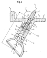
- Figs. 1, 2 and 3 show different views of an assembled State illustrated inventive pelvic endoprosthesis for replacing a pelvic part in the region of the hip joint with a base element 1, attachable to a resected iliac bone, a hip cup 6 for receiving a hip joint ball and a as Sleeve 8 formed intermediate element between the base element. 1 and hip shell 6 is arranged.
- the base member 1 is located with a flat connection surface 2 on the Resection level of the not shown resected iliac bone at.
- an anchoring pin 4 inserted in an in engages the stump stump provided hole.
- the anchoring pin 4 is opposite to an orthogonal 19 of the connecting surface 2 inclined by an angle ⁇ .
- the anchoring pin 4 is at his over the connecting surface 2 in the direction of the iliac bone formed projecting end tapered and has a longitudinally ribbed surface.
- two elbows 3 provided in a Edge region of the base member 1 are connected thereto and respectively at an angle of 90 ° from the joining surface 2 of the base member 1 protrude.
- the angle pieces 3 are each via a through hole attachable to the iliac bone.
- the base member 1 also has a likewise at an angle ⁇ of the Orthogonal 19 of the plane connecting surface 2 protruding first Approach 5, so that the inclinations of the first approach 5 and the anchoring pin 4 opposite the orthogonal 19 of the plane connecting surface 2 correspond to each other.
- the first projection 5 of the base element 1 is formed over the cylindrically shaped Sleeve 8 with a second approach 7 of the dome-shaped Hwillschale 6 connected.
- the respective center axes of the anchoring pin 4, the first approach 5, the sleeve 8 and the second approach 7 form in FIGS. 1, 2 and 3, a common center axis 9.
- Der second approach 7 is an angle ⁇ with respect to the polar axis 20th the hip cup 6 inclined.
- the sleeve 8 and the first and second lugs 5, 7 are at their each other opposite contact surfaces in each case with projections and recesses 12 provided, which are designed in the manner of a Hirth toothing, so that with respect to the center axis 9 different angular positions of the Sleeve 8 opposite the first approach 5 and the second approach 7 opposite the sleeve 8 are possible.
- FIG. 4 shows a cross section of the pelvic endoprosthesis according to the invention along the line IV-IV in Fig. 3.
- Fig. 4 omitted the representation of the projections and recesses 12.
- FIG. 4 shows that the contact surfaces of the first projection 5, the Sleeve 8 and the second projection 7 each formed approximately flat are.
- the in the assembled state of the pelvic endoprosthesis Contact planes 10, 11 defined by the contact surfaces are parallel aligned with each other.
- Fig. 4 can also be seen that in the base element 1 used anchoring pin 4 to the first approach 5 of Base member 1 extends and is screwed into the base member 1.
- a cavity is further formed, held in a still further explained in more detail ball head 14 is, which has a spherical surface over an angular range ⁇ of 200 ° and via a positive plug connection 15 to the sleeve 8 against rotation is secured.
- first approach 5 held ball head 14 engages an elongated, as a tie rod serving expansion screw 26, which is the sleeve. 8 clamped between the first approach 5 and the second approach 7. Of the not screwed into the ball head 14 of the expansion screw 26 is within the sleeve 8 or within a bore of the second approach 7 of the hip 6 arranged.
- the sleeves 8 have a clear width 25th on, which is larger than the diameter of the expansion screw 26th
- the head of the expansion screw 26 is formed as a hexagon 24 to the Screwing the expansion screw 26 held in the first approach 5 To allow ball head 14.
- the expansion screw 26 further includes a Collar 23, in the assembled state of the pelvic endoprosthesis in a cavity of the second projection 7 connected to the bore is held so that the sleeve 8 between the first lug 5 and the second approach 7 is clamped.
- the distance 13 between the base element 1 and hip shell 6 can thereby can be varied that sleeves 8 different lengths and in the Length appropriate expansion bolts 26 are provided, each between the first approach 5 and the second approach 7 can be installed or screwed are.
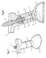
- FIGS. 5 and 6 show an embodiment of a pelvic endoprosthesis according to the invention with a cranked sleeve 8, wherein each same or corresponding parts are denoted by the same reference numerals, so that is waived on a new idea and only the deviations the embodiment shown in these figures with respect to first embodiment will be explained.
- the sleeve 8 is bent or hook-shaped bent.
- the crank 22 of the sleeve 8 has the consequence that through the contact surfaces defined contact planes 10, 11 at an acute angle ⁇ to stand by each other.
- a common center axis 27 of the anchoring pin 4 and the first approach 5 is compared to a common Center axis 28 of the expansion screw 26, most of the sleeve 8 and of the second approach 7 inclined. Due to the intervention of the expansion screw 26 is the ball head 14 shown in FIG. 6 with respect to FIG Fig. 4 tilted ball head.
- the hip shell 6 is also a dome-shaped inner shell 16 used, the two each having a shoulder 33 Shells 6, 16 connected to each other by means of a snap connection 29 are.
- the inner shell 16 encloses a particular Artificial joint ball 18 by more than 180 °. This includes the inner shell 16 a retaining ring 17, which after insertion of the joint ball 18th is connected to the inner shell 16 with this.
- FIGS. 7 and 8 show a further embodiment of a device according to the invention Pelvic endoprosthesis extending from the two above mentioned embodiments in particular by the formation of the Base element 1 is different.
- the pelvic endoprosthesis according to FIGS. 7 and 8 an angular connection surface 2.
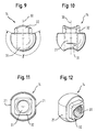
- Figs. 9, 10, 11 and 12 show different views of the above mentioned ball head 14.
- the ball head 14 has a spherical Basic form with a over an angular range ⁇ of 200 ° extending Spherical surface.
- the ball head also has a continuous, along the pole axis 30 of the ball head 14 formed threaded hole 31, in the assembled state of the pelvic endoprosthesis the expansion screw 26 engages.
- the plug-in projection 32 is substantially perpendicular to the polar axis 30 extending planes square formed, wherein in the assembled state the pelvic endoprosthesis of the male projection 32 in the corresponding shaped passage of the sleeve 8 protrudes, so that the ball head 14 is secured against rotation.
- the spherical surface of the ball head 14 has a shape in the form of a on the Pole extending band 21 trained flattening on. In perpendicular to the polar axis 30 extending planes has the ball head 14th thus a circular shape, which by two opposite, flattened Pages is broken.
- the entrance opening of the cavity of the first Approach 5 has a corresponding shape, so that in the cavity used ball head 14 in a relation to the mounting position by 90 ° rotated functional position in the first approach 5 can be kept.
- the base member 1 is attached to the resected iliac bone fastened by means of the anchoring pin 4 and the two angle pieces 3, such that the connecting surface 2 of the base element 1 on the stump stump is applied.
- the ball head 14 was already before attaching of the base member 1 at the iliac stump into the cavity of the first Approach 5 used, but may alternatively only after attachment of the base element 1 are used.
- the sleeves 8 may have different lengths and / or cranked be formed.
- the expansion screw 26 is tightened, so that the projections and recesses 12 of the contact surfaces of the first projection 5, the sleeve 8 and the second approach 7 engage each other.
- the plug-in projection 32 of the ball head 14 engages in the interior of the sleeve 8, so that secured against rotation positive connection 15 for Sleeve is formed.
- the Ball head 14 due to the engagement of the expansion screw 26 accordingly tilted (Fig. 6).
- the inner shell 16 is inserted into the hip shell 6 and secured by the snap connection 29 at this (Fig. 6).
- the joint ball 18 is inserted through the Retaining ring 17 is held in the inner shell 16, wherein the retaining ring 17 comprehensive inner shell 16, the ball joint 18 by more than 180 ° encloses.
Landscapes
- Health & Medical Sciences (AREA)
- Orthopedic Medicine & Surgery (AREA)
- Life Sciences & Earth Sciences (AREA)
- Animal Behavior & Ethology (AREA)
- General Health & Medical Sciences (AREA)
- Engineering & Computer Science (AREA)
- Biomedical Technology (AREA)
- Heart & Thoracic Surgery (AREA)
- Veterinary Medicine (AREA)
- Public Health (AREA)
- Vascular Medicine (AREA)
- Cardiology (AREA)
- Oral & Maxillofacial Surgery (AREA)
- Transplantation (AREA)
- Surgery (AREA)
- Neurology (AREA)
- Nuclear Medicine, Radiotherapy & Molecular Imaging (AREA)
- Medical Informatics (AREA)
- Molecular Biology (AREA)
- Prostheses (AREA)
Abstract
Description
Die Erfindung betrifft eine Beckenteilendoprothese mit wenigstens einem an einem reserzierten Darmbeinknochen befestigbaren Basiselement und zumindest einer in einem Abstand dazu anbringbaren Hüftschale, wobei das Basiselement einen insbesondere in einem Winkel α von der Orthogonalen einer ebenen Verbindungsfläche wegstehenden ersten Ansatz und die Hüftschale einen insbesondere von ihrer Polachse in einen Winkel β wegstehenden zweiten Ansatz aufweist.The invention relates to a pelvic endoprosthesis with at least one on a resected iliac bone fastenable base element and at least one at a distance attachable hip shell, wherein the base element one in particular at an angle α of the orthogonal a planar connecting surface wegstehende first approach and the hip shell a particular of its pole axis at an angle β has a second approach.
Es gibt Tumorpatienten, bei denen das Darmbein, d.h. der halbe Beckenknochen, um ein Drittel bis zwei Drittel seiner Höhe von unten reserziert werden muss. Ohne weitere Hilfsmaßnahmen war es früher üblich, das zugehörige Bein zu amputieren, um Komplikationen wegen fehlender Befestigung am Rumpf zu vermeiden. Um derartige Amputationen zu vermeiden, sind Beckenteilendoprothesen entwickelt worden, die nicht übermäßig belastet werden dürfen, aber zumindest eine passive Platzhalterfunktion für das daran befestigte Bein ausüben.There are tumor patients in whom the ilium, i. half the pelvic bone, resected by one third to two thirds of its height from below must become. Without further assistance, it was customary in the past associated leg amputate to complications due to missing Attachment to the hull to avoid. To such amputations too To avoid this, pelvic endoprostheses have not been developed may be overcharged, but at least a passive placeholder function exercise for the attached leg.
Eine derartige Endoprothese ist in der Patentanmeldung WO 88/01491 gezeigt, in welcher an einer Hüftschale zwei Ansätze angeformt sind, welche jeweils eine Aufnahmebohrung für einen Zapfen mit selbsthemmendem Festsitz aufweisen. Die Zapfen sind an ihrem anderen Ende jeweils am reserzierten Darmbein oder Schambein verankert. Die Verankerung am Darmbein erfolgt dabei über ein plattenförmiges Basiselement. Such an endoprosthesis is disclosed in patent application WO 88/01491 in which two lugs are formed on a hip shell, which each have a receiving bore for a pin with self-locking Have tight fit. The pins are at their other end each anchored on the resected ilium or pubis. The anchorage on the ilium takes place via a plate-shaped base element.
Eine weitere Endoprothese dieser Art ist aus der Patentanmeldung EP 0 628 294 A1 bekannt. An einem Ansatz einer Hüftschale sind Aufnahmebohrungen für Zapfen mit einem selbsthemmenden Sitz vorgesehen. Die Befestigung eines den Zapfen fortsetzenden Stielteils erfolgt durch intramedulläres Eingreifen in eine in den Darmbeinstumpf gefräste Nut. Zusätzlich ist eine mechanische Verstelleinheit vorgesehen, mit Hilfe derer das Stielteil in einem Langloch eines am Darmbein befestigten Basiselements verstellt werden kann.Another endoprosthesis of this type is known from patent application EP 0 628 294 A1 known. At a neck of a hip shell are receiving holes intended for pegs with a self-locking seat. The Fastening of a pin continuing stalk part is done by intramedullary Engaging in a groove machined in the iliac stump. additionally is a mechanical adjustment provided by means of which the stem part in a slot of a base element attached to the ilium can be adjusted.
Nachteilig an den vorstehend genannten Beckenteilendoprothesen ist jedoch, dass die Länge des Zapfens und die Winkellage des Zapfens relativ zum Basiselement und somit auch die Position und Ausrichtung der Hüftschale fest vorgegeben sind. Die Solllage der Hüftschale muss daher bereits bei der Resektion des Darmbeinknochens hinsichtlich Höhe und Richtung des Resektionsschnitts berücksichtigt werden.A disadvantage of the above-mentioned pelvic endoprostheses however, that the length of the pin and the angular position of the pin relative to the base element and thus also the position and orientation of the hip shell are fixed. The desired position of the hip shell must therefore already in the resection of the iliac bone in terms of height and Direction of resection section are taken into account.
Der Erfindung liegt daher die Aufgabe zugrunde, eine Beckenteilendoprothese der eingangs genannten Art zu schaffen, die sich durch einen möglichst einfachen Aufbau bei gleichzeitig erhöhter Flexibilität hinsichtlich der Positionierung und/oder Ausrichtung der Hüftschale auszeichnet.The invention is therefore based on the object, a pelvic endoprosthesis to create the type mentioned, by a possible simple design with increased flexibility in terms of the positioning and / or orientation of the hip.
Die Lösung dieser Aufgabe erfolgt durch die Merkmale des Anspruchs 1
und insbesondere dadurch, dass wenigstens ein separates Zwischenelement
vorgesehen ist, das zwischen dem ersten Ansatz und dem zweiten
Ansatz einbaubar ist.The solution of this object is achieved by the features of
Bei der erfindungsgemäßen Beckenteilendoprothese ist vorgesehen, dass zwischen dem Ansatz des Basiselements und dem Ansatz der Hüftschale ein weiteres Bauteil einbaubar ist. Durch die Möglichkeit, ein separates Zwischenelement einzubauen, ist eine erhöhte Flexibilität der Beckenteilendoprothese gewährleistet. Diese Flexibilität ist insbesondere dann von Vorteil, wenn der Operateur während des operativen Eingriffs Verhältnisse vorfindet, die einen von der ursprünglichen Operationsplanung abweichenden Resektionsschnitt erfordern.In the pelvic endoprosthesis according to the invention, it is provided that between the base of the base and the neck of the hip another component can be installed. By the possibility of a separate Installing intermediate element is an increased flexibility of the pelvic endoprosthesis guaranteed. This flexibility is in particular of Advantage if the surgeon during the surgical procedure ratios that deviates from the original operational planning Require resection cut.
Vorteilhafte Ausführungsformen der Erfindung sind in den Unteransprüchen, der Beschreibung sowie der Zeichnung angegeben.Advantageous embodiments of the invention are defined in the subclaims, the description and the drawing.
Vorzugsweise sind mittels des Zwischenelements unterschiedliche Relativstellungen zwischen dem Basiselement und der Hüftschale realisierbar. Dies ermöglicht insbesondere, dass auch noch nach der Verankerung des Basisteils am Darmbeinknochen unterschiedliche Stellungen der Hüftschale realisierbar sind.Preferably, by means of the intermediate element different relative positions realized between the base member and the hip cup. This allows in particular that even after the anchoring of the Base part of the iliac bone different positions of the hip shell are feasible.
Besonders vorteilhaft ist es, wenn wenigstens zwei voneinander verschiedene Zwischenelemente vorgesehen sind, die jeweils zwischen dem ersten Ansatz und dem zweiten Ansatz einbaubar sind. Die erfindungsgemäße Beckenteilendoprothese stellt hierdurch einen Baukasten unterschiedlicher Zwischenelemente bereit, die alternativ zueinander zwischen dem ersten Ansatz des Basiselements und dem zweiten Ansatz der Hüftschale einbaubar sind. Der die Beckenteilendoprothese einsetzende Operateur kann aus einem Satz voneinander verschiedener Zwischenelemente dasjenige Zwischenelement auswählen, das die für den jeweiligen Patienten günstigste Sollstellung der Hüftschale ermöglicht.It is particularly advantageous if at least two different from each other Intermediate elements are provided, each between the first Approach and the second approach are installable. The inventive Pelvic endoprosthesis thereby makes a kit different Intermediate elements ready, the alternative to each other between the first approach of the base element and the second approach of the hip shell can be installed. The surgeon who inserts the pelvic endoprosthesis can one of a set of different intermediate elements that Select the intermediate element that corresponds to the patient cheapest nominal position of the hip shell allows.
Bevorzugt sind Zwischenelemente unterschiedlicher Länge vorgesehen, so dass der Abstand zwischen dem Basiselement und der Hüftschale und somit der Abstand zwischen dem reserzierten Darmbeinstumpf und der Gelenkkugel des Oberschenkelknochens variiert werden kann. Preferably, intermediate elements of different lengths are provided, see above that the distance between the base element and the hip shell and Thus, the distance between the resected stump stump and the Joint ball of the femur can be varied.
Zusätzlich oder alternativ kann wenigstens ein Zwischenelement gekröpft sein, so dass die Mittenachsen des ersten Ansatzes und des zweiten Ansatzes gegeneinander verkippt oder parallel versetzt verlaufen können. Hierdurch werden weitere Relativstellungen zwischen dem Basiselement und der Hüftschale ermöglicht, die durch bloße Verlängerung mittels eines geraden Zwischenelements nicht realisierbar wären.Additionally or alternatively, at least one intermediate element can be cranked so that the middle axes of the first approach and the second approach tilted against each other or parallel offset. As a result, further relative positions between the base element and the hip cup made possible by mere extension by means of a straight intermediate element would not be feasible.
Ferner kann erfindungsgemäß vorgesehen sein, dass das Zwischenelement und der erste und zweite Ansatz in Kontaktflächen jeweils mit Vor- und Rücksprüngen versehen sind, die in verschiedenen Winkelstellungen einrastbar sind. Insbesondere können die Vor- und Rücksprünge in den Kontaktflächen einer Hirth-Verzahnung entsprechen. Hierdurch wird erreicht, dass insbesondere bei Verwendung eines gekröpften Zwischenelements und/oder einer bezüglich ihrer Polachse nicht rotationssymmetrisch ausgebildeten Hüftschale diese, insbesondere deren Polachse, in verschiedene Raumrichtungen orientiert werden kann, so dass wiederum weitere Relativstellungen zwischen dem Basiselement und der Hüftschale realisierbar sind. Die Vor- und Rücksprünge stellen zusätzlich eine Rotationssicherung dar.Furthermore, it can be provided according to the invention that the intermediate element and the first and second approaches in contact surfaces each with pre- and recesses are provided in different angular positions are latched. In particular, the projections and recesses in the Contact surfaces correspond to a Hirth toothing. This will achieves that, in particular when using a cranked intermediate element and / or one not rotationally symmetrical with respect to its polar axis trained hip shell this, in particular their pole axis, in different spatial directions can be oriented so that in turn further relative positions between the base element and the hip shell are feasible. The projections and recesses additionally provide a rotation lock represents.
Des Weiteren können durch Kontaktflächen definierte Kontaktebenen wenigstens eines Zwischenelements in einem von Null verschiedenen, insbesondere spitzen Winkel ε, zueinander stehen. Insbesondere können nur bei gekröpften Zwischenelementen unter einem Winkel ε zueinander stehende Kontaktebenen vorgesehen sein. Hierdurch wird ermöglicht, dass gekröpfte Zwischenelemente alternativ zu nicht gekröpften Zwischenelementen eingesetzt werden können, deren Kontaktebenen parallel zueinander verlaufen. Furthermore, contact planes defined by contact surfaces at least one intermediate element in a non-zero, in particular acute angle ε, each other. In particular, you can only with cranked intermediate elements at an angle ε to each other be provided standing contact levels. This will enable that cranked intermediate elements as an alternative to non-cranked intermediate elements can be used, the contact planes parallel to each other run.
In einem besonders bevorzugten Ausführungsbeispiel ist das Zwischenelement über einen Zuganker zwischen dem ersten und dem zweiten Ansatz verspannbar. Hierdurch kann eine besonders feste und sichere Verbindung zwischen dem Zwischenelement und dem Basiselement bzw. der Hüftschale erreicht werden. Der Zuganker kann dabei insbesondere innerhalb des jeweiligen, beispielsweise als Hülse ausgebildeten Zwischenelements geführt und die beiden Enden des Zugankers können in dem Basiselement und der Hüftschale verankert sein.In a particularly preferred embodiment, the intermediate element via a tie rod between the first and the second Clamping approach. This can be a particularly solid and secure Connection between the intermediate element and the base element or the hip cup can be achieved. The tie rod can in particular within the respective, designed as a sleeve intermediate element guided and the two ends of the tie rod can in be anchored to the base member and the hip cup.
Vorzugsweise sind zu verschieden langen Zwischenelementen in der Länge passende Zuganker vorgesehen.Preferably, the intermediate elements are of different lengths in length suitable tie rods provided.
Des Weiteren wird erfindungsgemäß vorgeschlagen, dass als Zuganker eine Dehnschraube vorgesehen ist.Furthermore, the invention proposes that as a tie rod an expansion screw is provided.
Der Zuganker kann in einen im ersten Ansatz gehaltenen Kopf eingreifen. Insbesondere kann der Kopf als Kugelgelenk ausgebildet sein. Hierdurch kann erreicht werden, dass der in dem ersten Ansatz gehaltene Kopf sowohl mit nicht gekröpften als auch mit gekröpften, insbesondere verschieden gekröpften Zwischenelementen zusammenwirken kann.The tie rod can engage in a head held in the first approach. In particular, the head may be formed as a ball joint. hereby can be achieved that the head held in the first approach both unranked and cranked, in particular different cranked intermediate elements can interact.
Es ist weiterhin bevorzugt, dass der Kopf über eine formschlüssige Steckverbindung zum Zwischenelement gegen Verdrehung gesichert ist. Dies ist insbesondere dann von Vorteil, wenn der Kopf in einer durch Drehung erreichbaren Stellung aus seiner Halterung in dem ersten Ansatz gelöst werden kann.It is further preferred that the head via a positive connection secured to the intermediate element against rotation. This is especially advantageous if the head in one by rotation achievable position released from its holder in the first approach can be.
In einer weiteren bevorzugten Ausführungsform weist der Kopf über einen Winkelbereich γ von mehr als 180°, insbesondere von mehr als 200°, eine Kugelfläche auf, die eine in Form eines sich über den Pol hinweg erstreckenden Bandes ausgebildete Abflachung besitzt, wobei der Kopf in einer gegenüber der Funktionsstellung um 90° gedrehten Montagestellung in eine im ersten Ansatz ausgebildete Kavität einsetzbar ist.In a further preferred embodiment, the head has a Angular range γ of more than 180 °, in particular more than 200 °, a Spherical surface, one in the form of a extending across the pole across Bandes has trained flattening, with the head in one opposite to the functional position rotated by 90 ° mounting position in a cavity formed in the first approach can be used.
Zur Verankerung der Beckenteilendoprothese am Darmbeinstumpf können in das Basiselement verschieden große Verankerungszapfen zur Befestigung des Basiselements am Darmbeinknochen einsetzbar sein, so dass in Abhängigkeit von den jeweiligen anatomischen Anforderungen ein passender Verankerungszapfen ausgewählt werden kann.To anchor the pelvic endoprosthesis on the iliac stump can in the base element different sized anchoring pins for Fixing the base element to be used on the iliac bone, so that depending on the particular anatomical requirements matching anchoring pin can be selected.
Des Weiteren kann in die Hüftschale eine Innenschale mit einer Schnappverbindung einsetzbar sein. Insbesondere kann in die Hüftschale eine Gelenkkugel zusammen mit einer Innenschale einsetzbar sein, welche die Gelenkkugel um mehr als 180° umschließt, so dass ein Oberschenkelknochen an der Beckenteilendoprothese befestigbar ist.Furthermore, in the hip shell an inner shell with a snap connection be usable. In particular, in the hip bowl a Joint ball can be used together with an inner shell, which the Joint ball encloses more than 180 °, leaving a thighbone attachable to the pelvic endoprosthesis.
Um eine besonders einfache und effektive Halterung der Gelenkkugel zu erreichen, kann die Innenschale einen Haltering aufweisen, der nach dem Einsetzen einer Gelenkkugel an der Hüftschale befestigbar ist.To a particularly simple and effective mounting of the ball joint reach, the inner shell may have a retaining ring, which after the Insertion of a joint ball can be fastened to the hip shell.
Als Teile eines Probierbaukastens können Basiselemente, Hüftschalen und Zwischenelemente vorgesehen sein, die jeweils aus einem sterilisierbaren Kunststoff bestehen und der Auffindung einer passenden räumlichen Stellung der Hüftschale relativ zum Basiselement dienen, wobei die Probierhüftschalen jeweils eine für eine Gelenkkugel passende Kontaktfläche aufweisen, so dass auf eine Innenschale verzichtet werden kann.As parts of a test kit basic elements, Hüftschalen and intermediate elements may be provided, each made of a sterilizable Consist of plastic and finding a suitable spatial Position of the hip cup to serve relative to the base member, wherein the Probierhüftschalen each one suitable for a ball joint contact surface have, so that can be dispensed with an inner shell.
Die Prothesenteile für Probierprothesen und für endgültig einsetzbare Prothesen können unterschiedlich gekennzeichnet sein, um möglichen Verwechslungen vorzubeugen. Die Rasterstellungen von Zwischenelementen und ersten und zweiten Ansätzen können jeweils markiert sein, so dass die mittels der aus Kunststoff bestehenden Bauteile der Beckenteilendoprothese aufgefundene passende räumliche Stellung der Hüftschale auf einfache Weise auf die endgültig einsetzbaren Prothesen übertragbar ist.The prosthesis parts for trial prostheses and for final use Prostheses may be differentially marked to be possible To prevent confusion. The grid positions of intermediate elements and first and second approaches may be marked, respectively that the means of the plastic components of the pelvic endoprosthesis found appropriate spatial position of the hip shell easily transferable to the definitive prostheses is.
Die Erfindung wird im Folgenden beispielhaft unter Bezugnahme auf die Zeichnung beschrieben. Es zeigen:
- Fig. 1 bis 3
- verschiedene Ansichten einer erfindungsgemäßen Beckenteilendoprothese mit gerader Hülse,
- Fig. 4
- einen vergrößerten Längsschnitt durch die Anordnung in Fig. 3,
- Fig. 5
- eine perspektivische Ansicht einer erfindungsgemäßen Beckenteilendoprothese mit gekröpfter Hülse,
- Fig. 6
- einen vergrößerten Längsschnitt durch die Anordnung in Fig. 5 mit eingesetzter Innenschale und Gelenkkugel,
- Fig. 7
- eine perspektivische Ansicht einer erfindungsgemäßen Beckenteilendoprothese mit gerader Hülse und einer winkelförmigen, direkt am Sakrum ansetzbaren Verbindungsfläche,
- Fig. 8
- einen vergrößerten Längsschnitt durch die Anordnung in Fig. 7, und
- Fig. 9
bis 12 - verschiedene Ansichten eines Kugelgelenks einer erfindungsgemäßen Beckenteilendoprothese.
- Fig. 1 to 3
- various views of a straight sleeve pelvic endoprosthesis according to the invention,
- Fig. 4
- an enlarged longitudinal section through the arrangement in Fig. 3,
- Fig. 5
- 3 is a perspective view of a pelvic pelvic pelvic prosthesis according to the invention;
- Fig. 6
- an enlarged longitudinal section through the arrangement in Figure 5 with inserted inner shell and ball joint,
- Fig. 7
- a perspective view of a pelvic endoprosthesis according to the invention with a straight sleeve and an angular, directly attachable to the sacrificial joint surface,
- Fig. 8
- an enlarged longitudinal section through the arrangement in Fig. 7, and
- Fig. 9 to 12
- various views of a ball joint of a Beckenenteilendoprothese invention.
Die Fig. 1, 2 und 3 zeigen verschiedene Ansichten einer im zusammengesetzten
Zustand dargestellten erfindungsgemäßen Beckenteilendoprothese
zum Ersatz eines Beckenteils im Bereich des Hüftgelenks mit einem Basiselement
1, das an einem reserzierten Darmbeinknochen befestigbar ist,
einer Hüftschale 6 zur Aufnahme einer Hüftgelenkkugel und einem als
Hülse 8 ausgebildeten Zwischenelement, das zwischen Basiselement 1
und Hüftschale 6 angeordnet ist.Figs. 1, 2 and 3 show different views of an assembled
State illustrated inventive pelvic endoprosthesis
for replacing a pelvic part in the region of the hip joint with a
Das Basiselement 1 liegt mit einer ebenen Verbindungsfläche 2 an der
Resektionsebene des nicht dargestellten reserzierten Darmbeinknochens
an. Zur Befestigung des Basiselements 1 an dem Darmbeinknochen ist in
das Basiselement 1 ein Verankerungszapfen 4 eingesetzt, der in eine in
dem Darmbeinstumpf vorgesehene Bohrung eingreift.The
Der Verankerungszapfen 4 ist gegenüber einer Orthogonalen 19 der Verbindungsfläche
2 um einen Winkel α geneigt. Der Verankerungszapfen 4
ist an seinem über die Verbindungsfläche 2 in Richtung des Darmbeinknochens
vorstehenden Ende konisch zulaufend ausgebildet und weist
eine längsgerippte Oberfläche auf.The
Neben dem Verankerungszapfen 4 sind zur Befestigung des Basiselements
1 am Darmbeinknochen zwei Winkelstücke 3 vorgesehen, die in einem
Randbereich des Basiselements 1 mit diesem verbunden sind und jeweils
in einem Winkel von 90° von der Verbindungsfläche 2 des Basiselements 1
abstehen. Die Winkelstücke 3 sind jeweils über eine Durchgangsbohrung
am Darmbeinknochen befestigbar. In addition to the
Das Basiselement 1 weist ferner einen ebenfalls im Winkel α von der
Orthogonalen 19 der ebenen Verbindungsfläche 2 wegstehenden ersten
Ansatz 5 auf, so dass die Neigungen des ersten Ansatzes 5 und des Verankerungszapfens
4 gegenüber der Orthogonalen 19 der ebenen Verbindungsfläche
2 einander entsprechen.The
Der erste Ansatz 5 des Basiselements 1 ist über die zylinderförmig ausgebildete
Hülse 8 mit einem zweiten Ansatz 7 der kalottenförmig ausgebildeten
Hüftschale 6 verbunden. Die jeweiligen Mittenachsen des Verankerungszapfens
4, des ersten Ansatzes 5, der Hülse 8 und des zweiten Ansatzes
7 bilden in den Fig. 1, 2 und 3 eine gemeinsame Mittenachse 9. Der
zweite Ansatz 7 ist dabei um einen Winkel β gegenüber der Polachse 20
der Hüftschale 6 geneigt.The
Die Hülse 8 und der erste und zweite Ansatz 5, 7 sind an ihren einander
gegenüberliegenden Kontaktflächen jeweils mit Vor- und Rücksprüngen
12 versehen, die nach Art einer Hirth-Verzahnung ausgeführt sind, so
dass bezüglich der Mittenachse 9 verschiedene Winkelstellungen der
Hülse 8 gegenüber dem ersten Ansatz 5 und des zweiten Ansatzes 7 gegenüber
der Hülse 8 möglich sind.The
Fig. 4 zeigt einen Querschnitt der erfindungsgemäßen Beckenteilendoprothese
entlang der Linie IV-IV in Fig. 3. Der Einfachheit halber wurde in
Fig. 4 auf die Darstellung der Vor- und Rücksprünge 12 verzichtet. Aus
Fig. 4 ist ersichtlich, dass die Kontaktflächen des ersten Ansatzes 5, der
Hülse 8 und des zweiten Ansatzes 7 jeweils annähernd eben ausgebildet
sind. Die im zusammengesetzten Zustand der Beckenteilendoprothese
durch die Kontaktflächen definierten Kontaktebenen 10, 11 sind parallel
zueinander ausgerichtet. 4 shows a cross section of the pelvic endoprosthesis according to the invention
along the line IV-IV in Fig. 3. For the sake of simplicity, in
Fig. 4 omitted the representation of the projections and recesses 12. Out
FIG. 4 shows that the contact surfaces of the
Fig. 4 kann weiterhin entnommen werden, dass sich der in das Basiselement
1 eingesetzte Verankerungszapfen 4 bis in den ersten Ansatz 5 des
Basiselements 1 erstreckt und in das Basiselement 1 eingeschraubt ist.
Im ersten Ansatz 5 des Basiselements 1 ist ferner eine Kavität ausgebildet,
in der ein an anderer Stelle noch näher erläuterter Kugelkopf 14 gehalten
ist, der über einen Winkelbereich γ von 200° eine Kugelfläche aufweist und
über eine formschlüssige Steckverbindung 15 zur Hülse 8 gegen Verdrehung
gesichert ist.Fig. 4 can also be seen that in the
In den im ersten Ansatz 5 gehaltenen Kugelkopf 14 greift eine lang gestreckte,
als Zuganker dienende Dehnschraube 26 ein, die die Hülse 8
zwischen dem ersten Ansatz 5 und dem zweiten Ansatz 7 verspannt. Der
nicht in den Kugelkopf 14 eingeschraubte Teil der Dehnschraube 26 ist
innerhalb der Hülse 8 bzw. innerhalb einer Bohrung des zweiten Ansatzes
7 der Hüftschale 6 angeordnet. Die Hülsen 8 weisen eine lichte Weite 25
auf, die größer ist als der Durchmesser der Dehnschraube 26.In the
Der Kopf der Dehnschraube 26 ist als Sechskant 24 ausgebildet, um das
Einschrauben der Dehnschraube 26 in den im ersten Ansatz 5 gehaltenen
Kugelkopf 14 zu ermöglichen. Die Dehnschraube 26 umfasst ferner einen
Kragen 23, der im zusammengesetzten Zustand der Beckenteilendoprothese
in einer mit der Bohrung verbundenen Kavität des zweiten Ansatzes 7
gehalten wird, so dass die Hülse 8 zwischen dem ersten Ansatz 5 und dem
zweiten Ansatz 7 verspannbar ist.The head of the
Der Abstand 13 zwischen Basiselement 1 und Hüftschale 6 kann dadurch
variiert werden, dass Hülsen 8 unterschiedlicher Länge und dazu in der
Länge passende Dehnschrauben 26 vorgesehen sind, die jeweils zwischen
dem ersten Ansatz 5 und dem zweiten Ansatz 7 einbaubar bzw. einschraubbar
sind. The
Die Fig. 5 und 6 zeigen eine Ausbildung einer erfindungsgemäßen Beckenteilendoprothese
mit einer gekröpften Hülse 8, wobei jeweils gleiche oder
entsprechende Teile mit denselben Bezugszeichen bezeichnet sind, so dass
auf eine erneute Vorstellung verzichtet wird und lediglich die Abweichungen
der in diesen Figuren dargestellten Ausführungsform gegenüber der
ersten Ausführungsform erläutert werden.FIGS. 5 and 6 show an embodiment of a pelvic endoprosthesis according to the invention
with a cranked
Gemäß den Fig. 5 und 6 ist die Hülse 8 gekröpft bzw. hakenförmig gebogen.
Die Kröpfung 22 der Hülse 8 hat zur Folge, dass die durch die Kontaktflächen
definierten Kontaktebenen 10, 11 in einem spitzen Winkel ε
zueinander stehen. Eine gemeinsame Mittenachse 27 des Verankerungszapfens
4 und des ersten Ansatzes 5 ist gegenüber einer gemeinsamen
Mittenachse 28 der Dehnschraube 26, des größten Teils der Hülse 8 und
des zweiten Ansatzes 7 geneigt. Aufgrund des Eingreifens der Dehnschraube
26 ist der in Fig. 6 dargestellte Kugelkopf 14 gegenüber dem in
Fig. 4 gezeigten Kugelkopf verkippt.According to FIGS. 5 and 6, the
In die Hüftschale 6 ist eine ebenfalls kalottenförmig ausgebildete Innenschale
16 eingesetzt, wobei die beiden jeweils eine Schulter 33 aufweisenden
Schalen 6, 16 mittels einer Schnappverbindung 29 miteinander verbunden
sind. Die Innenschale 16 umschließt dabei eine insbesondere
künstliche Gelenkkugel 18 um mehr als 180°. Dazu umfasst die Innenschale
16 einen Haltering 17, der nach dem Einsetzen der Gelenkkugel 18
in die Innenschale 16 mit dieser verbunden wird.In the
Um eine korrekte Relativpositionierung der Innenschale 16 bezüglich der
Hüftschale 6 zu gewährleisten, weist die Innenschale 16 in ihrem Polbereich
eine in Richtung der Hüftschale 6 vorstehende Nase 34 auf, die im
zusammengesetzten Zustand der Beckenteilendoprothese in eine die
Kavität des zweiten Ansatzes 7 fortsetzende Ausnehmung der Hüftschale 6
eingreift.To a correct relative positioning of the
Die Fig. 7 und 8 zeigen eine weitere Ausführungsform einer erfindungsgemäßen
Beckenteilendoprothese, die sich von den beiden vorstehend
genannten Ausführungsformen insbesondere durch die Ausbildung des
Basiselements 1 unterscheidet. Um ein Ansetzen direkt am Sakrum zu
ermöglichen, weist die Beckenteilendoprothese gemäß den Fig. 7 und 8
eine winkelförmige Verbindungsfläche 2 auf.FIGS. 7 and 8 show a further embodiment of a device according to the invention
Pelvic endoprosthesis extending from the two above
mentioned embodiments in particular by the formation of the
Die Fig. 9, 10, 11 und 12 zeigen verschiedene Ansichten des bereits vorstehend
erwähnten Kugelkopfs 14. Der Kugelkopf 14 weist eine kugelige
Grundform mit einer sich über einen Winkelbereich γ von 200° erstreckenden
Kugelfläche auf. Der Kugelkopf weist weiterhin eine durchgehende,
entlang der Polachse 30 des Kugelkopfs 14 ausgebildete Gewindebohrung
31 auf, in die im zusammengesetzten Zustand der Beckenteilendoprothese
die Dehnschraube 26 eingreift.Figs. 9, 10, 11 and 12 show different views of the above
mentioned
An der dem Pol abgewandten Seite des Kugelkopfs 14 ist ein von der
Bohrung 31 durchsetzter Steckvorsprung 32 ausgebildet. Der Steckvorsprung
32 ist in senkrecht zur Polachse 30 verlaufenden Ebenen im Wesentlichen
quadratisch ausgebildet, wobei im zusammengesetzten Zustand
der Beckenteilendoprothese der Steckvorsprung 32 in den entsprechend
geformten Durchgang der Hülse 8 hineinragt, so dass der Kugelkopf
14 gegen Verdrehung gesichert ist.At the side facing away from the pole of the
Die Kugelfläche des Kugelkopfs 14 weist eine in Form eines sich über den
Pol hinweg erstreckendes Bandes 21 ausgebildete Abflachung auf. In
senkrecht zur Polachse 30 verlaufenden Ebenen besitzt der Kugelkopf 14
somit eine kreisrunde Form, die durch zwei gegenüberliegende, abgeflachte
Seiten unterbrochen ist. Die Eingangsöffnung der Kavität des ersten
Ansatzes 5 weist eine entsprechende Form auf, so dass der in die Kavität
eingesetzte Kugelkopf 14 in einer gegenüber der Montagestellung um 90°
gedrehten Funktionsstellung im ersten Ansatz 5 gehalten werden kann.The spherical surface of the
Nachfolgend wird der Zusammenbau einer erfindungsgemäßen Beckenteilendoprothese unter Bezugnahme auf die Figuren beschrieben.The following is the assembly of a pelvic endoprosthesis according to the invention described with reference to the figures.
Zunächst wird das Basiselement 1 an dem reserzierten Darmbeinknochen
mittels des Verankerungszapfens 4 und der beiden Winkelstücke 3 befestigt,
so dass die Verbindungsfläche 2 des Basiselements 1 an dem Darmbeinstumpf
anliegt. Der Kugelkopf 14 wurde bereits vor dem Anbringen
des Basiselements 1 an dem Darmbeinstumpf in die Kavität des ersten
Ansatzes 5 eingesetzt, kann alternativ aber auch erst nach dem Anbringen
des Basiselements 1 eingesetzt werden.First, the
Danach wählt der Operateur aus einem Satz voneinander verschiedener
Hülsen 8, die unterschiedliche Relativstellungen zwischen dem Basiselement
1 und der Hüftschale 6 ermöglichen, diejenige Hülse 8 aus, die die
unter anatomischen Gesichtspunkten zweckmäßigste Relativstellung
bewirkt. Die Hülsen 8 können unterschiedliche Längen aufweisen
und/oder gekröpft ausgebildet sein.Thereafter, the surgeon selects from a set of different from each
Anschließend wird eine zu der Länge der ausgewählten Hülse 8 passende
Dehnschraube 26 aus einem Satz unterschiedlich langer Dehnschrauben
ausgewählt. Dann wird die Dehnschraube 26 durch die im zweiten Ansatz
7 der Hüftschale 6 ausgebildete Bohrung und durch die Hülse 8 hindurchgeführt
und in die Bohrung 31 des im ersten Ansatz 5 gehaltenen
Kugelkopfs 14 eingeschraubt. Subsequently, a matching to the length of the selected
Unter Berücksichtigung der Orientierung der Hüftschale 6 und ggf. der
Kröpfung 22 der Hülse 8 wird die Dehnschraube 26 festgezogen, so dass
die Vor- und Rücksprünge 12 der Kontaktflächen des ersten Ansatzes 5,
der Hülse 8 und des zweiten Ansatzes 7 ineinander greifen. Der Steckvorsprung
32 des Kugelkopfs 14 greift in das Innere der Hülse 8 ein, so dass
eine gegen Verdrehung gesicherte formschlüssige Steckverbindung 15 zur
Hülse gebildet wird. Bei Verwendung einer gekröpften Hülse 8 wird der
Kugelkopf 14 aufgrund des Eingreifens der Dehnschraube 26 entsprechend
verkippt (Fig. 6).Taking into account the orientation of the
Schließlich wird die Innenschale 16 in die Hüftschale 6 eingesetzt und
mittels der Schnappverbindung 29 an dieser befestigt (Fig. 6). Zuvor wurde
in die Innenschale 16 die Gelenkkugel 18 eingesetzt, die durch den
Haltering 17 in der Innenschale 16 gehalten ist, wobei die den Haltering
17 umfassende Innenschale 16 die Gelenkkugel 18 um mehr als 180°
umschließt.Finally, the
Aufgrund der zur Verfügung stehenden, insbesondere verschieden langen
und/oder gekröpften Zwischenelemente 8 besitzt eine erfindungsgemäße
Beckenteilendoprothese eine erhöhte Flexibilität hinsichtlich der Positionierung
und Ausrichtung der Hüftschale 6, so dass bei einem operativen
Eingriff die jeweils aus anatomischen Gründen zweckmässigste Relativstellung
zwischen Basiselement 1 und Hüftschlale 6 erreicht werden
kann. Insbesondere werden dem Operateur größere Gestaltungsfreiheiten
beim Setzen des Resektionsschnitts am Darmbeinknochen ermöglicht. Due to the available, especially different lengths
and / or cranked
- 11
- Basiselementbase element
- 22
- Verbindungsflächeinterface
- 33
- Winkelstückelbow
- 44
- Verankerungszapfenanchoring pin
- 55
- erster Ansatzfirst approach
- 66
- Hüftschalehip shell
- 77
- zweiter Ansatzsecond approach
- 88th
- Hülseshell
- 99
- Mittenachsemid-axis
- 1010
- KontaktebeneContact level
- 1111
- KontaktebeneContact level
- 1212
- Vor- und RücksprüngeProjections and recesses
- 1313
- Abstanddistance
- 1414
- Kugelkopfball head
- 1515
- Steckverbindungconnector
- 1616
- Innenschaleinner shell
- 1717
- Halteringretaining ring
- 1818
- Gelenkkugeljoint ball
- 1919
- Orthogonaleorthogonal
- 2020
- Polachsepolar axis
- 2121
- Bandtape
- 2222
- Kröpfungcranking
- 2323
- Kragencollar
- 2424
- Sechskanthexagon
- 2525
- lichte Weiteclear width
- 2626
- Dehnschraubejackscrew
- 2727
- Mittenachse mid-axis
- 2828
- Mittenachsemid-axis
- 2929
- Schnappverbindungsnap
- 3030
- Polachsepolar axis
- 3131
- Bohrungdrilling
- 3232
- Steckvorsprungplug projection
- 3333
- Schultershoulder
- 3434
- Nasenose
- αα
- Winkelangle
- ββ
- Winkelangle
- γγ
- Winkelangle
- εε
- Winkelangle
Claims (22)
dadurch gekennzeichnet, dass wenigstens ein separates Zwischenelement (8) vorgesehen ist, das zwischen dem ersten Ansatz (5) und dem zweiten Ansatz (7) einbaubar ist.A pelvic endoprosthesis having at least one base element (1) which can be fastened to a resected iliac bone and at least one hip shell (6) which can be attached at a distance (13), the base element (1) projecting in particular at an angle α from the orthogonal (19) of a planar connecting surface (2) projecting first projection (5) and the hip shell (6) has a second projection (7) protruding in particular from its pole axis (20) at an angle β,
characterized in that at least one separate intermediate element (8) is provided which can be installed between the first projection (5) and the second projection (7).
dadurch gekennzeichnet, dass mittels des Zwischenelements (8) unterschiedliche Relativstellungen zwischen dem Basislement (1) und der Hüftschale (6) realisierbar sind.A pelvic endoprosthesis according to claim 1,
characterized in that by means of the intermediate element (8) different relative positions between the base element (1) and the hip shell (6) can be realized.
dadurch gekennzeichnet, dass wenigstens zwei voneinander verschiedene Zwischenelemente (8) vorgesehen sind, die jeweils zwischen dem ersten Ansatz (5) und dem zweiten Ansatz (7) einbaubar sind.A pelvic endoprosthesis according to claim 1 or 2,
characterized in that at least two mutually different intermediate elements (8) are provided, each between the first projection (5) and the second projection (7) can be installed.
dadurch gekennzeichnet, dass Zwischenelemente (8) unterschiedlicher Länge vorgesehen sind.A pelvic endoprosthesis according to any one of claims 1 to 3,
characterized in that intermediate elements (8) of different lengths are provided.
dadurch gekennzeichnet, dass wenigstens ein Zwischenelement (8) gekröpft ist.A pelvic endoprosthesis according to any one of claims 1 to 4,
characterized in that at least one intermediate element (8) is cranked.
dadurch gekennzeichnet, dass das Zwischenelement (8) und der erste und zweite Ansatz (5, 7) in Kontaktflächen jeweils mit Vor- und Rücksprüngen (12) versehen sind, die in verschiedenen Winkelstellungen einrastbar sind.A pelvic endoprosthesis according to any one of claims 1 to 5,
characterized in that the intermediate element (8) and the first and second lugs (5, 7) are provided in contact surfaces each with projections and recesses (12) which can be latched in different angular positions.
dadurch gekennzeichnet, dass die Vor- und Rücksprünge (12) in den Kontaktflächen einer Hirth-Verzahnung entsprechen.A pelvic endoprosthesis according to claim 6,
characterized in that the projections and recesses (12) correspond in the contact surfaces of a Hirth toothing.
dadurch gekennzeichnet, dass durch Kontaktflächen definierte Kontaktebenen (10, 11) wenigstens eines Zwischenelements (8) in einem von Null verschiedenen, insbesondere spitzen Winkel ε, zueinander stehen. A pelvic endoprosthesis according to any one of claims 1 to 7,
characterized in that by contact surfaces defined contact planes (10, 11) of at least one intermediate element (8) in a nonzero, in particular acute angle ε, to each other.
dadurch gekennzeichnet, dass das Zwischenelement (8) über einen Zuganker (9) zwischen dem ersten und dem zweiten Ansatz (5, 7) verspannbar ist.A pelvic endoprosthesis according to any one of claims 1 to 8,
characterized in that the intermediate element (8) via a tie rod (9) between the first and the second projection (5, 7) is clamped.
dadurch gekennzeichnet, dass zu verschieden langen Zwischenelementen (8) in der Länge passende Zuganker (9) vorgesehen sind.A pelvic endoprosthesis according to claim 9,
characterized in that to different length intermediate elements (8) in the length suitable tie rods (9) are provided.
dadurch gekennzeichnet, dass als Zuganker (9) eine Dehnschraube (26) vorgesehen ist.A pelvic endoprosthesis according to claim 9 or 10,
characterized in that a tension screw (26) is provided as the tie rod (9).
dadurch gekennzeichnet, dass der Zuganker (9) in einen im ersten Ansatz (5) gehaltenen Kopf (14) eingreift.A pelvic endoprosthesis according to any one of claims 9 to 11,
characterized in that the tie rod (9) engages in a in the first approach (5) held head (14).
dadurch gekennzeichnet, dass der Kopf als Kugelgelenk (14) ausgebildet ist.A pelvic endoprosthesis according to claim 12,
characterized in that the head is designed as a ball joint (14).
dadurch gekennzeichnet, dass der Kopf (14) über eine formschlüssige Steckverbindung (15) zum Zwischenelement (8) gegen Verdrehung gesichert ist. A pelvic endoprosthesis according to claim 12 or 13,
characterized in that the head (14) via a positive plug connection (15) to the intermediate element (8) is secured against rotation.
dadurch gekennzeichnet, dass der Kopf (14) über einen Winkelbereich γ von mehr als 180°, insbesondere von mehr als 200°, eine Kugelfläche aufweist, die eine in Form eines sich über den Pol hinweg erstreckenden Bandes (21) ausgebildete Abflachung besitzt, wobei der Kopf (14) in einer gegenüber der Funktionsstellung um 90° gedrehten Montagestellung in eine im ersten Ansatz (5) ausgebildete Kavität einsetzbar ist.A pelvic endoprosthesis according to any one of claims 12 to 14,
characterized in that the head (14) over an angular range γ of more than 180 °, in particular of more than 200 °, a spherical surface having a in the form of a over the pole away extending band (21) formed flattening, wherein the head (14) can be inserted in a mounting position rotated by 90 ° relative to the functional position into a cavity formed in the first projection (5).
dadurch gekennzeichnet, dass in das Basiselement (1) verschieden große Verankerungszapfen (4) zur Befestigung des Basiselements (1) am Darmbeinknochen einsetzbar sind.A pelvic endoprosthesis according to any one of claims 1 to 15,
characterized in that in the base element (1) different sized anchoring pins (4) for attachment of the base member (1) are used on the iliac bone.
dadurch gekennzeichnet, dass in die Hüftschale (6) eine Innenschale (16) mit einer Schnappverbindung (29) einsetzbar ist.A pelvic endoprosthesis according to any one of claims 1 to 16,
characterized in that in the hip shell (6), an inner shell (16) with a snap connection (29) can be inserted.
dadurch gekennzeichnet, dass in die Hüftschale (6) eine Gelenkkugel (18) zusammen mit einer Innenschale (16) einsetzbar ist, welche die Gelenkkugel (18) um mehr als 180° umschließt. A pelvic endoprosthesis according to any one of claims 1 to 17,
characterized in that in the hip shell (6) a joint ball (18) together with an inner shell (16) can be inserted, which surrounds the joint ball (18) by more than 180 °.
dadurch gekennzeichnet, dass die Innenschale (16) einen Haltering (17) aufweist, der nach dem Einsetzen einer Gelenkkugel (18) an der Hüftschale (6) befestigbar ist.A pelvic endoprosthesis according to claim 17 or 18,
characterized in that the inner shell (16) has a retaining ring (17) which can be fastened to the hip shell (6) after the insertion of a joint ball (18).
dadurch gekennzeichnet, dass als Teile eines Probierbaukastens Basiselemente, Hüftschalen und Zwischenelemente vorgesehen sind, die jeweils aus einem sterilisierbaren Kunststoff bestehen und der Auffindung einer passenden räumlichen Stellung der Hüftschale relativ zum Basiselement dienen, wobei die Probierhüftschalen jeweils eine für eine Gelenkkugel passende Kontaktfläche aufweisen.A pelvic endoprosthesis according to any one of claims 1 to 19,
characterized in that provided as parts of a Probierbaukastens base elements, Hüftschalen and intermediate elements, each consisting of a sterilizable plastic and the finding of a suitable spatial position of the hip cup relative to the base member, wherein the Probierhüftschalen each have a suitable for a joint ball contact surface.
dadurch gekennzeichnet, dass die Prothesenteile für Probierprothesen und für endgültig einsetzbare Prothesen (1, 6, 8) unterschiedlich gekennzeichnet sind.A pelvic endoprosthesis according to claim 20,
characterized in that the prosthesis parts for trial prostheses and for definitive prostheses (1, 6, 8) are marked differently.
dadurch gekennzeichnet, dass die Rasterstellungen von Zwischenelementen (8) und ersten und zweiten Ansätzen (5, 7) jeweils markiert sind.A pelvic endoprosthesis according to claim 20 or 21,
characterized in that the grid positions of intermediate elements (8) and first and second lugs (5, 7) are each marked.
Priority Applications (5)
| Application Number | Priority Date | Filing Date | Title |
|---|---|---|---|
| DE502004002530T DE502004002530D1 (en) | 2004-02-25 | 2004-02-25 | pelvic endoprosthesis |
| EP04004256A EP1570810B1 (en) | 2004-02-25 | 2004-02-25 | Partial pelvic endoprothesis |
| ES04004256T ES2276180T3 (en) | 2004-02-25 | 2004-02-25 | PARTIAL ENDOPROTESIS OF PELVIS. |
| AT04004256T ATE349978T1 (en) | 2004-02-25 | 2004-02-25 | PELVIC PART PROSTHESIS |
| US11/046,462 US7635391B2 (en) | 2004-02-25 | 2005-01-28 | Endoprosthesis for part of the pelvis |
Applications Claiming Priority (1)
| Application Number | Priority Date | Filing Date | Title |
|---|---|---|---|
| EP04004256A EP1570810B1 (en) | 2004-02-25 | 2004-02-25 | Partial pelvic endoprothesis |
Publications (2)
| Publication Number | Publication Date |
|---|---|
| EP1570810A1 true EP1570810A1 (en) | 2005-09-07 |
| EP1570810B1 EP1570810B1 (en) | 2007-01-03 |
Family
ID=34745888
Family Applications (1)
| Application Number | Title | Priority Date | Filing Date |
|---|---|---|---|
| EP04004256A Expired - Lifetime EP1570810B1 (en) | 2004-02-25 | 2004-02-25 | Partial pelvic endoprothesis |
Country Status (5)
| Country | Link |
|---|---|
| US (1) | US7635391B2 (en) |
| EP (1) | EP1570810B1 (en) |
| AT (1) | ATE349978T1 (en) |
| DE (1) | DE502004002530D1 (en) |
| ES (1) | ES2276180T3 (en) |
Families Citing this family (21)
| Publication number | Priority date | Publication date | Assignee | Title |
|---|---|---|---|---|
| US7344565B2 (en) * | 2003-02-04 | 2008-03-18 | Wright Medical Technology, Inc. | Acetabular component insertion and extraction tool for use therewith, and method of locking an acetabular component to an insertion and extraction tool |
| US8419798B2 (en) * | 2003-12-30 | 2013-04-16 | Depuy Products, Inc. | Joint prosthesis with infinitely positionable head |
| US8273093B2 (en) * | 2004-06-29 | 2012-09-25 | Depuy Products, Inc. | Instrumentation for recording and replicating orthopaedic implant orientation |
| US8460390B2 (en) * | 2004-12-29 | 2013-06-11 | Depuy Products, Inc. | System and method for replicating orthopaedic implant orientation |
| US8444698B2 (en) | 2004-12-29 | 2013-05-21 | Depuy Products, Inc. | Joint prosthesis with infinitely positionable head |
| US8679185B2 (en) | 2005-09-30 | 2014-03-25 | DePuy Synthes Products, LLC | Joint prosthesis with positionable head |
| WO2007114841A1 (en) * | 2006-04-04 | 2007-10-11 | Smith & Nephew, Inc. | Trial coupler systems and methods |
| US8187280B2 (en) | 2007-10-10 | 2012-05-29 | Biomet Manufacturing Corp. | Knee joint prosthesis system and method for implantation |
| CN101646403B (en) | 2007-01-10 | 2013-03-20 | 拜欧米特制造公司 | Knee joint prosthesis system for implantation |
| US8328873B2 (en) | 2007-01-10 | 2012-12-11 | Biomet Manufacturing Corp. | Knee joint prosthesis system and method for implantation |
| US8163028B2 (en) | 2007-01-10 | 2012-04-24 | Biomet Manufacturing Corp. | Knee joint prosthesis system and method for implantation |
| US8562616B2 (en) | 2007-10-10 | 2013-10-22 | Biomet Manufacturing, Llc | Knee joint prosthesis system and method for implantation |
| US8002838B2 (en) * | 2008-06-11 | 2011-08-23 | Depuy Products, Inc. | Joint prosthesis with positionable head |
| BRPI0923222A2 (en) * | 2008-12-02 | 2017-06-06 | Smith & Nephew Inc | methods and apparatus for acetabulum arthroplasty |
| US9101479B2 (en) * | 2013-03-15 | 2015-08-11 | Depuy (Ireland) | Prosthetic components and methods for joint line access |
| US20140277530A1 (en) | 2013-03-15 | 2014-09-18 | Smed-Ta/Td, Llc | Fixation of bone implants |
| US10806589B2 (en) | 2016-07-08 | 2020-10-20 | Beijing AK Medical Co., Ltd. | Hipbone prosthesis |
| US10751186B2 (en) | 2017-09-12 | 2020-08-25 | Zimmer, Inc. | Methods for attaching acetabular augments together or to acetabular shells |
| EP3498230B1 (en) * | 2017-12-15 | 2020-10-28 | Waldemar Link GmbH & Co. KG | Modular endoprosthesis shaft system with rotating element |
| CN109259899A (en) * | 2018-11-14 | 2019-01-25 | 广州华钛三维材料制造有限公司 | Rumpbone and symphysis pelvis prosthese |
| CN111000664A (en) * | 2019-12-09 | 2020-04-14 | 北京力达康科技有限公司 | Biological coating hip joint prosthesis |
Citations (4)
| Publication number | Priority date | Publication date | Assignee | Title |
|---|---|---|---|---|
| DE4133433C1 (en) * | 1991-10-09 | 1993-05-19 | S + G Implants Gmbh, 2400 Luebeck, De | Hip region pelvic joint prosthesis - has through bores in metal outer shell and coacting intermediate member for anchoring |
| EP0628294A1 (en) * | 1993-06-08 | 1994-12-14 | ESKA Implants GmbH & Co. | Partial pelvic endoprothesis |
| US5507825A (en) * | 1993-04-15 | 1996-04-16 | Sulzer Medizinaltechnik Ag | Kit for an artificial joint socket, in particular a hipjoint socket |
| US5916268A (en) * | 1992-01-29 | 1999-06-29 | Sulzer Medizinaltechnik Ag | Kit for an artificial acetabulum |
Family Cites Families (35)
| Publication number | Priority date | Publication date | Assignee | Title |
|---|---|---|---|---|
| US2641461A (en) * | 1951-05-17 | 1953-06-09 | Crucible Steel Corp | Bessemer converter |
| US3685058A (en) * | 1970-10-19 | 1972-08-22 | Raymond G Tronzo | Hip prosthesis |
| US3740769A (en) * | 1971-02-11 | 1973-06-26 | E Haboush | Prosthesis for hip joints |
| US3840904A (en) * | 1973-04-30 | 1974-10-15 | R Tronzo | Acetabular cup prosthesis |
| US3903549A (en) * | 1974-06-12 | 1975-09-09 | William Minor Deyerle | Acetabular cup prosthesis component for total or subtotal hip prosthesis system |
| US4380090B1 (en) * | 1981-07-24 | 1993-09-21 | A. Ramos Pedro | Hip prosthesis |
| US4623352A (en) * | 1982-01-18 | 1986-11-18 | Indong Oh | Protrusio cup |
| US4955919A (en) * | 1983-05-06 | 1990-09-11 | Pappas Michael J | Multi-component joint prosthesis with increased wall flexibility facilitating component assembly |
| US4662891A (en) * | 1983-11-21 | 1987-05-05 | Joint Medical Products Corporation | Fixation elements for artificial joints |
| FR2584603B1 (en) * | 1985-07-09 | 1990-03-30 | Brunet Jean Louis | PERFECTED HIP PROSTHESIS |
| US4822370A (en) * | 1986-01-14 | 1989-04-18 | Orthoplant Endoprothetik | Hip joint femoral prosthesis |
| DE3629799A1 (en) | 1986-09-02 | 1988-03-03 | S & G Implants Gmbh | ENDOPROTHESIS FOR THE REPLACEMENT OF A POOL PART IN THE AREA OF THE HIP JOINT |
| EP0265712A1 (en) * | 1986-10-16 | 1988-05-04 | Protek AG | Acetabular component for a total hip prosthesis |
| DE8714635U1 (en) * | 1987-11-03 | 1987-12-17 | Waldemar Link Gmbh & Co, 2000 Hamburg, De | |
| GB9000124D0 (en) * | 1990-01-04 | 1990-03-07 | Howmedica | Prosthetic bearing assembly |
| US5176711A (en) * | 1991-03-06 | 1993-01-05 | Grimes James B | Acetabular revision system |
| US5192329A (en) * | 1991-03-07 | 1993-03-09 | Joint Medical Products Corporation | Oblong acetabular cup |
| ATE146668T1 (en) * | 1992-04-03 | 1997-01-15 | Sulzer Orthopaedie Ag | OUTER SHELL FOR AN ARTIFICIAL HIP JOINT |
| US5326368A (en) * | 1992-09-22 | 1994-07-05 | Howmedica, Inc. | Modular acetabular cup |
| DE59208435D1 (en) * | 1992-10-07 | 1997-06-05 | Osteo Ag | Acetabular cup support ring |
| DE4438620A1 (en) * | 1994-05-02 | 1995-11-09 | Laghaollah Dr Elhami | Joint prosthesis and device for making a bore in at least one joint head |
| DE59410011D1 (en) * | 1994-06-15 | 2002-01-24 | Sulzer Orthopaedie Ag Baar | Artificial acetabular cup |
| US5702477A (en) * | 1996-05-09 | 1997-12-30 | Osteonics Corp. | Acetabular shell with supplemental support and method |
| US5871548A (en) * | 1996-12-07 | 1999-02-16 | Johnson & Johnson Professional, Inc. | Modular acetabular reinforcement system |
| US5976149A (en) * | 1997-02-11 | 1999-11-02 | Medidea, Llc | Method and apparatus for aligning a prosthetic element |
| US5800558A (en) * | 1997-02-19 | 1998-09-01 | Lahaise, Sr.; Gerard A. | Hip prosthesis |
| US6120540A (en) * | 1998-01-21 | 2000-09-19 | Apple; Marc G. | Radio prosthesis |
| US20040010319A1 (en) * | 1998-04-14 | 2004-01-15 | Osteoimplant Technology Inc. | Intrinsic stability in a total hip stem |
| US5928288A (en) * | 1998-05-13 | 1999-07-27 | Johnson & Johnson Professional, Inc. | Variable fit oblong acetabular prosthesis |
| DE19926923A1 (en) * | 1999-06-14 | 2000-12-21 | Ceramtec Ag | Modular socket for a ball joint prosthesis |
| DE50103437D1 (en) * | 2000-03-21 | 2004-10-07 | Ct Pulse Orthopedics Ltd | Artificial finger joint |
| ES2286131T3 (en) * | 2000-07-31 | 2007-12-01 | Massachusetts General Hospital | CONSTREATED MONOPOLAR ACETABULAR COMPONENT. |
| US6926740B2 (en) * | 2002-12-13 | 2005-08-09 | Depuy Products, Inc. | Modular orthopaedic implant apparatus and method |
| US7179296B2 (en) * | 2003-04-02 | 2007-02-20 | Howmedica Osteonics Corp. | Partially constrained ball and socket |
| US7435263B2 (en) * | 2003-09-30 | 2008-10-14 | Depuy Products, Inc. | Modular long bone prosthesis for partial or total bone replacement |
-
2004
- 2004-02-25 AT AT04004256T patent/ATE349978T1/en not_active IP Right Cessation
- 2004-02-25 DE DE502004002530T patent/DE502004002530D1/en not_active Expired - Lifetime
- 2004-02-25 ES ES04004256T patent/ES2276180T3/en not_active Expired - Lifetime
- 2004-02-25 EP EP04004256A patent/EP1570810B1/en not_active Expired - Lifetime
-
2005
- 2005-01-28 US US11/046,462 patent/US7635391B2/en not_active Expired - Fee Related
Patent Citations (4)
| Publication number | Priority date | Publication date | Assignee | Title |
|---|---|---|---|---|
| DE4133433C1 (en) * | 1991-10-09 | 1993-05-19 | S + G Implants Gmbh, 2400 Luebeck, De | Hip region pelvic joint prosthesis - has through bores in metal outer shell and coacting intermediate member for anchoring |
| US5916268A (en) * | 1992-01-29 | 1999-06-29 | Sulzer Medizinaltechnik Ag | Kit for an artificial acetabulum |
| US5507825A (en) * | 1993-04-15 | 1996-04-16 | Sulzer Medizinaltechnik Ag | Kit for an artificial joint socket, in particular a hipjoint socket |
| EP0628294A1 (en) * | 1993-06-08 | 1994-12-14 | ESKA Implants GmbH & Co. | Partial pelvic endoprothesis |
Also Published As
| Publication number | Publication date |
|---|---|
| ES2276180T3 (en) | 2007-06-16 |
| US20050187637A1 (en) | 2005-08-25 |
| ATE349978T1 (en) | 2007-01-15 |
| DE502004002530D1 (en) | 2007-02-15 |
| EP1570810B1 (en) | 2007-01-03 |
| US7635391B2 (en) | 2009-12-22 |
Similar Documents
| Publication | Publication Date | Title |
|---|---|---|
| EP1570810B1 (en) | Partial pelvic endoprothesis | |
| DE4227139C2 (en) | Ball endoprosthesis | |
| DE60022584T2 (en) | Prosthesis kit for a shoulder joint | |
| EP0554210B1 (en) | Set of parts for an artificial hip acetabular cup | |
| EP2328518B1 (en) | Knee arthrodesis implant | |
| DE60022647T2 (en) | IMPLANT FOR OSTEOSYNTHESIS DEVICE, ESPECIALLY FOR THE SPINE | |
| DE4435497C1 (en) | Modular bone implant with socket | |
| EP1951161B1 (en) | Basis-platform for an artificial shoulder joint | |
| EP1467682B1 (en) | Shoulder prosthesis | |
| DE4320086C2 (en) | Modular shaft for a revision hip prosthesis system | |
| DE10123517C1 (en) | Shoulder endoprosthesis has a joint connection formed by a protrusion on a middle part clamped by a clamping element from the proximal end of the middle part in a recess in the proximal end of a shaft | |
| EP1093777B1 (en) | Shoulder-endoprosthesis | |
| EP0619990B1 (en) | Kit for an artificial joint cup, especially an acetabular cup | |
| DE4319010C1 (en) | Pelvic endoprosthesis | |
| DE69823048T2 (en) | LOCKING DEVICE FOR A PROSTHESIS | |
| CH691430A5 (en) | Humeral head prosthesis. | |
| DE4133433C1 (en) | Hip region pelvic joint prosthesis - has through bores in metal outer shell and coacting intermediate member for anchoring | |
| EP0079441A1 (en) | Endoprosthesis for replacement of rod-shaped bones | |
| DE4442206A1 (en) | Joint prosthesis | |
| EP0636016B1 (en) | Shaft component for a joint endoprosthesis | |
| EP1168989B1 (en) | Condyle prosthesis and kit for producing same | |
| DE102006002211B4 (en) | Polyaxial alignable stabilizing element for endoprostheses | |
| DE102005001256B3 (en) | Shoulder joint endoprosthesis comprises a ball-and-socket joint with a convex part having divergent holes forming an opening through which fixing screws can be inserted into the scapula | |
| EP3544551A2 (en) | Intermediate segment for a joint component | |
| EP0649639B1 (en) | Endoprosthetic shaft, especially of a femoral shaft prosthesis, with associated implant |
Legal Events
| Date | Code | Title | Description |
|---|---|---|---|
| PUAI | Public reference made under article 153(3) epc to a published international application that has entered the european phase |
Free format text: ORIGINAL CODE: 0009012 |
|
| 17P | Request for examination filed |
Effective date: 20050216 |
|
| AK | Designated contracting states |
Kind code of ref document: A1 Designated state(s): AT BE BG CH CY CZ DE DK EE ES FI FR GB GR HU IE IT LI LU MC NL PT RO SE SI SK TR |
|
| AX | Request for extension of the european patent |
Extension state: AL LT LV MK |
|
| RAP1 | Party data changed (applicant data changed or rights of an application transferred) |
Owner name: ZIMMER GMBH |
|
| AKX | Designation fees paid |
Designated state(s): AT BE BG CH CY CZ DE DK EE ES FI FR GB GR HU IE IT LI LU MC NL PT RO SE SI SK TR |
|
| GRAP | Despatch of communication of intention to grant a patent |
Free format text: ORIGINAL CODE: EPIDOSNIGR1 |
|
| GRAS | Grant fee paid |
Free format text: ORIGINAL CODE: EPIDOSNIGR3 |
|
| GRAA | (expected) grant |
Free format text: ORIGINAL CODE: 0009210 |
|
| AK | Designated contracting states |
Kind code of ref document: B1 Designated state(s): AT BE BG CH CY CZ DE DK EE ES FI FR GB GR HU IE IT LI LU MC NL PT RO SE SI SK TR |
|
| PG25 | Lapsed in a contracting state [announced via postgrant information from national office to epo] |
Ref country code: FI Free format text: LAPSE BECAUSE OF FAILURE TO SUBMIT A TRANSLATION OF THE DESCRIPTION OR TO PAY THE FEE WITHIN THE PRESCRIBED TIME-LIMIT Effective date: 20070103 Ref country code: SI Free format text: LAPSE BECAUSE OF FAILURE TO SUBMIT A TRANSLATION OF THE DESCRIPTION OR TO PAY THE FEE WITHIN THE PRESCRIBED TIME-LIMIT Effective date: 20070103 Ref country code: IE Free format text: LAPSE BECAUSE OF FAILURE TO SUBMIT A TRANSLATION OF THE DESCRIPTION OR TO PAY THE FEE WITHIN THE PRESCRIBED TIME-LIMIT Effective date: 20070103 Ref country code: DK Free format text: LAPSE BECAUSE OF FAILURE TO SUBMIT A TRANSLATION OF THE DESCRIPTION OR TO PAY THE FEE WITHIN THE PRESCRIBED TIME-LIMIT Effective date: 20070103 Ref country code: NL Free format text: LAPSE BECAUSE OF FAILURE TO SUBMIT A TRANSLATION OF THE DESCRIPTION OR TO PAY THE FEE WITHIN THE PRESCRIBED TIME-LIMIT Effective date: 20070103 |
|
| REG | Reference to a national code |
Ref country code: GB Ref legal event code: FG4D Free format text: NOT ENGLISH |
|
| REF | Corresponds to: |
Ref document number: 502004002530 Country of ref document: DE Date of ref document: 20070215 Kind code of ref document: P |
|
| REG | Reference to a national code |
Ref country code: IE Ref legal event code: FG4D Free format text: LANGUAGE OF EP DOCUMENT: GERMAN |
|
| PG25 | Lapsed in a contracting state [announced via postgrant information from national office to epo] |
Ref country code: MC Free format text: LAPSE BECAUSE OF NON-PAYMENT OF DUE FEES Effective date: 20070228 |
|
| GBT | Gb: translation of ep patent filed (gb section 77(6)(a)/1977) |
Effective date: 20070214 |
|
| PG25 | Lapsed in a contracting state [announced via postgrant information from national office to epo] |
Ref country code: SE Free format text: LAPSE BECAUSE OF FAILURE TO SUBMIT A TRANSLATION OF THE DESCRIPTION OR TO PAY THE FEE WITHIN THE PRESCRIBED TIME-LIMIT Effective date: 20070403 |
|
| PG25 | Lapsed in a contracting state [announced via postgrant information from national office to epo] |
Ref country code: BG Free format text: LAPSE BECAUSE OF FAILURE TO SUBMIT A TRANSLATION OF THE DESCRIPTION OR TO PAY THE FEE WITHIN THE PRESCRIBED TIME-LIMIT Effective date: 20070404 |
|
| PG25 | Lapsed in a contracting state [announced via postgrant information from national office to epo] |
Ref country code: PT Free format text: LAPSE BECAUSE OF FAILURE TO SUBMIT A TRANSLATION OF THE DESCRIPTION OR TO PAY THE FEE WITHIN THE PRESCRIBED TIME-LIMIT Effective date: 20070604 |
|
| REG | Reference to a national code |
Ref country code: ES Ref legal event code: FG2A Ref document number: 2276180 Country of ref document: ES Kind code of ref document: T3 |
|
| NLV1 | Nl: lapsed or annulled due to failure to fulfill the requirements of art. 29p and 29m of the patents act | ||
| ET | Fr: translation filed | ||
| REG | Reference to a national code |
Ref country code: IE Ref legal event code: FD4D |
|
| PLBE | No opposition filed within time limit |
Free format text: ORIGINAL CODE: 0009261 |
|
| STAA | Information on the status of an ep patent application or granted ep patent |
Free format text: STATUS: NO OPPOSITION FILED WITHIN TIME LIMIT |
|
| PG25 | Lapsed in a contracting state [announced via postgrant information from national office to epo] |
Ref country code: SK Free format text: LAPSE BECAUSE OF FAILURE TO SUBMIT A TRANSLATION OF THE DESCRIPTION OR TO PAY THE FEE WITHIN THE PRESCRIBED TIME-LIMIT Effective date: 20070103 |
|
| 26N | No opposition filed |
Effective date: 20071005 |
|
| BERE | Be: lapsed |
Owner name: ZIMMER GMBH Effective date: 20070228 |
|
| PG25 | Lapsed in a contracting state [announced via postgrant information from national office to epo] |
Ref country code: BE Free format text: LAPSE BECAUSE OF NON-PAYMENT OF DUE FEES Effective date: 20070228 Ref country code: RO Free format text: LAPSE BECAUSE OF FAILURE TO SUBMIT A TRANSLATION OF THE DESCRIPTION OR TO PAY THE FEE WITHIN THE PRESCRIBED TIME-LIMIT Effective date: 20070103 Ref country code: CZ Free format text: LAPSE BECAUSE OF FAILURE TO SUBMIT A TRANSLATION OF THE DESCRIPTION OR TO PAY THE FEE WITHIN THE PRESCRIBED TIME-LIMIT Effective date: 20070103 |
|
| PG25 | Lapsed in a contracting state [announced via postgrant information from national office to epo] |
Ref country code: GR Free format text: LAPSE BECAUSE OF FAILURE TO SUBMIT A TRANSLATION OF THE DESCRIPTION OR TO PAY THE FEE WITHIN THE PRESCRIBED TIME-LIMIT Effective date: 20070404 |
|
| PGFP | Annual fee paid to national office [announced via postgrant information from national office to epo] |
Ref country code: AT Payment date: 20080215 Year of fee payment: 5 |
|
| PG25 | Lapsed in a contracting state [announced via postgrant information from national office to epo] |
Ref country code: EE Free format text: LAPSE BECAUSE OF FAILURE TO SUBMIT A TRANSLATION OF THE DESCRIPTION OR TO PAY THE FEE WITHIN THE PRESCRIBED TIME-LIMIT Effective date: 20070103 |
|
| PG25 | Lapsed in a contracting state [announced via postgrant information from national office to epo] |
Ref country code: CY Free format text: LAPSE BECAUSE OF FAILURE TO SUBMIT A TRANSLATION OF THE DESCRIPTION OR TO PAY THE FEE WITHIN THE PRESCRIBED TIME-LIMIT Effective date: 20070103 |
|
| PG25 | Lapsed in a contracting state [announced via postgrant information from national office to epo] |
Ref country code: LU Free format text: LAPSE BECAUSE OF NON-PAYMENT OF DUE FEES Effective date: 20070225 |
|
| PG25 | Lapsed in a contracting state [announced via postgrant information from national office to epo] |
Ref country code: TR Free format text: LAPSE BECAUSE OF FAILURE TO SUBMIT A TRANSLATION OF THE DESCRIPTION OR TO PAY THE FEE WITHIN THE PRESCRIBED TIME-LIMIT Effective date: 20070103 Ref country code: HU Free format text: LAPSE BECAUSE OF FAILURE TO SUBMIT A TRANSLATION OF THE DESCRIPTION OR TO PAY THE FEE WITHIN THE PRESCRIBED TIME-LIMIT Effective date: 20070704 |
|
| PG25 | Lapsed in a contracting state [announced via postgrant information from national office to epo] |
Ref country code: AT Free format text: LAPSE BECAUSE OF NON-PAYMENT OF DUE FEES Effective date: 20090225 |
|
| REG | Reference to a national code |
Ref country code: CH Ref legal event code: PFA Owner name: ZIMMER GMBH Free format text: ZIMMER GMBH#SULZER ALLEE 8#8404 WINTERTHUR (CH) -TRANSFER TO- ZIMMER GMBH#SULZER ALLEE 8#8404 WINTERTHUR (CH) |
|
| PGFP | Annual fee paid to national office [announced via postgrant information from national office to epo] |
Ref country code: FR Payment date: 20110302 Year of fee payment: 8 Ref country code: IT Payment date: 20110219 Year of fee payment: 8 |
|
| PGFP | Annual fee paid to national office [announced via postgrant information from national office to epo] |
Ref country code: GB Payment date: 20110217 Year of fee payment: 8 Ref country code: ES Payment date: 20110222 Year of fee payment: 8 |
|
| GBPC | Gb: european patent ceased through non-payment of renewal fee |
Effective date: 20120225 |
|
| REG | Reference to a national code |
Ref country code: FR Ref legal event code: ST Effective date: 20121031 |
|
| PG25 | Lapsed in a contracting state [announced via postgrant information from national office to epo] |
Ref country code: IT Free format text: LAPSE BECAUSE OF NON-PAYMENT OF DUE FEES Effective date: 20120225 |
|
| PG25 | Lapsed in a contracting state [announced via postgrant information from national office to epo] |
Ref country code: FR Free format text: LAPSE BECAUSE OF NON-PAYMENT OF DUE FEES Effective date: 20120229 Ref country code: GB Free format text: LAPSE BECAUSE OF NON-PAYMENT OF DUE FEES Effective date: 20120225 |
|
| REG | Reference to a national code |
Ref country code: ES Ref legal event code: FD2A Effective date: 20130708 |
|
| PG25 | Lapsed in a contracting state [announced via postgrant information from national office to epo] |
Ref country code: ES Free format text: LAPSE BECAUSE OF NON-PAYMENT OF DUE FEES Effective date: 20120226 |
|
| PGFP | Annual fee paid to national office [announced via postgrant information from national office to epo] |
Ref country code: DE Payment date: 20140724 Year of fee payment: 11 Ref country code: CH Payment date: 20140728 Year of fee payment: 11 |
|
| REG | Reference to a national code |
Ref country code: DE Ref legal event code: R119 Ref document number: 502004002530 Country of ref document: DE |
|
| REG | Reference to a national code |
Ref country code: CH Ref legal event code: PL |
|
| PG25 | Lapsed in a contracting state [announced via postgrant information from national office to epo] |
Ref country code: CH Free format text: LAPSE BECAUSE OF NON-PAYMENT OF DUE FEES Effective date: 20150228 Ref country code: LI Free format text: LAPSE BECAUSE OF NON-PAYMENT OF DUE FEES Effective date: 20150228 |
|
| PG25 | Lapsed in a contracting state [announced via postgrant information from national office to epo] |
Ref country code: DE Free format text: LAPSE BECAUSE OF NON-PAYMENT OF DUE FEES Effective date: 20150901 |
|
| P01 | Opt-out of the competence of the unified patent court (upc) registered |
Effective date: 20230525 |