EP1568610A2 - Apparatus and method of filling microscopic powder - Google Patents
Apparatus and method of filling microscopic powder Download PDFInfo
- Publication number
- EP1568610A2 EP1568610A2 EP05009899A EP05009899A EP1568610A2 EP 1568610 A2 EP1568610 A2 EP 1568610A2 EP 05009899 A EP05009899 A EP 05009899A EP 05009899 A EP05009899 A EP 05009899A EP 1568610 A2 EP1568610 A2 EP 1568610A2
- Authority
- EP
- European Patent Office
- Prior art keywords
- toner
- powder
- container
- opening
- discharge
- Prior art date
- Legal status (The legal status is an assumption and is not a legal conclusion. Google has not performed a legal analysis and makes no representation as to the accuracy of the status listed.)
- Granted
Links
Images


Classifications
-
- B—PERFORMING OPERATIONS; TRANSPORTING
- B65—CONVEYING; PACKING; STORING; HANDLING THIN OR FILAMENTARY MATERIAL
- B65B—MACHINES, APPARATUS OR DEVICES FOR, OR METHODS OF, PACKAGING ARTICLES OR MATERIALS; UNPACKING
- B65B1/00—Packaging fluent solid material, e.g. powders, granular or loose fibrous material, loose masses of small articles, in individual containers or receptacles, e.g. bags, sacks, boxes, cartons, cans, or jars
- B65B1/20—Reducing volume of filled material
- B65B1/26—Reducing volume of filled material by pneumatic means, e.g. suction
-
- B—PERFORMING OPERATIONS; TRANSPORTING
- B65—CONVEYING; PACKING; STORING; HANDLING THIN OR FILAMENTARY MATERIAL
- B65B—MACHINES, APPARATUS OR DEVICES FOR, OR METHODS OF, PACKAGING ARTICLES OR MATERIALS; UNPACKING
- B65B1/00—Packaging fluent solid material, e.g. powders, granular or loose fibrous material, loose masses of small articles, in individual containers or receptacles, e.g. bags, sacks, boxes, cartons, cans, or jars
- B65B1/28—Controlling escape of air or dust from containers or receptacles during filling
-
- B—PERFORMING OPERATIONS; TRANSPORTING
- B65—CONVEYING; PACKING; STORING; HANDLING THIN OR FILAMENTARY MATERIAL
- B65B—MACHINES, APPARATUS OR DEVICES FOR, OR METHODS OF, PACKAGING ARTICLES OR MATERIALS; UNPACKING
- B65B1/00—Packaging fluent solid material, e.g. powders, granular or loose fibrous material, loose masses of small articles, in individual containers or receptacles, e.g. bags, sacks, boxes, cartons, cans, or jars
- B65B1/04—Methods of, or means for, filling the material into the containers or receptacles
- B65B1/16—Methods of, or means for, filling the material into the containers or receptacles by pneumatic means, e.g. by suction
-
- B—PERFORMING OPERATIONS; TRANSPORTING
- B65—CONVEYING; PACKING; STORING; HANDLING THIN OR FILAMENTARY MATERIAL
- B65B—MACHINES, APPARATUS OR DEVICES FOR, OR METHODS OF, PACKAGING ARTICLES OR MATERIALS; UNPACKING
- B65B1/00—Packaging fluent solid material, e.g. powders, granular or loose fibrous material, loose masses of small articles, in individual containers or receptacles, e.g. bags, sacks, boxes, cartons, cans, or jars
- B65B1/30—Devices or methods for controlling or determining the quantity or quality or the material fed or filled
- B65B1/32—Devices or methods for controlling or determining the quantity or quality or the material fed or filled by weighing
- B65B1/34—Adjusting weight by trickle feed
-
- B—PERFORMING OPERATIONS; TRANSPORTING
- B65—CONVEYING; PACKING; STORING; HANDLING THIN OR FILAMENTARY MATERIAL
- B65B—MACHINES, APPARATUS OR DEVICES FOR, OR METHODS OF, PACKAGING ARTICLES OR MATERIALS; UNPACKING
- B65B39/00—Nozzles, funnels or guides for introducing articles or materials into containers or wrappers
- B65B39/001—Nozzles, funnels or guides for introducing articles or materials into containers or wrappers with flow cut-off means, e.g. valves
- B65B39/004—Nozzles, funnels or guides for introducing articles or materials into containers or wrappers with flow cut-off means, e.g. valves moving linearly
-
- B—PERFORMING OPERATIONS; TRANSPORTING
- B65—CONVEYING; PACKING; STORING; HANDLING THIN OR FILAMENTARY MATERIAL
- B65B—MACHINES, APPARATUS OR DEVICES FOR, OR METHODS OF, PACKAGING ARTICLES OR MATERIALS; UNPACKING
- B65B69/00—Unpacking of articles or materials, not otherwise provided for
- B65B69/0008—Opening and emptying bags
Definitions
- the present invention relates to an apparatus and a method of filling a desired amount of a microscopic toner powder for developing an electrostatic latent image into a second container without excess or deficiency from a first container.
- Japanese Laid-Open Patent Publication No. 9-193902 discloses a method of filling a toner powder into a toner receiving container from a toner feeding container equipped with an auger inside for stirring the toner and a rotary valve at the bottom.
- the method includes a process of increasing fluidity of the toner by feeding air into the toner stirred in the toner feeding container and a process of feeding the toner into the toner receiving container through a feeding tube and compressing the toner to fill the toner therein in the high density, wherein an exhaust tube for circulation located between the toner feeding container and the feeding tube separates the air from the toner and circulates the air including the toner into the toner feeding container.
- a toner for developing an electrostatic latent image is a powder having an extremely small particle diameter and has less fluidity than the other powders such as ceramic materials in spite of having less specific gravity than the other powders, and what is worse, has high agglutinability.
- smaller particle diameter is required to comply with demands for a high-resolution image and a lower-temperature melting resin is required to comply with demands for saving energy and an instant high-speed fixation, resulting in problems of agglomeration, adherence to and filming of the toner over a surface of the other materials.
- ultra-fine particles such as a fluidity improver, an agglomeration inhibitor and a charge controlling agent to improve chargeability of the toner are applied to a surface thereof. Therefore, in terms of preventing these ultra-fine particles from separating and releasing from the toner and maintaining the chargeability, fluidity and agglomeration resistance thereof, it is not desirable that the toner is stirred or fed by means of an auger or a screw conveyor giving an excessive stress thereto.
- a color toner has a small particle diameter, and includes a charge controlling agent, a fluidizer, an agglomeration inhibitor and a fusion inhibitor on a surface thereof. Therefore, the color toner has poor fluidity because the particles intertangle each other, and it is not desirable to use a conventional mechanical apparatus such as a rotary valve and an auger since a strong external force applied to the toner involves the risk of impairing the properties thereof.
- a toner cloud (a nebula toner formed from a mixture of a toner and air) having a floating ultra-microscopic toner is formed and a volume of the toner bloats. It is difficult to quickly separate air from the toner cloud only by a structure and a location of a separation tube, and therefore it is difficult to control a compressed amount of the toner by an air separation from the toner cloud using such a piping.
- air is supplied to the extremely microscopic toner, a flowing phase thereof expands quickly and easily changes to a dust phase, and it takes time to collect the toner from the dust phase and the dust contaminates the circumference.
- toner cloud Once a toner cloud is formed, it takes from several to several decade hours for the toner to fall onto the bottom by itself. It is not easy to fluidize the accumulated toner and fill it into a second container while moderately feeding air to prevent formation of a large toner cloud.
- the toner in the second containers occasionally has an irregular ingredient due to the air fed into the storage container.
- an object of the present invention is to provide an apparatus and a method of quickly filling a desired amount of a toner into a second container without giving a particular stress thereto, contaminating the environment or exposing an operator to danger.
- Another object of the present invention is to provide a technology which can be used for a toner feeder on a production line thereof as well as a distribution of the toner from a temporary storage container, and which can be used by an end-user to fill the toner into a second container on-demand in an extreme case.
- a powder filling apparatus including a first container configured to contain a powder; a weighing tank configured to receive the powder from the first container and discharge a predetermined amount of the powder to a second container, which includes an opening configured to discharge the powder into the second container and a regulator configured to open and close the opening to discharge a predetermined amount of the powder into the second container; and a connector configured to feed the powder from the first container into the weighing tank.
- the regulator of the powder filling apparatus can preferably perform at least three levels of discharging including freely discharging, stopping discharging and partially discharging the powder.
- the weighing tank of the powder filling apparatus includes a powder fluidizer to fluidize the powder fed from the weighing tank to the second container through the opening.
- the present invention provides an apparatus and a method which can solve problems when a second container is directly filled with a toner from a first container containing or storing the microscopic toner powder. It is difficult to constantly discharge a certain amount of the toner from the first container without giving a stress to the toner because the microscopic toner powder has a peculiar fluidity. In addition, it is difficult to precisely fill the second container with a desired amount of the toner by strongly and weakly discharging the toner, temporarily stopping discharging or discharging in drops.
- the discharge amount of the toner is often controlled while seeing whether the amount reaches the predetermined amount or estimating when the amount reaches the predetermined amount.
- the filling method of the present invention can quickly, easily and precisely fill a container.
- a toner is discharged into a weighing tank from a first container and a desired amount of the toner is filled in a second container by the weighing tank.
- the weighing tank does not necessarily fill the second container with the toner after the toner is discharged into the weighing tank from the first container.
- the weighing tank can fill the second container with the toner almost simultaneously when the toner is discharged into the weighing tank from the first container in the present invention.
- the discharge from the first container into the weighing tank is suitable for a quick discharge of a large amount of the toner and the filling from the weighing tank into the second container is suitable for filling a precise desired amount of the toner, and accordingly a combination of which improves the filling operation.
- the toner is discharged from a first container into a second weighing container having a capacity of a filing amount unit. Although this is possible in the present invention, only a desired amount of the toner can be filled by filling amount regulator in the present invention.
- the filling amount regulator having a precise structure and performance in the weighing tank smoothly and precisely filling the second container with a desired amount of the toner can not only have the first container and the weighing tank work in a good timing but also quickly fill the second container with the toner. Further, when first toner fluidizer and the filling amount regulator in the weighing tank work together, the toner can more quickly and precisely be filled. In addition, controlling a feeding amount of air from the first toner fluidizer can control the filling amount of the toner into the second container to some extent. Thus, the toner can smoothly be filled without a mechanical stress thereto.
- the first container preferably has a slope bottom surface and a third toner fluidizer feeding air thereon to slightly inflate or float a powder toner filled in the container, promote falling of the toner to a toner discharge opening on the bottom and smooth a discharge of the toner therefrom without a mechanical stress to the toner.
- a feeding amount of the air from the third toner fluidizer a discharge amount of the toner from the first container into the weighing tank can be controlled or the discharge of the toner can be stopped.
- Such a construction prevents the toner from accumulating or agglutinating on an inside surface of the container to prevent an intermittent discharge of the toner, and prevents the toner from densely accumulating on the toner discharge opening on the bottom to smooth the discharge of the toner into the weighing tank.
- the first container and the weighing tank are not necessarily unified and the toner discharged from the first container is preferably fed into the weighing tank through a connector which is a contact route between the first container and the weighing tank.
- the connector preferably has second toner fluidizer and controlling a feeding amount of air therefrom can prevent the toner particles from crosslinking in the connector to control a discharge amount of the toner therethrough into the weighing tank or stopping feeding air can stop discharging the toner.
- a pressure controller controlling an inside air pressure can optionally be arranged either in the first container or the weighing tank in the present invention.
- a suction tube can be inserted into the second container to aspirate only the air without passing the filled toner particles therethrough in the present invention.
- the present invention preferably has a filled toner weight controller controlling a filled amount of the powder toner into the second container, which can be, e.g., a conventional load cell weighing an article loaded thereon and having a monitor displaying a weight of the article.
- a filled toner weight controller controlling a filled amount of the powder toner into the second container, which can be, e.g., a conventional load cell weighing an article loaded thereon and having a monitor displaying a weight of the article.
- the present invention can optionally be constituted such that the filled toner weight controller can smoothly work based on the toner weight weighed by the load cell and the feeding amount of air from the first or third toner fluidizer.
- a control signal for that purpose can be sent from a central processing apparatus and a timing to send the signal can be computed.
- the central processing apparatus can have input device giving an instruction or a change instruction thereto to previously fix a required filling amount or change the filling amount.
- Fig. 1 is a schematic view illustrating the cross section of an embodiment of the filling apparatus of the present invention.
- a microscopic powder toner in a first container (10) is filled into a second container (40) through a weighing tank (30).
- the first container (10) and the weighing tank (30) are connected to each other with a connector (20) between a toner discharge opening (11) and a toner entrance of the weighing tank (30).
- the weighing tank (30) has filling amount regulator (32) filling the second container (40) with a predetermined amount of the toner at a toner discharge opening (31) thereof while opening and closing the opening (31).
- the first container (10) has a slope inner wall (12) not to prevent the toner stored inside from falling, which smooth a discharge of the toner stored inside to the toner discharge opening (11).
- the slope inner wall (12) is a part of a hopper-shaped construction (13) of the first container (10).
- the hopper-shaped construction (13) of the first container (10) is constituted of a vertical base plate (13a), rough triangle side plates (13b) and (13c) inclined inside on both sides of the vertical base plate (13a) and rough triangle back plates (13d) and (13e) inclined inside facing the vertical base plate (13a).
- the hopper-shaped construction (13) has a cross section of an inverted trapezoid and a shape of a square-built teepee type having a downslope.
- a joined valley portion (14) between the back plates (13d) and (13e) has third toner fluidizer (15) fluidizing the toner to promote falling of the microscopic powder toner.
- a third air lead-in tube (15a) for the third toner fluidizer (15) has 3 branches on the bottom and both walls of the valley portion (14), and each branch has air feeding control valve (15b).
- First toner fluidizer (33) located in the weighing tank (30) as well as second toner fluidizer located in the connector (20) can prevent an interruption of the toner feeding or falling of the toner in drops.
- controlling an amount of feeding air can control a feeding amount of the toner and a size of a toner cloud (a nebula toner formed from a mixture of a toner and air) having a floating ultra-microscopic toner.
- the first container (10) and the weighing tank (30) are also connected to each other with an upper connector (50) above the connector (20), which has a slope upward from the weighing tank (30) to the first container (10).
- the upper connector (50) keeps a pressure in the weighing tank (30) equal to that of the first container (10), and when a larger toner cloud than desired caused by some reason or other such as a too much amount of the air from the first toner fluidizer (33) is formed, the excessive air can be extracted from the weighing tank (30) into the first container (10) through the upper connector (50). Since the upper connector (50) has a slope upward, the toner accompanied with the air can be returned into the weighing tank (30).
- the toner powder discharged from the toner discharge opening (11) on the bottom of the first container (10) passes through the connector (20) into the weighing tank (30).
- the connector has an air slider formed of a perforated plate, i.e. , the second toner fluidizer (21) at least on the bottom surface, which feeds air almost all over the surface in the long direction.
- the air fed from the second toner fluidizer (21) fluidizes the toner fed through the connector (20) into the weighing tank (30).
- the connector has a slope downward to the weighing tank (30) and helps the fluidized toner falling into the weighing tank (30).
- the toner powder discharged from the toner discharge opening (11) is fed into the weighing tank (30) through the connector (20).
- the weighing tank (30) in this embodiment has the filling amount regulator (32) at the toner discharge opening (31) to precisely and smoothly fill a desired amount of the toner.
- the desired amount of the toner can optionally be fixed again.
- the filling amount regulator (32) in this embodiment is formed of a elastic ring (32a) forming the discharge opening (31) and a discharge controller (32b) controlling discharge of the toner from the discharge opening (31).
- the discharge controller (32b) is formed of a discharge control member (32d) fixed on a discharge control rod (32c) reciprocating in the weighing tank (30).
- the discharge control member (32d) is a conical member inserted into and released from the discharge opening (31) to open and close the discharge opening (31).
- An opening and closing degree of the discharge opening (31) depends on an inserting degree of the conical discharge control member (32d) fixed on the discharge control rod (32c) reciprocating in the weighing tank (30) into the discharge opening (31) formed by the elastic ring (32a).
- the discharge opening (31) is half opened according to the insert level, i.e. , the toner is partly discharged.
- a flexible covering member (37) is located on a sleeve (30a) of the discharge opening (31), and this covering member (37) can be spared.
- such an elastic ring (32a) does not cause toner filming over a surface of the elastic ring (32a) and the discharge control member (32d) even when contacting thereto. It is thought that a stress is scarcely given to the toner inevitably remained between the elastic ring (32a) and the discharge control member (32d) even when they are contacted to each other.
- the filling amount regulator at the discharge opening (31) in the weighing tank (30) is not limited to this embodiment.
- the discharge opening (31) can be properly formed of an elastic material and a plate member can be used as an openness regulation member, which is adjacent to the discharge opening (31) and slides ahead and backward in plane direction.
- a relative location between the discharge opening (31) and a movable member having an opening conformed to the opening of the discharge opening (31) can control the openness.
- a drive unit (39) driven by a driving source (39b) controlled by a driving control apparatus (39a) reciprocates the discharge rod (32c).
- An air pressure cylinder, a motor, a hydraulic cylinder, etc. can be used as the drive unit (39), and the air pressure cylinder is used in this embodiment.
- a source piping for a compressed air used for the first toner fluidizer (33), the second toner fluidizer (21) and the third toner fluidizer (15) can distribute the compressed air to the driving source (39b) to drive the drive unit (39).
- the first toner fluidizer (33) in this embodiment has many pores discharging air and a first air lead-in tube (33a) leading the compressed air into a porous material therein.
- the second toner fluidizer (21) has many pores discharging air and a second air lead-in tube (21a) leading the compressed air into a porous material therein
- the third toner fluidizer (15) has many pores discharging air and a third air lead-in tube (15a) leading the compressed air into a porous material therein.
- a porous sinter having a smooth surface is used.
- this embodiment of the powder filling apparatus has a discharger (not shown) to eliminate static electricity in order to prevent a toner dust explosion.
- the first toner fluidizer (33) is formed in a whole circumference close to the discharge opening (31) in the weighing tank (30) in order to obtain a desired toner dischargeability, which is different from the third toner fluidizer (15) in the first container (10).
- a moving amount of the toner powder has a range in proportion to a feeding amount of air, and the moving amount of the toner can be fixed more or less by controlling the feeding amount of air.
- an area size of each toner fluidizer (33), (21) and (15), i.e., the number of holes of each toner fluidizer largely depends on the available amount of air.
- the weighing tank (30) having a smaller cross section toward the discharge opening (31) can circumferentially have several continuous stages of air feeding opening or have such a feeding structure as can feed air in spiral direction.
- the first air lead-in tube (33a) has a first air feeding control valve (33b) stopping feeding air, starting feeding air and controlling an amount of the feeding air.
- the second air lead-in tube (21a) has a second air feeding control valve (21b) stopping feeding air, starting feeding air and controlling an amount of the feeding air
- the third air lead-in tube (15a) has a third air feeding control valve (15b) stopping feeding air, starting feeding air and controlling an amount of the feeding air.
- at least one of the air lead-in tubes (33a), (21a) and (15a) preferably has such an air feeding control valve.
- the weighing tank (30) of the filling apparatus of the present invention can have a pressure controller (36) increasing and decreasing an inside pressure.
- the first container can have such pressure controller instead of the weighing tank or together therewith.
- Such pressure controller control an inside pressure or a toner cloud in the first container (10) and/or the weighing tank (30) into which air is fed from the above-mentioned first to third toner fluidizer.
- the filling apparatus of the present invention can insert a suction tube into the second container in order to extract air therein filled with the toner.
- the hollow discharge control rod (32c) inserts a suction tube (38) into the second container (40) from the hollow portion and extracts air therein from the tip of the tube.
- the insert opening tip of the suction tube (38) has a mesh (38a) not passing the toner particles and passing only air.
- Such a double structure can prevent a vibration of the suction tube (38) or a noise due to the vibration.
- a resonance inhibitor can be filled at a desired part of a clearance therebetween, which can also be used as a fixer fixing the double structure formed of the hollow discharge control rod (32c) and the suction tube (38) inserted therein.
- the suction tube (38) can be inserted into the second container (40) from a location which is different from the discharge control rod (32c) and extract the air in the second container from the tip.
- the toner filing apparatus having such a separated structure of the present invention can flexibly be produced without a need of strict preciseness of the size.
- the powder filling apparatus of the present invention preferably has a filled toner weigher weighing the filled powder toner in the second container (40), and the filled toner weigher (60) in this embodiment has a load cell (61) weighing the filled toner weight in the second container (40) thereon.
- the load cell (61) is located on a lifter (61a) timely changing a distance between the weighing tank (30) and the second container (40) while lifting and descending the load cell.
- the load cell (61) has a monitor (63) displaying a weight of the filled powder toner.
- a monitor known displays such as pressure detectors detecting a voltage changed according to an elastic deformation degree due to a weight or a pressure, or a pressure detection device such as a piezoelectric device directly changing an electromotive force according to a pressure can be used. Filling or stopping filling the toner can be made while seeing a filled amount (weight) of the toner displayed on the monitor (63).
- the filled toner weigher (60) optionally has a processor (62) computing the filled toner weight from a difference between an empty weight of the second container (40) and a gross weight thereof filled with the toner.
- the processor (62) has an input device (64) which can input a predetermined filling weight of the toner and change the predetermined filling weight thereof while seeing the weight displayed on the monitor (63).
- the processor (62) sends a drive instruction signal to the driving control apparatus (39a) controlling the driving source (39b) of the driving apparatus (39) based on a result of the computation, and the driving control apparatus (39a) reciprocates the discharge control rod (32c) based on the instruction.
- various CPUs from a simple analogue voltage comparator to a microcomputer chip can be used.
- an AD converter converting an analogue signal into a digital signal, e.g., a pulse signal according to a difference of a predetermined potential is associated, as a matter of course.
- the discharge opening (31) is fully opened.
- a root of the conical discharge control member (32d) having a large diameter descends until the root is completely inserted into the discharge opening (31)
- the discharge opening (31) is completely closed.
- the conical discharge control member (32d) is not completely released from the discharge opening (31) and not completely inserted thereinto, i. e. , when the member is inserted thereinto such that there is a clearance between the member and the opening, the discharge opening (31) is half opened according to the insert level. Therefore, it can be adjusted so as to have any levels.
- the discharge control rod (32c) of the embodiment of the powder filling apparatus shown in Fig. 1 has three reciprocation degrees, i.e., a completely closed degree, a fully opened degree and a half opened degree which is in the middle therebetween since controlling an amount of feeding air to the first to third air lead-in tubes (33a), (21a) and (15a) also can control filling the powder.
- the input device (64) in this embodiment is a button-cum-dial digital switch as a (binary) code generator.
- the processor (62) is a CPU with a keyboard, as a matter of course, a RAM rewritably storing various data including a weight based on a result of the computation and /or an input signal from the input device, i.e., calling the data in the CPU, computing and storing again a result of the computation and a ROM storing various programs including a processing program for processing the data and various instructing programs so as to be called in at anytime can be installed in the processor (62).
- the processor (62) can be configured, e.g., so as to have a program sending a opening and closing instruction to the first to third air feeding control valves (33b), (21b) and (15b).
- the powder filling apparatus of the present invention can have plural connectors connecting the first container (10) with the weighing tank (30), the openings of which feed a microscopic powder into a filling cylinder from different locations of the first container respectively.
- one of the connectors can be a pressure control member keeping a pressure of an upper space of the weighing tank (30) not greater than an ambient pressure.
- the elastic ring (32a) in the powder filling apparatus of the present invention has a steep slope at the upper part and a gentle slope at the bottom, and a thinner thickness from the periphery toward the discharge opening (31) to prevent the toner adherence to a surface thereof.
- Suction means (34) instead of the above-mentioned suction tube (38) can be located at a periphery of the sleeve (30a), which does not have the discharge opening (31) of the elastic ring (32a).
- a distributor for feeding air (35) uniformly distributing air to the first toner fluidizer (33) can also be located.
- an inflation degree of the toner layer (largeness of the toner cloud) by feeding air into the first container is preferably from 20 to 500 % of a depth of the toner layer. When less than 20 %, the toner is not smoothly discharged. When greater than 500 %, an local excessive feeding or a blow up of the toner powder occurs in the container.
- An inflation degree of the toner layer (largeness of the toner cloud) in the weighing tank is preferably from 25 to 600 % of a depth of the toner layer.
- the powder can be fed in a divided pulsed form by intermittently feeding air from a divided porous air slider.
- the powder filling apparatus in Fig. 1 can be used in a toner manufacturing, storage and shipping facility or near a copier in an office.
- the apparatus is preferably located with a pressure vessel as an air supply source on a carriage, and in addition, a compressor storing compressed air in the pressure vessel can be attached thereto.
- the first container (10) has a capacity of from 25 to 500 1, and typically has a toner containing capacity of from 10 to 200 kg.
- the first container (10) preferably has a bottom having a gradient angle of from 30 to 60°, and the connector (20) is preferably fixed to the first container at a gradient angle of from 30 to 60°.
- the weighing tank (30) has a capacity of from 0.5 to 20 1, and it is preferable that the tank typically has a toner containing capacity of from 50 to 2,000 g.
- a two-component non-magnetic (color or monochrome) toner, a one-component non-magnetic (color or monochrome) toner, a one-component magnetic (monochrome) toner, a ferrite carrier developer and a magnetite carrier developer can be used in the apparatus.
- the apparatus starts fluidizing the toner at an air pressure from 3 to 5 kg/cm 2 and an air feeding amount of 0.1 to 11/min, and the fluidization typically becomes stable in 5 to 20 sec.
- feeding air into the weighing tank (30) further stabilizes (fixes) an air content (a ratio between a solid content and air).
- the discharge control member (32d) of the apparatus preferably has an outer diameter of from 5 to 50 mm, and the elastic ring (32a) preferably has an inner diameter of from 5 to 50 mm.
- a difference between the outer diameter of the discharge control member and the inner diameter of the elastic ring (32a) is typically from -0.5 to +2.0 mm.
- a shape and material of the discharge control member (32d) are specifically shown in detail in Fig. 9.
- a clearance between the elastic ring (32a) and the discharge control member (32d) expands and the toner starts falling to fill the small container (40).
- the discharge opening (31) is opened or closed by inserting or releasing the discharge control member (32d) into or from the elastic ring (32a) .
- an openness of the discharge opening (31) is from 95 to 100 %.
- the openness is 5 to 30 %.
- the openness is 0 to 5 %.
- the toner In the first stage, almost all of a specified amount of the toner is filled in the small container (40). In the second stage, the toner is precisely filled therein until the container is filled with the specified amount of the toner. In the third stage, when the container is filled with the specified amount of the toner, toner feeding is stopped.
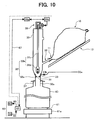
- Fig. 10 is a schematic view illustrating the cross section of another embodiment of the filling apparatus of the present invention.
- a microscopic powder toner in a first container made of a plastic film bag (10) is filled into a second container (40) through a weighing tank (30).
- the first container (10) and the weighing tank (30) are connected to each other through a hole (11) of the plastic film bag, i.e., the first container and a connector (20) of the weighing tank (30).
- the weighing tank (30) has a filling amount regulator at a discharge opening thereof to fill the second container with a predetermined amount of the toner, which opens and closes the discharge opening (31).
- the first container (10) needs to have a strength so as not to cut or break due to a weight of the toner contained therein, and a thickness (softness) so as to be easily handled (such that an opening of the bag can easily be tied or wrung).
- the first container preferably has a thickness of from 30 to 200 ⁇ m.
- the first container made of a bag is hung above the filling apparatus or is located on an inclined plate (12) formed above the apparatus.
- the first bag container (10) is easily connected to the connector with a lashing (13) such as a rubber band.
- a lashing (13) such as a rubber band.
- the connector (20) has an air discharge member (21) fluidizing the toner in the first bag container (10) and feeding the toner into the weighing tank (30) through an inside (23) of an air intake tube (22).
- a discharge amount of the toner fed in the weighing tank (30) is controlled by opening and closing a discharge opening (31) and a predetermined amount of the toner is filled in the second container (40).
- the powder filling apparatus in Fig. 10 has the following specifications:
- the uniformity of the fluidization is visually observed, and can also be observed by a light transmittance with optical means.
- the second container (40) having an internal volume of 400 cm 3 can be filled with the toner in 7 to 20 sec and a release or a sinkage of an external additive can be prevented.
- Fig. 13 is a schematic view illustrating the basic principle of the present invention, which represents a relationship among a container, a funnel and a powder as time passes and a method of filling powder of the present invention.
- a filling powder is supplied from a powder weighing tank (1) to a powder filling funnel (2) which is installed or set at a filling opening (31) of a powder container (3) (Fig. 1 (A)).
- the powder is ultra-fine particles such as a toner, it is difficult to quickly fill the powder container (3) with the powder because the particles do not easily glide on a contact slope and does not have sufficient fluidity when the particles contact to each other.
- the powder has to be quietly handled because the powder easily scatters and does not easily settle down in the air.
- the filling opening (31) of the powder container (3) and a powder discharge portion (22) of the powder filling funnel (2) are sealed such that the powder does not fly out with the air leaked therefrom. Further, the powder discharge portion (22) has to have a proper diameter so as to prevent the powder from abruptly discharging into the powder container (3).
- the powder supplied to the powder filling funnel (2) is partly filled in the powder container (3) and partly remains in the powder filling funnel (2) (Fig. 1 (B)).
- the filling speed is not high due to the air remaining in the powder container (3).
- the powder amount present in both the powder filling funnel (2) and the powder container (3) is simultaneously weighed without interrupting the filling operation.
- the powder container (3) is quickly and precisely filled with the powder by comparing total empty weight of the powder filling funnel (2) and the powder container (3) with the powder amount present therein and the total empty weight thereof (Fig. 1 (C)).
- an additional filling amount which is a shortage from a target filling amount is additionally filled at a fine-tuned refilling rate to precisely refill the target filling amount. Therefore, an additional amount filling device is separately arranged from the powder filling funnel (2), which fills a certain amount of the additional filling amount at a fine-tuned filling rate. For example, an amount which is not over or rather slightly less than the predetermined filling amount is supplied to the powder filling funnel (2), and the additional amount filling device adds a small amount of the shortage at a slow speed and fine-tuned rate while the powder remains on the powder filling funnel (2).
- the powder container (3) is preferably deaerated by force with a deaerator in order to fill the container with the powder more smoothly, which makes the bulky powder mixed with air in the powder container (3) compact to obtain a space in which the following powder can be contained.
- the funnel (2) having a release tube (23) to automatically release the air in the container can be used.
- a suction tube can be formed in the additional amount filling device.
- a microscopic powder toner in a first container (10) is filled into a powder container (3) through a powder weighing tank (1).
- the first container (10) and the weighing tank (1) are connected to each other with a connector (20) between a toner discharge opening (11) and a toner entrance of the weighing tank (10).
- the weighing tank (10) has filling amount regulator (32) filling the powder container (3) with a predetermined amount of the toner from a funnel (2) at a toner discharge opening (22) thereof while opening and closing the opening (22).
- the funnel (2) preferably has a light transmittance such that whether the powder therein is discharged into the powder container (3) can be identified from outside, and has a powder discharge portion (22) capable of fitting to a filling opening (31) of the powder container (3).
- the first container (10) has a slope inner wall (14) not to prevent the toner stored inside from falling, which smooth a discharge of the toner stored inside to the toner discharge opening (11).
- the slope inner wall (14) is a part of a hopper-shaped construction (13) at the bottom of the first container (10).
- the first container (10) and the weighing tank (1) are also connected to each other with an upper connector (50) above the connector (20), which has a slope upward from the weighing tank (1) to the first container (10) .
- the upper connector (50) keeps a pressure in the weighing tank (1) equal to that of the first container (10), and when a larger toner cloud than desired caused by some reason or other such as a too much amount of the air from the first toner fluidizer (33) is formed, the excessive air can be extracted from the weighing tank (1) into the first container (10) through the upper connector (50). Since the upper connector (50) has a slope upward, the toner accompanied with the air can be returned into the weighing tank (1).
- the toner powder discharged from the toner discharge opening (11) on the bottom of the first container (10) passes through the connector (20) into the weighing tank (1).
- the connector has an air slider formed of a perforated plate, i.e. , the second toner fluidizer (33) at least on the bottom surface, which feeds air almost all over the surface in the long direction.
- the air fed from the second toner fluidizer (33) fluidizes the toner fed through the connector (20) into the weighing tank (1) .
- the connector has a slope downward to the weighing tank (1) and helps the fluidized toner falling into the weighing tank (1) .
- the toner powder discharged from the toner discharge opening (11) is fed into the weighing tank (1) through the connector (20).
- the weighing tank (1) in this embodiment may have the filling amount regulator (32) to precisely and smoothly fill a desired amount of the toner at the toner discharge opening (22). The desired amount can optionally be fixed again.
- the filling amount regulator (32) in this embodiment is formed of a elastic ring (32a) forming the discharge opening (22) and a discharge controller (32b) controlling discharge of the toner from the discharge opening (22).
- the discharge controller (32b) is formed of a discharge control member (32d) fixed on a discharge control rod (32c) reciprocating in the weighing tank (30).
- the discharge control member (32d) is a conical member inserted into and released from the discharge opening (22) to open and close. An opening and closing degree of the discharge opening (22) depends on an inserting degree of the conical discharge control member (32d) fixed on the discharge control rod (32c) reciprocating in the weighing tank (1) into the discharge opening (22) formed by the elastic ring (32a).
- the discharge opening (22) is half opened according to the insert level, i.e., the toner is partly discharged.
- a flexible covering member (37) is located on a sleeve (30a) of the discharge opening (22), and this covering member (37) can be spared.
- such an elastic ring (32a) does not cause toner filming over a surface thereof and of the discharge control member (32d) even when contacting thereto. It is thought that a stress is scarcely given to the toner inevitably remained between the elastic ring (32a) and the discharge control member (32d) even when they are contacted to each other.
- the filling amount regulator at the discharge opening (22) in the weighing tank (1) is not limited to this embodiment.
- the discharge opening (22) can be properly formed of an elastic material and a plate member can be used as an openness regulation member, which is adjacent to the discharge opening (22) and slides ahead and backward in plane direction.
- a relative location between the discharge opening (22) and a movable member having an opening conformed to the opening thereof can control the openness.
- An air pressure cylinder, a motor, a hydraulic cylinder, etc. can be used as the drive unit (39), and the air pressure cylinder is used in this embodiment.
- a source piping for a compressed air used for the first toner fluidizer (33) can distribute the compressed air to the driving source (39b) to drive the drive unit (39).
- the first toner fluidizer (33) in this embodiment has many pores discharging air and a first air lead-in tube (33a) leading the compressed air into a porous material therein.
- a porous sinter having a smooth surface is used.
- this embodiment of the powder filling apparatus has a discharger (not shown) to eliminate static electricity in order to prevent a toner dust explosion.
- the first toner fluidizer (33) is formed in a whole circumference close to the discharge opening (22) in the weighing tank (1) in order to obtain a desired toner dischargeability, which is different from the partially formed thin-stripe toner fluidizer (33) in the first container (10).
- a moving amount of the toner powder has a range in proportion to a feeding amount of air, and the moving amount of the toner can be fixed more or less by controlling the feeding amount of air.
- an area size of each toner fluidizer (33) i.e., the number of holes of each toner fluidizer largely depends on the available amount of air.
- the weighing tank (1) having a smaller cross section toward the discharge opening (22) can circumferentially have several continuous stages of air feeding opening or have such a feeding structure as can feed air in spiral direction.
- the first air lead-in tube (33a) has a first air feeding control valve (33b) stopping feeding air, starting feeding air and controlling an amount of the feeding air.
- a first air feeding control valve (33b) stopping feeding air, starting feeding air and controlling an amount of the feeding air.
- at least one of the air lead-in tubes (33a) preferably has such an air feeding control valve.
- the weighing tank (1) of the filling apparatus of the present invention can have pressure controller increasing and decreasing an inside pressure.
- the first container can have such pressure controller instead of the weighing tank or together therewith.
- Such pressure controller control an inside pressure or a toner cloud in the first container (10) and/or the weighing tank (1) into which air is fed from the above-mentioned first to third toner fluidizer.
- the filling apparatus of the present invention can insert a suction tube (23) into the powder container (3) in order to extract air therein filled with the toner.
- the powder discharge portion of the funnel (2) is a hollow tube and the release tube (23) is inserted into the powder container (3) therefrom.
- the release tube (23) is unified with the funnel (2) such that the tube is released from and inserted into the opening (31) of the powder container (3) to release the air therein from a tip of the tube.
- the inserted tip of the release tube (23) has a mesh material only the air passes through and the toner particles do not.
- the powder filling apparatus of the present invention preferably has a filled toner weigher weighing the filled powder toner in the powder container (3), and the filled toner weigher (41) in this embodiment has a load cell (61) weighing the filled toner weight in the powder container (3) thereon.
- the load cell (61) is located on a lifter (61a) timely changing a distance between the weighing tank (1) and the powder container (3) while lifting and descending the load cell.
- the load cell (61) has monitor (63) displaying a weight of the filled powder toner.
- a monitor known displays such as pressure detector detecting a voltage changed according to an elastic deformation degree due to a weight or a pressure or a pressure detection device such as a piezoelectric device directly changing an electromotive force according to a pressure can be used. Filling or stopping filling the toner can be made while seeing a filled amount (weight) of the toner displayed on the monitor (63).
- the filled toner weigher (60) optionally has a processor (62) computing the filled toner weight from a difference between an empty total weight of the powder container (3), filling funnel (2) and suction tube (23) and a gross weight thereof filled with the toner.
- the processor (62) has input device (64) which can input a predetermined filling weight of the toner and change the predetermined filling weight thereof while seeing the weight displayed on the monitor (63).
- the processor (62) sends a drive instruction signal to the driving control apparatus (39a) controlling the driving source (39b) of the driving apparatus (39) based on a result of the computation, and the driving control apparatus (39a) reciprocates the discharge control rod (32c) based on the instruction.
- various CPUs from a simple analogue voltage comparator to a microcomputer chip can be used.
- an AD converter converting an analogue signal into a digital signal, e.g. , a pulse signal according to a difference of a predetermined potential is attached as a matter of course.
- the discharge opening (31) is fully opened.
- a root of the conical discharge control member (32d) having a large diameter descends until the root is completely inserted into the discharge opening (31)
- the discharge opening (31) is completely closed.
- the conical discharge control member (32d) is not completely released from the discharge opening (31) and not completely inserted thereinto, i.e., when the member is inserted thereinto such that there is a clearance between the member and the opening, the discharge opening (31) is half opened according to the insert level. Therefore, it can be adjusted so as to have any levels.
- the discharge control rod (32c) of the embodiment of the powder filling apparatus shown in Fig. 15 has three reciprocation degrees, i.e., a completely closed degree, a fully opened degree and a half opened degree which is in the middle therebetween since controlling an amount of feeding air to the first to third air lead-in tubes (33a) also can control filling.
- the input device (64) in this embodiment is a button-cum-dial digital switch as a (binary) code generator.
- the processor (62) is a CPU with a keyboard, as a matter of course, a RAM rewritably storing various data including a weight based on a result of the computation and /or an input signal from the input device, i.e., calling the data in the CPU, computing and storing again a result of the computation and a ROM storing various programs including a processing program for processing the data and various instructing programs so as to be called in at anytime can be installed in the processor (62).
- the processor (62) can be configured, e.g., so as to have a program sending a opening and closing instruction to each of the air feeding control valves (33b).
- the apparatus of the present invention can be transportable when formed on a carrier (90) with a castor (91).
Landscapes
- Engineering & Computer Science (AREA)
- Mechanical Engineering (AREA)
- Quality & Reliability (AREA)
- Basic Packing Technique (AREA)
Abstract
Description
- The present invention relates to an apparatus and a method of filling a desired amount of a microscopic toner powder for developing an electrostatic latent image into a second container without excess or deficiency from a first container.
- Conventionally, a powder toner for developing an electrostatic latent image is often filled from a first container into other second containers. For example, Japanese Laid-Open Patent Publication No. 9-193902 discloses a method of filling a toner powder into a toner receiving container from a toner feeding container equipped with an auger inside for stirring the toner and a rotary valve at the bottom. The method includes a process of increasing fluidity of the toner by feeding air into the toner stirred in the toner feeding container and a process of feeding the toner into the toner receiving container through a feeding tube and compressing the toner to fill the toner therein in the high density, wherein an exhaust tube for circulation located between the toner feeding container and the feeding tube separates the air from the toner and circulates the air including the toner into the toner feeding container.
- A toner for developing an electrostatic latent image is a powder having an extremely small particle diameter and has less fluidity than the other powders such as ceramic materials in spite of having less specific gravity than the other powders, and what is worse, has high agglutinability. Recently in particular, smaller particle diameter is required to comply with demands for a high-resolution image and a lower-temperature melting resin is required to comply with demands for saving energy and an instant high-speed fixation, resulting in problems of agglomeration, adherence to and filming of the toner over a surface of the other materials. Accordingly, in order to improve these properties and avoid the fluidity deterioration and agglomeration, in many cases, ultra-fine particles such as a fluidity improver, an agglomeration inhibitor and a charge controlling agent to improve chargeability of the toner are applied to a surface thereof. Therefore, in terms of preventing these ultra-fine particles from separating and releasing from the toner and maintaining the chargeability, fluidity and agglomeration resistance thereof, it is not desirable that the toner is stirred or fed by means of an auger or a screw conveyor giving an excessive stress thereto.
- Particularly, a color toner has a small particle diameter, and includes a charge controlling agent, a fluidizer, an agglomeration inhibitor and a fusion inhibitor on a surface thereof. Therefore, the color toner has poor fluidity because the particles intertangle each other, and it is not desirable to use a conventional mechanical apparatus such as a rotary valve and an auger since a strong external force applied to the toner involves the risk of impairing the properties thereof.
- When a toner and air are mixed to make the toner pneumatic, a toner cloud (a nebula toner formed from a mixture of a toner and air) having a floating ultra-microscopic toner is formed and a volume of the toner bloats. It is difficult to quickly separate air from the toner cloud only by a structure and a location of a separation tube, and therefore it is difficult to control a compressed amount of the toner by an air separation from the toner cloud using such a piping. When air is supplied to the extremely microscopic toner, a flowing phase thereof expands quickly and easily changes to a dust phase, and it takes time to collect the toner from the dust phase and the dust contaminates the circumference. Once a toner cloud is formed, it takes from several to several decade hours for the toner to fall onto the bottom by itself. It is not easy to fluidize the accumulated toner and fill it into a second container while moderately feeding air to prevent formation of a large toner cloud.
- In addition, when the toner is distributed from a first storage container into many second containers, the toner in the second containers occasionally has an irregular ingredient due to the air fed into the storage container.
- Because of these reasons, a need exists for an apparatus and a method of fluidizing a toner stored in a first container, and quickly and precisely distributing the toner into a small container without impairing the toner properties and composition and contaminating the circumference, which is easily automated and has good tractability.
- Accordingly, an object of the present invention is to provide an apparatus and a method of quickly filling a desired amount of a toner into a second container without giving a particular stress thereto, contaminating the environment or exposing an operator to danger.
- Another object of the present invention is to provide a technology which can be used for a toner feeder on a production line thereof as well as a distribution of the toner from a temporary storage container, and which can be used by an end-user to fill the toner into a second container on-demand in an extreme case.
- Briefly these objects and other objects of the present invention as hereinafter will become more readily apparent can be attained by a powder filling apparatus including a first container configured to contain a powder; a weighing tank configured to receive the powder from the first container and discharge a predetermined amount of the powder to a second container, which includes an opening configured to discharge the powder into the second container and a regulator configured to open and close the opening to discharge a predetermined amount of the powder into the second container; and a connector configured to feed the powder from the first container into the weighing tank.
- In addition, the regulator of the powder filling apparatus can preferably perform at least three levels of discharging including freely discharging, stopping discharging and partially discharging the powder.
- Further, the weighing tank of the powder filling apparatus includes a powder fluidizer to fluidize the powder fed from the weighing tank to the second container through the opening.
- These and other objects, features and advantages of the present invention will become apparent upon consideration of the following description of the preferred embodiments of the present invention taken in conjunction with the accompanying drawings.
- Various other objects, features and attendant advantages of the present invention will be more fully appreciated as the same becomes better understood from the detailed description when considered in connection with the accompanying drawings in which like reference characters designate like corresponding parts throughout and wherein:
- Fig. 1 is a schematic view illustrating the cross section of an embodiment of the filling apparatus of the present invention;
- Fig. 2 is a schematic view illustrating the cross section of the first container in Fig. 1;
- Fig. 3 is a schematic view illustrating the cross section of another embodiment of the filling apparatus of the present invention;
- Fig. 4 is a schematic view illustrating the cross section of another embodiment of the filling apparatus of the present invention;
- Fig. 5 is a schematic view illustrating the cross section of another embodiment of the filling apparatus of the present invention;
- Fig. 6 is a schematic view illustrating the cross section of another embodiment of the filling apparatus of the present invention;
- Fig. 7 is a schematic view illustrating the cross section of another embodiment of the filling apparatus of the present invention;
- Fig. 8 is a schematic view illustrating another embodiment of the filling apparatus of the present invention;
- Fig. 9 is a schematic view illustrating an embodiment of the discharge regulation member of the present invention;
- Fig. 10 is a schematic view illustrating the cross section of another embodiment of the filling apparatus of the present invention;
- Fig. 11 is a schematic view illustrating the cross section of a connected part of a large bag container and a connector in Fig. 10;
- Fig. 12 is a schematic view illustrating the cross section of an embodiment of the connector of the present invention;
- Fig. 13 is a schematic view illustrating the basic principle of the present invention, which represents a relationship among a container, a funnel and a powder as time passes and a method of filling powder of the present invention;
- Fig. 14 is a schematic view illustrating an embodiment of the funnel installed in the filling apparatus of the present invention;
- Fig. 15 is a schematic view illustrating an embodiment of the filling apparatus of the present invention; and
- Fig. 16 is a schematic view illustrating another embodiment of the filling apparatus of the present invention.
-
- Generally, the present invention provides an apparatus and a method which can solve problems when a second container is directly filled with a toner from a first container containing or storing the microscopic toner powder. It is difficult to constantly discharge a certain amount of the toner from the first container without giving a stress to the toner because the microscopic toner powder has a peculiar fluidity. In addition, it is difficult to precisely fill the second container with a desired amount of the toner by strongly and weakly discharging the toner, temporarily stopping discharging or discharging in drops. Further, it is necessary to change the discharge amount of the toner, e.g., when the discharge amount comes close to a predetermined filling amount of the second container, the discharge amount is often controlled while seeing whether the amount reaches the predetermined amount or estimating when the amount reaches the predetermined amount. The filling method of the present invention can quickly, easily and precisely fill a container.
- In the present invention, a toner is discharged into a weighing tank from a first container and a desired amount of the toner is filled in a second container by the weighing tank. However, as mentioned later, the weighing tank does not necessarily fill the second container with the toner after the toner is discharged into the weighing tank from the first container. The weighing tank can fill the second container with the toner almost simultaneously when the toner is discharged into the weighing tank from the first container in the present invention.
- In the present invention, the discharge from the first container into the weighing tank is suitable for a quick discharge of a large amount of the toner and the filling from the weighing tank into the second container is suitable for filling a precise desired amount of the toner, and accordingly a combination of which improves the filling operation. It can be considered that the toner is discharged from a first container into a second weighing container having a capacity of a filing amount unit. Although this is possible in the present invention, only a desired amount of the toner can be filled by filling amount regulator in the present invention. Although the first container and the weighing tank of the present invention do not always work in a good timing, which is not necessarily indispensable, the filling amount regulator having a precise structure and performance in the weighing tank smoothly and precisely filling the second container with a desired amount of the toner can not only have the first container and the weighing tank work in a good timing but also quickly fill the second container with the toner. Further, when first toner fluidizer and the filling amount regulator in the weighing tank work together, the toner can more quickly and precisely be filled. In addition, controlling a feeding amount of air from the first toner fluidizer can control the filling amount of the toner into the second container to some extent. Thus, the toner can smoothly be filled without a mechanical stress thereto.
- In the present invention, the first container preferably has a slope bottom surface and a third toner fluidizer feeding air thereon to slightly inflate or float a powder toner filled in the container, promote falling of the toner to a toner discharge opening on the bottom and smooth a discharge of the toner therefrom without a mechanical stress to the toner. In addition, by controlling a feeding amount of the air from the third toner fluidizer, a discharge amount of the toner from the first container into the weighing tank can be controlled or the discharge of the toner can be stopped. Such a construction prevents the toner from accumulating or agglutinating on an inside surface of the container to prevent an intermittent discharge of the toner, and prevents the toner from densely accumulating on the toner discharge opening on the bottom to smooth the discharge of the toner into the weighing tank.
- The first container and the weighing tank are not necessarily unified and the toner discharged from the first container is preferably fed into the weighing tank through a connector which is a contact route between the first container and the weighing tank. The connector preferably has second toner fluidizer and controlling a feeding amount of air therefrom can prevent the toner particles from crosslinking in the connector to control a discharge amount of the toner therethrough into the weighing tank or stopping feeding air can stop discharging the toner. In addition, a pressure controller controlling an inside air pressure can optionally be arranged either in the first container or the weighing tank in the present invention.
- In addition, in order to aspirate air in the second container to prevent a toner cloud (a nebula toner formed from a mixture of a toner and air) having a floating toner therein, a suction tube can be inserted into the second container to aspirate only the air without passing the filled toner particles therethrough in the present invention.
- The present invention preferably has a filled toner weight controller controlling a filled amount of the powder toner into the second container, which can be, e.g., a conventional load cell weighing an article loaded thereon and having a monitor displaying a weight of the article.
- In addition, the present invention can optionally be constituted such that the filled toner weight controller can smoothly work based on the toner weight weighed by the load cell and the feeding amount of air from the first or third toner fluidizer. Further, a control signal for that purpose can be sent from a central processing apparatus and a timing to send the signal can be computed. The central processing apparatus can have input device giving an instruction or a change instruction thereto to previously fix a required filling amount or change the filling amount.
- Hereinafter, the present invention will be specifically explained based on the drawings.
- Fig. 1 is a schematic view illustrating the cross section of an embodiment of the filling apparatus of the present invention.
- In the filling apparatus of Fig. 1, a microscopic powder toner in a first container (10) is filled into a second container (40) through a weighing tank (30). The first container (10) and the weighing tank (30) are connected to each other with a connector (20) between a toner discharge opening (11) and a toner entrance of the weighing tank (30). The weighing tank (30) has filling amount regulator (32) filling the second container (40) with a predetermined amount of the toner at a toner discharge opening (31) thereof while opening and closing the opening (31).
- The first container (10) has a slope inner wall (12) not to prevent the toner stored inside from falling, which smooth a discharge of the toner stored inside to the toner discharge opening (11). In this embodiment, the slope inner wall (12) is a part of a hopper-shaped construction (13) of the first container (10).
- As shown in Fig. 2, the hopper-shaped construction (13) of the first container (10) is constituted of a vertical base plate (13a), rough triangle side plates (13b) and (13c) inclined inside on both sides of the vertical base plate (13a) and rough triangle back plates (13d) and (13e) inclined inside facing the vertical base plate (13a). The hopper-shaped construction (13) has a cross section of an inverted trapezoid and a shape of a square-built teepee type having a downslope. A joined valley portion (14) between the back plates (13d) and (13e) has third toner fluidizer (15) fluidizing the toner to promote falling of the microscopic powder toner. A third air lead-in tube (15a) for the third toner fluidizer (15) has 3 branches on the bottom and both walls of the valley portion (14), and each branch has air feeding control valve (15b).
- First toner fluidizer (33) located in the weighing tank (30) as well as second toner fluidizer located in the connector (20) can prevent an interruption of the toner feeding or falling of the toner in drops. In addition, controlling an amount of feeding air can control a feeding amount of the toner and a size of a toner cloud (a nebula toner formed from a mixture of a toner and air) having a floating ultra-microscopic toner.
- The first container (10) and the weighing tank (30) are also connected to each other with an upper connector (50) above the connector (20), which has a slope upward from the weighing tank (30) to the first container (10). The upper connector (50) keeps a pressure in the weighing tank (30) equal to that of the first container (10), and when a larger toner cloud than desired caused by some reason or other such as a too much amount of the air from the first toner fluidizer (33) is formed, the excessive air can be extracted from the weighing tank (30) into the first container (10) through the upper connector (50). Since the upper connector (50) has a slope upward, the toner accompanied with the air can be returned into the weighing tank (30).
- The toner powder discharged from the toner discharge opening (11) on the bottom of the first container (10) passes through the connector (20) into the weighing tank (30). The connector has an air slider formed of a perforated plate, i.e. , the second toner fluidizer (21) at least on the bottom surface, which feeds air almost all over the surface in the long direction. The air fed from the second toner fluidizer (21) fluidizes the toner fed through the connector (20) into the weighing tank (30). The connector has a slope downward to the weighing tank (30) and helps the fluidized toner falling into the weighing tank (30).
- The toner powder discharged from the toner discharge opening (11) is fed into the weighing tank (30) through the connector (20). The weighing tank (30) in this embodiment has the filling amount regulator (32) at the toner discharge opening (31) to precisely and smoothly fill a desired amount of the toner. The desired amount of the toner can optionally be fixed again.
- The filling amount regulator (32) in this embodiment is formed of a elastic ring (32a) forming the discharge opening (31) and a discharge controller (32b) controlling discharge of the toner from the discharge opening (31). The discharge controller (32b) is formed of a discharge control member (32d) fixed on a discharge control rod (32c) reciprocating in the weighing tank (30). The discharge control member (32d) is a conical member inserted into and released from the discharge opening (31) to open and close the discharge opening (31). An opening and closing degree of the discharge opening (31) depends on an inserting degree of the conical discharge control member (32d) fixed on the discharge control rod (32c) reciprocating in the weighing tank (30) into the discharge opening (31) formed by the elastic ring (32a).
- When a conical tip having a small diameter of the discharge control member (32d) ascends until the tip is completely released from the discharge opening (31), the discharge opening (31) is fully opened, i.e., the toner is freely discharged. When a root of the conical discharge control member (32d) having a large diameter descends until the root is completely inserted into the discharge opening (31), the discharge opening (31) is completely closed, i.e., the toner discharge stops. When the conical discharge control member (32d) is not completely released from the discharge opening (31) and not completely inserted thereinto, i.e., when the member is inserted thereinto such that there is a clearance between the member and the opening, the discharge opening (31) is half opened according to the insert level, i.e. , the toner is partly discharged. A flexible covering member (37) is located on a sleeve (30a) of the discharge opening (31), and this covering member (37) can be spared.
- As shown in Fig. 1, the closer to the discharge opening (31), the thinner the thickness of the elastic ring (32a) having a wedge-shaped cross section. Therefore, the thinner part thereof has more flexibility, which contacts the discharge control member (32d) when completely inserted thereinto. In the present invention, such an elastic ring (32a) does not cause toner filming over a surface of the elastic ring (32a) and the discharge control member (32d) even when contacting thereto. It is thought that a stress is scarcely given to the toner inevitably remained between the elastic ring (32a) and the discharge control member (32d) even when they are contacted to each other.
- However, in the present invention, the filling amount regulator at the discharge opening (31) in the weighing tank (30) is not limited to this embodiment. For example, the discharge opening (31) can be properly formed of an elastic material and a plate member can be used as an openness regulation member, which is adjacent to the discharge opening (31) and slides ahead and backward in plane direction. In addition, a relative location between the discharge opening (31) and a movable member having an opening conformed to the opening of the discharge opening (31) can control the openness.
- A drive unit (39) driven by a driving source (39b) controlled by a driving control apparatus (39a) reciprocates the discharge rod (32c). An air pressure cylinder, a motor, a hydraulic cylinder, etc. can be used as the drive unit (39), and the air pressure cylinder is used in this embodiment. A source piping for a compressed air used for the first toner fluidizer (33), the second toner fluidizer (21) and the third toner fluidizer (15) can distribute the compressed air to the driving source (39b) to drive the drive unit (39).
- The first toner fluidizer (33) in this embodiment has many pores discharging air and a first air lead-in tube (33a) leading the compressed air into a porous material therein. Similarly, the second toner fluidizer (21) has many pores discharging air and a second air lead-in tube (21a) leading the compressed air into a porous material therein, and the third toner fluidizer (15) has many pores discharging air and a third air lead-in tube (15a) leading the compressed air into a porous material therein. In this embodiment, a porous sinter having a smooth surface is used. In addition, this embodiment of the powder filling apparatus has a discharger (not shown) to eliminate static electricity in order to prevent a toner dust explosion.
- As shown in Fig. 1, the first toner fluidizer (33) is formed in a whole circumference close to the discharge opening (31) in the weighing tank (30) in order to obtain a desired toner dischargeability, which is different from the third toner fluidizer (15) in the first container (10). A moving amount of the toner powder has a range in proportion to a feeding amount of air, and the moving amount of the toner can be fixed more or less by controlling the feeding amount of air. However, when a similar air discharging material is used, an area size of each toner fluidizer (33), (21) and (15), i.e., the number of holes of each toner fluidizer largely depends on the available amount of air. Particularly, the weighing tank (30) having a smaller cross section toward the discharge opening (31) can circumferentially have several continuous stages of air feeding opening or have such a feeding structure as can feed air in spiral direction.
- The first air lead-in tube (33a) has a first air feeding control valve (33b) stopping feeding air, starting feeding air and controlling an amount of the feeding air. Similarly, the second air lead-in tube (21a) has a second air feeding control valve (21b) stopping feeding air, starting feeding air and controlling an amount of the feeding air, and the third air lead-in tube (15a) has a third air feeding control valve (15b) stopping feeding air, starting feeding air and controlling an amount of the feeding air. However, in the present invention, at least one of the air lead-in tubes (33a), (21a) and (15a) preferably has such an air feeding control valve.
- In addition, as shown in Fig. 5, the weighing tank (30) of the filling apparatus of the present invention can have a pressure controller (36) increasing and decreasing an inside pressure. The first container can have such pressure controller instead of the weighing tank or together therewith. Such pressure controller control an inside pressure or a toner cloud in the first container (10) and/or the weighing tank (30) into which air is fed from the above-mentioned first to third toner fluidizer.
- Further, the filling apparatus of the present invention can insert a suction tube into the second container in order to extract air therein filled with the toner.
- Namely, as shown in Fig. 3, the hollow discharge control rod (32c) inserts a suction tube (38) into the second container (40) from the hollow portion and extracts air therein from the tip of the tube. The insert opening tip of the suction tube (38) has a mesh (38a) not passing the toner particles and passing only air. Such a double structure can prevent a vibration of the suction tube (38) or a noise due to the vibration. Further, in order to prevent a resonance between the hollow discharge control rod (32c) and the suction tube (38) inserted therein, a resonance inhibitor can be filled at a desired part of a clearance therebetween, which can also be used as a fixer fixing the double structure formed of the hollow discharge control rod (32c) and the suction tube (38) inserted therein.
- In addition, as shown in Fig. 4, as a matter of course, the suction tube (38) can be inserted into the second container (40) from a location which is different from the discharge control rod (32c) and extract the air in the second container from the tip. The toner filing apparatus having such a separated structure of the present invention can flexibly be produced without a need of strict preciseness of the size.
- In addition, the powder filling apparatus of the present invention preferably has a filled toner weigher weighing the filled powder toner in the second container (40), and the filled toner weigher (60) in this embodiment has a load cell (61) weighing the filled toner weight in the second container (40) thereon. The load cell (61) is located on a lifter (61a) timely changing a distance between the weighing tank (30) and the second container (40) while lifting and descending the load cell. The load cell (61) has a monitor (63) displaying a weight of the filled powder toner.
- As such a monitor, known displays such as pressure detectors detecting a voltage changed according to an elastic deformation degree due to a weight or a pressure, or a pressure detection device such as a piezoelectric device directly changing an electromotive force according to a pressure can be used. Filling or stopping filling the toner can be made while seeing a filled amount (weight) of the toner displayed on the monitor (63).
- The filled toner weigher (60) optionally has a processor (62) computing the filled toner weight from a difference between an empty weight of the second container (40) and a gross weight thereof filled with the toner.
- The processor (62) has an input device (64) which can input a predetermined filling weight of the toner and change the predetermined filling weight thereof while seeing the weight displayed on the monitor (63). In addition, the processor (62) sends a drive instruction signal to the driving control apparatus (39a) controlling the driving source (39b) of the driving apparatus (39) based on a result of the computation, and the driving control apparatus (39a) reciprocates the discharge control rod (32c) based on the instruction. As the processor (62), various CPUs from a simple analogue voltage comparator to a microcomputer chip can be used. When the analogue voltage comparator is used, an AD converter converting an analogue signal into a digital signal, e.g., a pulse signal according to a difference of a predetermined potential is associated, as a matter of course.
- As mentioned above, when a conical tip having a small diameter of the discharge control member (32d) of the discharge control rod (32c) ascends until the tip is completely released from the discharge opening (31), the discharge opening (31) is fully opened. When a root of the conical discharge control member (32d) having a large diameter descends until the root is completely inserted into the discharge opening (31), the discharge opening (31) is completely closed. When the conical discharge control member (32d) is not completely released from the discharge opening (31) and not completely inserted thereinto, i. e. , when the member is inserted thereinto such that there is a clearance between the member and the opening, the discharge opening (31) is half opened according to the insert level. Therefore, it can be adjusted so as to have any levels. However, the discharge control rod (32c) of the embodiment of the powder filling apparatus shown in Fig. 1 has three reciprocation degrees, i.e., a completely closed degree, a fully opened degree and a half opened degree which is in the middle therebetween since controlling an amount of feeding air to the first to third air lead-in tubes (33a), (21a) and (15a) also can control filling the powder.
- The input device (64) in this embodiment is a button-cum-dial digital switch as a (binary) code generator. When the processor (62) is a CPU with a keyboard, as a matter of course, a RAM rewritably storing various data including a weight based on a result of the computation and /or an input signal from the input device, i.e., calling the data in the CPU, computing and storing again a result of the computation and a ROM storing various programs including a processing program for processing the data and various instructing programs so as to be called in at anytime can be installed in the processor (62). Then, the processor (62) can be configured, e.g., so as to have a program sending a opening and closing instruction to the first to third air feeding control valves (33b), (21b) and (15b).
- In addition, as shown in Fig. 6, the powder filling apparatus of the present invention can have plural connectors connecting the first container (10) with the weighing tank (30), the openings of which feed a microscopic powder into a filling cylinder from different locations of the first container respectively. Further, one of the connectors can be a pressure control member keeping a pressure of an upper space of the weighing tank (30) not greater than an ambient pressure.
- As shown in Fig. 7, the elastic ring (32a) in the powder filling apparatus of the present invention has a steep slope at the upper part and a gentle slope at the bottom, and a thinner thickness from the periphery toward the discharge opening (31) to prevent the toner adherence to a surface thereof. Suction means (34) instead of the above-mentioned suction tube (38) can be located at a periphery of the sleeve (30a), which does not have the discharge opening (31) of the elastic ring (32a). In addition, a distributor for feeding air (35) uniformly distributing air to the first toner fluidizer (33) can also be located.
- In the filling apparatus of the present invention, when an accumulated amount of the toner at the discharge opening of the first container increases and passing speed of the toner powder in the connector decreases due to an increased air resistance, the toner feed automatically stops in some cases. Although fluidizing the toner prevents this, an inflation degree of the toner layer (largeness of the toner cloud) by feeding air into the first container is preferably from 20 to 500 % of a depth of the toner layer. When less than 20 %, the toner is not smoothly discharged. When greater than 500 %, an local excessive feeding or a blow up of the toner powder occurs in the container. An inflation degree of the toner layer (largeness of the toner cloud) in the weighing tank is preferably from 25 to 600 % of a depth of the toner layer. In addition, as means of increasing a powder density of the fluidized toner layer, the powder can be fed in a divided pulsed form by intermittently feeding air from a divided porous air slider.
- The powder filling apparatus in Fig. 1 can be used in a toner manufacturing, storage and shipping facility or near a copier in an office. When the apparatus is used near a copier, the apparatus is preferably located with a pressure vessel as an air supply source on a carriage, and in addition, a compressor storing compressed air in the pressure vessel can be attached thereto.
- A shape and material of the first container (10) are shown in Fig. 8. The first container (10) has a capacity of from 25 to 500 1, and typically has a toner containing capacity of from 10 to 200 kg. The first container (10) preferably has a bottom having a gradient angle of from 30 to 60°, and the connector (20) is preferably fixed to the first container at a gradient angle of from 30 to 60°.
- The weighing tank (30) has a capacity of from 0.5 to 20 1, and it is preferable that the tank typically has a toner containing capacity of from 50 to 2,000 g. A two-component non-magnetic (color or monochrome) toner, a one-component non-magnetic (color or monochrome) toner, a one-component magnetic (monochrome) toner, a ferrite carrier developer and a magnetite carrier developer can be used in the apparatus.
- The apparatus starts fluidizing the toner at an air pressure from 3 to 5 kg/cm2 and an air feeding amount of 0.1 to 11/min, and the fluidization typically becomes stable in 5 to 20 sec.
- As previously mentioned, feeding air into the weighing tank (30) further stabilizes (fixes) an air content (a ratio between a solid content and air).
- The discharge control member (32d) of the apparatus preferably has an outer diameter of from 5 to 50 mm, and the elastic ring (32a) preferably has an inner diameter of from 5 to 50 mm. A difference between the outer diameter of the discharge control member and the inner diameter of the elastic ring (32a) is typically from -0.5 to +2.0 mm.
- A shape and material of the discharge control member (32d) are specifically shown in detail in Fig. 9. When the discharge control member (32d) is lifted, a clearance between the elastic ring (32a) and the discharge control member (32d) expands and the toner starts falling to fill the small container (40).
- The discharge opening (31) is opened or closed by inserting or releasing the discharge control member (32d) into or from the elastic ring (32a) . Typically, in the first stage, when an insertion level of the discharge control member (32d) into the elastic ring (32a) is from 0 to 10 %, an openness of the discharge opening (31) is from 95 to 100 %. In the second stage, when the insertion level is 40 to 60 %, the openness is 5 to 30 %. In the third stage, when the insertion level is 95 to 100 %, the openness is 0 to 5 %.
- In the first stage, almost all of a specified amount of the toner is filled in the small container (40). In the second stage, the toner is precisely filled therein until the container is filled with the specified amount of the toner. In the third stage, when the container is filled with the specified amount of the toner, toner feeding is stopped.
- Fig. 10 is a schematic view illustrating the cross section of another embodiment of the filling apparatus of the present invention. In Fig. 10, a microscopic powder toner in a first container made of a plastic film bag (10) is filled into a second container (40) through a weighing tank (30). The first container (10) and the weighing tank (30) are connected to each other through a hole (11) of the plastic film bag, i.e., the first container and a connector (20) of the weighing tank (30). The weighing tank (30) has a filling amount regulator at a discharge opening thereof to fill the second container with a predetermined amount of the toner, which opens and closes the discharge opening (31).
- The first container (10) needs to have a strength so as not to cut or break due to a weight of the toner contained therein, and a thickness (softness) so as to be easily handled (such that an opening of the bag can easily be tied or wrung). For example, the first container preferably has a thickness of from 30 to 200 µm. The first container made of a bag is hung above the filling apparatus or is located on an inclined plate (12) formed above the apparatus.
- As Fig. 11 shows, the first bag container (10) is easily connected to the connector with a lashing (13) such as a rubber band. When an end of the connector almost agrees to a location of the hole of the bag, the residual toner in the first bag container (10) can be minimized in filling the second container (40) with the toner.
- As Fig. 12 shows, the connector (20) has an air discharge member (21) fluidizing the toner in the first bag container (10) and feeding the toner into the weighing tank (30) through an inside (23) of an air intake tube (22).
- A discharge amount of the toner fed in the weighing tank (30) is controlled by opening and closing a discharge opening (31) and a predetermined amount of the toner is filled in the second container (40).
- The powder filling apparatus in Fig. 10 has the following specifications:
- a capacity of the first container (10): 40 to 50 1
- a toner amount: 10 to 15 kg
- a filling method: fluidizing the toner and the toner falls by gravitation
- the toner: a two-component non-magnetic color toner, a one-component non-magnetic color toner, a one-component non-magnetic black toner and a one-component magnetic black toner
- fluidizing time: 5 to 15 min
- a shape of the first container (10) : a flat bag or a tapered bag
- fluidizer: a porous resin material having a
hole diameter 2 to 15 µm, a porosity of 30 % and a thickness 5m - feeding amount of air: 1 to 5 1/min.
-
- The uniformity of the fluidization is visually observed, and can also be observed by a light transmittance with optical means. The second container (40) having an internal volume of 400 cm3 can be filled with the toner in 7 to 20 sec and a release or a sinkage of an external additive can be prevented.
- Fig. 13 is a schematic view illustrating the basic principle of the present invention, which represents a relationship among a container, a funnel and a powder as time passes and a method of filling powder of the present invention. In Fig. 13, a filling powder is supplied from a powder weighing tank (1) to a powder filling funnel (2) which is installed or set at a filling opening (31) of a powder container (3) (Fig. 1 (A)). When the powder is ultra-fine particles such as a toner, it is difficult to quickly fill the powder container (3) with the powder because the particles do not easily glide on a contact slope and does not have sufficient fluidity when the particles contact to each other. In addition, the powder has to be quietly handled because the powder easily scatters and does not easily settle down in the air. Therefore, the filling opening (31) of the powder container (3) and a powder discharge portion (22) of the powder filling funnel (2) are sealed such that the powder does not fly out with the air leaked therefrom. Further, the powder discharge portion (22) has to have a proper diameter so as to prevent the powder from abruptly discharging into the powder container (3).
- The powder supplied to the powder filling funnel (2) is partly filled in the powder container (3) and partly remains in the powder filling funnel (2) (Fig. 1 (B)). The filling speed is not high due to the air remaining in the powder container (3).
- In the present invention, the powder amount present in both the powder filling funnel (2) and the powder container (3) is simultaneously weighed without interrupting the filling operation. The powder container (3) is quickly and precisely filled with the powder by comparing total empty weight of the powder filling funnel (2) and the powder container (3) with the powder amount present therein and the total empty weight thereof (Fig. 1 (C)).
- In addition, based on the recognized filling powder amount, an additional filling amount which is a shortage from a target filling amount is additionally filled at a fine-tuned refilling rate to precisely refill the target filling amount. Therefore, an additional amount filling device is separately arranged from the powder filling funnel (2), which fills a certain amount of the additional filling amount at a fine-tuned filling rate. For example, an amount which is not over or rather slightly less than the predetermined filling amount is supplied to the powder filling funnel (2), and the additional amount filling device adds a small amount of the shortage at a slow speed and fine-tuned rate while the powder remains on the powder filling funnel (2).
- In addition, the powder container (3) is preferably deaerated by force with a deaerator in order to fill the container with the powder more smoothly, which makes the bulky powder mixed with air in the powder container (3) compact to obtain a space in which the following powder can be contained.
- For example, as means of forcible deaeration, as Fig. 14 shows, the funnel (2) having a release tube (23) to automatically release the air in the container can be used. In addition, a suction tube can be formed in the additional amount filling device.
- In the filling apparatus of Fig. 15, a microscopic powder toner in a first container (10) is filled into a powder container (3) through a powder weighing tank (1). The first container (10) and the weighing tank (1) are connected to each other with a connector (20) between a toner discharge opening (11) and a toner entrance of the weighing tank (10). The weighing tank (10) has filling amount regulator (32) filling the powder container (3) with a predetermined amount of the toner from a funnel (2) at a toner discharge opening (22) thereof while opening and closing the opening (22).
- The funnel (2) preferably has a light transmittance such that whether the powder therein is discharged into the powder container (3) can be identified from outside, and has a powder discharge portion (22) capable of fitting to a filling opening (31) of the powder container (3).
- The first container (10) has a slope inner wall (14) not to prevent the toner stored inside from falling, which smooth a discharge of the toner stored inside to the toner discharge opening (11). In this embodiment, the slope inner wall (14) is a part of a hopper-shaped construction (13) at the bottom of the first container (10).
- The first container (10) and the weighing tank (1) are also connected to each other with an upper connector (50) above the connector (20), which has a slope upward from the weighing tank (1) to the first container (10) . The upper connector (50) keeps a pressure in the weighing tank (1) equal to that of the first container (10), and when a larger toner cloud than desired caused by some reason or other such as a too much amount of the air from the first toner fluidizer (33) is formed, the excessive air can be extracted from the weighing tank (1) into the first container (10) through the upper connector (50). Since the upper connector (50) has a slope upward, the toner accompanied with the air can be returned into the weighing tank (1).
- The toner powder discharged from the toner discharge opening (11) on the bottom of the first container (10) passes through the connector (20) into the weighing tank (1). The connector has an air slider formed of a perforated plate, i.e. , the second toner fluidizer (33) at least on the bottom surface, which feeds air almost all over the surface in the long direction. The air fed from the second toner fluidizer (33) fluidizes the toner fed through the connector (20) into the weighing tank (1) . The connector has a slope downward to the weighing tank (1) and helps the fluidized toner falling into the weighing tank (1) .
- The toner powder discharged from the toner discharge opening (11) is fed into the weighing tank (1) through the connector (20). The weighing tank (1) in this embodiment may have the filling amount regulator (32) to precisely and smoothly fill a desired amount of the toner at the toner discharge opening (22). The desired amount can optionally be fixed again.
- The filling amount regulator (32) in this embodiment is formed of a elastic ring (32a) forming the discharge opening (22) and a discharge controller (32b) controlling discharge of the toner from the discharge opening (22). The discharge controller (32b) is formed of a discharge control member (32d) fixed on a discharge control rod (32c) reciprocating in the weighing tank (30). The discharge control member (32d) is a conical member inserted into and released from the discharge opening (22) to open and close. An opening and closing degree of the discharge opening (22) depends on an inserting degree of the conical discharge control member (32d) fixed on the discharge control rod (32c) reciprocating in the weighing tank (1) into the discharge opening (22) formed by the elastic ring (32a).
- When a conical tip having a small diameter of the discharge control member (32d) ascends until the tip is completely released from the discharge opening (22), the discharge opening (22) is fully opened, i.e., the toner is freely discharged. When a root of the conical discharge control member (32d) having a large diameter descends until the root is completely inserted into the discharge opening (22), the discharge opening (22) is completely closed, i.e., the toner discharge stops. When the conical discharge control member (32d) is not completely released from the discharge opening (22) and not completely inserted thereinto, i.e., when the member is inserted thereinto such that there is a clearance between the member and the opening, the discharge opening (22) is half opened according to the insert level, i.e., the toner is partly discharged. A flexible covering member (37) is located on a sleeve (30a) of the discharge opening (22), and this covering member (37) can be spared.
- As shown in Fig. 15, the closer to the discharge opening (22), the thinner the thickness of the elastic ring (32a) having a wedge-shaped cross section. Therefore, the thinner part thereof has more flexibility, which contacts the discharge control member (32d) when completely inserted thereinto. In the present invention, such an elastic ring (32a) does not cause toner filming over a surface thereof and of the discharge control member (32d) even when contacting thereto. It is thought that a stress is scarcely given to the toner inevitably remained between the elastic ring (32a) and the discharge control member (32d) even when they are contacted to each other.
- However, in the present invention, the filling amount regulator at the discharge opening (22) in the weighing tank (1) is not limited to this embodiment. For example, the discharge opening (22) can be properly formed of an elastic material and a plate member can be used as an openness regulation member, which is adjacent to the discharge opening (22) and slides ahead and backward in plane direction. In addition, a relative location between the discharge opening (22) and a movable member having an opening conformed to the opening thereof can control the openness.
- A drive unit (39) driven by a driving source (39b) controlled by a driving control apparatus (39a) reciprocates the discharge control rod (32c). An air pressure cylinder, a motor, a hydraulic cylinder, etc. can be used as the drive unit (39), and the air pressure cylinder is used in this embodiment. A source piping for a compressed air used for the first toner fluidizer (33) can distribute the compressed air to the driving source (39b) to drive the drive unit (39).
- The first toner fluidizer (33) in this embodiment has many pores discharging air and a first air lead-in tube (33a) leading the compressed air into a porous material therein. In this embodiment, a porous sinter having a smooth surface is used. In addition, this embodiment of the powder filling apparatus has a discharger (not shown) to eliminate static electricity in order to prevent a toner dust explosion.
- As shown in Fig. 15, the first toner fluidizer (33) is formed in a whole circumference close to the discharge opening (22) in the weighing tank (1) in order to obtain a desired toner dischargeability, which is different from the partially formed thin-stripe toner fluidizer (33) in the first container (10). A moving amount of the toner powder has a range in proportion to a feeding amount of air, and the moving amount of the toner can be fixed more or less by controlling the feeding amount of air. However, when a similar air discharging material is used, an area size of each toner fluidizer (33), i.e., the number of holes of each toner fluidizer largely depends on the available amount of air. Particularly, the weighing tank (1) having a smaller cross section toward the discharge opening (22) can circumferentially have several continuous stages of air feeding opening or have such a feeding structure as can feed air in spiral direction.
- The first air lead-in tube (33a) has a first air feeding control valve (33b) stopping feeding air, starting feeding air and controlling an amount of the feeding air. In the present invention, at least one of the air lead-in tubes (33a) preferably has such an air feeding control valve.
- In addition, the weighing tank (1) of the filling apparatus of the present invention can have pressure controller increasing and decreasing an inside pressure. The first container can have such pressure controller instead of the weighing tank or together therewith. Such pressure controller control an inside pressure or a toner cloud in the first container (10) and/or the weighing tank (1) into which air is fed from the above-mentioned first to third toner fluidizer.
- Further, the filling apparatus of the present invention can insert a suction tube (23) into the powder container (3) in order to extract air therein filled with the toner. The powder discharge portion of the funnel (2) is a hollow tube and the release tube (23) is inserted into the powder container (3) therefrom. The release tube (23) is unified with the funnel (2) such that the tube is released from and inserted into the opening (31) of the powder container (3) to release the air therein from a tip of the tube. The inserted tip of the release tube (23) has a mesh material only the air passes through and the toner particles do not.
- In addition, the powder filling apparatus of the present invention preferably has a filled toner weigher weighing the filled powder toner in the powder container (3), and the filled toner weigher (41) in this embodiment has a load cell (61) weighing the filled toner weight in the powder container (3) thereon. The load cell (61) is located on a lifter (61a) timely changing a distance between the weighing tank (1) and the powder container (3) while lifting and descending the load cell. The load cell (61) has monitor (63) displaying a weight of the filled powder toner.
- As such a monitor, known displays such as pressure detector detecting a voltage changed according to an elastic deformation degree due to a weight or a pressure or a pressure detection device such as a piezoelectric device directly changing an electromotive force according to a pressure can be used. Filling or stopping filling the toner can be made while seeing a filled amount (weight) of the toner displayed on the monitor (63).
- The filled toner weigher (60) optionally has a processor (62) computing the filled toner weight from a difference between an empty total weight of the powder container (3), filling funnel (2) and suction tube (23) and a gross weight thereof filled with the toner.
- The processor (62) has input device (64) which can input a predetermined filling weight of the toner and change the predetermined filling weight thereof while seeing the weight displayed on the monitor (63). In addition, the processor (62) sends a drive instruction signal to the driving control apparatus (39a) controlling the driving source (39b) of the driving apparatus (39) based on a result of the computation, and the driving control apparatus (39a) reciprocates the discharge control rod (32c) based on the instruction. As the processor (62), various CPUs from a simple analogue voltage comparator to a microcomputer chip can be used. When the analogue voltage comparator is used, an AD converter converting an analogue signal into a digital signal, e.g. , a pulse signal according to a difference of a predetermined potential is attached as a matter of course.
- As mentioned above, when a conical tip having a small diameter of the discharge control member (32d) of the discharge control rod (32c) ascends until the tip is completely released from the discharge opening (31), the discharge opening (31) is fully opened. When a root of the conical discharge control member (32d) having a large diameter descends until the root is completely inserted into the discharge opening (31), the discharge opening (31) is completely closed. When the conical discharge control member (32d) is not completely released from the discharge opening (31) and not completely inserted thereinto, i.e., when the member is inserted thereinto such that there is a clearance between the member and the opening, the discharge opening (31) is half opened according to the insert level. Therefore, it can be adjusted so as to have any levels. However, the discharge control rod (32c) of the embodiment of the powder filling apparatus shown in Fig. 15 has three reciprocation degrees, i.e., a completely closed degree, a fully opened degree and a half opened degree which is in the middle therebetween since controlling an amount of feeding air to the first to third air lead-in tubes (33a) also can control filling.
- The input device (64) in this embodiment is a button-cum-dial digital switch as a (binary) code generator. When the processor (62) is a CPU with a keyboard, as a matter of course, a RAM rewritably storing various data including a weight based on a result of the computation and /or an input signal from the input device, i.e., calling the data in the CPU, computing and storing again a result of the computation and a ROM storing various programs including a processing program for processing the data and various instructing programs so as to be called in at anytime can be installed in the processor (62). Then, the processor (62) can be configured, e.g., so as to have a program sending a opening and closing instruction to each of the air feeding control valves (33b).
- As Fig. 16 shows, the apparatus of the present invention can be transportable when formed on a carrier (90) with a castor (91).
- This document claims priority and contains subj ect matter related to Japanese Patent Applications Nos. 2002-020980, 2002-320749 and 2002-320632 filed on January 30, 2002, November 5, 2002 and November 5, 2003 respectively, incorporated herein by reference.
- Having now fully described the invention, it will be apparent to one of ordinary skill in the art that many changes and modifications can be made thereto without departing from the spirit and scope of the invention as set forth therein.
Claims (10)
- A powder filling apparatus comprising:a first container configured to contain a powder;a weighing tank configured to receive the powder from the first container and discharge a predetermined amount of the powder to a second container, comprising:an opening configured to discharge the powder into the second container; anda regulator configured to open and close the opening to discharge a predetermined amount of the powder into the second container, wherein the regulator can perform at least three levels of discharging including freely discharging, stopping discharging and partially discharging the powder; anda connector configured to feed the powder from the first container into the weighing tank.
- The powder filling apparatus of Claim 1, wherein the powder is a toner powder.
- The powder filling apparatus of Claim 1 or 2, wherein the regulator comprises an elastic ring having the opening and a discharge controller configured to control discharging the powder from the opening, wherein the discharge controller comprises a discharge control rod reciprocating in the weighing tank and a discharge control member fixed on the discharge control rod, and wherein the discharge control member comprises a conical member configured to be inserted into and released from the opening to control discharging the powder.
- The powder filling apparatus of Claim 3, wherein an open area of the opening is adjusted by controlling an insertion level of the conical member into the opening of the elastic ring.
- The powder filling apparatus of Claim 3 or 4, further comprising a drive unit configured to reciprocate the discharge control rod.
- A powder filling method comprising:feeding a powder from a first container into a weighing tank comprising an opening and a regulator through a connector;feeding the powder from the weighing tank to a second container; andcontrolling an open degree of the opening with the regulator to fill the second container with a predetermined amount of the powder, the controlling step comprising:controlling an open degree of the opening with the regulator to allow the opening to perform at least one of freely discharging, stopping discharging or partially discharging the powder.
- The powder filling method of Claim 6, wherein the controlling step comprises:controlling the open degree of the opening with the regulator by inserting a conical member into or releasing from the opening.
- The powder filling method of Claim 6, wherein the controlling step comprises:controlling the open degree of the opening with the regulator by forwarding or recessing a plate along the opening.
- The powder filling method of Claim 7, further comprising:driving the conical member with a drive unit.
- The powder filling method of Claim 8, further comprising:driving the plate with a drive unit.
Applications Claiming Priority (7)
| Application Number | Priority Date | Filing Date | Title |
|---|---|---|---|
| JP2002020980A JP3547730B2 (en) | 2002-01-30 | 2002-01-30 | Filling method and filling device for fine powder |
| JP2002020980 | 2002-01-30 | ||
| JP2002320632 | 2002-11-05 | ||
| JP2002320749 | 2002-11-05 | ||
| JP2002320632A JP2004155436A (en) | 2002-11-05 | 2002-11-05 | Filling device for fine powder |
| JP2002320749A JP3888628B2 (en) | 2002-11-05 | 2002-11-05 | Powder filling machine |
| EP03001867A EP1334906B1 (en) | 2002-01-30 | 2003-01-29 | Apparatus for filling microscopic powder |
Related Parent Applications (1)
| Application Number | Title | Priority Date | Filing Date |
|---|---|---|---|
| EP03001867A Division EP1334906B1 (en) | 2002-01-30 | 2003-01-29 | Apparatus for filling microscopic powder |
Publications (3)
| Publication Number | Publication Date |
|---|---|
| EP1568610A2 true EP1568610A2 (en) | 2005-08-31 |
| EP1568610A3 EP1568610A3 (en) | 2006-05-10 |
| EP1568610B1 EP1568610B1 (en) | 2008-10-01 |
Family
ID=27617309
Family Applications (5)
| Application Number | Title | Priority Date | Filing Date |
|---|---|---|---|
| EP05009900A Expired - Fee Related EP1568611B1 (en) | 2002-01-30 | 2003-01-29 | Apparatus and method of filing microscopic powder |
| EP03001867A Expired - Fee Related EP1334906B1 (en) | 2002-01-30 | 2003-01-29 | Apparatus for filling microscopic powder |
| EP05009901A Expired - Fee Related EP1568612B1 (en) | 2002-01-30 | 2003-01-29 | Apparatus and method of filing microscopic powder |
| EP05009898A Expired - Fee Related EP1568609B1 (en) | 2002-01-30 | 2003-01-29 | Apparatus and method of filling microscopic powder |
| EP05009899A Expired - Fee Related EP1568610B1 (en) | 2002-01-30 | 2003-01-29 | Apparatus and method of filling microscopic powder |
Family Applications Before (4)
| Application Number | Title | Priority Date | Filing Date |
|---|---|---|---|
| EP05009900A Expired - Fee Related EP1568611B1 (en) | 2002-01-30 | 2003-01-29 | Apparatus and method of filing microscopic powder |
| EP03001867A Expired - Fee Related EP1334906B1 (en) | 2002-01-30 | 2003-01-29 | Apparatus for filling microscopic powder |
| EP05009901A Expired - Fee Related EP1568612B1 (en) | 2002-01-30 | 2003-01-29 | Apparatus and method of filing microscopic powder |
| EP05009898A Expired - Fee Related EP1568609B1 (en) | 2002-01-30 | 2003-01-29 | Apparatus and method of filling microscopic powder |
Country Status (7)
| Country | Link |
|---|---|
| US (1) | US6854493B2 (en) |
| EP (5) | EP1568611B1 (en) |
| KR (1) | KR100500228B1 (en) |
| CN (1) | CN1276863C (en) |
| DE (5) | DE60321819D1 (en) |
| HK (1) | HK1055712A1 (en) |
| TW (1) | TWI220896B (en) |
Families Citing this family (38)
| Publication number | Priority date | Publication date | Assignee | Title |
|---|---|---|---|---|
| JP4024179B2 (en) | 2002-07-05 | 2007-12-19 | 株式会社リコー | Toner filling device and toner production information measurement processing system |
| DE602004030323D1 (en) | 2003-03-20 | 2011-01-13 | Ricoh Co Ltd | DEVICE AND METHOD FOR POWDER FILLING |
| EP1584990A1 (en) * | 2004-04-05 | 2005-10-12 | Ricoh Co., Ltd. | Toner supplying device with gas feeding |
| US7580867B2 (en) * | 2004-05-04 | 2009-08-25 | Paul Nykamp | Methods for interactively displaying product information and for collaborative product design |
| EP1759170B2 (en) * | 2004-06-23 | 2019-11-06 | Ecolab Inc. | Method for multiple dosage of liquid products, dosing appartus and dosing system |
| US20060255061A1 (en) * | 2005-05-16 | 2006-11-16 | Case Medical Inc. | Concentrated cleaner/disinfection system for biomatter contaminated materials |
| EP1933208B1 (en) * | 2005-10-04 | 2018-01-24 | Ricoh Company, Ltd. | Powder supply device, image forming device, and monitor system |
| JP4822427B2 (en) * | 2006-03-10 | 2011-11-24 | 株式会社リコー | Powder conveying apparatus and image forming system |
| EP1930702A1 (en) * | 2006-12-07 | 2008-06-11 | Mettler-Toledo AG | Metering device for metered material in powder or paste form |
| US20080135129A1 (en) * | 2006-12-12 | 2008-06-12 | Rhee Kyu R | Apparatus and method for handling particulate material |
| US8479784B2 (en) * | 2007-03-15 | 2013-07-09 | The Coca-Cola Company | Multiple stream filling system |
| SE531358C2 (en) * | 2007-09-28 | 2009-03-10 | Ecolean Res & Dev As | Method and apparatus for filling packages of collapsing kind |
| DE102008034130A1 (en) * | 2008-07-22 | 2010-01-28 | Amann Girrbach Ag | Dosing device for powdery substances, in particular for the preparation of dental and dental powder compositions and method for operating a metering device |
| USRE48951E1 (en) | 2015-08-05 | 2022-03-01 | Ecolab Usa Inc. | Hand hygiene compliance monitoring |
| US9102509B2 (en) | 2009-09-25 | 2015-08-11 | Ecolab Inc. | Make-up dispense in a mass based dispensing system |
| US9051163B2 (en) | 2009-10-06 | 2015-06-09 | Ecolab Inc. | Automatic calibration of chemical product dispense systems |
| US8511512B2 (en) * | 2010-01-07 | 2013-08-20 | Ecolab Usa Inc. | Impact load protection for mass-based product dispensers |
| DE102010031524A1 (en) | 2010-07-19 | 2012-01-19 | Krones Aktiengesellschaft | Device for filling containers |
| US20120180435A1 (en) * | 2011-01-14 | 2012-07-19 | Anthony Stelluti | Packaging and Densitization of Micrometric Powders |
| US8973759B2 (en) | 2011-03-17 | 2015-03-10 | Ricoh Company, Ltd. | Sieving device, sieving device for developing device, and powder-charging device |
| US9063188B2 (en) * | 2011-08-21 | 2015-06-23 | Electric Power Research Institute, Inc. | Apparatus and method for identifying high risk non-ceramic insulators (NCI) with conductive or high permittivity defects |
| EP2896571B1 (en) * | 2014-01-20 | 2016-06-08 | JetSolutions SA | Metering device and method for metering |
| JP6187512B2 (en) * | 2015-03-17 | 2017-08-30 | コニカミノルタ株式会社 | Toner filling device |
| CN105173139A (en) * | 2015-07-23 | 2015-12-23 | 枣庄市三维技术有限公司 | Loading device with exhaust device |
| US10073131B2 (en) | 2016-03-11 | 2018-09-11 | Electric Power Research Institute, Inc. | Apparatus and method for evaluating non-ceramic insulators with conformal probe |
| DE102016119596A1 (en) * | 2016-10-14 | 2018-04-19 | Plast-Control Gmbh | Method for filling a weighing container for plastic granules |
| CN106491369B (en) * | 2016-12-10 | 2020-03-06 | 吉林农业科技学院 | Medical capsule powder filling device |
| US11272815B2 (en) | 2017-03-07 | 2022-03-15 | Ecolab Usa Inc. | Monitoring modules for hand hygiene dispensers |
| WO2019005938A1 (en) * | 2017-06-27 | 2019-01-03 | Profounda, Inc. | Tip filling method and improvements |
| US10529219B2 (en) | 2017-11-10 | 2020-01-07 | Ecolab Usa Inc. | Hand hygiene compliance monitoring |
| CN109911341A (en) * | 2017-12-13 | 2019-06-21 | 邹万清 | A kind of material packing device |
| US10641637B2 (en) * | 2018-08-20 | 2020-05-05 | Hot Melt Technologies, Inc. | Level detector for a hot melt system |
| CA3123862A1 (en) | 2018-12-20 | 2020-06-25 | Ecolab Usa Inc. | Adaptive route, bi-directional network communication |
| CN113511351A (en) * | 2020-04-09 | 2021-10-19 | Sis公司 | Powder unified processing system |
| WO2022118152A1 (en) * | 2020-12-01 | 2022-06-09 | Color Service S.R.L. | Dosing station of a powder product in a container, as well as method and software for dosing this product and packaging plant thereof |
| IT202000029162A1 (en) * | 2020-12-01 | 2022-06-01 | Color Service Srl | DOSING STATION FOR A PRODUCT IN POWDER INTO A CONTAINER, AS WELL AS METHOD AND SOFTWARE FOR DOSING THIS PRODUCT AND PACKAGING PLANT FOR THE SAME |
| CN114933035A (en) * | 2022-06-10 | 2022-08-23 | 天津市森博恒通金属制品有限公司 | Automatic weighing and packaging production line and automatic weighing and packaging production method |
| CN115057042A (en) * | 2022-06-24 | 2022-09-16 | 甘肃旭康材料科技有限公司 | Automatic broken glass packing device and method |
Citations (6)
| Publication number | Priority date | Publication date | Assignee | Title |
|---|---|---|---|---|
| EP0032481A2 (en) * | 1980-01-11 | 1981-07-22 | Firma M. Jeger | Device for controlling the quantity of fluent solid material |
| US4669634A (en) * | 1981-08-04 | 1987-06-02 | Roussel Uclaf | Apparatus and process for the metering of predetermined quantities of at least one product |
| JPH05229522A (en) * | 1992-02-20 | 1993-09-07 | Mita Ind Co Ltd | Powder filling device |
| US5711353A (en) * | 1995-01-26 | 1998-01-27 | Ricoh Company, Ltd. | Powder filling method and powder filling device |
| US5727607A (en) * | 1995-01-26 | 1998-03-17 | Ricoh Company, Ltd. | Powder feeding method and apparatus for feeding powders with a fluid with increased precision |
| WO2000007880A1 (en) * | 1998-08-04 | 2000-02-17 | Slidell, Inc. | Top-off and weighing apparatus for filling bags |
Family Cites Families (19)
| Publication number | Priority date | Publication date | Assignee | Title |
|---|---|---|---|---|
| GB1004823A (en) * | 1961-04-12 | 1965-09-15 | Buehler Ag Geb | Improvements in discharging means for silo bins |
| US4212331A (en) * | 1978-12-01 | 1980-07-15 | Victor Benatar | Pressurized apparatus for discharging powdered reagent from a shipping container |
| NO162774C (en) * | 1987-10-09 | 1990-02-14 | Norsk Hydro As | PNEUMATIC DOSING DEVICE. |
| TW240299B (en) | 1992-12-30 | 1995-02-11 | Ricoh Kk | |
| JP3457717B2 (en) * | 1993-10-29 | 2003-10-20 | 株式会社リコー | Powder filling equipment |
| JP3904246B2 (en) | 1994-04-08 | 2007-04-11 | 株式会社リコー | Toner supply device and developing device |
| US5655195A (en) | 1994-07-15 | 1997-08-05 | Ricoh Company, Ltd. | Toner cartridge for a developing device included in an image forming apparatus |
| JP3784454B2 (en) | 1995-04-07 | 2006-06-14 | 株式会社リコー | Filled toner supply container and manufacturing method thereof |
| US5843560A (en) | 1995-10-30 | 1998-12-01 | Ricoh Company, Ltd. | Heat-sensitive stencil and method of fabricating same |
| JP3847362B2 (en) | 1996-01-19 | 2006-11-22 | 富士ゼロックス株式会社 | Powder filling method |
| CN1122193C (en) | 1996-09-06 | 2003-09-24 | 株式会社理光 | Recycle bottle for toner/developer |
| JP3545919B2 (en) | 1996-10-22 | 2004-07-21 | 株式会社リコー | Toner supply container, image forming apparatus, and method of recycling and using parts constituting toner supply container |
| US5944470A (en) * | 1997-01-15 | 1999-08-31 | Bonerb; Timothy C. | Flexible bulk container unloader |
| US6056027A (en) * | 1998-10-20 | 2000-05-02 | Murray Equipment, Inc. | Dry material dispensing apparatus |
| JP4108901B2 (en) * | 1999-05-17 | 2008-06-25 | 株式会社リコー | Powder filling method, powder filling apparatus and tubular body |
| US6311745B1 (en) * | 2000-06-05 | 2001-11-06 | Xerox Corporation | Systems and methods for dispensing powders |
| JP2002020980A (en) | 2000-07-10 | 2002-01-23 | Asahi Kasei Corp | Method for dyeing mixed materials |
| JP3871525B2 (en) | 2001-04-26 | 2007-01-24 | ニプロ株式会社 | Biological tissue or organ regeneration device |
| JP3923275B2 (en) | 2001-04-26 | 2007-05-30 | 株式会社エース電研 | Game equipment |
-
2003
- 2003-01-14 TW TW092100670A patent/TWI220896B/en active
- 2003-01-29 CN CNB031035701A patent/CN1276863C/en not_active Expired - Fee Related
- 2003-01-29 EP EP05009900A patent/EP1568611B1/en not_active Expired - Fee Related
- 2003-01-29 EP EP03001867A patent/EP1334906B1/en not_active Expired - Fee Related
- 2003-01-29 KR KR10-2003-0005781A patent/KR100500228B1/en not_active IP Right Cessation
- 2003-01-29 DE DE60321819T patent/DE60321819D1/en not_active Expired - Lifetime
- 2003-01-29 DE DE60321818T patent/DE60321818D1/en not_active Expired - Lifetime
- 2003-01-29 DE DE60321820T patent/DE60321820D1/en not_active Expired - Lifetime
- 2003-01-29 EP EP05009901A patent/EP1568612B1/en not_active Expired - Fee Related
- 2003-01-29 EP EP05009898A patent/EP1568609B1/en not_active Expired - Fee Related
- 2003-01-29 EP EP05009899A patent/EP1568610B1/en not_active Expired - Fee Related
- 2003-01-29 DE DE60323864T patent/DE60323864D1/en not_active Expired - Lifetime
- 2003-01-29 DE DE60308237T patent/DE60308237T2/en not_active Expired - Lifetime
- 2003-01-30 US US10/354,084 patent/US6854493B2/en not_active Expired - Lifetime
- 2003-11-07 HK HK03108071A patent/HK1055712A1/en not_active IP Right Cessation
Patent Citations (6)
| Publication number | Priority date | Publication date | Assignee | Title |
|---|---|---|---|---|
| EP0032481A2 (en) * | 1980-01-11 | 1981-07-22 | Firma M. Jeger | Device for controlling the quantity of fluent solid material |
| US4669634A (en) * | 1981-08-04 | 1987-06-02 | Roussel Uclaf | Apparatus and process for the metering of predetermined quantities of at least one product |
| JPH05229522A (en) * | 1992-02-20 | 1993-09-07 | Mita Ind Co Ltd | Powder filling device |
| US5711353A (en) * | 1995-01-26 | 1998-01-27 | Ricoh Company, Ltd. | Powder filling method and powder filling device |
| US5727607A (en) * | 1995-01-26 | 1998-03-17 | Ricoh Company, Ltd. | Powder feeding method and apparatus for feeding powders with a fluid with increased precision |
| WO2000007880A1 (en) * | 1998-08-04 | 2000-02-17 | Slidell, Inc. | Top-off and weighing apparatus for filling bags |
Non-Patent Citations (1)
| Title |
|---|
| PATENT ABSTRACTS OF JAPAN vol. 017, no. 682 (M-1528), 14 December 1993 (1993-12-14) & JP 05 229522 A (MITA IND CO LTD), 7 September 1993 (1993-09-07) * |
Also Published As
| Publication number | Publication date |
|---|---|
| EP1568609A2 (en) | 2005-08-31 |
| EP1568612A2 (en) | 2005-08-31 |
| EP1568609A3 (en) | 2006-05-03 |
| EP1568611A2 (en) | 2005-08-31 |
| EP1568611A3 (en) | 2006-05-03 |
| KR100500228B1 (en) | 2005-07-11 |
| EP1568612A3 (en) | 2006-05-10 |
| HK1055712A1 (en) | 2004-01-21 |
| EP1334906B1 (en) | 2006-09-13 |
| DE60308237D1 (en) | 2006-10-26 |
| DE60321818D1 (en) | 2008-08-07 |
| CN1435356A (en) | 2003-08-13 |
| TWI220896B (en) | 2004-09-11 |
| US20030155035A1 (en) | 2003-08-21 |
| EP1568610B1 (en) | 2008-10-01 |
| EP1568610A3 (en) | 2006-05-10 |
| EP1568612B1 (en) | 2008-06-25 |
| CN1276863C (en) | 2006-09-27 |
| US6854493B2 (en) | 2005-02-15 |
| DE60323864D1 (en) | 2008-11-13 |
| EP1334906A2 (en) | 2003-08-13 |
| DE60308237T2 (en) | 2007-09-13 |
| EP1568609B1 (en) | 2008-06-25 |
| DE60321820D1 (en) | 2008-08-07 |
| EP1568611B1 (en) | 2008-06-25 |
| KR20030065400A (en) | 2003-08-06 |
| EP1334906A3 (en) | 2003-12-03 |
| TW200302187A (en) | 2003-08-01 |
| DE60321819D1 (en) | 2008-08-07 |
Similar Documents
| Publication | Publication Date | Title |
|---|---|---|
| EP1568610B1 (en) | Apparatus and method of filling microscopic powder | |
| US7980277B2 (en) | Powder charging device and powder charging method | |
| KR100861039B1 (en) | Transferring method of powder toner for electrophotograph and transferring apparatus thereof, and filling method of powder toner and the filling apparatus thereof | |
| US20120006446A1 (en) | Powder filling apparatus, powder filling method and process cartridge | |
| US6056025A (en) | High speed air nozzle for particulate filling system | |
| JP3547730B2 (en) | Filling method and filling device for fine powder | |
| JP4255304B2 (en) | Powder continuous supply method, continuous filling method and powder continuous filling system | |
| JPH0487901A (en) | Powder filling method | |
| EP1767456B1 (en) | Method and apparatus for transferring powder toner and for filling with powder toner. | |
| US7503354B2 (en) | Powder filling method, powder filling device, and powder filling nozzle | |
| JP2005029186A (en) | Powder filling device and powder filling method | |
| JP4434794B2 (en) | Powder filling apparatus and filling method using the same | |
| JP2005075376A (en) | Fine powder filling apparatus | |
| JP3888628B2 (en) | Powder filling machine | |
| JP2005075374A (en) | Fine powder filling apparatus | |
| JP2004238082A (en) | Method of filling powder, filling device and powder filling nozzle | |
| JP2004276962A (en) | Apparatus and method for filling powder | |
| JP2005041501A (en) | Powder filling nozzle, powder filling apparatus, and powder filling method | |
| JP2004155436A (en) | Filling device for fine powder | |
| JP2005075371A (en) | Controlling adhesion of toner to deaerator used for filling toner |
Legal Events
| Date | Code | Title | Description |
|---|---|---|---|
| PUAI | Public reference made under article 153(3) epc to a published international application that has entered the european phase |
Free format text: ORIGINAL CODE: 0009012 |
|
| AC | Divisional application: reference to earlier application |
Ref document number: 1334906 Country of ref document: EP Kind code of ref document: P |
|
| AK | Designated contracting states |
Kind code of ref document: A2 Designated state(s): DE FR GB |
|
| PUAL | Search report despatched |
Free format text: ORIGINAL CODE: 0009013 |
|
| AK | Designated contracting states |
Kind code of ref document: A3 Designated state(s): DE FR GB |
|
| 17P | Request for examination filed |
Effective date: 20060630 |
|
| 17Q | First examination report despatched |
Effective date: 20061130 |
|
| AKX | Designation fees paid |
Designated state(s): DE FR GB |
|
| GRAP | Despatch of communication of intention to grant a patent |
Free format text: ORIGINAL CODE: EPIDOSNIGR1 |
|
| GRAS | Grant fee paid |
Free format text: ORIGINAL CODE: EPIDOSNIGR3 |
|
| GRAA | (expected) grant |
Free format text: ORIGINAL CODE: 0009210 |
|
| AC | Divisional application: reference to earlier application |
Ref document number: 1334906 Country of ref document: EP Kind code of ref document: P |
|
| AK | Designated contracting states |
Kind code of ref document: B1 Designated state(s): DE FR GB |
|
| REG | Reference to a national code |
Ref country code: GB Ref legal event code: FG4D |
|
| REF | Corresponds to: |
Ref document number: 60323864 Country of ref document: DE Date of ref document: 20081113 Kind code of ref document: P |
|
| PLBE | No opposition filed within time limit |
Free format text: ORIGINAL CODE: 0009261 |
|
| STAA | Information on the status of an ep patent application or granted ep patent |
Free format text: STATUS: NO OPPOSITION FILED WITHIN TIME LIMIT |
|
| 26N | No opposition filed |
Effective date: 20090702 |
|
| REG | Reference to a national code |
Ref country code: DE Ref legal event code: R082 Ref document number: 60323864 Country of ref document: DE Representative=s name: MEISSNER BOLTE PATENTANWAELTE RECHTSANWAELTE P, DE Ref country code: DE Ref legal event code: R082 Ref document number: 60323864 Country of ref document: DE Representative=s name: MEISSNER, BOLTE & PARTNER GBR, DE |
|
| REG | Reference to a national code |
Ref country code: DE Ref legal event code: R082 Ref document number: 60323864 Country of ref document: DE Representative=s name: MEISSNER, BOLTE & PARTNER GBR, DE |
|
| REG | Reference to a national code |
Ref country code: FR Ref legal event code: PLFP Year of fee payment: 14 |
|
| REG | Reference to a national code |
Ref country code: FR Ref legal event code: PLFP Year of fee payment: 15 |
|
| PGFP | Annual fee paid to national office [announced via postgrant information from national office to epo] |
Ref country code: DE Payment date: 20170120 Year of fee payment: 15 Ref country code: FR Payment date: 20170120 Year of fee payment: 15 |
|
| PGFP | Annual fee paid to national office [announced via postgrant information from national office to epo] |
Ref country code: GB Payment date: 20170119 Year of fee payment: 15 |
|
| REG | Reference to a national code |
Ref country code: DE Ref legal event code: R119 Ref document number: 60323864 Country of ref document: DE |
|
| GBPC | Gb: european patent ceased through non-payment of renewal fee |
Effective date: 20180129 |
|
| PG25 | Lapsed in a contracting state [announced via postgrant information from national office to epo] |
Ref country code: FR Free format text: LAPSE BECAUSE OF NON-PAYMENT OF DUE FEES Effective date: 20180131 Ref country code: DE Free format text: LAPSE BECAUSE OF NON-PAYMENT OF DUE FEES Effective date: 20180801 |
|
| REG | Reference to a national code |
Ref country code: FR Ref legal event code: ST Effective date: 20180928 |
|
| PG25 | Lapsed in a contracting state [announced via postgrant information from national office to epo] |
Ref country code: GB Free format text: LAPSE BECAUSE OF NON-PAYMENT OF DUE FEES Effective date: 20180129 |