EP1568388A1 - Automatic injection device - Google Patents
Automatic injection device Download PDFInfo
- Publication number
- EP1568388A1 EP1568388A1 EP05010294A EP05010294A EP1568388A1 EP 1568388 A1 EP1568388 A1 EP 1568388A1 EP 05010294 A EP05010294 A EP 05010294A EP 05010294 A EP05010294 A EP 05010294A EP 1568388 A1 EP1568388 A1 EP 1568388A1
- Authority
- EP
- European Patent Office
- Prior art keywords
- container
- housing
- output member
- piston
- coupling
- Prior art date
- Legal status (The legal status is an assumption and is not a legal conclusion. Google has not performed a legal analysis and makes no representation as to the accuracy of the status listed.)
- Granted
Links
Images


Classifications
-
- A—HUMAN NECESSITIES
- A61—MEDICAL OR VETERINARY SCIENCE; HYGIENE
- A61M—DEVICES FOR INTRODUCING MEDIA INTO, OR ONTO, THE BODY; DEVICES FOR TRANSDUCING BODY MEDIA OR FOR TAKING MEDIA FROM THE BODY; DEVICES FOR PRODUCING OR ENDING SLEEP OR STUPOR
- A61M5/00—Devices for bringing media into the body in a subcutaneous, intra-vascular or intramuscular way; Accessories therefor, e.g. filling or cleaning devices, arm-rests
- A61M5/46—Devices for bringing media into the body in a subcutaneous, intra-vascular or intramuscular way; Accessories therefor, e.g. filling or cleaning devices, arm-rests having means for controlling depth of insertion
-
- A—HUMAN NECESSITIES
- A61—MEDICAL OR VETERINARY SCIENCE; HYGIENE
- A61M—DEVICES FOR INTRODUCING MEDIA INTO, OR ONTO, THE BODY; DEVICES FOR TRANSDUCING BODY MEDIA OR FOR TAKING MEDIA FROM THE BODY; DEVICES FOR PRODUCING OR ENDING SLEEP OR STUPOR
- A61M5/00—Devices for bringing media into the body in a subcutaneous, intra-vascular or intramuscular way; Accessories therefor, e.g. filling or cleaning devices, arm-rests
- A61M5/178—Syringes
- A61M5/20—Automatic syringes, e.g. with automatically actuated piston rod, with automatic needle injection, filling automatically
- A61M5/2033—Spring-loaded one-shot injectors with or without automatic needle insertion
-
- A—HUMAN NECESSITIES
- A61—MEDICAL OR VETERINARY SCIENCE; HYGIENE
- A61M—DEVICES FOR INTRODUCING MEDIA INTO, OR ONTO, THE BODY; DEVICES FOR TRANSDUCING BODY MEDIA OR FOR TAKING MEDIA FROM THE BODY; DEVICES FOR PRODUCING OR ENDING SLEEP OR STUPOR
- A61M5/00—Devices for bringing media into the body in a subcutaneous, intra-vascular or intramuscular way; Accessories therefor, e.g. filling or cleaning devices, arm-rests
- A61M5/178—Syringes
- A61M5/20—Automatic syringes, e.g. with automatically actuated piston rod, with automatic needle injection, filling automatically
- A61M2005/206—With automatic needle insertion
-
- A—HUMAN NECESSITIES
- A61—MEDICAL OR VETERINARY SCIENCE; HYGIENE
- A61M—DEVICES FOR INTRODUCING MEDIA INTO, OR ONTO, THE BODY; DEVICES FOR TRANSDUCING BODY MEDIA OR FOR TAKING MEDIA FROM THE BODY; DEVICES FOR PRODUCING OR ENDING SLEEP OR STUPOR
- A61M5/00—Devices for bringing media into the body in a subcutaneous, intra-vascular or intramuscular way; Accessories therefor, e.g. filling or cleaning devices, arm-rests
- A61M5/178—Syringes
- A61M5/20—Automatic syringes, e.g. with automatically actuated piston rod, with automatic needle injection, filling automatically
- A61M2005/2086—Automatic syringes, e.g. with automatically actuated piston rod, with automatic needle injection, filling automatically having piston damping means, e.g. axially or rotationally acting retarders
-
- A—HUMAN NECESSITIES
- A61—MEDICAL OR VETERINARY SCIENCE; HYGIENE
- A61M—DEVICES FOR INTRODUCING MEDIA INTO, OR ONTO, THE BODY; DEVICES FOR TRANSDUCING BODY MEDIA OR FOR TAKING MEDIA FROM THE BODY; DEVICES FOR PRODUCING OR ENDING SLEEP OR STUPOR
- A61M5/00—Devices for bringing media into the body in a subcutaneous, intra-vascular or intramuscular way; Accessories therefor, e.g. filling or cleaning devices, arm-rests
- A61M5/178—Syringes
- A61M5/31—Details
- A61M5/32—Needles; Details of needles pertaining to their connection with syringe or hub; Accessories for bringing the needle into, or holding the needle on, the body; Devices for protection of needles
- A61M5/3205—Apparatus for removing or disposing of used needles or syringes, e.g. containers; Means for protection against accidental injuries from used needles
- A61M5/321—Means for protection against accidental injuries by used needles
- A61M5/3243—Means for protection against accidental injuries by used needles being axially-extensible, e.g. protective sleeves coaxially slidable on the syringe barrel
- A61M5/3245—Constructional features thereof, e.g. to improve manipulation or functioning
- A61M2005/3247—Means to impede repositioning of protection sleeve from needle covering to needle uncovering position
-
- A—HUMAN NECESSITIES
- A61—MEDICAL OR VETERINARY SCIENCE; HYGIENE
- A61M—DEVICES FOR INTRODUCING MEDIA INTO, OR ONTO, THE BODY; DEVICES FOR TRANSDUCING BODY MEDIA OR FOR TAKING MEDIA FROM THE BODY; DEVICES FOR PRODUCING OR ENDING SLEEP OR STUPOR
- A61M2205/00—General characteristics of the apparatus
- A61M2205/14—Detection of the presence or absence of a tube, a connector or a container in an apparatus
-
- A—HUMAN NECESSITIES
- A61—MEDICAL OR VETERINARY SCIENCE; HYGIENE
- A61M—DEVICES FOR INTRODUCING MEDIA INTO, OR ONTO, THE BODY; DEVICES FOR TRANSDUCING BODY MEDIA OR FOR TAKING MEDIA FROM THE BODY; DEVICES FOR PRODUCING OR ENDING SLEEP OR STUPOR
- A61M5/00—Devices for bringing media into the body in a subcutaneous, intra-vascular or intramuscular way; Accessories therefor, e.g. filling or cleaning devices, arm-rests
- A61M5/178—Syringes
- A61M5/20—Automatic syringes, e.g. with automatically actuated piston rod, with automatic needle injection, filling automatically
- A61M5/2066—Automatic syringes, e.g. with automatically actuated piston rod, with automatic needle injection, filling automatically comprising means for injection of two or more media, e.g. by mixing
-
- A—HUMAN NECESSITIES
- A61—MEDICAL OR VETERINARY SCIENCE; HYGIENE
- A61M—DEVICES FOR INTRODUCING MEDIA INTO, OR ONTO, THE BODY; DEVICES FOR TRANSDUCING BODY MEDIA OR FOR TAKING MEDIA FROM THE BODY; DEVICES FOR PRODUCING OR ENDING SLEEP OR STUPOR
- A61M5/00—Devices for bringing media into the body in a subcutaneous, intra-vascular or intramuscular way; Accessories therefor, e.g. filling or cleaning devices, arm-rests
- A61M5/178—Syringes
- A61M5/24—Ampoule syringes, i.e. syringes with needle for use in combination with replaceable ampoules or carpules, e.g. automatic
- A61M5/2448—Ampoule syringes, i.e. syringes with needle for use in combination with replaceable ampoules or carpules, e.g. automatic comprising means for injection of two or more media, e.g. by mixing
-
- A—HUMAN NECESSITIES
- A61—MEDICAL OR VETERINARY SCIENCE; HYGIENE
- A61M—DEVICES FOR INTRODUCING MEDIA INTO, OR ONTO, THE BODY; DEVICES FOR TRANSDUCING BODY MEDIA OR FOR TAKING MEDIA FROM THE BODY; DEVICES FOR PRODUCING OR ENDING SLEEP OR STUPOR
- A61M5/00—Devices for bringing media into the body in a subcutaneous, intra-vascular or intramuscular way; Accessories therefor, e.g. filling or cleaning devices, arm-rests
- A61M5/178—Syringes
- A61M5/31—Details
- A61M5/315—Pistons; Piston-rods; Guiding, blocking or restricting the movement of the rod or piston; Appliances on the rod for facilitating dosing ; Dosing mechanisms
- A61M5/31533—Dosing mechanisms, i.e. setting a dose
- A61M5/31545—Setting modes for dosing
- A61M5/31548—Mechanically operated dose setting member
- A61M5/3155—Mechanically operated dose setting member by rotational movement of dose setting member, e.g. during setting or filling of a syringe
-
- A—HUMAN NECESSITIES
- A61—MEDICAL OR VETERINARY SCIENCE; HYGIENE
- A61M—DEVICES FOR INTRODUCING MEDIA INTO, OR ONTO, THE BODY; DEVICES FOR TRANSDUCING BODY MEDIA OR FOR TAKING MEDIA FROM THE BODY; DEVICES FOR PRODUCING OR ENDING SLEEP OR STUPOR
- A61M5/00—Devices for bringing media into the body in a subcutaneous, intra-vascular or intramuscular way; Accessories therefor, e.g. filling or cleaning devices, arm-rests
- A61M5/178—Syringes
- A61M5/31—Details
- A61M5/315—Pistons; Piston-rods; Guiding, blocking or restricting the movement of the rod or piston; Appliances on the rod for facilitating dosing ; Dosing mechanisms
- A61M5/31565—Administration mechanisms, i.e. constructional features, modes of administering a dose
- A61M5/3159—Dose expelling manners
- A61M5/31593—Multi-dose, i.e. individually set dose repeatedly administered from the same medicament reservoir
- A61M5/31595—Pre-defined multi-dose administration by repeated overcoming of means blocking the free advancing movement of piston rod, e.g. by tearing or de-blocking
-
- A—HUMAN NECESSITIES
- A61—MEDICAL OR VETERINARY SCIENCE; HYGIENE
- A61M—DEVICES FOR INTRODUCING MEDIA INTO, OR ONTO, THE BODY; DEVICES FOR TRANSDUCING BODY MEDIA OR FOR TAKING MEDIA FROM THE BODY; DEVICES FOR PRODUCING OR ENDING SLEEP OR STUPOR
- A61M5/00—Devices for bringing media into the body in a subcutaneous, intra-vascular or intramuscular way; Accessories therefor, e.g. filling or cleaning devices, arm-rests
- A61M5/178—Syringes
- A61M5/31—Details
- A61M5/32—Needles; Details of needles pertaining to their connection with syringe or hub; Accessories for bringing the needle into, or holding the needle on, the body; Devices for protection of needles
- A61M5/3202—Devices for protection of the needle before use, e.g. caps
-
- A—HUMAN NECESSITIES
- A61—MEDICAL OR VETERINARY SCIENCE; HYGIENE
- A61M—DEVICES FOR INTRODUCING MEDIA INTO, OR ONTO, THE BODY; DEVICES FOR TRANSDUCING BODY MEDIA OR FOR TAKING MEDIA FROM THE BODY; DEVICES FOR PRODUCING OR ENDING SLEEP OR STUPOR
- A61M5/00—Devices for bringing media into the body in a subcutaneous, intra-vascular or intramuscular way; Accessories therefor, e.g. filling or cleaning devices, arm-rests
- A61M5/178—Syringes
- A61M5/31—Details
- A61M5/32—Needles; Details of needles pertaining to their connection with syringe or hub; Accessories for bringing the needle into, or holding the needle on, the body; Devices for protection of needles
- A61M5/3205—Apparatus for removing or disposing of used needles or syringes, e.g. containers; Means for protection against accidental injuries from used needles
- A61M5/321—Means for protection against accidental injuries by used needles
- A61M5/3243—Means for protection against accidental injuries by used needles being axially-extensible, e.g. protective sleeves coaxially slidable on the syringe barrel
- A61M5/326—Fully automatic sleeve extension, i.e. in which triggering of the sleeve does not require a deliberate action by the user
Definitions
- Autoinjection devices serve to administer products, in particular medically or cosmetically active liquids. This is a hypodermic needle through which the Product administered automatically after triggering a drive mechanism given part of the path pierced far into a tissue.
- An autoinjection device as the invention relates, comprises at least one housing From the housing slidably received container from which to be administered Product by advancing a piston through one at an outlet of the container arranged needle is distributed, and a slidably received by the housing Output member of a drive device, which in an autoinjection for piercing the Needle the container opposite the housing in the feed direction of the piston to a predetermined forward position and for pouring the product, the piston in the container advances.
- the needle is a predetermined distance together with the container been advanced, with the specification of the path also essentially the Penetration depth of the needle is specified.
- the invention has set itself the task of creating an autoinjection device, in it is ensured that the product to be administered is distributed only when the Injection needle has been completely vorsto in a puncture in a tissue.
- the output member is in an autoinjection device of the above Art decoupled until reaching the front position of the container from the piston and is decoupled when reaching the front position of the container from the container and coupled to advance the piston in the container with the piston.
- the advancing the container for piercing the needle is not effected by means of the piston, i.e. there is no drive connection between them during this movement phase the output member and the piston. This will certainly exclude that already during the advancement of the container product by any, albeit small, Advancing movement of the piston in the container, i. relative to the container, distributed becomes.
- the piston By in the front position of the container, the output member from the container decoupled and only now coupled with the piston, the piston is then at the earliest advanced in the container when the needle is down to the desired depth in the tissue has been stabbed.
- the drive-side separation of the feed movement of the container and the advancing movement of the piston in the container increases the accuracy of Dosage, as a pressure on the piston is not already during the advancement of the Container is exercised and thereby product can be distributed prematurely.
- the output member can be used to advance the container directly to the container Act.
- a transmission member is provided by the output member in a Advance is taken, while the container and / or a container holder acts and so the container advances.
- the transmission member may also be a container holder However, it is advantageously formed as a separate part thereof.
- the output member Between the output member and the transmission member is the releasable coupling. After releasing the coupling in the front container position causes another Advance the output member, namely for advancing the piston, no further Advance the transmission link more.
- the output member is now at least in relation free on its own feed motion from the transfer link. It only pushes against the piston and pushes it in the container before.
- the transmission member from the housing displaceable in and against the feed direction of the piston added.
- the output member and the container or the Transfer element purely form-fitting coupled together.
- the coupling closes a frictional connection between the output member and the container or the transmission member at least one.
- a positive connection of the output and the transmission member can thereby are formed, that the output member with a first coupling means and the transmission member is connected to a second coupling means and these two coupling means Together form a bolt-lock connection, which solved in the moment becomes, in which the container reaches its front position.
- the first coupling agent is Preferably, a rigidly connected to the driven member cam, the pressure by against a stop surface causes a feed of the transfer member.
- Unlocking and the associated decoupling of the output from the transmission element is the acting in the manner of a bolt cam with a in the stop surface opening recess brought into coincidence, so that the cam is no longer against pushes the stop surface; he falls into his castle, so to speak.
- the output member comes free from the transfer member, whereby the coupling with the container is released, and can now also move forward relative to the transmission element. In the course of this Relative movement relative to the transmission member, the output member comes in contact pressure against the piston, whereby the coupling of output member and piston is made.
- the latch could also be with the transmission link and the lock could also be with the Be connected output member.
- the decoupling of the output member from the transmission member is preferably by a Rotation of one of these two limbs relative to the other causes.
- the relative rotation Preferably takes place about a parallel to the direction of rotation axis of rotation.
- the Relative rotation is forcibly generated by the advance, preferably by a formed between the member to be twisted and the housing link guide.
- a positive and non-positive acting coupling for coupling and decoupling the output member with and from the container and with and used by the piston.
- the coupling is preferable formed between the output member and a transmission member, although also a coupling directly with the container would be conceivable.
- the coupling is preferably formed by a snap connection.
- advancing of the output member presses a snapper against a pressure surface and pushes thereby the container before.
- the snap connection by the further solved driving force acting on the driven member.
- the output member is with coupled to the piston and free from the container or free from the transfer element on advanced. A slight shock when reaching the front container position may well supportive desirable.
- At least one of the coupling forming means is resilient, preferably elastically yielding.
- One or more snapper can directly on the output member be formed, which thus against a pressure surface of the container or the Transmitter expresses, if one is used. Such snapper can also be provided on the transmission member.
- the coupling a third Kopphmgsstoff with included, which is then solely yielding, preferably elastically yielding, is formed.
- the third coupling means is a resilient ring, in particular a Spring washer, which between two opposite surfaces of the output and Transfer member is clamped, and one of these Andrucldlächen überiebt, once the container has reached its front position.
- the invention can also be used with advantage in autoinjection devices where the container is formed by a so-called multi-chamber ampoule.
- multi-chamber ampoules the product to be administered only by mixing Contents of the several separate chambers when assembling the device receive.
- Each of the successively arranged chambers is rearward by means of a in Container of sliding piston completed.
- For mixing is a mixing element pressed against the rearmost piston and pushes in its advance in the container each of the pistons forward to the foremost piston.
- the mixing member known per se which in particular forms a mixing tube is, now also the transfer member for advancing the container.
- the Mixing member is assigned a dual function according to the invention. Consuuktiv becomes this preferably achieved in that the mixing member projecting radially outward Web, preferably in the form of a circumferential shoulder, with which it against the rear face of the container or, if preferred, against a rear one Pressing surface of a container holder presses, which enforced in his by means of the mixing member Forward movement takes the container. Also the front position of the Container is preferably by stopping such a container holder against the Housing defined.
- the housing can envelop both the container and the entire drive device, preferably in the form of a sleeve, but serves in its most general form merely as a base part, opposite to the sliding movement of the container and the displacement movement of the output member of the drive means is and is therefore not exclusively, although preferred, to be understood as an enclosing housing.
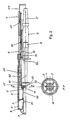
- Fig. 1 shows an autoinjection device in the form of a Injetationspens in longitudinal section.
- the pen has a hollow cylindrical, in the exemplary embodiment circular cylindrical housing with a needle guard 1 at its front end, an adjoining front Housing sleeve 2 and an adjoining rear housing sleeve 3 with a this front side final housing cap 4.
- the front housing sleeve 2 encloses a cylindrical container B, which in turn in a container holder 30 coaxial with a Center longitudinal axis of the housing is kept centered.
- the container holder 30 is also sleeve-shaped and runs forward in centering tongues, which against the peripheral edge of Press container B and center it in the front housing sleeve 2.
- the container holder 30 is slidable back and forth along the central longitudinal axis of the housing. When advancing the container holder 30, the container B held therein is moved with. In this case, one at a front end of the container B at an outlet arranged injection needle N after pushed and in the course of an autoinjection in and under the skin of a patient.
- a piston K along the central longitudinal axis of the container B is displaceable.
- a product contained in the container B in Embodiment, a drug liquid, such as insulin, through the outlet into and out of the injection needle N to dispense the product.
- a drug liquid such as insulin
- the container B is widened flange along its rear edge. Of the Container holder 30 is also widened accordingly at its rear end and with widened cross-section a piece far beyond the container sleeve-shaped continued.
- the container B is in the installed state with its rear widening at the shoulder surface of the container holder 30 facing this widening.
- An outer circumferential surface of the container holder 30 is of a as a return element 33rd surrounding compression spring, with a front end on a shoulder surface of the front housing half 2 rests and from there not quite up to a mating surface 31 protrudes, which is formed by the broadening of the container holder 30 on the container holder 30 and the aforementioned shoulder surface of the front housing sleeve 2 faces.
- the compression spring 33rd compressed and resilient between these two facing surfaces thereby the feed movement during insertion of the needle N from.
- the surface 31 abuts the Advancing against a shoulder surface, which is in the range of a stepped widening the front housing sleeve 2 is formed.
- the stop of the shoulder surface 31 of Container holder 30 defines a front position of the container B and thus the one Length with which the needle N in the front position of the container B on the front Edge of the housing protrudes, which at the same time, correct placement of the pen provided on the skin, the penetration depth of the needle N is specified.
- a drive device for advancing the container B and for advancing the Piston K in the container B is formed by a drive element designed as a compression spring fifth and an output member 10 is formed.
- the drive could also by means of a pressure medium respectively.
- the output member 10 is substantially sleeve-shaped with a rearward open husk, which is closed by a floor. At its front end the output member 10 is on the piston rod to a beyond the said bottom out comparatively short length continued sleeve-shaped.
- the sequel forms one Stamp 11 for pressing against the piston rod and advancing the piston K in Container B.
- the output member 10 is coupled to the container B.
- the output member 10 is coupled to a transmission member 20, which then acts directly on the container B.
- the transmission member 20 could also act directly on the container holder 30, in which case between the container holder 30th and the container B entrainment would be provided.
- the output member could Immediately press on a container or container holder to the needle advance.
- the transmission member 20 is formed by a sleeve body, in the rear Area formed by cross-sectional constriction is a circumferential shoulder 22, which as front pressure surface for a resilient ring 21 is used.
- the elastic ring 21 is in a on the outer circumferential surface of the output member 10 in the region of the punch 11 circumferential groove the output member 10 held against displacement secured.
- the Ring 21 may be formed as a closed flexible ring, preferably However, it is made of a hard material such as plastic or metal, and is on one Broken point, so that the there facing each other ends of the ring 21 a Pieces can be moved far towards each other and so the diameter of the ring can be reduced.
- the resilient ring 21, the shoulder 22 and the shoulder 22 facing wall 12 of the groove form a based on form and adhesion, releasable Coupling between the output member 10 and the transmission member 20.
- the ring 21 as Pressure and coupling means could also be used as a bead on the output member 10 or transmission member 20 may be formed, which then leak to the bendable in tongues would.
- the output member 10 is against the pressure of the drive element 5 in the in Fig. 1st illustrated starting position of a holding and release sleeve 6 by means of a holding at the holding and release sleeve 6 formed release latch 7 is held.
- the connection is through Eintex let the release tab 7 solved.
- the needle N which is exactly in Advancing direction, is pushed beyond the front edge of the needle guard 1 addition and penetrates the tissue.
- the advancement of the container B and thus the Penetration depth of the needle N are by striking the shoulder surface 32 of the container holder 30 limited to the housing-side mating surface.
- the container B takes now his front position.
- the shoulder 22 points in the feed direction obliquely or arcuately from the further rear to the narrower front cross-section of the Transmission element 20.
- the resilient ring 21 is round in cross section. Basically, the cross-sectional shape of the ring 21 and the course of the shoulder 22 only to tune to each other, that the resilient ring 21, the shoulder 22 is not already before reaching the front Override container position, including the coupling at least the advancing of the Container B reaction force occurring and required for piercing the needle Force must transmit, and that the coupling after reaching the front container position not blocked, but safely released.
- the vote of the coupling is when also the release as far as possible without jerk.
- the decrease of the driving force can also be compensated pneumatically.
- pneumatic Compensation would be between the lateral surfaces of the output member 10 and the Transfer member 20 enclosed space as far as possible hermetically sealed.
- guide ring 18 would be as Form sealing ring to the output member 10, which would form a piston itself.
- Further may be between the inner shell of the transfer member 20 and the opposite Surface of the punch 11 formed sliding surfaces may be formed as sealing surfaces.
- the spring 33 causes a cushioning and thus delay the feed movement of the Container holder 30 with the container B.
- put the container holder 30 and the Container B at the beginning of its advancing movement is not obstructed by the spring 33 Back stretch, since the shoulder 31 of the container holder 30 only after covering this predetermined distance passes in contact pressure to the spring 33.
- the feed movement over The remaining distance to the front container position is then compared to the force the drive element 5 slows down the lower restoring force of the spring 33. This will as desired, a rapid penetration of the needle with subsequently slowed down advancing speed achieved in the deeper tissue layers.
- On the front housing sleeve 2 trained stop tabs 2a hold the container holder 30 in its rear position.
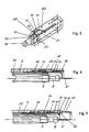
- Fig. 2 shows a second embodiment of an autoinjection device again in the form a pen in a longitudinal section and in a cross-section A-A.
- This pen will be the Drive connection between the output member and the container and the output member and the piston produced and released purely positive fit.
- the housing is also formed by a front housing sleeve 2 and a rear housing sleeve 3 formed.
- the needle guard 1 is in this embodiment in one piece on the formed front housing sleeve 2.
- a container holder 30 in which a filled with the product to be administered container B centered is held, slidably mounted along the housing longitudinal axis back and forth.
- the container holder 30 with a front Stop surface 31 driven against a housing-side stop, causing the front Position of the container B or the penetration depth of the needle N is defined.
- the two housing sleeves 2 and 3 are unscrewed, causing the Container B and the container holder 30 free from the transmission member 20 and the Container holder 30 under the pressure of the resetting element designed as a return spring 33 with a rear stop surface 31 against a housing-side stop surface in its rear position, the starting position, is pushed back. In this back Position, a new container B can be used. After screwing together the two housing sleeves 2 and 3, the pen of Fig. 2 is ready for the next injection.
- the output member 10 of the pen of FIG. 2 via a transfer member 20 to the container; likewise, the transmission member 20 may act on the container holder 30, which then take the container B.
- the feed of the Piston K in the container B is carried out by direct pressure of the punch 11 of the Output member 10 on the container B from the rear projecting piston rod, the abragend attached to the piston K from the rear or integral with the piston K is formed.
- the output member 10 is characterized by a solid cylindrical body with a stamp 11 formed with widened cross-section.
- the drive element 5 is in turn as a compression spring formed and surrounds a cylindrical shank part of the output member 10. It is in the Clamped starting position of the pen between the thickened punch 11 and ribs 9, to protrude from the rear housing sleeve 3 radially inwardly on the cylindrical shaft portion.
- the output member 10 is held by snapper 15 in its initial position.
- the transmission member 20 is characterized by a simple hollow cylindrical Sleeve, preferably a circular cylindrical sleeve, formed from the outer Projecting surface in a rear region, a cam 25 protrudes radially outward.
- a simple hollow cylindrical Sleeve preferably a circular cylindrical sleeve, formed from the outer Projecting surface in a rear region, a cam 25 protrudes radially outward.
- At the inner circumferential surface of the transmission member 20 is a in the longitudinal direction of the transmission member 20 extending, opening into the end face 23 release groove 24 except.
- the groove 24 is at least so large that the cam 13 of the abrasive member 10 in her can be included.
- the transmission member 20 is in a substantially also simple hollow cylindrical, preferably circular cylindrical sleeve longitudinally displaceable and rotatable about the longitudinal axis arranged.
- This sleeve forms a guide means 40 for the transmission member 20, such that a sliding movement of the transmission member 20 relative to the guide means 40 forced into a rotational movement of the transmission member 20 about its longitudinal axis is converted relative to the guide means 40, i. the sliding movement is superimposed a rotational movement.
- the guide means 40 is in the embodiment as independent sleeve formed, which is received in the housing against rotation and displacement is. It could in principle also with the housing, in the embodiment with the rear housing sleeve 3, be formed in one piece, which, however, the production consuming would shape.
- the relative rotation of the transmission member 20 relative to the guide means 40 and the in the housing torsionally straight driven output member 10 is connected by means of a between the Transmission member 20 and the guide means 40 formed slotted guide causes.
- the slide guide In training the slide guide is on the inner circumferential surface of the guide means 40th the cam 25 of the transmission member 20 opposite a guide groove 41 for except this cam 25.
- the filling with 41 has a rear straight groove portion 42 and this arc-shaped continuing, possibly simply oblique expiring second groove portion 43, i. the second groove portion 43 has a Transverse component to the feed direction of the transfer member 20. In the starting position If the cam 25 is in the groove portion 42 to lie.
- a trigger mechanism comprises an outer sleeve 4, a trigger button 7 and a Return spring 8 on.
- the outer sleeve 4 surrounds the rear region of the rear housing sleeve 3 and is on the outer circumferential surface of the rear housing sleeve 3 along the Longitudinal axis back and forth movable.
- the trigger button 7 is in a central opening of the rear end face of the outer sleeve 4 inserted. He penetrates this opening with a until near the snappers 15 of the output member 10 extending inner sleeve.
- the piercing of the needle N and the release of the product are made by pressing the Trigger button 7 in the longitudinal direction of the pen on the output member 10 and its snapper 15 causes.
- the inner sleeve of the release button 7 thereby over-pushes the rear ends the snapper 15, which thereby are bent elastically radially inwardly towards each other, whereby the latching connection with the housing-side ribs 9 is released.
- the pressure of the drive element 5 is of the shared output member 10, which with his cam 13 presses against the rear end face 23 of the transmission member 20, on the transmission member 20 transmitted, in turn, with its front face against a rear flange surface of the container B presses. With the front face of the the same flange presses the container B on the container holder 30, which in turn means of the return element 33 against a non-displaceable to the housing locking sleeve 60 presses.
- the pressing force of the remindstellelemnts 33 is opposite to that of the drive element 5 comparatively small, so that under the pressure of the drive element 5 the output member 10, the transmission member 20 and the container holder 30 with the container B are advanced along the housing longitudinal axis in the housing.
- the cam 25 of the transmission member 20 slides in its guide 41. Once the cam 25 moves in its advancing in the second groove portion 43, the Transfer member 20 forcibly because of the transverse component of the second groove portion 43 forced in a rotation about its longitudinal axis.
- the course of the guide groove 41 is chosen so that by the forced relative rotation relative to the housing and opposite the output member 10 in the transmission member 20 recessed release groove 24, the in the end face 23 opens, comes to rest in coverage to the cam 13.
- the output member 10 is the transmission member 20 decoupled.
- the course of the guide groove 41 is chosen so that the Cover is made as soon as the container holder 30 with its front stop surface 31 is on the housing to stop and thus the container B its front position occupies.
- the output member 10 With the decoupling or release, the output member 10, the transmission member 20 further advance under the pressure of the drive element 5. It presses against the piston rod, so that the piston K in the container B under the direct pressure of the output member 10 is advanced until the product is released is.
- the piercing of the needle N is desired by the course of the guide groove 41 established.
- the needle N By acting in a first part of the advancing movement of the transfer member runs straight in the feed direction and therefore the advancing of the transfer member 20th no resistance is opposed, the needle N initially pierces very quickly.
- the Penetration speed is slowed down further penetration, since the guide groove 41 then also transversely to the feed direction, in the Ausffihnmgsbeispiel helically, runs and accordingly, the transfer member 20 in the mecanicsabschriitt 43 during advancement a from the slope of the guide portion 43 dependent frictional force undergoes. additionally The speed at which the needle punctures, by the increasing restoring force of the return element 33 is reduced.
- FIGS. 4 and 5, together with FIG. 2, show the operation of the needle protection device, which prevents the needle N from being pulled out of the tissue freely protruding from the housing and be broken off and injuries in careless Can cause handling.
- the essential feature of the needle protection device is that for the purpose of puncturing the housing against sliding needle protective sleeve 50 is blocked after pulling out the needle in a needle protection position, so that it can no longer be pushed into the housing; an outside sliding of the Housing would also be conceivable.
- Fig. 4 shows the front part of the pen of Fig. 2 in the front position of the container B.
- the needle guard 50 is against the force of the return element 51 in their rearmost Displacement position of the housing sleeve 2 has been pressed against.
- the needle N protrudes the desired length of the housing and the needle guard 50 before.
- the needle guard 50 has a rear abutment surface and a front abutment surface on, the displacement of the needle protection sleeve 50 relative to the front housing sleeve 2 limit in the feed direction and against the feed direction.
- the needle guard 50 moves over the locking sleeve 60, which at its front end has an obliquely or arcuately outwardly projecting hook 62.
- the needle protective sleeve 50 has in an inner shell region, with which it slides over the hook 62, The length of their maximum displacement approximately corresponding to a slightly widened Inside diameter.
- a transition area 52 between this widened front Inner cross-section to the subsequent inner cross-section is chamfered, so that the needle protection sleeve 50 under the pressure of the return element 51 to behind the transition area 52 can slide over the hook 62.
- the needle guard 50 is behind the Transition region 52 provided in a central region with longitudinal slots 53, whose front end surfaces 54, as best seen in Fig. 5, stop surfaces for each form one of the hooks 62.
- the locking sleeve 60 is arranged distributed in several evenly distributed over the Hommescnpatented elastically yielding tongues 61, at the free front ends of the Hooks 62 are formed.
- the container holder 30 runs to its free front end also in tongues 34 off.
- Tongues 34 By advancing the Be 1969nishalters 30 come Tongues 34 to lie under the tongues 61 of the locking sleeve 60.
- Each of the tongues 61 becomes like that radially inwardly supported and can no longer radially in the front container position be bent inwards.
- the tongues 61 are not only supported by the tongues 34, but additionally pressed radially outward.
- the tongues 34 are compared with the Tongues 61 rigidly formed or can in first approximation to these tongues 61 opposite to be assumed as rigid.
- the needle shield sleeve 50 After pulling out the needle, the needle shield sleeve 50 by the return element 51 again pushed off. It overshadows because of the oblique course of the Surface 52 and / or the corresponding skew of the hook 62 this hook 62, its expiring tip is also elastic yielding. However, as soon as the needle protection sleeve 50 has advanced so far that their stop surface 54 in the feed direction seen before the hook 62 comes to rest, it is by the against the stop surface 54 lying on stop hook 62 locked against pushing back. The hook 62 and the needle guard sleeve 50 are pointing perpendicular to the direction of displacement Stop surfaces to each other. The needle N becomes in the safety position shown in FIG protected after injection by the needle guard 50.
- the container holder 30 is thus at the same time as a sliding support for the used elastic blocking means 62 and fulfilled according to the invention, the dual function of Holding the container and locking the needle guard 50.
- the needle guard does not assume the inventive design of the autoinjection device, although it is most preferably used in combination therewith. She is the same with advantage in generic autoinjection devices and even unchanged at Injection devices used in which the insertion of the needle by advancing the Container to the housing is done manually.
- Figure 6 shows in longitudinal section and above in a plan view of an autoinjection, at the coupling of the output member 10 with the container B and the piston K on Force and form closure is based.
- the coupling is in effect the same as that of the pen of FIG. 1 comparable. In the following is always on the registered in plan view cross sections and the detail X directed.
- the container B of the pen of FIG. 6 is a so-called double-chamber ampoule, in the two polymer components in two chambers arranged one behind the other, in the delivery state of the container B by a front piston K1 from each other are separated, only by advancing a rear piston K2 against the front piston K1 are mixed together.
- In the delivery state of the front Chamber is generally a powdered drug while in between stored a carrier liquid the chamber formed in the two pistons K1 and K2 becomes.
- the housing again has a front and a rear housing sleeve 2 and 3, which are firmly connected to each other, for example by screwing or plugging.
- a cap 4 is inserted into the rear housing sleeve 3.
- the front housing sleeve 1 is extended to from by a Nadelschuz 1 and a Nadelschhülse 50 ', which is retractable for piercing the needle N against a restoring force and after the injection resumes the advanced position.
- the container B is inserted into a container holder 30 to the stop and centered held.
- the container holder 30 is against the force of the return element 33 in the housing be advanced.
- the advancement of the rear piston K2 is when assembling the front Housing sleeve 2 and the rear housing sleeve 3 causes.
- a as Sleeve body trained mixing member 20 in the rear housing sleeve 3 against rotation added.
- the mixing member 20 has a front sleeve portion with an outer diameter, which is smaller than the inner diameter of the container B, and a towards this front sleeve area widened rear sleeve area.
- One Transition between these two sleeve portions is considered to be radial from the front sleeve portion protruding shoulder 28 is formed.
- the shoulder 28 is formed circumferentially; she However, it can also be formed by at least one radially projecting web.
- the drive device is arranged, which is the drive element 5 in the form of a compression spring and the rod-shaped output member 10, the is straightened in the housing.
- the drive element 5 is between the webs 9 and a the webs 9 in the feed direction opposite facing, circumferential shoulder surface of the output member 20 clamped.
- the output member 10 is about a central longitudinal axis of the housing, with its own Center longitudinal axis coincides, between two rotational positions back and forth rotatable added.
- a housing extending Dosing sleeve D provided. In its rear area, which is in the dosing sleeve D protrudes, the output member 10 in the feed direction extending guide grooves on, in the one in the cap 4 protruding, the cap 4 opposite rotatable, displaceable guide sleeve 6a and a rotatable in the housing and
- the guide sleeve 6a is with the metering sleeve D connected secured against rotation, as best seen in section H-H is.
- the guide sleeve 6a serves to transmit the rotational movement of the dosing sleeve D. the output member 10.
- the display sleeve 8, the secured against rotation with the output member 10th is connected, is used to display the rotational position of the output member 10 and thus the Display of the set dose amount. It is for this purpose at its outer periphery provided with markers, in the exemplary embodiment with two markings for each one of two rotational end positions of the output member 10. The markings can be replaced by a Housing opening are read through.
- the display sleeve 8 and the guide sleeve 6a serve together with the mixing member 20 as a straight guide for the output member 10th
- the output member 10 is in the illustrated rear starting position by a locking and Release mechanism held.
- the locking and release mechanism has a triggering means 7a in the form of a release button, the transversely to the direction of displacement of the output member 10th acts on a blocking means 7b.
- the structure and operation of the locking and release mechanism is best in the synopsis of the longitudinal section and the cross-section F-F to recognize.
- the blocking means 7b is formed by a sleeve body with a passage opening, which is penetrated by the output member 10.
- the blocking means 7b is for the purpose of his Straight guide transversely to the feed and longitudinal direction of the output member 10 between two straight webs of the housing out. These two housing bars facing each Accordingly, the sleeve body of the blocking means 7b has straight outer surfaces.
- the Through opening of the locking means 7b is larger than the outer diameter of the penetrating Output member 10.
- the output member In the blocking position, the output member abuts 10 with a formed by a thickening shoulder 29 against a rear end face the blocking means 7b.
- the output member 10 is released from the locking means 7b and can under advance the pressure of the drive element 5 in the longitudinal direction.
- a safety device ensures that the triggering means 7a only then actuated and Thus, the output member 10 can be released when a container B in the Housing has been inserted.
- the safety device comprises a trigger lock body 70 and a compression spring 19.
- the trigger lock body 70 has a central sleeve portion projecting from the front in the longitudinal direction of two webs 70a (section E-E).
- the two webs 70a project through two correspondingly shaped slots in the shoulder 28 of the Mixing member 10 and abut the rear edge of the container B.
- From the middle Sleeve portion of the trigger lock body 70 protrudes a third web 70b in the longitudinal direction back off. This third land 70b extends through the triggering means 7a, as best shown in FIG Combination of the longitudinal section with the two sections F-F and G-G can be seen.
- the third web 70b of the release lock body 70 has a longitudinal slot.
- This longitudinal slot moves a radially inwardly projecting rib 7d of the triggering means 7a upon actuation of the triggering means 7a on, when the slot of the release lock body 70 on the same height as the inner rib 7d of the triggering means 7a.
- the third land 70b Seen in the longitudinal direction behind the slotted area, is again as a closed land eye forms.
- the compression spring 19 tensioned is also known between the housing-side web 9 and one of the inner circumferential surface of the central sleeve portion of the trigger lock body 70 inwardly projecting shoulder.
- the mixing member 20 assumes a double function the function of a transfer element and will accordingly be described below as a and transfer member 20.
- the output member 10 has accordingly only a the entrainment of the mixing and transfer member 20 causing contact surface 17 for the ring 21 on.
- the pressure surface 17 forms a first coupling means, one through the Groove of the mixing and transfer member 20 formed contact surface 27 is a second and the ring 21 a third coupling means.
- the mixing and transmission member 20 and the output member 10 form in one within of the container B arranged a metering device.
- the mixing and transfer element 20 is located in a behind the first coupling means 17 for this purpose Inner jacket area provided with a recess.
- the recess has two in Advancing direction extending grooves 25 and 26, the angle offset parallel to each other are arranged.
- the grooves 25 and 26 are of different lengths in the feed direction.
- the kuüere groove 25 is formed as a blind groove in the lateral surface, and the longer groove 26th is in the feed direction through the rear web of the receptacle for the third coupling means 21 limited.
- the grooves 25 and 26 At their rear ends open the grooves 25 and 26 on the same Height with respect to the feed direction in a widening of the recess, such as best in a synopsis of the longitudinal section with the sections C-C, D-D and E-E too recognize.
- the broadening of the recess extends to the rear face of the front sleeve portion of the mixing and transfer element 20. The expiring there, facing each other side walls of the broadening are ever by one of the two grooves 25 and 26 extends in the feed direction.
- the output member 10 is provided with a radially projecting cam 16.
- the cam 16 engages in the broadening of the recess of the Mixing and transfer member 20 a.
- the recess with the two grooves 25 and 26th forms a first dosing and the cam 16 a second dosing of the metering device.
- a first metering position of the cam 16 In a first metering position of the cam 16 is in alignment with the groove 25 in the feed direction extending first side wall of widening, and in the second metering position of the cam 16 is aligned with the groove 26 in the feed direction extending second side wall of the broadening of the recess.
- the output member 10 is in the initial state of Injection device back and forth about its longitudinal axis rotatable.
- the two side walls of the Wide groove define the two rotational and metering positions of the output member 10, and the Lengths of the two narrow grooves 25 and 26 define the amount of one injection distributable active ingredient solution.
- the broadening of the recess in the mixing and transmission member 20 could also up be extended to the end of the short groove 25 in the feed direction, so that the recess would have a simple staircase shape in the feed direction.
- the autoinjection apparatus For performing auto-injection, the autoinjection apparatus with the front, the Housing or the front needle guard 1 against retractable needle guard 50 'on a tissue surface, especially the human skin, put on. By Pressure against the tissue surface, the needle guard 50 'to a posterior Position pushed back relative to the housing.
- the injection needle N which at the outlet on of the container B pointing in the direction of feed is firmly attached, is still from the needle guard 1 and the over-pushed needle protection sleeve 50 'to over its front Tip also surrounds and thus does not touch the tissue surface.
- the form and adhesion between the output member 10 and the mixing and transmission member 20 is sufficient strong, to cause the entrainment of the mixing and transmission member 10, which in turn by means of his shoulder 28 against the container holder 30 and the container B pressing this relative to the housing and against the restoring force of the return element 33 up to advances a front position defined by a housing-side stopper 31a becomes.
- the feed movement of the output member 20 is in the first metering position by the front end of the groove 25 limited. In the first metering position is the payout terminated when the cam 16 at this circumferentially extending groove wall abuts.
- the injection device for a second injection After pulling out the needle N, the injection device for a second injection readied.
- the output member 10 is first the mixing and transmission member 20 to retract opposite to the feed direction.
- the driven member 10 At the front End, the driven member 10 has a punch 11 in the form of a flange-like widening on.
- the output member 10 presses with the Plunger 11 on the rear piston K2, and upon retraction pushes the rear, circumferential shoulder surface of the punch 11 against the of the inner surface of the Mixing and transmission member 20 projecting web, which is the front wall of the Receiving groove for the third coupling means 21 forms.
- the Output member 10 Upon further withdrawal of the Output member 10 is thereby taken along the mixing and transfer member 20, i.
- the output member 10 is rotated to its second metering position, in which the cam 16 is in alignment with the groove 26. In this position, the output member 10 are advanced so far relative to the mixing and transfer member 20, that the remaining in the container remaining amount of the drug solution in an operation of the Drive means, i. an actuation of the triggering means 7, is distributed.
- the Feed movement is limited by a revolving web, which is the rear wall the receiving groove for the third coupling means 21 forms.
Landscapes
- Health & Medical Sciences (AREA)
- Animal Behavior & Ethology (AREA)
- Heart & Thoracic Surgery (AREA)
- General Health & Medical Sciences (AREA)
- Biomedical Technology (AREA)
- Public Health (AREA)
- Hematology (AREA)
- Life Sciences & Earth Sciences (AREA)
- Veterinary Medicine (AREA)
- Anesthesiology (AREA)
- Engineering & Computer Science (AREA)
- Vascular Medicine (AREA)
- Infusion, Injection, And Reservoir Apparatuses (AREA)
- Hydrogenated Pyridines (AREA)
- Medicines That Contain Protein Lipid Enzymes And Other Medicines (AREA)
- Acyclic And Carbocyclic Compounds In Medicinal Compositions (AREA)
- Threshing Machine Elements (AREA)
- Injection Moulding Of Plastics Or The Like (AREA)
Abstract
Description
Autoinjektionsgeräte dienen zur Verabreichung von Produkten, insbesondere medizinisch oder kosmetisch wirksamen Flüssigkeiten. Dabei wird eine Injektionsnadel, durch die das Produkt verabreicht wird, nach Auslösen eines Antriebsmechanismus automatisch ein vorgegebenes Wegstück weit in ein Gewebe hineingestochen.Autoinjection devices serve to administer products, in particular medically or cosmetically active liquids. This is a hypodermic needle through which the Product administered automatically after triggering a drive mechanism given part of the path pierced far into a tissue.
Ein Autoinjektionsgerät, wie die Erfindung es betrifft, umfaßt zumindest ein Gehäuse, ein vom Gehäuse verschiebbar aufgenommenes Behältnis, aus dem ein zu verabreichendes Produkt durch Vorschieben eines Kolbens durch eine an einem Auslaß des Behältnisses angeordnete Nadel ausgeschüttet wird, und ein vom Gehäuse verschiebbar aufgenommenes Abtriebsglied einer Antriebseinrichtung, das bei einer Autoinjektion zum Einstechen der Nadel das Behältnis dem Gehäuse gegenüber in Vorschubrichtung des Kolbens bis zu einer vorgegebenen vorderen Position und zum Ausschütten des Produkts den Kolben im Behältnis vorschiebt. Sobald das Behältnis seine vordere Position bei einer Autoinjektion eingenommen hat, ist die Nadel um eine vorgegebene Wegstrecke zusammen mit dem Behältnis vorgeschoben worden, wobei mit der Vorgabe der Wegstrecke auch im wesentlichen die Eindringtiefe der Nadel vorgegeben ist. An autoinjection device, as the invention relates, comprises at least one housing From the housing slidably received container from which to be administered Product by advancing a piston through one at an outlet of the container arranged needle is distributed, and a slidably received by the housing Output member of a drive device, which in an autoinjection for piercing the Needle the container opposite the housing in the feed direction of the piston to a predetermined forward position and for pouring the product, the piston in the container advances. Once the container has taken its front position during an autoinjection has, the needle is a predetermined distance together with the container been advanced, with the specification of the path also essentially the Penetration depth of the needle is specified.
Derart ausgebildete Autoinjektionsgeräte sind aus der US-PS 159,192, der EP 0 516 473 B1 und der US-PS 5,643,214 bekannt.Such trained autoinjection devices are known from US-PS 159.192, EP 0 516 473 B1 and US Pat. No. 5,643,214.
Bei den bekannten Autoinjektionsgeräten erfolgt der Vorschub des Behältnisses mit der daran angebrachten Nadel durch Andruck des Abtriebsglieds auf den Kolben.In the known autoinjection devices, the advance of the container with the attached needle by pressing the output member on the piston.
Die Erfindung hat es sich zur Aufgabe gemacht, ein Autoinjektionsgerät zu schaffen, bei dem sichergestellt ist, daß zu verabreichendes Produkt erst ausgeschüttet wird, wenn die Injektionsnadel bei einem Einstechen in ein Gewebe vollständig vorgesto&n worden ist.The invention has set itself the task of creating an autoinjection device, in it is ensured that the product to be administered is distributed only when the Injection needle has been completely vorsto in a puncture in a tissue.
Nach der Erfindung ist das Abtriebsglied bei einem Autoinjektionsgerät der vorbeschriebenen Art bis zum Erreichen der vorderen Position des Behältnisses vom Kolben entkoppelt und wird bei Erreichen der vorderen Position des Behältnisses von dem Behältnis entkoppelt und zum Vorschieben des Kolbens im Behältnis mit dem Kolben gekoppelt. Das Vorschieben des Behältnisses zum Einstechen der Nadel wird nicht mittels des Kolbens bewirkt, d.h. es besteht während dieser Bewegungsphäse keine Antriebsverbindung zwischen dem Abtriebsglied und dem Kolben. Hierdurch wird sicher ausgeschlossen, daß bereits während des Vorschiebens des Behältnisses Produkt durch eine etwaige, wenn auch kleine, Vorschubbewegung des Kolbens im Behältnis, d.h. relativ zum Behältnis, ausgeschüttet wird. Indem in der vorderen Position des Behältnisses das Abtriebsglied vom Behältnis entkoppelt und erst jetzt mit dem Kolben gekoppelt wird, wird der Kolben frühestens dann im Behältnis vorgeschoben, wenn die Nadel bis in die gewünschte Tiefe in das Gewebe eingestochen worden ist. Die antriebsseitige Trennung der Vorschubbewegung des Behältnisses und der Vorschubbewegung des Kolbens im Behältnis erhöht die Genauigkeit der Dosierung, da ein Andruck auf den Kolben nicht bereits während des Vorschiebens des Behältnisses ausgeübt wird und dadurch Produkt vorzeitig ausgeschüttet werden kann.According to the invention, the output member is in an autoinjection device of the above Art decoupled until reaching the front position of the container from the piston and is decoupled when reaching the front position of the container from the container and coupled to advance the piston in the container with the piston. The advancing the container for piercing the needle is not effected by means of the piston, i.e. there is no drive connection between them during this movement phase the output member and the piston. This will certainly exclude that already during the advancement of the container product by any, albeit small, Advancing movement of the piston in the container, i. relative to the container, distributed becomes. By in the front position of the container, the output member from the container decoupled and only now coupled with the piston, the piston is then at the earliest advanced in the container when the needle is down to the desired depth in the tissue has been stabbed. The drive-side separation of the feed movement of the container and the advancing movement of the piston in the container increases the accuracy of Dosage, as a pressure on the piston is not already during the advancement of the Container is exercised and thereby product can be distributed prematurely.
Das Abtriebsglied kann zum Vorschieben des Behältnisses unmittelbar auf das Behältnis wirken. The output member can be used to advance the container directly to the container Act.
Vorzugsweise ist ein Übertragungsglied vorgesehen, das von dem Abtriebsglied bei einem Vorschieben mitgenommen wird, dabei auf das Behältnis und/oder einen Behältnishalter wirkt und so das Behältnis vorschiebt. Das Übertragungsglied kann auch ein Behältnishalter sein, wird vorteilhafterweise jedoch als davon separates Teil ausgebildet.Preferably, a transmission member is provided by the output member in a Advance is taken, while the container and / or a container holder acts and so the container advances. The transmission member may also be a container holder However, it is advantageously formed as a separate part thereof.
Zwischen dem Abtriebsglied und dem Übertragungsglied besteht die lösbare Kopplung. Nach dem Lösen der Kopplung in der vorderen Behältnisposition bewirkt ein weiteres Vorschieben des Abtriebsglieds, nämlich zum Vorschieben des Kolbens, kein weiteres Vorschieben des Übertragungsglieds mehr. Das Abtriebsglied ist jetzt zumindest in Bezug auf seine eigene Vorschubbewegung vom Übertragungsglied frei. Es drückt nur noch gegen den Kolben und schiebt diesen im Behältnis dadurch vor. Vorzugsweise ist das Übertragungsglied vom Gehäuse verschiebbar in und gegen die Vorschubrichtung des Kolbens aufgenommen.Between the output member and the transmission member is the releasable coupling. After releasing the coupling in the front container position causes another Advance the output member, namely for advancing the piston, no further Advance the transmission link more. The output member is now at least in relation free on its own feed motion from the transfer link. It only pushes against the piston and pushes it in the container before. Preferably, the transmission member from the housing displaceable in and against the feed direction of the piston added.
In einer ersten Ausführungsform werden das Abtriebsglied und das Behältnis bzw. das Übertragungsglied rein formschlüssig miteinander gekoppelt. In einer zweiten Ausführungsform schließt die Kopplung eine kraftschlüssige Verbindung zwischen dem Abtriebsglied und dem Behältnis bzw. dem Übertragungsglied zumindest mit ein.In a first embodiment, the output member and the container or the Transfer element purely form-fitting coupled together. In a second embodiment the coupling closes a frictional connection between the output member and the container or the transmission member at least one.
Eine formschlüssige Verbindung des Abtriebs- und des Übertragungsglieds kann dadurch gebildet werden, daß das Abtriebsglied mit einem ersten Kopplungsmittel und das Übertragungsglied mit einem zweiten Kopplungsmittel verbunden ist und diese beiden Kopplungsmittel miteinander eine Riegel-Schloß-Verbindung bilden, die in dem Moment gelöst wird, in dem das Behältnis seine vordere Position erreicht. Das erste Kopplungsmittel ist vorzugsweise ein starr mit dem Abtriebsglied verbundener Nocken, der durch Andruck gegen eine Anschlagfläche einen Vorschub des Übertragungsglieds bewirkt. Im Zuge der Entriegelung und der damit einhergehenden Entkopplung des Abtriebs- vom Übertragungsglied wird der in der Art eines Riegels wirkende Nocken mit einer in die Anschlagfläche mündenden Ausnehmung in Deckung gebracht, so daß der Nocken nicht mehr länger gegen die Anschlagfläche drückt; er fällt sozusagen in sein Schloß. Das Abtriebsglied kommt frei vom Übertragungsglied, wodurch auch die Kopplung mit dem Behältnis gelöst wird, und kann sich nun auch relativ zum Übertragungsglied weiter vorwärtsbewegen. Im Zuge dieser Relativbewegung gegenüber dem Übertragungsglied gelangt das Abtriebsglied in Andruck gegen den Kolben, wodurch die Kopplung von Abtriebsglied und Kolben hergestellt wird. Der Riegel könnte auch mit dem Übertragungsglied und das Schloß könnte auch mit dem Abtriebsglied verbunden sein.A positive connection of the output and the transmission member can thereby are formed, that the output member with a first coupling means and the transmission member is connected to a second coupling means and these two coupling means Together form a bolt-lock connection, which solved in the moment becomes, in which the container reaches its front position. The first coupling agent is Preferably, a rigidly connected to the driven member cam, the pressure by against a stop surface causes a feed of the transfer member. In the course of Unlocking and the associated decoupling of the output from the transmission element is the acting in the manner of a bolt cam with a in the stop surface opening recess brought into coincidence, so that the cam is no longer against pushes the stop surface; he falls into his castle, so to speak. The output member comes free from the transfer member, whereby the coupling with the container is released, and can now also move forward relative to the transmission element. In the course of this Relative movement relative to the transmission member, the output member comes in contact pressure against the piston, whereby the coupling of output member and piston is made. The latch could also be with the transmission link and the lock could also be with the Be connected output member.
Die Entkopplung des Abtriebsglieds vom Übertragungsglied wird vorzugsweise durch eine Drehung eines dieser beiden Glieder relativ zum jeweils anderen bewirkt. Die Relativdrehung erfolgt vorzugsweise um eine zur Verschieberichtung parallele Drehachse. Die Relativdrehung wird durch das Vorschieben zwangsweise erzeugt, vorzugsweise durch eine zwischen dem zu verdrehenden Glied und dem Gehäuse ausgebildete Kulissenführung. Obgleich eine hierbei erzeugte Reibungskraft zur gezielten Beeinflussung der Vorschubgeschwindigkeit des Abtriebs- und des Übertragungsglieds genutzt werden kann, wirkt die Kopplung an sich, d.h. das Blockieren und das lösen, rein formschlüssig.The decoupling of the output member from the transmission member is preferably by a Rotation of one of these two limbs relative to the other causes. The relative rotation Preferably takes place about a parallel to the direction of rotation axis of rotation. The Relative rotation is forcibly generated by the advance, preferably by a formed between the member to be twisted and the housing link guide. Although a friction force generated in this case for specifically influencing the feed rate the output and the transmission member can be used, the acts Coupling per se, i. the blocking and the release, purely positive.
In einer zweiten Ausführungsform wird eine form- und kraftschlüssig wirkende Kopplung zum Koppeln und Entkoppeln des Abtriebsglieds mit und von dem Behältnis sowie mit und von dem Kolben verwendet. Auch in dieser Ausführungsform ist die Kopplung vorzugsweise zwischen dem Abtriebsglied und einem Übertragungsglied ausgebildet, obgleich auch eine Kopplung unmittelbar mit dem Behältnis denkbar wäre.In a second embodiment, a positive and non-positive acting coupling for coupling and decoupling the output member with and from the container and with and used by the piston. Also in this embodiment, the coupling is preferable formed between the output member and a transmission member, although also a coupling directly with the container would be conceivable.
Die Kopplung wird vorzugsweise durch eine Schnappverbindung gebildet. Beim Vorschieben des Abtriebsglieds drückt ein Schnapper gegen eine Andruckfläche und schiebt dadurch das Behältnis vor. Wenn das Behältnis seine vordere Position erreicht hat, in der es dem Gehäuse gegenüber auf Anschlag liegt, wird die Schnappverbindung durch die weiterhin auf das Abtriebsglied wirkende Antriebskraft gelöst. Das Abtriebsglied wird mit dem Kolben gekoppelt und frei vom Behältnis bzw. frei vom Übertragungsglied weiter vorgeschoben. Ein leichter Stoß bei Erreichen der vorderen Behältnisposition kann durchaus unterstützend wünschenswert sein. The coupling is preferably formed by a snap connection. When advancing of the output member presses a snapper against a pressure surface and pushes thereby the container before. When the container has reached its front position, in the it is the housing opposite to stop, the snap connection by the further solved driving force acting on the driven member. The output member is with coupled to the piston and free from the container or free from the transfer element on advanced. A slight shock when reaching the front container position may well supportive desirable.
Zumindest eines der die Kopplung bildenden Mittel ist nachgiebig ausgebildet, vorzugsweise elastisch nachgiebig. Ein oder mehrere Schnapper können unmittelbar am Abtriebsglied ausgebildet sein, das damit gegen eine Andruckfläche des Behältnisses oder des Übertragungsglieds drückt, falls ein solches verwendet wird. Solche Schnapper können auch am Übertragungsglied vorgesehen sein.At least one of the coupling forming means is resilient, preferably elastically yielding. One or more snapper can directly on the output member be formed, which thus against a pressure surface of the container or the Transmitter expresses, if one is used. Such snapper can also be provided on the transmission member.
Besonders bevorzugt wird zur Ausbildung der Kopplung ein drittes Kopphmgsmittel mit einbezogen, das dann allein nachgiebig, vorzugsweise elastisch nachgiebig, ausgebildet ist. Vorteilhafterweise ist das dritte Kopplungsmittel ein nachgiebiger Ring, insbesondere ein Federring, der zwischen zwei einander gegenüberliegenden Flächen des Abtriebs- und des Übertragungsglieds eingeklemmt ist, und eine dieser beiden Andrucldlächen überschiebt, sobald das Behältnis seine vordere Position erreicht hat.Particularly preferred is to form the coupling, a third Kopphmgsmittel with included, which is then solely yielding, preferably elastically yielding, is formed. Advantageously, the third coupling means is a resilient ring, in particular a Spring washer, which between two opposite surfaces of the output and Transfer member is clamped, and one of these Andrucldlächen überiebt, once the container has reached its front position.
Die Erfindung kann mit Vorteil auch bei Autoinjektionsgeräten Verwendung finden, bei denen das Behältnis durch eine sogenannte Mehrkammerampulle gebildet wird. Durch solche Mehrkammerampullen wird das zu verabreichende Produkt erst durch Mischung von Inhalten der mehreren voneinander separierten Kammern beim Zusammensetzen des Geräts erhalten. Jede der hintereinander angeordneten Kammern wird rückwärtig mittels eines im Behältnis verschiebbaren Kolbens abgeschlossen. Zum Durchmischen wird ein Mischglied gegen den hintersten Kolben gedrückt und schiebt bei seinem Vorschieben im Behältnis jeden der Kolben nach vorne bis zum vordersten Kolben. Beim Vorschieben wird bzw. werden Verbindungen zur jeweils benachbart vorderen Kammer hergestellt, so daß ein Inhalt der hinteren Kammer jeweils in die benachbart davorliegende Kammer verdrängt wird.The invention can also be used with advantage in autoinjection devices where the container is formed by a so-called multi-chamber ampoule. By Such multi-chamber ampoules, the product to be administered only by mixing Contents of the several separate chambers when assembling the device receive. Each of the successively arranged chambers is rearward by means of a in Container of sliding piston completed. For mixing is a mixing element pressed against the rearmost piston and pushes in its advance in the container each of the pistons forward to the foremost piston. When advancing or Connections are made to each adjacent front chamber, so that a Contents of the rear chamber displaced in each case in the adjacent chamber in front becomes.
Nach der Erfindung bildet das an sich bekannte Mischglied, das insbesondere ein Mischrohr ist, nun gleichzeitig auch das Übertragungsglied zum Vorschieben des Behältnisses. Dem Mischglied wird erfindungsgemäß eine Doppelfunktion zugewiesen. Konsuuktiv wird dies vorzugsweise dadurch erreicht, daß das Mischglied einen radial nach außen abragenden Steg, vorzugsweise in Form einer umlaufenden Schulter, aufweist, mit dem es gegen die hintere Stirnfläche des Behältnisses oder, falls dies bevorzugt wird, gegen eine rückwärtige Andruckfläche eines Behältnishalters drückt, der bei seiner mittels des Mischglieds erzwungenen Vorwärtsbewegung das Behältnis mitnimmt. Auch die vordere Position des Behältnisses wird vorzugsweise durch Anschlag eines solches Behältnishalters gegen das Gehäuse definiert.According to the invention, the mixing member known per se, which in particular forms a mixing tube is, now also the transfer member for advancing the container. the Mixing member is assigned a dual function according to the invention. Consuuktiv becomes this preferably achieved in that the mixing member projecting radially outward Web, preferably in the form of a circumferential shoulder, with which it against the rear face of the container or, if preferred, against a rear one Pressing surface of a container holder presses, which enforced in his by means of the mixing member Forward movement takes the container. Also the front position of the Container is preferably by stopping such a container holder against the Housing defined.
Das Gehäuse kann sowohl das Behältnis als auch die gesamte Antriebseinrichtung umhüllen, vorzugsweise die Form einer Hülse aufweisen, dient jedoch in seiner allgemeinsten Ausbildung lediglich als Basisteil, gegenüber dem die Verschiebebewegung des Behältnisses und die Verschiebebewegung des Abtriebsglieds der Antriebseinrichtung erfolgen und ist daher nicht ausschließlich, obgleich bevorzugt, als umhüllendes Gehäuse zu verstehen.The housing can envelop both the container and the entire drive device, preferably in the form of a sleeve, but serves in its most general form merely as a base part, opposite to the sliding movement of the container and the displacement movement of the output member of the drive means is and is therefore not exclusively, although preferred, to be understood as an enclosing housing.
Ausführungsbeispiele der Erfindung werden nachfolgend anhand von Figuren erläutert. Es zeigen:
- Fig. 1
- ein Autoinjektionsgerät mit form- und kraftschlüssiger Kopplung,
- Fig. 2
- ein Autoinjektionsgerät mit formschlüssiger Kopplung,
- Fig. 3
- das Übertragungsglied des Geräts nach Fig. 2,
- Fig. 4, 5
- die Sperre für die Nadelschutzhülse des Geräts nach Fig. 2 und
- Fig. 6
- ein Autoinjektionsgerät mit einer Zweikammerampulle und einem als Übertragungsglied ausgebildeten Mischrohr.
- Fig. 1
- an autoinjection device with positive and non-positive coupling,
- Fig. 2
- an autoinjection device with positive coupling,
- Fig. 3
- the transmission element of the device according to FIG. 2,
- Fig. 4, 5
- the lock for the needle guard of the device of FIG. 2 and
- Fig. 6
- an autoinjection device with a two-chamber ampule and a mixing tube designed as a transfer member.
Fig. 1 zeigt ein Autoinjektionsgerät in Form eines Injektionspens im Längsschnitt.Fig. 1 shows an autoinjection device in the form of a Injektionspens in longitudinal section.
Der Pen weist ein hohlzylindrisches, im Ausführungsbeispiel kreiszylindrisches Gehäuse auf
mit einem Nadelschutz 1 an seinem vorderen Ende, einer daran anschließenden vorderen
Gehäusehülse 2 und einer sich daran anschließenden hinteren Gehäusehülse 3 mit einer
diese stirnseitig abschließenden Gehäusekappe 4. Die vordere Gehäusehülse 2 umschließt
ein zylindrisches Behältnis B, das seinerseits in einem Behältnishalter 30 koaxial zu einer
Mittellängsachse des Gehäuses zentriert gehalten wird. Der Behältnishalter 30 ist ebenfalls
hülsenförmig und läuft nach vorne in Zentrierzungen aus, die gegen den Umfangsrand des
Behältnisses B drücken und dieses in der vorderen Gehäusehülse 2 zentrieren. Der Behältnishalter
30 ist entlang der Mittellängsachse des Gehäuses hin und her gleitverschiebbar.
Beim Vorschieben des Behältnishalters 30 wird das darin gehaltene Behältnis B mit verschoben.
Dabei wird eine an einem vorderen Ende des Behältnisses B an einem Auslaß
angeordnete Injektionsnadel N nach vom geschoben und im Zuge einer Autoinjektion in
und unter die Haut eines Patienten gestochen.The pen has a hollow cylindrical, in the exemplary embodiment circular cylindrical housing
with a
Im Behältnis B ist ein Kolben K entlang der Mittellängsachse des Behältnisses B verschiebbar. Durch Vorschieben des Kolbens K wird ein im Behältnis B enthaltenes Produkt, im Ausführungsbeispiel eine Medikamentflüssigkeit, beispielsweise Insulin, durch den Auslaß in und durch die Injektionsnadel N hindurch zum Ausschütten des Produkts verdrängt. Vom Kolben K ragt rückwärtig eine Kolbenstange über einen hinteren Behältnisrand hinaus ab.In the container B, a piston K along the central longitudinal axis of the container B is displaceable. By advancing the piston K, a product contained in the container B, in Embodiment, a drug liquid, such as insulin, through the outlet into and out of the injection needle N to dispense the product. from Piston K projects rearwardly from a piston rod beyond a rear container edge.
Das Behältnis B ist entlang seines rückwärtigen Randes flanschartig verbreitert. Der
Behältnishalter 30 ist an seinem rückwärtigen Ende entsprechend ebenfalls verbreitert und
mit verbreitertem Querschnitt ein Stück weit über das Behältnis hinaus hülsenförmig
fortgeführt. Das Behältnis B liegt im eingebauten Zustand mit seiner rückwärtigen Verbreiterung
an der dieser Verbreiterung zugewandten Schulterfläche des Behältnishalters 30.
Eine äußere Mantelfläche des Behältnishalters 30 ist von einer als Rückstellelement 33
dienenden Druckfeder umgeben, die mit einem vorderen Ende an einer Schulterfläche der
vorderen Gehäusehälfte 2 anliegt und von dort nicht ganz bis zu einer Gegenfläche 31 ragt,
die durch die Verbreiterung des Behältnishalters 30 am Behältnishalter 30 gebildet wird und
der vorgenannten Schulterfläche der vorderen Gehäusehülse 2 zugewandt ist. Beim Vorschieben
des Behältnishalters 30 und damit des Behältnisses B wird die Druckfeder 33
zwischen diesen beiden einander zugewandten Flächen zusammengedrückt und federt
dadurch die Vorschubbewegung beim Einstechen der Nadel N ab. Die Fläche 31 stößt beim
Vorschieben gegen eine Schulterfläche, die im Bereich einer stufenförmigen Verbreiterung
der vorderen Gehäusehülse 2 gebildet wird. Der Anschlag der Schulterfläche 31 des
Behältnishalters 30 definiert eine vordere Position des Behältnisses B und damit diejenige
Länge, mit der die Nadel N in der vorderen Position des Behältnisses B über den vorderen
Rand des Gehäuses hinaussteht, wodurch gleichzeitig auch, korrektes Aufsetzen des Pens
auf die Haut vorausgesetzt, die Einstichtiefe der Nadel N vorgegeben ist. The container B is widened flange along its rear edge. Of the
Eine Antriebseinrichtung zum Vorschieben des Behältnisses B und zum Vorschieben des
Kolbens K im Behältnis B wird durch ein als Druckfeder ausgebildetes Antriebselement 5
und ein Abtriebsglied 10 gebildet. Der Antrieb könnte auch mittels eines Druckmediums
erfolgen. Das Abtriebsglied 10 ist im wesentlichen hülsenförmig mit einem rückwärtig
offenen Hülsentopf, der durch einen Boden abgeschlossen wird. An seinem vorderen Ende
ist das Abtriebsglied 10 auf die Kolbenstange zu über den genannten Boden hinaus ein
vergleichsweise kurzes Stück weit hülsenförmig fortgesetzt. Die Fortsetzung bildet einen
Stempel 11 zum Andrücken gegen die Kolbenstange und Vorschieben des Kolbens K im
Behältnis B.A drive device for advancing the container B and for advancing the
Piston K in the container B is formed by a drive element designed as a compression spring fifth
and an
Im dargestellten Ausgangszustand des Injektionspens besteht kein unmittelbarer Andruck des
Stempels 11 gegen die Kolbenstange. Es verbleibt im Ausgangszustand vielmehr ein kleiner
Freiraum zwischen dem Stempel 11 und der rückwärtigen Stirnfläche der Kolbenstange. Im
dargestellten Ausgangszustand des Pens, in dem das Behältnis B sich in seiner hinteren
Verschiebeposition befindet, ist das Abtriebsglied 10 mit dem Behältnis B gekoppelt.
Unmittelbar ist das Abtriebsglied 10 mit einem Übertragungsglied 20 gekoppelt, das dann
unmittelbar auf das Behältnis B wirkt. Ebenso könnte das Übertragungsglied 20 auch
unmittelbar auf den Behältnishalter 30 wirken, wobei dann zwischen dem Behältnishalter 30
und dem Behältnis B Mitnehmer vorzusehen wären. Grundsätzlich könnte auch das Abtriebsglied
unmittelbar auf ein Behältnis oder einen Behältnishalter drücken, um die Nadel
vorzuschieben.In the illustrated initial state of the Injektpenspens there is no immediate pressure of the
Das Übertragungsglied 20 wird durch einen Hülsenkörper gebildet, in dessen hinteren
Bereich durch Querschnittverengung eine umlaufende Schulter 22 ausgebildet ist, die als
vordere Andruckfläche für einen federelastischen Ring 21 dient. Der federelastische Ring
21 ist in einer an der äußeren Mantelfläche des Abtriebsglieds 10 im Bereich des Stempels
11 umlaufenden Nut dem Abtriebsglied 10 gegenüber verschiebegesichert gehalten. Der
Ring 21 kann als geschlossener weichelastischer Ring ausgebildet sein, vorzugsweise
besteht er jedoch aus einem harten Material wie Kunststoff oder Metall, und ist an einer
Stelle durchbrochen, so daß die dort aufeinander zu weisenden Enden des Rings 21 ein
Stück weit aufeinander zu bewegt werden können und so der Durchmesser des Rings
verringert werden kann. Der nachgiebige Ring 21, die Schulter 22 und die der Schulter 22
zugewandte Wandung 12 der Nut bilden eine auf Form- und Kraftschluß beruhende, lösbare
Kopplung zwischen dem Abtriebsglied 10 und dem Übertragungsglied 20. Der Ring 21 als
Andruck- und Kopplungsmittel könnte auch als Wulst am Abtriebsglied 10 oder Übertragungsglied
20 ausgebildet sein, das dann nach vom in abbiegbaren Zungen auslaufen
würde.The
Das Abtriebsglied 10 wird gegen den Druck des Antriebselements 5 in der in Fig. 1
dargestellten Ausgangslage von einer Halte- und Auslösehülse 6 mittels einer an der Halte-
und Auslösehülse 6 ausgebildeten Auslöselasche 7 gehalten. Die Verbindung wird durch
Einwärtsdrücken der Auslöselasche 7 gelöst.The
Zum Injizieren des Produkts wird der Pen nach Abziehen einer Nadelschutzkappe mit dem
vorderen Rand des Nadelschutzes 1 mit leichtem Druck auf die Haut gesetzt. Anschließend
wird die Auslöselasche 7 gedrückt und dadurch die Verbindung zwischen der Auslösehülse
6 und dem Gehäuse gelöst. Das Abtriebsglied 10 wird nun durch den Druck des Antriebselement
5 im Gehäuse vorgeschoben. Durch die Kopplung wird die vorschiebende Kraft des
Abtriebsglieds 10 von der Nutwandung 12 auf den Ring 21 und von diesem auf die Schulter
22 und somit auf das Übertragungsglied 20 übertragen. Das Übertragungsglied 20 drückt
mit einer vorderen Stirnfläche gegen das Behältnis B und den Behältnishalter 30, die unter
dem Andruck des Übertragungsglieds 20, von etwaigen Wandreibungskräften abgesehen,
zunächst widerstandslos im Gehäuse vorgeschoben werden. Die Nadel N, die exakt in
Vorschubrichtung weist, wird über den vorderen Rand des Nadelschutzes 1 hinaus vorgestoßen
und dringt in das Gewebe ein. Das Vorschieben des Behältnisses B und damit die
Einstichtiefe der Nadel N werden durch Anschlagen der Schulterfläche 32 des Behältnishalters
30 gegen die gehäuseseitige Gegenfläche begrenzt. Das Behältnis B nimmt jetzt
seine vordere Position ein.To inject the product of the pen after removing a needle cap with the
front edge of the
Während der Vorschubbewegung von Behältnishalter 30 und Behältnis B besteht die
Kopplung zwischen dem Abriebsglied 10 und dem Übertragungsglied 20. Die Kopplung ist
so ausgelegt, daß sie sich löst, wenn die vordere Position des Behältnisses B erreicht ist. During the advancing movement of
Dies geschieht durch die Dimensionierung des nachgiebigen Rings 21 und Formgebung der
als Anlage für den Ring 21 dienenden Schulter 22. Die Schulter 22 weist in Vorschubrichtung
schräg oder bogenförmig vom weiteren hinteren zum engeren vorderen Querschnitt des
Übertragungsglieds 20.This is done by the dimensioning of the
Der nachgiebige Ring 21 ist im Querschnitt rund. Grundsätzlich sind die Querschnittsform
des Rings 21 und der Verlauf der Schulter 22 lediglich derart aufeinander abzustimmen,
daß der nachgiebige Ring 21 die Schulter 22 nicht bereits vor Erreichen der vorderen
Behältnisposition überschiebt, wozu die Kopplung zumindest die beim Vorschieben des
Behältnisses B auftretende Reaktionskraft und die zum Einstechen der Nadel erforderliche
Kraft übertragen muß, und daß die Kopplung nach Erreichen der vorderen Behältnisposition
nicht blockiert, sondern sicher löst. Optimal ist die Abstimmung der Kopplung dann, wenn
auch das Lösen soweit als möglich ruckfrei erfolgt.The
Ist die durch die Kopplungsmittel 12, 21 und 22 gebildete Kopplung gelöst, oder auch
bereits während des Lösens, so gelangt das unter dem Druck der Antriebselements 5 weiter
vorschiebende Antriebsglied 10 in Andruck gegen die Kolbenstange und wird dadurch mit
dem Kolben gekoppelt, der jetzt unter dem Andruck des Abtriebsglieds 10 im Behältnis B
vorgeschoben wird, so daß das Produkt verdrängt und durch die Nadel N hindurch ausgeschüttet
wird.Is the coupling formed by the coupling means 12, 21 and 22 dissolved or not
already during the release, so passes under the pressure of the
Um die mit dem Vorschieben des Abtriebsglieds 10 einhergehende Abnahme der Kraft des
Antriebselements 5 zu kompensieren, kann das Übertragungsglied 20 an seiner inneren
Mantelfläche konisch aufweitend ausgebildet sein. Der Ring 12 würde bei solcher Ausbildung
eine im Verlauf des Verschiebens des Abtriebsglieds 10 abnehmende Reibungskraft
erfahren. Dieser Weiterbildung der Erfindung durch kontrollierte Dämpfung der Antriebskraft
käme die Elastizität des Rings 21 oder eines gleichwirkenden Andmckmittels zugute.To the accompanying with the advancement of the
Alternativ zu dieser auf Steuerung von Gleitreibungskräften beruhenden Kompensation kann
die Abnahme der Antriebskraft auch pneumatisch kompensiert werden. Bei pneumatischer
Kompensation würde der zwischen den Mantelflächen des Abtriebsglieds 10 und des
Übertragungsglieds 20 umschlossene Raum soweit als möglich luftdicht abgeschlossen. Der
am rückwärtigen Ende des Übertragungsglieds 20 eingesetzte Führungsring 18 wäre als
Dichtring zum Abtriebsglied 10 auszubilden, das selbst einen Kolben bilden würde. Ferner
können die zwischen dem Innenmantel des Übertragungsglieds 20 und der gegenüberliegenden
Fläche des Stempels 11 gebildeten Gleitflächen als Dichtflächen ausgebildet sein. Auf
diese Weise würde beim Vorschieben des Abtriebsglieds 10 ein sich vergrößernder Hohlraum
zwischen der äußeren Mantelfläche des Abtriebsglieds 10 und der inneren Mantelfläche
des Übertragungsglieds 20 gebildet.Alternatively to this compensation based on the control of sliding friction forces
the decrease of the driving force can also be compensated pneumatically. For pneumatic
Compensation would be between the lateral surfaces of the
In dem dann als Dichtung ausgebildeten Führungsring 18 wäre lediglich eine kalibrierte
Durchgangsöffnung vorzusehen, durch die hindurch ein Medium, vorzugsweise Luft, in den
ansonsten dichten Hohlraum nachströmen kann. Der durch das Vorschieben des Abtriebsglieds
in diesem Hohlraum erzeugte Unterdruck würde nur verzögert ausgeglichen werden,
so daß die Vorschiebegeschwindigkeit des Abtriebsglieds 10 über den gesamten Verschiebeweg
des Kolbens K konstant bliebe.In the trained then as a
Die Feder 33 bewirkt eine Abfederung und damit Verzögerung der Vorschubbewegung des
Behältnishalters 30 mit dem Behältnis B. Allerdings legen der Behältnishalter 30 und das
Behältnis B zu Beginn ihrer Vorschubbewegung ein von der Feder 33 nicht behindertes
Wegstück zurück, da die Schulter 31 des Behältnishalters 30 erst nach Zurücklegen dieses
vorgegebenen Wegstücks in Andruck zur Feder 33 gelangt. Die Vorschubbewegung über
den Restweg bis zur vorderen Behältnisposition wird dann durch die im Vergleich zur Kraft
des Antriebselements 5 geringere Rückstellkraft der Feder 33 verlangsamt. Hierdurch wird
wunschgemäß ein rasches Eindringen der Nadel mit anschließend verlangsamter Vorstoßgeschwindigkeit
in die tieferen Gewebeschichten erzielt. An der vorderen Gehäusehülse 2
ausgebildete Anschlaglaschen 2a halten den Behältnishalter 30 in seiner hinteren Stellung.
Unter dem Andruck des Antriebselements 5 und infolgedessen des Behältnishälters 30 im
Falle des Auslösens geben die Anschlaglaschen 2a jedoch nach. Mittels eines das Gehäuse
durchragenden Spanngriffs 7' werden die verschiebbar im Gehäuse aufgenommene Halte-
und Auslösehülse 6 und damit zusammen das Abtriebsglied 10 wieder in ihre hintere
Stellung gebracht bzw. gespannt. In der hinteren Stellung kann ein neues Behältnis B
eingesetzt werden. Das Abtriebsglied 10 und die Hülse 6 sind entsprechend miteinander
verbunden.The
Fig. 2 zeigt eine zweite Ausführungsform eines Autoinjektionsgeräts wiederum in Form eines Pen in einem Längsschnitt und in einem Querschnitt A-A. Bei diesem Pen wird die Antriebsverbindung zwischen dem Abtriebsglied und dem Behältnis sowie dem Abtriebsglied und dem Kolben rein formschlüssig hergestellt und gelöst. Er weist als weiteren Unterschied eine Nadelschutzvorrichtung auf, die die vorgesto&ne Nadel nach dem Herausziehen aus dem Gewebe abdeckt und dadurch die Verletzungsgefahr bei der weiteren Handhabung verringert.Fig. 2 shows a second embodiment of an autoinjection device again in the form a pen in a longitudinal section and in a cross-section A-A. This pen will be the Drive connection between the output member and the container and the output member and the piston produced and released purely positive fit. He points as another Distinguished a needle protection device, which the preassembled needle after the Pulling out of the tissue covers and thereby the risk of injury in the other Handling reduced.
Das Gehäuse wird ebenfalls durch eine vordere Gehäusehülse 2 und eine hintere Gehäusehülse
3 gebildet. Der Nadelschutz 1 ist in diesem Ausführungsbeispiel einstückig an der
vorderen Gehäusehülse 2 ausgebildet. Im hohlzylindrischen Gehäuse ist wieder ein Behältnishalter
30, in dem ein mit dem zu verabreichenden Produkt gefülltes Behältnis B zentriert
gehalten ist, entlang der Gehäuselängsachse hin- und her gleitverschiebbar gelagert. Beim
Vorschieben zum Einstechen der Nadel N wird der Behältnishalter 30 mit einer vorderen
Anschlagfläche 31 gegen einen gehäuseseitigen Anschlag gefahren, wodurch die vordere
Position des Behältnisses B bzw. die Einstichtiefe der Nadel N definiert ist. Nach erfolgter
Injektion werden die beiden Gehäusehülsen 2 und 3 auseinandergeschraubt, wodurch das
Behältnis B und der Behältnishalter 30 von dem Übertragungsglied 20 freikommen und der
Behältnishalter 30 unter dem Andruck des als Rückstellfeder ausgebildeten Rückstellelements
33 mit einer hinteren Anschlagfläche 31 gegen eine gehäuseseitige Anschlagfläche
in seine hintere Position, die Ausgangsposition, zurückgeschoben wird. In dieser hinteren
Position kann ein neues Behältnis B eingesetzt werden. Nach Zusammenschrauben der
beiden Gehäusehülsen 2 und 3 ist der Pen der Fig. 2 bereit für die nächste Injektion.The housing is also formed by a
Wie bereits im Ausführungsbeispiel der Fig. 1 wirkt das Abtriebsglied 10 des Pens der Fig.
2 über ein Übertragungsglied 20 auf das Behältnis; ebenso könnte das Übertragungsglied 20
auf den Behältnishalter 30 wirken, der dann das Behältnis B mitnähme. Der Vorschub des
Kolbens K im Behältnis B erfolgt durch unmittelbaren Andruck des Stempels 11 des
Abtriebsglieds 10 auf die aus dem Behältnis B nach hinten hinausragende Kolbenstange, die
am Kolben K von dessen Rückseite abragend angebracht oder einstückig mit dem Kolben
K ausgebildet ist.As already in the embodiment of FIG. 1, the
In Fig. 3 sind das Abtriebsglied 10, das Übertragungsglied 20 und ein Führungsmittel 40
entsprechend ihrer Stellung in Fig. 2 dargestellt. In Bezug auf das Koppeln und Entkoppeln
des Abtriebsglieds 10 mit und vom Übertragungsglied 20 sei stets auch auf die Darstellung
in Fig. 3 verwiesen.In Fig. 3, the
Das Abtriebsglied 10 wird durch einen vollzylindrischen Grundkörper mit einem Stempel
11 mit verbreitertem Querschnitt gebildet. Das Antriebselement 5 ist wiederum als Druckfeder
ausgebildet und umgibt ein Zylinderschaftteil des Abtriebsglieds 10. Es ist in der
Ausgangsstellung des Pens zwischen dem verdickten Stempel 11 und Rippen 9 eingespannt,
die von der hinteren Gehäusehülse 3 radial nach innen auf das Zylinderschaftteil zu ragen.
Das Abtriebsglied 10 wird durch Schnapper 15 in seiner Ausgangsstellung gehalten.The
Mehrere Schnapper 15 ragen in Verlängerung des Zylinderschaftteils des Antriebsglieds 10
von dem Zylinderschaftteil weg und hintergreifen die radial nach innen ragenden Rippen 9.
Von der äußeren Mantelfläche des Stempels 11 ragt eine Rippe oder ein Nocken 13 ab. Mit
dem Nocken 13 liegt das Abtriebsglied 10 auf Anschlag gegen eine hintere Stirnfläche 23
des Übertragungsglieds 20. Das Übertragungsglied 20 wird durch eine einfach hohlzylindrische
Hülse, vorzugsweise eine kreiszylindrische Hülse, gebildet, von deren äußeren
Mantelfläche in einem hinteren Bereich ein Nocken 25 radial nach außen abragt. An der
inneren Mantelfläche des Übertragungsglieds 20 ist eine sich in Längsrichtung des Übertragungsglieds
20 erstreckende, in die Stirnfläche 23 mündende Freigabenut 24 ausgenommen.
Die Nut 24 ist zumindest so groß, daß der Nocken 13 des Abriebsglieds 10 in ihr
aufgenommen werden kann.From the outer circumferential surface of the
Das Übertragungsglied 20 ist in einer im wesentlichen ebenfalls einfach hohlzylindrischen,
vorzugsweise kreiszylindrischen Hülse längsverschiebbar und um die Längsachse drehbar
angeordnet. Diese Hülse bildet ein Führungsmittel 40 für das Übertragungsglied 20,
dergestalt, daß eine Verschiebebewegung des Übertragungsglieds 20 relativ zum Führungsmittel
40 zwangsweise in eine Drehbewegung des Übertragungsglieds 20 um seine Längsachse
relativ zum Führungsmittel 40 umgewandelt wird, d.h. der Verschiebebewegung wird
eine Drehbewegung überlagert. Das Führungsmittel 40 ist im Ausführungsbeispiel als
eigenständige Hülse ausgebildet, die im Gehäuse verdreh- und verschiebefest aufgenommen
ist. Es könnte grundsätzlich auch mit dem Gehäuse, im Ausführungsbeispiel mit der
hinteren Gehäusehülse 3, einstückig ausgebildet sein, was jedoch die Fertigung aufwendiger
gestalten würde.The
Die Relativdrehung des Übertragungsglieds 20 gegenüber dem Führungsmittel 40 und dem
im Gehäuse verdrehsicher geradgeführten Abtriebsglied 10 wird mittels einer zwischen dem
Übertragungsglied 20 und dem Führungsmittel 40 ausgebildeten Kulissenführung bewirkt.The relative rotation of the
In Ausbildung der Kulissenführung ist an der inneren Mantelfläche des Führungsmittels 40
dem Nocken 25 des Übertragungsgliedes 20 gegenüberliegend eine Führungsnut 41 für
diesen Nocken 25 ausgenommen. Die Fülirungsmit 41 weist einen hinteren geraden Nutabschnitt
42 und einen diesen bogenförmig weiterführenden, gegebenenfalls einfach schräg
auslaufenden zweiten Nutabschnitt 43 auf, d.h. der zweite Nutabschnitt 43 weist eine
Querkomponente zur Vorschubrichtung des Übertragungsglieds 20 auf. In der Ausgangsstellung
kommt der Nocken 25 im Nutabschnitt 42 zu liegen.In training the slide guide is on the inner circumferential surface of the guide means 40th
the
Ein Auslösemechanismus weist eine äußere Hülse 4, einen Auslöseknopf 7 und eine
Rückstellfeder 8 auf. Die äußere Hülse 4 umgibt den hinteren Bereich der hinteren Gehäusehülse
3 und ist auf der äußeren Mantelfläche der hinteren Gehäusehülse 3 entlang deren
Längsachse hin- und her verschiebbar. Der Auslöseknopf 7 ist in eine zentrale Öffnung der
hinteren Stirnfläche der äußeren Hülse 4 eingesteckt. Er durchragt diese Öffnung mit einer
bis nahe zu den Schnappern 15 des Abtriebsglieds 10 sich erstreckenden Innenhülse.A trigger mechanism comprises an
Zum Injizieren wird der Pen gegen die Haut gedrückt, so daß eine im vorderen Bereich der
vorderen Gehäusehülse 2 in Längsrichtung hin- und her verschiebbare Nadelschutzhülse 50
gegen den Druck eines als Rückstellfeder ausgebildeten Rückstellelements 51 in die vordere
Gehäusehülse 2 unter den Nadelschutz 1 hineingeschoben wird. In diesem Zustand steht die
Nadel N noch hinter dem vorderen Rand, gebildet durch die vorderen Enden des Nadelschutzes
1 und der Nadelschutzhülse 50, zurück.To inject the pen is pressed against the skin, so that in the front of the
Das Einstechen der Nadel N und die Ausschüttung des Produkts werden durch Drücken des
Auslöseknopfs 7 in Längsrichtung des Pens auf das Abtriebsglied 10 bzw. dessen Schnapper
15 zu bewirkt. Die Innenhülse des Auslöseknopfs 7 überschiebt dabei die hinteren Enden
der Schnapper 15, die hierdurch elastisch radial nach innen aufeinander zu gebogen werden,
wodurch die Rastverbindung mit den gehäuseseitigen Rippen 9 gelöst wird.The piercing of the needle N and the release of the product are made by pressing the
Der Andruck des Antriebselements 5 wird von dem freigegebenen Abtriebsglied 10, das mit
seinem Nocken 13 gegen die hintere Stirnfläche 23 des Übertragungsglieds 20 drückt, auf
das Übertragungsglied 20 übertragen, das wiederum mit seiner vorderen Stirnfläche gegen
eine hintere Flanschfläche des Behältnisses B drückt. Mit der vorderen Stirnfläche des
gleichen Flansches drückt das Behältnis B auf den Behältnishalter 30, der seinerseits mittels
des Rückstellelements 33 gegen eine dem Gehäuse gegenüber nicht verschiebbare Sperrhülse
60 drückt. Die Druckkraft des Rückstellelemnts 33 ist jedoch gegenüber derjenigen
des Antriebselements 5 vergleichsweise gering, so daß unter dem Andruck des Antriebselements
5 das Abtriebsglied 10, das Übertragungsglied 20 und der Behältnishalter 30 mit
dem Behältnis B entlang der Gehäuselängsachse im Gehäuse vorgeschoben werden.The pressure of the
Dabei gleitet der Nocken 25 des Übertragungsglieds 20 in seiner Führungsnut 41. Sobald
der Nocken 25 bei seinem Vorschieben in den zweiten Nutabschnitt 43 einfährt, wird das
Übertragungsglied 20 zwangweise wegen der Querkomponente des zweiten Nutabschnitts
43 in eine Drehung um seine Längsachse gezwungen. Der Verlauf der Führungsnut 41 ist
so gewählt, daß durch die erzwungene Relativdrehung gegenüber dem Gehäuse und gegenüber
dem Abtriebsglied 10 die im Übertragungsglied 20 ausgenommene Freigabenut 24, die
in der Stirnfläche 23 ausmündet, in Überdeckung zu dem Nocken 13 zu liegen kommt. In this case, the
Sobald die Freigabenut 24 den Nocken 13 überdeckt, ist das Abtriebsglied 10 vom Übertragungsglied
20 entkoppelt. Der Verlauf der Führungsnut 41 ist so gewählt, daß die
Überdeckung hergestellt ist, sobald der Behältnishalter 30 mit seiner vorderen Anschlagfläche
31 am Gehäuse auf Anschlag liegt und somit das Behältnis B seine vordere Position
einnimmt. Mit der Entkopplung bzw. Freigabe kann das Abtriebsglied 10 dem Übertragungsglied
20 gegenüber unter dem Druck des Antriebselements 5 weiter vorschieben.
Es drückt dabei gegen die Kolbenstange, so daß der Kolben K im Behältnis B unter dem
unmittelbaren Andruck des Abtriebsglieds 10 vorgeschoben wird, bis das Produkt ausgeschüttet
ist.As soon as the
Das Einstechen der Nadel N wird durch der Verlauf der Führungsnut 41 wunschgemäß
festgelegt. Indem sie in einem ersten Teil der Vorschubbewegung des Übertragungsglieds
gerade in Vorschubrichtung verläuft und daher dem Vorschieben des Übertragungsglieds 20
kein Widerstand entgegengesetzt wird, sticht die Nadel N zunächst sehr rasch ein. Die
Eindringsgeschwindigkeit wird beim weiteren Eindringen verlangsamt, da die Führungsnut
41 dann auch quer zur Vorschubrichtung, im Ausffihnmgsbeispiel wendelförmig, verläuft
und demgemäß das Übertragungsglied 20 im Führungsabschriitt 43 beim Vorschieben eine
von der Steigung des Führungsabschnitts 43 abhängige Reibungskraft erfährt. Zusätzlich
wird die Geschwindigkeit, mit der die Nadel einsticht, durch die zunehmende Rückstellkraft
des Rückstellelements 33 verringert.The piercing of the needle N is desired by the course of the
Die Figuren 4 und 5 zeigen zusammen mit Fig. 2 die Wirkungsweise der Nadelschutzvorrichtung,
die verhindert, daß die Nadel N nach dem Herausziehen aus dem Gewebe frei aus
dem Gehäuse hervorsteht und abgebrochen werden sowie Verletzungen bei unachtsamer
Handhabung verursachen kann. Das wesentliche Merkmal der Nadelschutzvorrichtung ist,
daß die zum Zwecke des Einstechens dem Gehäuse gegenüber verschiebbare Nadelschutzhülse
50 nach dem Herausziehen der Nadel in einer Nadelschutzstellung blockiert ist, so
daß sie nicht mehr ins Gehäuse geschoben werden kann; ein außenseitiges Überschieben des
Gehäuses wäre ebenso denkbar. FIGS. 4 and 5, together with FIG. 2, show the operation of the needle protection device,
which prevents the needle N from being pulled out of the tissue freely
protruding from the housing and be broken off and injuries in careless
Can cause handling. The essential feature of the needle protection device is
that for the purpose of puncturing the housing against sliding needle
Fig. 4 zeigt den vorderen Teil des Pens der Fig. 2 in der vorderen Position des Behältisses
B. Die Nadelschutzhülse 50 ist gegen die Kraft des Rückstellelements 51 in ihre hinterste
Verschiebeposition der Gehäusehülse 2 gegenüber gedrückt worden. Die Nadel N ragt um
die gewünschte Länge aus dem Gehäuse und der Nadelschutzhülse 50 vor.Fig. 4 shows the front part of the pen of Fig. 2 in the front position of the container
B. The
Die Nadelschutzhülse 50 weist eine hintere Anschlagfläche und eine vordere Anschlagfläche
auf, die den Verschiebeweg der Nadelschutzhülse 50 gegenüber der vorderen Gehäusehülse
2 in Vorschubrichtung und gegen die Vorschubrichtung begrenzen. Beim Hin- und Herschieben
fährt die Nadelschutzhülse 50 über die Sperrhülse 60, die an ihrem vorderen Ende
einen schräg oder bogenförmig nach außen abragenden Haken 62 aufweist. Die Nadel
schutzhülse 50 weist in einem Innenmantelbereich, mit dem sie über den Haken 62 gleitet,
der Länge ihres maximalen Verschiebewegs in etwa entsprechend, einen leicht verbreiterten
Innendurchmesser auf. Ein Übergangsbereich 52 zwischen diesem verbreiterten vorderen
Innenquerschnitt zum anschließenden Innenquerschnitt ist abgeschrägt, so daß die Nadelschutzhülse
50 unter dem Andruck des Rückstellelements 51 bis hinter den Übergangsbereich
52 über den Haken 62 gleiten kann. Die Nadelschutzhülse 50 ist hinter dem
Übergangsbereich 52 in einem mittleren Bereich mit Längsschlitzen 53 versehen, deren
vordere Stirnflächen 54, wie am besten in Fig. 5 zu erkennen ist, Anschlagflächen für je
einen der Haken 62 bilden.The
Die Sperrhülse 60 läuft in mehreren gleichmäßig über den Hülscnumfang verteilt angeordneten
elastisch nachgiebigen Zungen 61 aus, an deren freien vorderen Enden die
Haken 62 ausgebildet sind. Der Behältnishalter 30 läuft zu seinem freien vorderen Ende hin
ebenfalls in Zungen 34 aus. Durch Vorschieben des Behältnishalters 30 kommen dessen
Zungen 34 unter die Zungen 61 der Sperrhülse 60 zu liegen. Jede der Zungen 61 wird so
radial nach innen abgestützt und kann in der vorderen Behältnisposition nicht mehr radial
einwärts gebogen werden. Die Zungen 61 werden von den Zungen 34 nicht nur abgestützt,
sondern zusätzlich radial nach außen gedrückt. Die Zungen 34 sind verglichen mit den
Zungen 61 starr ausgebildet oder können in erster Näherung diesen Zungen 61 gegenüber
als starr angenommen werden. The locking
Nach dem Herausziehen der Nadel wird die Nadelschützhülse 50 durch das Rückstellelement
51 wieder nach vom geschoben. Sie überschiebt wegen des schrägen Verlaufs der
Fläche 52 und/oder des entsprechenden Schrägverlaufs des Hakens 62 diesen Haken 62,
dessen auslaufende Spitze zudem elastisch nachgiebig ist. Sobald jedoch die Nadelschutzhülse
50 soweit wieder vorgeschoben worden ist, daß ihre Anschlagfläche 54 in Vorschubrichtung
gesehen vor den Haken 62 zu liegen kommt, wird sie durch den gegen die Anschlagfläche
54 auf Anschlag liegenden Haken 62 gegen ein Zurückschieben gesperrt. Der Haken
62 und die Nadelschützhülse 50 liegen mit senkrecht zur Verschieberichtung weisenden
Anschlagflächen aneinander. Die Nadel N wird in der in Figur 5 gezeigten Sicherheitsstellung
nach der Injektion durch die Nadelschutzhülse 50 geschützt.After pulling out the needle, the
Der Behältnishalter 30 wird somit gleichzeitig auch als verschiebbare Unterstützung für das
elastische Sperrmittel 62 genutzt und erfüllt nach der Erfindung die Doppelfunktion des
Halterns des Behältnisses und des Sperrens der Nadelschutzhülse 50. Die Nadelschutzvorrichtung
setzt nicht die erfindungsgemäße Ausbildung des Autoinjektionsgeräts voraus,
obgleich sie besonders bevorzugt in Kombination damit Verwendung findet. Sie ist ebenso
mit Vorteil bei gattungsgemäßen Autoinjektionsgeräten und sogar unverändert auch bei
Injektionsgeräten verwendbar, bei denen das Einstechen der Nadel durch Vorschieben des
Behältnisses dem Gehäuse gegenüber manuell erfolgt.The
Figur 6 zeigt im Längsschnitt und darüber in einer Draufsicht einen Autoinjektionspen, bei
dem die Kopplung des Abtriebsglieds 10 mit dem Behältnis B sowie dem Kolben K auf
Kraft- und Formschluß beruht. Die Kopplung ist in ihrer Wirkung der des Pens von Fig.
1 vergleichbar. Im folgenden sei stets auch auf die in der Draufsicht eingetragenen Querschnitte
und das Detail X verwiesen.Figure 6 shows in longitudinal section and above in a plan view of an autoinjection, at
the coupling of the
Bei dem Behältnis B des Pens der Fig. 6 handelt es sich um eine sogenannte Doppelkammerampulle, in der zwei Pmduktkomponenten in zwei hintereinander angeordneten Kammern, die im Auslieferungszustand des Behältnisses B durch einen vorderen Kolben K1 voneinander getrennt sind, erst durch Vorschieben eines hinteren Kolbens K2 bis gegen den vorderen Kolben K1 miteinander gemischt werden. In der im Auslieferungszustand vorderen Kammer befindet sich im allgemeinen ein pulveriger Wirkstoff, während in der zwischen den beiden Kolben K1 und K2 gebildeten Kammer eine Trägerflüssigkeit aufbewahrt wird.The container B of the pen of FIG. 6 is a so-called double-chamber ampoule, in the two polymer components in two chambers arranged one behind the other, in the delivery state of the container B by a front piston K1 from each other are separated, only by advancing a rear piston K2 against the front piston K1 are mixed together. In the delivery state of the front Chamber is generally a powdered drug while in between stored a carrier liquid the chamber formed in the two pistons K1 and K2 becomes.
In dem in Fig. 6 dargestellten Zustand sind die beiden Komponenten bereits durch Vorschieben
des hinteren Kolbens K2 bis gegen den vorderen Kolben K1 vollständig in der
zwischen dem Kolben K1 und dem Behältnisauslaß liegenden vorderen Kammer durchmischt.
Das Gehäuse weist wieder eine vordere und eine hintere Gehäusehülse 2 und 3 auf,
die fest miteinander verbunden sind, beispielsweise durch Verschraubung oder Aufstecken.
Eine Abdeckkappe 4 ist in die hintere Gehäusehülse 3 eingesteckt. Die vordere Gehäusehülse
1 wird nach vom durch einen Nadelschuz 1 und eine Nadelschutzhülse 50' verlängert,
die zum Einstechen der Nadel N gegen eine rückstellende Kraft zurückverschiebbar ist und
nach der Injektion wieder die vorgeschobene Stellung einnimmt.In the state shown in Fig. 6, the two components are already by advancing
of the rear piston K2 up against the front piston K1 completely in the
mixed between the piston K1 and the container outlet lying front chamber.
The housing again has a front and a
Das Behältnis B ist in einem Behältnishalter 30 bis auf Anschlag eingeschoben und zentriert
gehalten. Der Behältnishalter 30 ist gegen die Kraft des Rückstellelements 33 im Gehäuse
vorschiebbar.The container B is inserted into a
Das Vorschieben des hinteren Kolbens K2 wird beim Zusammensetzen der vorderen
Gehäusehülse 2 und der hinteren Gehäusehülse 3 bewirkt. Zu diesem Zweck ist ein als
Hülsenkörper ausgebildetes Mischglied 20 in der hinteren Gehäusehülse 3 verdrehgesichert
aufgenommen. Das Mischglied 20 weist einen vorderen Hülsenbereich mit einem Außendurchmesser,
der kleiner als der Innendurchmesser des Behältnisses B ist, und einen
gegenüber diesem vorderen Hülsenbereich verbreiterten hinteren Hülsenbereich auf. Ein
Übergang zwischen diesen beiden Hülsenbereichen ist als radial vom vorderen Hülsenbereich
abragende Schulter 28 ausgebildet. Die Schulter 28 ist umlaufend ausgebildet; sie
kann jedoch auch durch wenigstens einen radial abragenden Steg gebildet werden. Mit
seiner hinteren Stirnfläche stößt das Mischglied 20 gegen radial von der hinteren Gehäusehülse
3 nach innen ragende Stege 9, die auch als umlaufende Wandung ausgebildet sein
können, an. Beim Zusammensetzen des Geräts, d.h. beim Verschrauben der beiden Gehäusehülsen
2 und 3, wird das derart verschiebegesichert in der hinteren Gehäusehülse 3
aufgenommene Mischglied 20 in das rückwärtig offene Behältnis B eingeführt und darin
nach vom geschoben. Dabei drückt es den hinteren Kolben K2 nach vom auf den vorderen
Kolben K1 zu bis der hintere Kolben K2 die in Fig. 1 gezeigte Stellung erreicht hat. In
dieser Stellung der Kolben K1 und K2 ist auch das Verschrauben der Gehäusehülse 2 und
3 abgeschlossen.The advancement of the rear piston K2 is when assembling the
In der hinteren Gehäusehülse 3 ist die Antriebseinrichtung angeordnet, die das Antriebselement
5 in Form einer Druckfeder und das stangenförmige Abtriebsglied 10 umfaßt, das
im Gehäuse geradgeführt wird. Das Antriebselement 5 ist zwischen den Stegen 9 und einer
den Stegen 9 in Vorschubrichtung gegenüberliegend zugewandten, umlaufenden Schulterfläche
des Abtriebsglieds 20 eingespannt.In the
Das Abtriebsglied 10 ist um eine Mittellängsachse des Gehäuses, die mit seiner eigenen
Mittellängsachse zusammenfällt, zwischen zwei Drehstellungen hin- und her verdrehbar
aufgenommen. Zum Verdrehen des Abtriebsglieds 20 ist eine das Gehäuse verlängernde
Dosierhülse D vorgesehen. In seinem rückwärtigen Bereich, der in die Dosierhülse D
hineinragt, weist das Abtriebsglied 10 in Vorschubrichtung sich erstreckende Führungsnuten
auf, in die eine in die Abdeckkappe 4 hineinragende, der Abdeckkappe 4 gegenüber
verdrehbare, verschiebegesicherte Führungshülse 6a und eine im Gehäuse verdrehbar und
verschiebegesichert aufgenommene Anzeigehülse 8 eingreifen. Die Führungshülse 6a ist mit
der Dosierhülse D verdrehgesichert verbunden, wie am besten im Schnitt H-H zu erkennen
ist. Die Führungshülse 6a dient der Übertragung der Drehbewegung der Dosierhülse D auf
das Abtriebsglied 10. Die Anzeigehülse 8, die verdrehgesichert mit dem Abtriebsglied 10
verbunden ist, dient der Anzeige der Verdrehstellung des Abtriebsglieds 10 und damit der
Anzeige der eingestellten Dosismenge. Sie ist zu diesem Zweck an ihrem äußeren Umfang
mit Markierungen versehen, im Ausführungsbeispiel mit zwei Markierungen für je eine von
zwei Drehendstellungen des Abtriebsglieds 10. Die Markierungen können durch eine
Gehäuseöffnung hindurch abgelesen werden. Die Anzeigehülse 8 und auch die Führungshülse
6a dienen zusammen mit dem Mischglied 20 als Geradführung für das Abtriebsglied
10. The
Das Abtriebsglied 10 wird in der dargestellten hinteren Ausgangsstellung durch eine Sperr-und
Auslösemechanik gehalten. Die Sperr- und Auslösmechanik weist ein Auslösemittel 7a
in Form eines Auslöseknopfs auf, der quer zur Verschieberichtung des Abtriebsglieds 10
auf ein Sperrmittel 7b wirkt. Der Aufbau und die Wirkungsweise der Sperr- und Auslösemechanik
ist am besten in der Zusammenschau des Längsschnitts und des Querschnitts F-F
zu erkennen.The
Das Sperrmittel 7b wird durch einen Hülsenkörper gebildet mit einer Durchgangsöffnung,
die von dem Abtriebsglied 10 durchragt wird. Das Sperrmittel 7b wird zum Zwecke seiner
Geradführung quer zur Vorschub- und Längsrichtung des Abtriebsglieds 10 zwischen zwei
geraden Stegen des Gehäuses geführt. Diesen beiden Gehäusestegen jeweils zugewandt
weist der Hülsenkörper des Sperrmittels 7b dementsprechend gerade Außenflächen auf. Die
Durchgangsöffnung des Sperrmittels 7b ist größer als der Außendurchmesser des durchragenden
Abtriebsglieds 10. Durch Druck auf das Auslösemittel 7a wird das Sperrmittel 7b
gegen die Kraft eines als Druckfeder ausgebildeten Rückstellelements 7c quer zur Vorschubrichtung
des Abtriebsglieds 10 verschoben. In der Sperrstellung stößt das Abtriebsglied
10 mit einer durch eine Verdickung gebildete Schulter 29 gegen eine hintere Stirnfläche
des Sperrmittels 7b. Durch eine Querverlagerung des Sperrmittels 7b wird dieser
Anschlag gelöst. Das Abtriebsglied 10 kommt von dem Sperrmittel 7b frei und kann unter
dem Andruck des Antriebselements 5 in Längsrichtung vorschieben.The blocking means 7b is formed by a sleeve body with a passage opening,
which is penetrated by the
Eine Sicherheitseinrichtung sorgt dafür, daß das Auslösemittel 7a nur dann betätigt und
dadurch das Abtriebsglied 10 freigegeben werden kann, wenn ein Behältnis B in das
Gehäuse eingelegt worden ist. Die Sicherheitseinrichtung umfaßt einen Auslösesperrkörper
70 und eine Druckfeder 19. Der Auslösesperrkörper 70 weist einen mittleren Hülsenbereich
auf, von dem nach vorne in Längsrichtung zwei Stege 70a abragen (Schnitt E-E). Die
beiden Stege 70a durchragen zwei entsprechend geformte Schlitze in der Schulter 28 des
Mischglieds 10 und stoßen an den hinteren Rand des Behältnisses B an. Vom mittleren
Hülsenbereich des Auslösesperrkörpers 70 ragt ein dritter Steg 70b in Längsrichtung nach
hinten ab. Dieser dritte Steg 70b durchragt das Auslösemittel 7a, wie am besten in der
Zusammenschau des Längsschnitts mit den beiden Schnitten F-F und G-G zu erkennen ist. A safety device ensures that the triggering means 7a only then actuated and
Thus, the
Auf der Höhe des Auslösemittels 7a, d.h. in dem das Auslösemittel 7a durchragenden
Bereich, weist der dritte Steg 70b des Auslösesperrkörpers 70 einen Längsschlitz auf. In
diesen Längsschlitz fährt eine radial nach innen abragende Rippe 7d des Auslösemittels 7a
bei Betätigung des Auslösemittels 7a ein, wenn der Schlitz des Auslösesperrkörpers 70 auf
gleicher Höhe wie die Innenrippe 7d des Auslösemittels 7a ist. In Längsrichtung gesehen
hinter dem geschlitzten Bereich ist der dritte Steg 70b wieder als geschlossener Steg
augebildet. Zwischen dem gehäuseseitigen Steg 9 und einer von der inneren Mantelfläche
des mittleren Hülsenbereichs des Auslösesperrkörpers 70 nach innen vorragenden Schulter
ist die Druckfeder 19 gespannt. Ist ein Behältnis B eingesetzt, so drückt der Auslösesperrkörper
70 mit seinen vorderen Stegen 70a gegen den hinteren Rand des Behältnisses B und
wird so in der im Längsschnitt der Figur 1 dargestellten Stellung gehalten, in der die
Innenrippe 7d des Auslösemittels 7a in den Schlitz des Auslösesperrkörpers 70 einfahren
und das Sperrmittel 7b querverschieben kann. Falls ein Behältnis nicht eingesetzt worden
ist, wird der Auslösesperrkörper 70 durch die Druckfeder 19 in den deshalb dann freien
Ringspalt vorgeschoben, bis der mittlere Hülsenbereich des Auslösesperrkörpers 70 gegen
die Schulter 28 des Mischglieds 10 stößt. In dieser Sperrstellung des Auslösersperrkörpers
70 kommt der hintere, geschlossene Bereich des dritten Stegs 70b vor die Innenrippe 7d des
Auslösemittels 7a zu liegen. Ein Querverschieben des Auslösemittels 7a ist diesem Fall
nicht möglich. Die Antriebseinrichtung ist dann gesperrt.At the level of the triggering
Zwischen dem Mischglied 20 und dem das Mischglied 20 durchragenden Abtriebsglied 10
besteht eine Antriebskopplung, die bewirkt, daß das Mischglied 20 bei einem Vorschieben
des Abtriebsglieds 10 vom Abtriebsglied 10 mitgenommen, d.h. selbst relativ zum Gehäuse
vorgeschoben wird. Die Kopplung wird durch eine auf Form- und Kraftschluß beruhende
Verbindung im vorderen Bereich des Mischglieds 20 hergestellt, die der Kopplung des
Ausführungsbeispiels der Figur 1 gleicht. Das Mischglied 20 übernimmt in Doppelfunktion
die Funktion eines Übertragungsglieds und wird dementsprechend im folgenden als Misch-
und Übertragungsglied 20 bezeichnet.Between the mixing
Im Unterschied zur Kopplung im Ausführungsbeispiel der Fig. 1 ist in dem der Fig. 6 der
federelastische Ring 21 in einer am Innenmantel des Misch- und Übertragungsglieds 20
ausgebildeten Nut aufgenommen, und das Abtriebsglied 10 weist dementsprechend lediglich
eine die Mitnahme des Misch- und Übertragungsglieds 20 bewirkende Andruckfläche 17 für
den Ring 21 auf. Die Andruckfläche 17 bildet ein erstes Kopplungsmittel, eine durch die
Nut des Misch- und Übertragungsglieds 20 gebildete Andruckfläche 27 ist ein zweites und
der Ring 21 ein drittes Kopplungsmittel.In contrast to the coupling in the embodiment of Fig. 1 is in the Fig. 6 of the
Das Misch- und Übertragungsglied 20 und das Abtriebsglied 10 bilden in einem innerhalb
des Behältnisses B angeordneten Bereich eine Dosiereinrichtung. Das Misch- und Übertragungsglied
20 ist hierfür in einem hinter dem ersten Kopplungsmittel 17 befindlichen
Innenmantelbereich mit einer Ausnehmung versehen. Die Ausnehmung weist zwei sich in
Vorschubrichtung erstreckende Nuten 25 und 26 auf, die winkelversetzt parallel nebeneinander
angeordnet sind. Die Nuten 25 und 26 sind in Vorschubrichtung unterschiedlich lang.
Die küizere Nut 25 ist als Sacknut in der Mantelfläche ausgebildet, und die längere Nut 26
wird in Vorschubrichtung durch den hinteren Steg der Aufnahme für das dritte Kopplungsmittel
21 begrenzt. An Ihren rückwärtigen Enden münden die Nuten 25 und 26 auf gleicher
Höhe in Bezug auf die Vorschubrichtung in einer Verbreiterung der Ausnehmung aus, wie
am besten in Zusammenschau des Längsschnitts mit den Schnitten C-C, D-D und E-E zu
erkennen ist. Die Verbreiterung der Ausnehmung reicht bis zur hinteren Stirnfläche des
vorderen Hülsenbereichs des Misch- und Übertragungsglieds 20. Die dort auslaufenden,
einander gegenüberliegend zugewandten Seitenwände der Verbreiterung werden je durch
eine der beiden Nuten 25 und 26 in Vorschubrichtung verlängert.The mixing and
Das Abtriebsglied 10 ist mit einem radial abragenden Nocken 16 versehen. Im Ausgangszustand
des Injektionsgeräts greift der Nocken 16 in die Verbreiterung der Ausnehmung des
Misch- und Übertragungsglieds 20 ein. Die Ausnehmung mit den beiden Nuten 25 und 26
bildet ein erstes Dosiermittel und der Nocken 16 ein zweites Dosiermittel der Dosiereinrichtung.The
In einer ersten Dosierstellung liegt der Nocken 16 in Flucht zur Nut 25 an der in Vorschubrichtung
sich erstreckenden ersten Seitenwand der Verbreiterung an, und in der
zweiten Dosierstellung liegt der Nocken 16 fluchtend zur Nut 26 an der in Vorschubrichtung
sich erstreckenden zweiten Seitenwand der Verbreiterung der Ausnehmung an.
Zwischen diesen beiden Dosierstellungen ist das Abtriebsglied 10 im Ausgangszustand des
Injektionsgeräts hin- und her um seine Längsachse verdrehbar. Die beiden Seitenwände der
breiten Nut definieren die beiden Dreh- und Dosierstellungen des Abtriebsglieds 10, und die
Längen der beiden schmalen Nuten 25 und 26 definieren die Menge der bei einer Injektion
ausschüttbaren Wirkstofflösung.In a first metering position of the
Die Verbreiterung der Ausnehmung im Misch- und Übertragungsglied 20 könnte auch bis
zum Ende der kurzen Nut 25 in Vorschubrichtung verlängert werden, so daß die Ausnehmung
in Vorschubrichtung einen einfach treppenförmigen Verlauf aufweisen würde.The broadening of the recess in the mixing and
Zum Durchführen einer Autoinjektion wird das Autoinjektionsgerät mit der vorderen, dem
Gehäuse bzw. dem vorderen Nadelschutz 1 gegenüber zurückschiebbaren Nadelschutzhülse
50' auf eine Gewebeoberfläche, insbesondere die menschliche Haut, aufgesetzt. Durch
Druck gegen die Gewebeoberfläche wird die Nadelschutzhülse 50' bis in eine hinterste
Position relativ zum Gehäuse zurückgeschoben. Die Injektionsnadel N, die am Auslaß am
des Behältnisses B in Vorschubrichtung weisend fest angebracht ist, wird zunächst noch von
dem Nadelschutz 1 und der darübergeschobenen Nadelschutzhülse 50' bis über ihre vordere
Spitze hinaus umgeben und berührt somit noch nicht die Gewebeoberfläche.For performing auto-injection, the autoinjection apparatus with the front, the
Housing or the
Zur Betätigung, d.h. zum Einstechen der Nadel und zur Ausschüttung der Wirkstofflösung,
drückt der Verwender, nachdem er das Abtriebsglied 10 mittels der Dosierhülse D in die
gewünschte Dreh- bzw. Dosierstellung gebracht hat, das Auslösemittel 7a in radialer
Richtung einwärts. Durch das Einwärtsdrücken wird das Sperrmittel 7b unter der Anschlagschulter
29 weggeschoben, und das Abtriebsglied 10 kommt frei. Unter dem Andruck des
Antriebselements 5 wird das Abtriebsglied 10 und mittels der Kopplung auch das Misch-
und Übertragungsglied 20 relativ zum Gehäuse vorgeschoben. Der Form- und Kraftschluß
zwischen dem Abtriebsglied 10 und dem Misch- und Übertragungsglied 20 ist ausreichend
stark, um die Mitnahme des Misch- und Übertragungsglieds 10 zu bewirken, das seinerseits
mittels seiner Schulter 28 gegen den Behältnishalter 30 und das Behältnis B drückend diese
relativ zum Gehäuse und entgegen der rückstellenden Kraft des Rückstellements 33 bis in
eine vordere Position vorschiebt, die durch einen gehäuseseitigen Anschlag 31a definiert
wird.For actuation, i. for piercing the needle and for dispensing the drug solution,
presses the user after he the
In der vorderen Position des Behältnishalters 30 bzw. des Behältnisses B löst die Kopplung
die Antriebsverbindung zwischen dem Abtriebsglied 10 und dem Misch- und Übertragungsglied
20. Unter dem weiterhin bestehenden Andruck des Antriebselements 5 wird wegen
der Fixierung des Misch- und Übertragungsglieds 20 der nachgiebige Ring 21 zusammengedrückt
und über die schräge Schulter 17 geschoben. Das Abtriebsglied 10 schiebt nun
auch relativ zum Misch- und Übertragungsglied 20 weiter vor und drückt dabei die beiden
Kolben K1 und K2 im Behältnis in Richtung auf den Behältnisauslaß zu ebenfalls vor.
Wirkstofflösung wird durch die in der vorderen Position des Behältnisses B in das Gewebe
eingestochene Nadel N hindurch ausgeschüttet.In the front position of the
Die Vorschubbewegung des Abtriebsglieds 20 wird in der ersten Dosierstellung durch das
vordere Ende der Nut 25 begrenzt. In der ersten Dosierstellung ist die Ausschüttung
beendet, wenn der Nocken 16 an diese in Umfangsrichtung sich erstreckende Nutwand
anstößt.The feed movement of the
Nach dem Herausziehen der Nadel N wird das Injektionsgerät für eine zweite Injektion
bereitgemacht. Hierfür ist lediglich das Abtriebsglied 10 zunächst dem Misch- und Übertragungsglied
20 gegenüber entgegen der Vorschubrichtung zurückzuziehen. Am vorderen
Ende weist das Abtriebsglied 10 einen Stempel 11 in Form einer flanschartigen Verbreiterung
auf. Beim Ausschütten der Wirkstofflösung drückt das Abtriebsglied 10 mit dem
Stempel 11 auf den hinteren Kolben K2, und beim Zurückziehen stößt die rückwärtige,
umlaufende Schulterfläche des Stempels 11 gegen den von der Innenmantelfläche des
Misch- und Übertragungsglieds 20 vorstehenden Steg, der die vordere Wandung der
Aufnahmenut für das dritte Kopplungsmittel 21 bildet. Beim weiteren Zurückziehen des
Abtriebsglieds 10 wird hierdurch das Misch- und Übertragungsglied 20 mitgenommen, d.h.
ebenfalls bis in seine in Fig. 1 gezeigte hintere Stellung zurückverschoben. Der Behältnishalter
30 und das darin aufgenommene Behältnis B folgen dabei unter dem Andruck des
Rückstellelements 33 der Bewegung des Misch- und Übertragungsglieds 20. Die Rückstellkraft
des Rückstellelements 33 ist gegenüber der Antriebskraft des Antriebselements 5
vergleichsweise gering, so daß es beim Vorschieben des Behältnisses B zum Zwecke des
Einstechens der Nadel N nicht stört.After pulling out the needle N, the injection device for a second injection
readied. For this purpose, only the
Für die nächste Injektion wird das Abtriebsglied 10 in seine zweite Dosierstellung gedreht,
in der der Nocken 16 in der Flucht zur Nut 26 steht. In dieser Stellung kann das Abtriebsglied
10 relativ zum Misch- und Übertragungsglied 20 so weit vorgeschoben werden, daß
die noch im Behältnis verbliebene Restmenge der Wirkstofflösung bei einer Betätigung der
Antriebseinrichtung, d.h. einer Betätigung des Auslösemittels 7, ausgeschüttet wird. Die
Vorschubbewegung wird durch einen Umlaufsteg begrenzt, der die rückwärtige Wandung
der Aufnahmenut für das dritte Kopplungsmittel 21 bildet.For the next injection, the
Claims (14)
dadurch gekennzeichnet, daß
characterized in that
Priority Applications (2)
| Application Number | Priority Date | Filing Date | Title |
|---|---|---|---|
| DK07119407.0T DK1875935T3 (en) | 1998-05-15 | 1999-05-07 | Auto Injection Device |
| EP07119407A EP1875935B1 (en) | 1998-05-15 | 1999-05-07 | Automatic injection device |
Applications Claiming Priority (3)
| Application Number | Priority Date | Filing Date | Title |
|---|---|---|---|
| DE19822031 | 1998-05-15 | ||
| DE19822031A DE19822031C2 (en) | 1998-05-15 | 1998-05-15 | Auto injection device |
| EP99810407A EP0956873B1 (en) | 1998-05-15 | 1999-05-07 | Automatic injection device |
Related Parent Applications (2)
| Application Number | Title | Priority Date | Filing Date |
|---|---|---|---|
| EP99810407A Division EP0956873B1 (en) | 1998-05-15 | 1999-05-07 | Automatic injection device |
| EP99810407.9 Division | 1999-05-07 |
Related Child Applications (2)
| Application Number | Title | Priority Date | Filing Date |
|---|---|---|---|
| EP07119407A Division EP1875935B1 (en) | 1998-05-15 | 1999-05-07 | Automatic injection device |
| EP07119407.0 Division-Into | 2007-10-26 |
Publications (4)
| Publication Number | Publication Date |
|---|---|
| EP1568388A1 true EP1568388A1 (en) | 2005-08-31 |
| EP1568388B1 EP1568388B1 (en) | 2007-10-31 |
| EP1568388B2 EP1568388B2 (en) | 2010-07-28 |
| EP1568388B9 EP1568388B9 (en) | 2011-03-23 |
Family
ID=7868005
Family Applications (3)
| Application Number | Title | Priority Date | Filing Date |
|---|---|---|---|
| EP05010294A Expired - Lifetime EP1568388B9 (en) | 1998-05-15 | 1999-05-07 | Automatic injection device |
| EP07119407A Expired - Lifetime EP1875935B1 (en) | 1998-05-15 | 1999-05-07 | Automatic injection device |
| EP99810407A Expired - Lifetime EP0956873B1 (en) | 1998-05-15 | 1999-05-07 | Automatic injection device |
Family Applications After (2)
| Application Number | Title | Priority Date | Filing Date |
|---|---|---|---|
| EP07119407A Expired - Lifetime EP1875935B1 (en) | 1998-05-15 | 1999-05-07 | Automatic injection device |
| EP99810407A Expired - Lifetime EP0956873B1 (en) | 1998-05-15 | 1999-05-07 | Automatic injection device |
Country Status (8)
| Country | Link |
|---|---|
| US (2) | US6280421B1 (en) |
| EP (3) | EP1568388B9 (en) |
| JP (1) | JP4306873B2 (en) |
| AT (3) | ATE302034T1 (en) |
| DE (4) | DE19822031C2 (en) |
| DK (3) | DK1875935T3 (en) |
| ES (2) | ES2294594T5 (en) |
| PT (1) | PT1568388E (en) |
Cited By (16)
| Publication number | Priority date | Publication date | Assignee | Title |
|---|---|---|---|---|
| US8921526B2 (en) | 2013-03-14 | 2014-12-30 | Abbvie, Inc. | Mutated anti-TNFα antibodies and methods of their use |
| US8946395B1 (en) | 2013-10-18 | 2015-02-03 | Abbvie Inc. | Purification of proteins using hydrophobic interaction chromatography |
| US9017687B1 (en) | 2013-10-18 | 2015-04-28 | Abbvie, Inc. | Low acidic species compositions and methods for producing and using the same using displacement chromatography |
| US9062106B2 (en) | 2011-04-27 | 2015-06-23 | Abbvie Inc. | Methods for controlling the galactosylation profile of recombinantly-expressed proteins |
| US9067990B2 (en) | 2013-03-14 | 2015-06-30 | Abbvie, Inc. | Protein purification using displacement chromatography |
| US9085618B2 (en) | 2013-10-18 | 2015-07-21 | Abbvie, Inc. | Low acidic species compositions and methods for producing and using the same |
| US9150645B2 (en) | 2012-04-20 | 2015-10-06 | Abbvie, Inc. | Cell culture methods to reduce acidic species |
| US9181572B2 (en) | 2012-04-20 | 2015-11-10 | Abbvie, Inc. | Methods to modulate lysine variant distribution |
| US9181337B2 (en) | 2013-10-18 | 2015-11-10 | Abbvie, Inc. | Modulated lysine variant species compositions and methods for producing and using the same |
| US9193787B2 (en) | 2012-04-20 | 2015-11-24 | Abbvie Inc. | Human antibodies that bind human TNF-alpha and methods of preparing the same |
| US9206390B2 (en) | 2012-09-02 | 2015-12-08 | Abbvie, Inc. | Methods to control protein heterogeneity |
| US9234033B2 (en) | 2012-09-02 | 2016-01-12 | Abbvie, Inc. | Methods to control protein heterogeneity |
| US9249182B2 (en) | 2012-05-24 | 2016-02-02 | Abbvie, Inc. | Purification of antibodies using hydrophobic interaction chromatography |
| US9499614B2 (en) | 2013-03-14 | 2016-11-22 | Abbvie Inc. | Methods for modulating protein glycosylation profiles of recombinant protein therapeutics using monosaccharides and oligosaccharides |
| US9550826B2 (en) | 2013-11-15 | 2017-01-24 | Abbvie Inc. | Glycoengineered binding protein compositions |
| US9598667B2 (en) | 2013-10-04 | 2017-03-21 | Abbvie Inc. | Use of metal ions for modulation of protein glycosylation profiles of recombinant proteins |
Families Citing this family (205)
| Publication number | Priority date | Publication date | Assignee | Title |
|---|---|---|---|---|
| DE29801168U1 (en) * | 1998-01-24 | 1999-08-12 | Medico Dev Investment Co | Injection device |
| DE19925904C1 (en) * | 1999-06-07 | 2001-02-01 | Disetronic Licensing Ag | Unit for subcutaneous application of an injectable product comprises a system which indicates whether the protection sleeve of the injection needle is in its fully retracted position |
| US7063684B2 (en) * | 1999-10-28 | 2006-06-20 | Medtronic Minimed, Inc. | Drive system seal |
| RU2155015C1 (en) * | 1999-11-23 | 2000-08-27 | Федеральное государственное унитарное предприятие Конструкторское бюро химавтоматики | Pneumatic injector without needle |
| ES2270886T3 (en) * | 1999-11-23 | 2007-04-16 | Felton International, Inc. | INJECTOR ASSEMBLY WITH DRIVING AND BLOCKING MEDIA. |
| US6425885B1 (en) * | 1999-12-20 | 2002-07-30 | Ultradent Products, Inc. | Hydraulic syringe |
| US6663602B2 (en) | 2000-06-16 | 2003-12-16 | Novo Nordisk A/S | Injection device |
| DE10051371A1 (en) * | 2000-10-17 | 2002-06-06 | Disetronic Licensing Ag | Device for the dosed administration of an injectable product |
| DE10101932A1 (en) | 2001-01-17 | 2002-07-25 | Disetronic Licensing Ag | Suction piece for a device for administering an injectable product comprises a suction chamber which is placeable on the skin, and has a fluid connection to a product reservoir |
| US6673049B2 (en) | 2001-02-15 | 2004-01-06 | Disetronic Licensing Ag | Injection device for injecting fluid |
| GB0118419D0 (en) * | 2001-07-28 | 2001-09-19 | Owen Mumford Ltd | Improvements relating to injection devices |
| JP4405802B2 (en) * | 2001-10-16 | 2010-01-27 | メディカル・インスティル・テクノロジーズ・インコーポレイテッド | Dispenser with sealed chamber and one-way valve for supplying a metered quantity of substance |
| US7798185B2 (en) | 2005-08-01 | 2010-09-21 | Medical Instill Technologies, Inc. | Dispenser and method for storing and dispensing sterile food product |
| WO2003057291A1 (en) * | 2002-01-07 | 2003-07-17 | Aerogen, Inc. | Devices and methods for nebulizing fluids for inhalation |
| GB0201686D0 (en) * | 2002-01-25 | 2002-03-13 | Dca Design Consultants Ltd | Improvements in and relating to a medicament delivery device |
| JP3993169B2 (en) | 2002-02-11 | 2007-10-17 | アンタレス・ファーマ・インコーポレーテッド | Intradermal syringe |
| DE10206910A1 (en) * | 2002-02-19 | 2003-09-04 | Disetronic Licensing Ag | Device for administering an injectable product |
| JP4413772B2 (en) * | 2002-05-02 | 2010-02-10 | シラグ・ゲーエムベーハー・インターナショナル | Injection device |
| EP1518575B2 (en) | 2002-07-02 | 2014-06-04 | Panasonic Corporation | Medical automatic medicator |
| US6892906B2 (en) | 2002-08-13 | 2005-05-17 | Medical Instill Technologies, Inc. | Container and valve assembly for storing and dispensing substances, and related method |
| US9486581B2 (en) * | 2002-09-11 | 2016-11-08 | Becton, Dickinson And Company | Injector device with force lock-out and injection rate limiting mechanisms |
| AU2003275895B2 (en) * | 2002-11-25 | 2009-02-05 | Tecpharma Licensing Ag | Auto-injector comprising a resettable releasing safety device |
| GB0229345D0 (en) * | 2002-12-17 | 2003-01-22 | Safe T Ltd | Hollow needle applicators |
| US7252651B2 (en) * | 2003-01-07 | 2007-08-07 | Becton, Dickinson And Company | Disposable injection device |
| WO2004064900A1 (en) * | 2003-01-17 | 2004-08-05 | Dentsply International Inc. | Pen style liquid dispenser |
| US6997219B2 (en) | 2003-05-12 | 2006-02-14 | Medical Instill Technologies, Inc. | Dispenser and apparatus and method for filling a dispenser |
| GB0315600D0 (en) * | 2003-07-04 | 2003-08-13 | Owen Mumford Ltd | Improvements relating to automatic injection devices |
| US7226231B2 (en) | 2003-07-17 | 2007-06-05 | Medical Instill Technologies, Inc. | Piston-type dispenser with one-way valve for storing and dispensing metered amounts of substances |
| JP2007500531A (en) | 2003-07-31 | 2007-01-18 | エス・アイ・ディ・テクノロジーズ・リミテッド・ライアビリティ・カンパニー | Syringe with automatically triggered safety sleeve |
| US20050027255A1 (en) * | 2003-07-31 | 2005-02-03 | Sid Technologies, Llc | Automatic injector |
| DE10340586A1 (en) * | 2003-09-03 | 2005-04-07 | Tecpharma Licensing Ag | Mixing device for multi-chamber ampoule |
| DE10340584B4 (en) * | 2003-09-03 | 2008-11-27 | Tecpharma Licensing Ag | System for administering an injectable product |
| DE10342059B4 (en) * | 2003-09-11 | 2007-03-01 | Tecpharma Licensing Ag | Delivery device with piercing and Ausschutinrichtung |
| IL157981A (en) | 2003-09-17 | 2014-01-30 | Elcam Medical Agricultural Cooperative Ass Ltd | Auto-injector |
| IL157984A (en) | 2003-09-17 | 2015-02-26 | Dali Medical Devices Ltd | Autoneedle |
| DE10351594A1 (en) * | 2003-11-05 | 2005-06-16 | Tecpharma Licensing Ag | Device for the administration of an injectable product |
| DE10351596B4 (en) * | 2003-11-05 | 2007-10-11 | Tecpharma Licensing Ag | Autoinjector with variable dose |
| CH696421A5 (en) | 2003-12-18 | 2007-06-15 | Tecpharma Licensing Ag | Autoinjector with arresting the drug container. |
| GB2410188B (en) * | 2004-01-23 | 2006-01-25 | Medical House Plc | Injection device |
| GB2410190A (en) * | 2004-01-26 | 2005-07-27 | Medical House Plc | Disposable gas-powered needle-free injection device |
| US7264142B2 (en) | 2004-01-27 | 2007-09-04 | Medical Instill Technologies, Inc. | Dispenser having variable-volume storage chamber and depressible one-way valve assembly for dispensing creams and other substances |
| IL160891A0 (en) | 2004-03-16 | 2004-08-31 | Auto-mix needle | |
| EP1727576B1 (en) | 2004-03-26 | 2009-03-04 | Unomedical A/S | Infusion set |
| ATE526052T1 (en) * | 2004-03-30 | 2011-10-15 | Lilly Co Eli | MEDICATION DISPENSING DEVICE HAVING A GEAR SET WITH AN OPENING FOR RECEIVING A DRIVE ELEMENT |
| GB2414401B (en) | 2004-05-28 | 2009-06-17 | Cilag Ag Int | Injection device |
| GB2414402B (en) | 2004-05-28 | 2009-04-22 | Cilag Ag Int | Injection device |
| GB2414409B (en) | 2004-05-28 | 2009-11-18 | Cilag Ag Int | Injection device |
| GB2414404B (en) | 2004-05-28 | 2009-06-03 | Cilag Ag Int | Injection device |
| GB2414775B (en) | 2004-05-28 | 2008-05-21 | Cilag Ag Int | Releasable coupling and injection device |
| GB2414399B (en) | 2004-05-28 | 2008-12-31 | Cilag Ag Int | Injection device |
| GB2414405B (en) | 2004-05-28 | 2009-01-14 | Cilag Ag Int | Injection device |
| GB2414400B (en) | 2004-05-28 | 2009-01-14 | Cilag Ag Int | Injection device |
| GB2414403B (en) | 2004-05-28 | 2009-01-07 | Cilag Ag Int | Injection device |
| GB2414406B (en) | 2004-05-28 | 2009-03-18 | Cilag Ag Int | Injection device |
| GB0414054D0 (en) | 2004-06-23 | 2004-07-28 | Owen Mumford Ltd | Improvements relating to automatic injection devices |
| US8048035B2 (en) * | 2004-08-06 | 2011-11-01 | Meridian Medical Technologies, Inc. | Automatic injector with needle cover |
| US7449012B2 (en) | 2004-08-06 | 2008-11-11 | Meridian Medical Technologies, Inc. | Automatic injector |
| US8062250B2 (en) | 2004-08-10 | 2011-11-22 | Unomedical A/S | Cannula device |
| DE102004039020B4 (en) * | 2004-08-11 | 2018-01-25 | Tecpharma Licensing Ag | autoinjector |
| US20060069354A1 (en) * | 2004-09-30 | 2006-03-30 | Buenger David R | Syringe activation device |
| US20060069350A1 (en) * | 2004-09-30 | 2006-03-30 | Buenger David R | Medical syringe injector pen |
| WO2006045526A1 (en) | 2004-10-21 | 2006-05-04 | Novo Nordisk A/S | Dial-down mechanism for wind-up pen |
| WO2006052737A1 (en) * | 2004-11-04 | 2006-05-18 | Sid Technologies, Llc | Automatic injector |
| US7648483B2 (en) | 2004-11-22 | 2010-01-19 | Intelliject, Inc. | Devices, systems and methods for medicament delivery |
| US7648482B2 (en) | 2004-11-22 | 2010-01-19 | Intelliject, Inc. | Devices, systems, and methods for medicament delivery |
| US10737028B2 (en) | 2004-11-22 | 2020-08-11 | Kaleo, Inc. | Devices, systems and methods for medicament delivery |
| WO2006083876A2 (en) | 2005-02-01 | 2006-08-10 | Intelliject, Llc | Devices, systems, and methods for medicament delivery |
| US11590286B2 (en) | 2004-11-22 | 2023-02-28 | Kaleo, Inc. | Devices, systems and methods for medicament delivery |
| CA2586525C (en) | 2004-11-22 | 2013-01-15 | Intelliject, Llc | Devices, systems, and methods for medicament delivery |
| US7947017B2 (en) | 2004-11-22 | 2011-05-24 | Intelliject, Inc. | Devices, systems and methods for medicament delivery |
| EP1843809B1 (en) * | 2005-01-21 | 2017-04-19 | Novo Nordisk A/S | An automatic injection device with a top release mechanism |
| EP3495009B1 (en) * | 2005-01-24 | 2021-12-08 | Antares Pharma, Inc. | An injector with prefilled syringe |
| DE102005007614A1 (en) * | 2005-02-18 | 2006-08-24 | Tecpharma Licensing Ag | Auto-injector with a release lock |
| US7985199B2 (en) | 2005-03-17 | 2011-07-26 | Unomedical A/S | Gateway system |
| EP1704885A1 (en) * | 2005-03-24 | 2006-09-27 | Disetronic Licensing AG | Device for the dosed administration of a fluid product |
| DE502005002757D1 (en) | 2005-03-24 | 2008-03-20 | Disetronic Licensing Ag | Device for the dosed administration of a fluid product |
| GB2424838B (en) | 2005-04-06 | 2011-02-23 | Cilag Ag Int | Injection device (adaptable drive) |
| GB2427826B (en) | 2005-04-06 | 2010-08-25 | Cilag Ag Int | Injection device comprising a locking mechanism associated with integrally formed biasing means |
| GB2424835B (en) | 2005-04-06 | 2010-06-09 | Cilag Ag Int | Injection device (modified trigger) |
| GB2424836B (en) | 2005-04-06 | 2010-09-22 | Cilag Ag Int | Injection device (bayonet cap removal) |
| GB2425062B (en) | 2005-04-06 | 2010-07-21 | Cilag Ag Int | Injection device |
| DE102005025639B4 (en) | 2005-06-03 | 2011-04-07 | Innovacell Biotechnologie Gmbh | injection device |
| DE102005038933A1 (en) * | 2005-08-17 | 2007-02-22 | L + N Plast Vertriebs Gmbh | Autoinjector |
| DE602005018480D1 (en) | 2005-08-30 | 2010-02-04 | Cilag Gmbh Int | Needle device for a prefilled syringe |
| PT1762259E (en) | 2005-09-12 | 2010-12-10 | Unomedical As | Inserter for an infusion set with a first and second spring units |
| US20110098656A1 (en) | 2005-09-27 | 2011-04-28 | Burnell Rosie L | Auto-injection device with needle protecting cap having outer and inner sleeves |
| CN101355976B (en) | 2005-12-23 | 2011-01-26 | 优诺医疗有限公司 | Device for injection |
| US20070173770A1 (en) | 2006-01-23 | 2007-07-26 | The Medical House Plc | Injection device |
| GB0601309D0 (en) * | 2006-01-23 | 2006-03-01 | Medical House The Plc | Injection device |
| US9211379B2 (en) | 2006-02-28 | 2015-12-15 | Unomedical A/S | Inserter for infusion part and infusion part provided with needle protector |
| DE102006017209A1 (en) * | 2006-04-12 | 2007-10-18 | Tecpharma Licensing Ag | Injection device with tension spring and tensioning element |
| WO2007131013A1 (en) | 2006-05-03 | 2007-11-15 | Antares Pharma, Inc. | Two-stage reconstituting injector |
| CN101448536B (en) | 2006-05-18 | 2011-09-07 | 诺沃-诺迪斯克有限公司 | An injection device with mode locking means |
| GB2438591B (en) † | 2006-06-01 | 2011-07-13 | Cilag Gmbh Int | Injection device |
| GB2438590B (en) | 2006-06-01 | 2011-02-09 | Cilag Gmbh Int | Injection device |
| GB2438593B (en) | 2006-06-01 | 2011-03-30 | Cilag Gmbh Int | Injection device (cap removal feature) |
| WO2007140783A2 (en) | 2006-06-07 | 2007-12-13 | Unomedical A/S | Inserter for transcutaneous sensor |
| EP2026861A1 (en) | 2006-06-09 | 2009-02-25 | Unomedical A/S | Mounting pad |
| CA2651992A1 (en) | 2006-06-30 | 2008-01-10 | Abbott Biotechnology Ltd. | Automatic injection device |
| RU2443436C2 (en) | 2006-08-02 | 2012-02-27 | Уномедикал А/С | Cannula and delivery device |
| DE102006048180A1 (en) * | 2006-10-10 | 2008-04-17 | Tecpharma Licensing Ag | Injection device with a trigger lock with not inserted product container |
| US9345831B2 (en) * | 2006-10-19 | 2016-05-24 | E3D Agricultural Cooperative Association Ltd | Automatic injection device |
| EP1917990A1 (en) | 2006-10-31 | 2008-05-07 | Unomedical A/S | Infusion set |
| GB0625169D0 (en) | 2006-12-18 | 2007-01-24 | Medical House Plc The | Improved autoinjector |
| EP2107917B1 (en) * | 2007-02-02 | 2020-08-12 | Unomedical A/S | Injection site for injecting medication |
| KR20090117749A (en) * | 2007-02-02 | 2009-11-12 | 우노메디컬 에이/에스 | Injection site for injecting medication |
| GB0704351D0 (en) * | 2007-03-07 | 2007-04-11 | Medical House Plc The | Improved autoinjector |
| MX2009013207A (en) | 2007-06-20 | 2010-01-25 | Unomedical As | A catheter and a method and an apparatus for making such catheter. |
| US8430850B2 (en) | 2007-07-03 | 2013-04-30 | Unomedical A/S | Inserter having bistable equilibrium states |
| KR20100062991A (en) | 2007-07-10 | 2010-06-10 | 우노메디컬 에이/에스 | Inserter having two springs |
| NZ582226A (en) | 2007-07-18 | 2011-12-22 | Unomedical As | Insertion device with a pivoting action from a first to a second position and longitudinal action to a third position in the direction of insertion. |
| US20100286714A1 (en) * | 2007-07-18 | 2010-11-11 | Steffen Gyrn | Inserter device with controlled acceleration |
| US8012120B2 (en) | 2007-09-13 | 2011-09-06 | Avant Medical Corp. | Device and method for the automatic initiation of an injection |
| SG189771A1 (en) | 2008-01-11 | 2013-05-31 | Ucb Pharma Sa | Systems and methods for administering medication |
| US8721603B2 (en) | 2008-01-15 | 2014-05-13 | West Pharmaceutical Services, Inc. | Syringe with co-molded hub and cannula |
| US8496862B2 (en) * | 2008-01-15 | 2013-07-30 | West Pharmaceutical Services, Inc. | Collet mechanism and method of molding cannula to a syringe barrel |
| AU2009214047A1 (en) | 2008-02-13 | 2009-08-20 | Unomedical A/S | Sealing between a cannula part and a fluid path |
| CA2715667A1 (en) | 2008-02-20 | 2009-08-27 | Unomedical A/S | Insertion device with horizontally moving part |
| CA3070644C (en) | 2008-05-20 | 2022-09-13 | Avant Medical Corp. | Autoinjector system |
| US8177749B2 (en) | 2008-05-20 | 2012-05-15 | Avant Medical Corp. | Cassette for a hidden injection needle |
| US8052645B2 (en) | 2008-07-23 | 2011-11-08 | Avant Medical Corp. | System and method for an injection using a syringe needle |
| GB2461086B (en) | 2008-06-19 | 2012-12-05 | Cilag Gmbh Int | Injection device |
| GB2461087B (en) | 2008-06-19 | 2012-09-26 | Cilag Gmbh Int | Injection device |
| GB2461085B (en) | 2008-06-19 | 2012-08-29 | Cilag Gmbh Int | Injection device |
| GB2461089B (en) | 2008-06-19 | 2012-09-19 | Cilag Gmbh Int | Injection device |
| GB2461084B (en) | 2008-06-19 | 2012-09-26 | Cilag Gmbh Int | Fluid transfer assembly |
| JP5683021B2 (en) | 2008-07-18 | 2015-03-11 | ユーシービー ファーマ エスアー | System for managing drug administration for patients with rheumatoid arthritis |
| EP2318075B1 (en) | 2008-08-05 | 2019-05-22 | Antares Pharma, Inc. | Multiple dosage injector |
| DE102008037310B4 (en) | 2008-08-11 | 2023-11-16 | Ypsomed Ag | Automatic injection device for administering a fixed dose |
| GB2463071A (en) * | 2008-09-02 | 2010-03-03 | Owen Mumford Ltd | Auto-injector syringe with safety shield |
| AU2009326323B2 (en) * | 2008-12-12 | 2013-01-17 | Shl Group Ab | Medicament delivery device |
| KR20110127642A (en) | 2008-12-22 | 2011-11-25 | 우노메디컬 에이/에스 | Medical device comprising adhesive pad |
| GB0900930D0 (en) * | 2009-01-20 | 2009-03-04 | Future Injection Technologies Ltd | Injection device |
| KR101019583B1 (en) * | 2009-02-16 | 2011-03-07 | 신동아 | Auto examination apparatus for disc |
| JP5393491B2 (en) | 2009-03-04 | 2014-01-22 | Hoya株式会社 | Ultrasound endoscope puncture needle device |
| JP5732039B2 (en) | 2009-03-20 | 2015-06-10 | アンタレス・ファーマ・インコーポレーテッド | Hazardous drug injection system |
| US8287494B2 (en) * | 2009-03-23 | 2012-10-16 | Colin Ma | Intravitreal injection devices and methods of injecting a substance into the vitreous chamber of the eye |
| GB2469672B (en) | 2009-04-23 | 2013-09-25 | Medical House Ltd | Improved autoinjector |
| BRPI1012162A2 (en) | 2009-04-29 | 2016-01-12 | Abbott Biotech Ltd | automatic injection device |
| WO2010136078A1 (en) * | 2009-05-29 | 2010-12-02 | Tecpharma Licensing Ag | Injection device, especially auto-injector, comprising an anti-pricking mechanism and/or overload protection for a product container. |
| USD660958S1 (en) | 2009-07-20 | 2012-05-29 | Ucb Pharma, S.A. | Device for administering medication |
| CN102470211B (en) | 2009-07-30 | 2014-05-07 | 犹诺医药有限公司 | Inserter device with horizontal moving part |
| CN102548598B (en) | 2009-08-07 | 2014-09-17 | 犹诺医药有限公司 | Delivery device with sensor and one or more cannulas |
| WO2011069936A1 (en) | 2009-12-07 | 2011-06-16 | Sanofi-Aventis Deutschland Gmbh | Drive assembly for a drug delivery device and drug delivery device |
| US8758301B2 (en) | 2009-12-15 | 2014-06-24 | Abbvie Biotechnology Ltd | Firing button for automatic injection device |
| WO2011099918A1 (en) * | 2010-02-09 | 2011-08-18 | Shl Group Ab | Medicament delivery device |
| CA2790193A1 (en) | 2010-02-18 | 2011-08-25 | Sanofi-Aventis Deutschland Gmbh | Auto-injector |
| GB2478349A (en) | 2010-03-05 | 2011-09-07 | Owen Mumford Ltd | Injection device having projections reducing the diameter of the syringe passage |
| US9878100B2 (en) | 2010-03-25 | 2018-01-30 | Sanofi-Aventis Deutschland Gmbh | Medicated module with automatic reservoir engagement |
| KR20130018783A (en) | 2010-03-30 | 2013-02-25 | 우노메디컬 에이/에스 | Medical device |
| KR102071212B1 (en) | 2010-04-21 | 2020-01-30 | 애브비 바이오테크놀로지 리미티드 | Wearable automatic injection device for controlled delivery of therapeutic agents |
| EP2399635A1 (en) | 2010-06-28 | 2011-12-28 | Sanofi-Aventis Deutschland GmbH | Auto-injector |
| RU2576604C2 (en) * | 2010-07-02 | 2016-03-10 | Санофи-Авентис Дойчланд Гмбх | Needle protector for protective device, protective device and injector |
| EP2433663A1 (en) | 2010-09-27 | 2012-03-28 | Unomedical A/S | Insertion system |
| EP2436412A1 (en) | 2010-10-04 | 2012-04-04 | Unomedical A/S | A sprinkler cannula |
| USRE48593E1 (en) | 2010-12-21 | 2021-06-15 | Sanofi-Aventis Deutschland Gmbh | Auto-injector |
| EP2468330A1 (en) | 2010-12-21 | 2012-06-27 | Sanofi-Aventis Deutschland GmbH | Auto-injector |
| EP2468333A1 (en) | 2010-12-21 | 2012-06-27 | Sanofi-Aventis Deutschland GmbH | Auto-injector |
| EP2468335A1 (en) * | 2010-12-21 | 2012-06-27 | Sanofi-Aventis Deutschland GmbH | Auto-injector |
| PE20141543A1 (en) | 2011-01-24 | 2014-11-23 | Abbvie Biotechnology Ltd | EXTRACTION OF NEEDLE GUARDS FROM SYRINGES AND AUTOMATIC INJECTION DEVICES |
| SG192119A1 (en) | 2011-01-24 | 2013-08-30 | Abbvie Biotechnology Ltd | Automatic injection devices having overmolded gripping surfaces |
| US8992477B2 (en) | 2011-01-24 | 2015-03-31 | Elcam Agricultural Cooperative Association Ltd. | Injector |
| US8939943B2 (en) | 2011-01-26 | 2015-01-27 | Kaleo, Inc. | Medicament delivery device for administration of opioid antagonists including formulations for naloxone |
| US8627816B2 (en) | 2011-02-28 | 2014-01-14 | Intelliject, Inc. | Medicament delivery device for administration of opioid antagonists including formulations for naloxone |
| US9173999B2 (en) | 2011-01-26 | 2015-11-03 | Kaleo, Inc. | Devices and methods for delivering medicaments from a multi-chamber container |
| EP2489385A1 (en) | 2011-02-18 | 2012-08-22 | Sanofi-Aventis Deutschland GmbH | Auto-injector |
| EP2489382A1 (en) | 2011-02-18 | 2012-08-22 | Sanofi-Aventis Deutschland GmbH | Auto-injector |
| EP2489386A1 (en) | 2011-02-18 | 2012-08-22 | Sanofi-Aventis Deutschland GmbH | Auto-injector |
| WO2012145685A1 (en) | 2011-04-20 | 2012-10-26 | Amgen Inc. | Autoinjector apparatus |
| US9220660B2 (en) | 2011-07-15 | 2015-12-29 | Antares Pharma, Inc. | Liquid-transfer adapter beveled spike |
| US8496619B2 (en) | 2011-07-15 | 2013-07-30 | Antares Pharma, Inc. | Injection device with cammed ram assembly |
| USD693002S1 (en) | 2011-09-21 | 2013-11-05 | West Pharmaceutical Services, Inc. | Hub for medical container |
| EP2572741A1 (en) | 2011-09-23 | 2013-03-27 | Sanofi-Aventis Deutschland GmbH | Medicament delivery device and actuation mechanism for a drug delivery device |
| WO2013050277A1 (en) | 2011-10-05 | 2013-04-11 | Unomedical A/S | Inserter for simultaneous insertion of multiple transcutaneous parts |
| EP2583715A1 (en) | 2011-10-19 | 2013-04-24 | Unomedical A/S | Infusion tube system and method for manufacture |
| US9440051B2 (en) | 2011-10-27 | 2016-09-13 | Unomedical A/S | Inserter for a multiplicity of subcutaneous parts |
| MX2014007375A (en) | 2011-12-29 | 2014-08-22 | Novo Nordisk As | Torsion- spring based wind-up autoinjector pen with dial - up/dial - down dosing mechanism. |
| US9950125B2 (en) | 2012-04-06 | 2018-04-24 | Antares Pharma, Inc. | Needle assisted jet injection administration of testosterone compositions |
| USD808010S1 (en) | 2012-04-20 | 2018-01-16 | Amgen Inc. | Injection device |
| USD898908S1 (en) | 2012-04-20 | 2020-10-13 | Amgen Inc. | Pharmaceutical product cassette for an injection device |
| WO2013169804A1 (en) | 2012-05-07 | 2013-11-14 | Antares Pharma, Inc. | Needle assisted jet injection device having reduced trigger force |
| USD689188S1 (en) | 2012-07-19 | 2013-09-03 | West Pharmaceutical Services, Inc. | Syringe plunger rod |
| JP2016507305A (en) | 2013-02-11 | 2016-03-10 | アンタレス・ファーマ・インコーポレーテッド | Needle-assisted jet injection device with reduced trigger force |
| CN104001236A (en) * | 2013-02-27 | 2014-08-27 | 重庆市北碚区精神卫生中心 | Insulin dosing device |
| JP6030803B2 (en) | 2013-03-11 | 2016-11-24 | アンタレス・ファーマ・インコーポレーテッド | Dose syringe with pinion system |
| TWI614041B (en) | 2013-03-15 | 2018-02-11 | 安美基公司 | Cassette for an injector |
| TWI580451B (en) | 2013-03-15 | 2017-05-01 | 安美基公司 | Cassette for an injector and method of using an autoinjector apparatus having an autoinjector and a cassette |
| GB2515038A (en) | 2013-06-11 | 2014-12-17 | Cilag Gmbh Int | Injection device |
| GB2515039B (en) | 2013-06-11 | 2015-05-27 | Cilag Gmbh Int | Injection Device |
| GB2517896B (en) | 2013-06-11 | 2015-07-08 | Cilag Gmbh Int | Injection device |
| GB2515032A (en) | 2013-06-11 | 2014-12-17 | Cilag Gmbh Int | Guide for an injection device |
| EP2823841A1 (en) | 2013-07-09 | 2015-01-14 | Sanofi-Aventis Deutschland GmbH | Autoinjector |
| EP3263159B1 (en) * | 2013-12-05 | 2020-07-01 | Tecpharma Licensing AG | Injection device with an improved metering member and a pre-tensioned ejection spring |
| USD760891S1 (en) | 2014-02-12 | 2016-07-05 | Abbvie Inc. | Injection tool |
| EP2923714A1 (en) | 2014-03-28 | 2015-09-30 | Sanofi-Aventis Deutschland GmbH | Autoinjector triggered by skin contact |
| US9517307B2 (en) | 2014-07-18 | 2016-12-13 | Kaleo, Inc. | Devices and methods for delivering opioid antagonists including formulations for naloxone |
| CN106139322A (en) * | 2015-04-01 | 2016-11-23 | 群康生技股份有限公司 | The locked configuration of injection pen |
| WO2017004345A1 (en) | 2015-06-30 | 2017-01-05 | Kaleo, Inc. | Auto-injectors for administration of a medicament within a prefilled syringe |
| JP2018535046A (en) * | 2015-11-27 | 2018-11-29 | サノフィ−アベンティス・ドイチュラント・ゲゼルシャフト・ミット・ベシュレンクテル・ハフツング | Automatic syringe |
| WO2017089263A1 (en) | 2015-11-27 | 2017-06-01 | Sanofi-Aventis Deutschland Gmbh | A cap for an injection device |
| AT518815B1 (en) * | 2016-07-01 | 2018-04-15 | Dr Hans Peter Steiner | ADAPTER FOR CONTROLLING THE LIFTING MOVEMENT OF A PISTON OF A PISTON SPRING |
| US10688244B2 (en) | 2016-12-23 | 2020-06-23 | Kaleo, Inc. | Medicament delivery device and methods for delivering drugs to infants and children |
| WO2019237082A1 (en) | 2018-06-08 | 2019-12-12 | Antares Pharma, Inc. | Auto-insert injector |
| US11167087B2 (en) | 2019-08-09 | 2021-11-09 | Kaleo, Inc. | Devices and methods for delivery of substances within a prefilled syringe |
| WO2021067208A1 (en) | 2019-09-30 | 2021-04-08 | Amgen Inc. | Drug delivery device |
Citations (5)
| Publication number | Priority date | Publication date | Assignee | Title |
|---|---|---|---|---|
| EP0516473A1 (en) * | 1991-05-30 | 1992-12-02 | Owen Mumford Limited | Automatic injection devices |
| US5320609A (en) * | 1992-12-07 | 1994-06-14 | Habley Medical Technology Corporation | Automatic pharmaceutical dispensing syringe |
| US5391151A (en) * | 1991-01-15 | 1995-02-21 | Survival Technology, Inc. | Subcutaneous injector |
| US5643214A (en) * | 1993-05-18 | 1997-07-01 | Owen Mumford Limited | Injection devices |
| EP0824923A1 (en) * | 1996-08-23 | 1998-02-25 | Becton Dickinson France S.A. | Cartrigde with temporarily lockable cap for an injection device |
Family Cites Families (66)
| Publication number | Priority date | Publication date | Assignee | Title |
|---|---|---|---|---|
| DE364245C (en) | 1922-11-20 | Mueller Otto | Device for attaching the scythe | |
| US159192A (en) | 1875-01-26 | Improvement in hypodermic syringes | ||
| US2664086A (en) | 1950-08-15 | 1953-12-29 | Gerald O Transue | Automatic injector for hypodermic needles |
| EP0037696B1 (en) | 1980-04-08 | 1984-05-23 | Greater Glasgow Health Board | Dispensing device |
| GB2109690B (en) | 1981-02-12 | 1985-02-20 | Robert Charles Turner | Dose metering plunger devices for use with syringes |
| US4397982A (en) | 1981-10-30 | 1983-08-09 | General Electric Company | Compositions |
| US4445510A (en) | 1982-09-13 | 1984-05-01 | Rigby Ronald F | Automatic injector for hypodermic syringes or the like and lancet holder for use in conjunction with an automatic injector |
| US4592745A (en) | 1984-02-29 | 1986-06-03 | Novo Industri A/S | Dispenser |
| JPH0613052B2 (en) | 1985-11-08 | 1994-02-23 | デイゼトロニツク アクチエンゲゼルシヤフト | Injection device |
| DE3638984C3 (en) | 1986-11-14 | 1993-11-18 | Haselmeier Wilhelm Fa | Injection device |
| DK177187A (en) | 1987-04-07 | 1988-10-08 | Dcp Af 1988 As | DOSING UNIT FOR DOSING A NUMBER OF MEASURED QUANTITIES OF A FLUID, SUCH AS INSULIN, FROM A GLASS AMPULA |
| DE3715258C2 (en) | 1987-05-08 | 1996-10-31 | Haselmeier Wilhelm Fa | Injection device |
| GB8713810D0 (en) | 1987-06-12 | 1987-07-15 | Hypoguard Uk Ltd | Measured dose dispensing device |
| IL86799A (en) | 1987-07-02 | 1993-03-15 | Kabi Pharmacia Ab | Method and device for injection |
| DE3900926C2 (en) | 1988-02-08 | 1999-05-12 | Disetronic Licensing Ag | Syringe-shaped injection device and injection device kit |
| DK166948B1 (en) | 1988-02-10 | 1993-08-09 | Dcp Af 1988 As | DOSING UNIT FOR DOSING A NUMBER OF MEASURED QUANTITIES OF A FLUID, SUCH AS INSULIN, FROM A GLASS STUBLE |
| US4973318A (en) | 1988-02-10 | 1990-11-27 | D.C.P. Af 1988 A/S | Disposable syringe |
| CH680904A5 (en) | 1988-10-19 | 1992-12-15 | Disetronic Ag | |
| US5084060A (en) | 1989-02-15 | 1992-01-28 | Freund Precision, Inc. | Apparatus for enlarging a vessel or clearing obstructive tissue from a vessel according to vessel compliance |
| US4946446A (en) | 1989-06-14 | 1990-08-07 | Vadher Dinesh L | Retractable needle |
| DK17890A (en) | 1990-01-22 | 1991-07-23 | Novo Nordisk As | METHOD AND APPARATUS FOR MIXTURE AND INJECTION OF A MEDICINE |
| US5226896A (en) | 1990-04-04 | 1993-07-13 | Eli Lilly And Company | Dose indicating injection pen |
| US5222947A (en) | 1990-04-18 | 1993-06-29 | Amico Elio D | Self recapping injection needle assembly |
| US5238927A (en) * | 1990-11-30 | 1993-08-24 | Brown Nesbitt D | Hydrolytic stabilizer for unstable organic ions |
| AU641206B2 (en) | 1991-01-22 | 1993-09-16 | Eli Lilly And Company | Multiple dose injection pen |
| DE69203472T2 (en) | 1991-02-07 | 1996-01-04 | Terumo Corp | Dosing device for injector. |
| DE4112259A1 (en) | 1991-04-15 | 1992-10-22 | Medico Dev Investment Co | INJECTION DEVICE |
| EP0518416A1 (en) | 1991-06-13 | 1992-12-16 | Duphar International Research B.V | Injection device |
| ATE121953T1 (en) | 1991-07-24 | 1995-05-15 | Medico Dev Investment Co | INJECTOR. |
| SE9102652D0 (en) | 1991-09-13 | 1991-09-13 | Kabi Pharmacia Ab | INJECTION NEEDLE ARRANGEMENT |
| US5279585A (en) | 1992-02-04 | 1994-01-18 | Becton, Dickinson And Company | Medication delivery pen having improved dose delivery features |
| CH682806A5 (en) | 1992-02-21 | 1993-11-30 | Medimpex Ets | Injection device. |
| US5545147A (en) | 1992-10-20 | 1996-08-13 | Eli Lilly And Company | Anti-backup improvement for hypodermic syringes |
| US5295975A (en) | 1992-10-28 | 1994-03-22 | Lockwood Jr Hanford N | Hypodermic needle safety device with sliding outer cover |
| GB9226423D0 (en) | 1992-12-18 | 1993-02-10 | Sams Bernard | Incrementing mechanisms |
| US5338430A (en) | 1992-12-23 | 1994-08-16 | Minnesota Mining And Manufacturing Company | Nanostructured electrode membranes |
| FR2701211B1 (en) | 1993-02-08 | 1995-05-24 | Aguettant Lab | DOSING INSTRUMENT, ESPECIALLY INJECTION |
| US5292314A (en) | 1993-02-11 | 1994-03-08 | International Medical Consultants, Inc. | Automatic needle protector |
| CH688225A5 (en) | 1993-06-04 | 1997-06-30 | Medimpex Ets | Feeding device for an injection device. |
| SE9301494D0 (en) | 1993-04-30 | 1993-04-30 | Kabi Pharmacia Ab | A DEVICE FOR DOSING LIQUID PREPARATION |
| US5527294A (en) | 1993-05-18 | 1996-06-18 | Safety 1St | Shielded syringe |
| CH685677A5 (en) | 1993-07-09 | 1995-09-15 | Disetronic Ag | Attachment mechanism for needle systems. |
| GB9316692D0 (en) | 1993-08-11 | 1993-09-29 | Smithkline Beecham Plc | Novel device |
| US5472430A (en) | 1993-08-18 | 1995-12-05 | Vlv Associates | Protected needle assembly |
| US5338311A (en) | 1993-08-23 | 1994-08-16 | Mahurkar Sakharam D | Hypodermic needle assembly |
| US5336183A (en) | 1993-09-28 | 1994-08-09 | Imagyn Medical, Inc. | Inflator |
| FR2715071B1 (en) | 1994-01-17 | 1996-03-01 | Aguettant Lab | Automatic drug injector. |
| US5514097A (en) * | 1994-02-14 | 1996-05-07 | Genentech, Inc. | Self administered injection pen apparatus and method |
| US5573510A (en) | 1994-02-28 | 1996-11-12 | Isaacson; Dennis R. | Safety intravenous catheter assembly with automatically retractable needle |
| US5536249A (en) | 1994-03-09 | 1996-07-16 | Visionary Medical Products, Inc. | Pen-type injector with a microprocessor and blood characteristic monitor |
| US5352203A (en) * | 1994-03-31 | 1994-10-04 | Vallelunga Anthony J | Aspirating non-reuseable syringe |
| GB9412301D0 (en) * | 1994-06-17 | 1994-08-10 | Safe T Ltd | Hollow-needle drugs etc applicators |
| US5725508A (en) | 1994-06-22 | 1998-03-10 | Becton Dickinson And Company | Quick connect medication delivery pen |
| GB9418122D0 (en) | 1994-09-08 | 1994-10-26 | Owen Mumford Ltd | Improvements relating to injection devices |
| US5549575A (en) | 1994-09-13 | 1996-08-27 | Becton Dickinson And Company | Cartridge retainer assembly for medication delivery pen |
| US5582598A (en) | 1994-09-19 | 1996-12-10 | Becton Dickinson And Company | Medication delivery pen with variable increment dose scale |
| US5788673A (en) * | 1995-06-05 | 1998-08-04 | Atrion Medical Products, Inc. | Drug infusion system |
| US5549558A (en) | 1995-06-09 | 1996-08-27 | Martin; Robin P. | Self sheathing safety needle |
| US5591138A (en) | 1995-08-10 | 1997-01-07 | Vaillancourt; Vincent L. | Protected needle assembly |
| US5674204A (en) | 1995-09-19 | 1997-10-07 | Becton Dickinson And Company | Medication delivery pen cap actuated dose delivery clutch |
| US5665074A (en) * | 1995-09-28 | 1997-09-09 | Liebel Flarsheim Company | Limited backflow reflux valve |
| US5658259A (en) | 1995-10-19 | 1997-08-19 | Meridian Medical Technologies, Inc. | Dental cartridge assembly auto-injector with protective needle cover |
| US5609577A (en) | 1996-01-29 | 1997-03-11 | Haber; Terry M. | Automatically locking hypodermic needle hiding shield for a dose metering syringe |
| DE59609513D1 (en) | 1996-04-02 | 2002-09-05 | Disetronic Licensing Ag | INJECTION DEVICE |
| DK0921828T3 (en) | 1996-07-01 | 2003-06-16 | Pharmacia Ab | Injection apparatus and method for its use |
| WO1998001172A1 (en) | 1996-07-05 | 1998-01-15 | Disetronic Licensing Ag | Injection device for injection of liquid |
-
1998
- 1998-05-15 DE DE19822031A patent/DE19822031C2/en not_active Expired - Lifetime
-
1999
- 1999-05-07 DK DK07119407.0T patent/DK1875935T3/en active
- 1999-05-07 EP EP05010294A patent/EP1568388B9/en not_active Expired - Lifetime
- 1999-05-07 AT AT99810407T patent/ATE302034T1/en active
- 1999-05-07 EP EP07119407A patent/EP1875935B1/en not_active Expired - Lifetime
- 1999-05-07 DK DK99810407T patent/DK0956873T3/en active
- 1999-05-07 ES ES05010294T patent/ES2294594T5/en not_active Expired - Lifetime
- 1999-05-07 AT AT07119407T patent/ATE455568T1/en not_active IP Right Cessation
- 1999-05-07 DE DE59914542T patent/DE59914542D1/en not_active Expired - Lifetime
- 1999-05-07 DE DE59915128T patent/DE59915128D1/en not_active Expired - Lifetime
- 1999-05-07 ES ES99810407T patent/ES2248975T3/en not_active Expired - Lifetime
- 1999-05-07 DK DK05010294.6T patent/DK1568388T4/en active
- 1999-05-07 EP EP99810407A patent/EP0956873B1/en not_active Expired - Lifetime
- 1999-05-07 PT PT05010294T patent/PT1568388E/en unknown
- 1999-05-07 AT AT05010294T patent/ATE376849T1/en active
- 1999-05-07 DE DE59912414T patent/DE59912414D1/en not_active Expired - Lifetime
- 1999-05-14 US US09/311,435 patent/US6280421B1/en not_active Expired - Lifetime
- 1999-05-17 JP JP13581999A patent/JP4306873B2/en not_active Expired - Fee Related
-
2001
- 2001-08-07 US US09/924,048 patent/US6620137B2/en not_active Expired - Lifetime
Patent Citations (5)
| Publication number | Priority date | Publication date | Assignee | Title |
|---|---|---|---|---|
| US5391151A (en) * | 1991-01-15 | 1995-02-21 | Survival Technology, Inc. | Subcutaneous injector |
| EP0516473A1 (en) * | 1991-05-30 | 1992-12-02 | Owen Mumford Limited | Automatic injection devices |
| US5320609A (en) * | 1992-12-07 | 1994-06-14 | Habley Medical Technology Corporation | Automatic pharmaceutical dispensing syringe |
| US5643214A (en) * | 1993-05-18 | 1997-07-01 | Owen Mumford Limited | Injection devices |
| EP0824923A1 (en) * | 1996-08-23 | 1998-02-25 | Becton Dickinson France S.A. | Cartrigde with temporarily lockable cap for an injection device |
Cited By (37)
| Publication number | Priority date | Publication date | Assignee | Title |
|---|---|---|---|---|
| US9090688B2 (en) | 2011-04-27 | 2015-07-28 | Abbvie Inc. | Methods for controlling the galactosylation profile of recombinantly-expressed proteins |
| US9365645B1 (en) | 2011-04-27 | 2016-06-14 | Abbvie, Inc. | Methods for controlling the galactosylation profile of recombinantly-expressed proteins |
| US9505834B2 (en) | 2011-04-27 | 2016-11-29 | Abbvie Inc. | Methods for controlling the galactosylation profile of recombinantly-expressed proteins |
| US9062106B2 (en) | 2011-04-27 | 2015-06-23 | Abbvie Inc. | Methods for controlling the galactosylation profile of recombinantly-expressed proteins |
| US9255143B2 (en) | 2011-04-27 | 2016-02-09 | Abbvie Inc. | Methods for controlling the galactosylation profile of recombinantly-expressed proteins |
| US9181572B2 (en) | 2012-04-20 | 2015-11-10 | Abbvie, Inc. | Methods to modulate lysine variant distribution |
| US9505833B2 (en) | 2012-04-20 | 2016-11-29 | Abbvie Inc. | Human antibodies that bind human TNF-alpha and methods of preparing the same |
| US9150645B2 (en) | 2012-04-20 | 2015-10-06 | Abbvie, Inc. | Cell culture methods to reduce acidic species |
| US9683033B2 (en) | 2012-04-20 | 2017-06-20 | Abbvie, Inc. | Cell culture methods to reduce acidic species |
| US9708400B2 (en) | 2012-04-20 | 2017-07-18 | Abbvie, Inc. | Methods to modulate lysine variant distribution |
| US9193787B2 (en) | 2012-04-20 | 2015-11-24 | Abbvie Inc. | Human antibodies that bind human TNF-alpha and methods of preparing the same |
| US9957318B2 (en) | 2012-04-20 | 2018-05-01 | Abbvie Inc. | Protein purification methods to reduce acidic species |
| US9359434B2 (en) | 2012-04-20 | 2016-06-07 | Abbvie, Inc. | Cell culture methods to reduce acidic species |
| US9346879B2 (en) | 2012-04-20 | 2016-05-24 | Abbvie Inc. | Protein purification methods to reduce acidic species |
| US9334319B2 (en) | 2012-04-20 | 2016-05-10 | Abbvie Inc. | Low acidic species compositions |
| US9249182B2 (en) | 2012-05-24 | 2016-02-02 | Abbvie, Inc. | Purification of antibodies using hydrophobic interaction chromatography |
| US9290568B2 (en) | 2012-09-02 | 2016-03-22 | Abbvie, Inc. | Methods to control protein heterogeneity |
| US9234033B2 (en) | 2012-09-02 | 2016-01-12 | Abbvie, Inc. | Methods to control protein heterogeneity |
| US9206390B2 (en) | 2012-09-02 | 2015-12-08 | Abbvie, Inc. | Methods to control protein heterogeneity |
| US9512214B2 (en) | 2012-09-02 | 2016-12-06 | Abbvie, Inc. | Methods to control protein heterogeneity |
| US9499614B2 (en) | 2013-03-14 | 2016-11-22 | Abbvie Inc. | Methods for modulating protein glycosylation profiles of recombinant protein therapeutics using monosaccharides and oligosaccharides |
| US8921526B2 (en) | 2013-03-14 | 2014-12-30 | Abbvie, Inc. | Mutated anti-TNFα antibodies and methods of their use |
| US9708399B2 (en) | 2013-03-14 | 2017-07-18 | Abbvie, Inc. | Protein purification using displacement chromatography |
| US9067990B2 (en) | 2013-03-14 | 2015-06-30 | Abbvie, Inc. | Protein purification using displacement chromatography |
| US9598667B2 (en) | 2013-10-04 | 2017-03-21 | Abbvie Inc. | Use of metal ions for modulation of protein glycosylation profiles of recombinant proteins |
| US9200070B2 (en) | 2013-10-18 | 2015-12-01 | Abbvie, Inc. | Low acidic species compositions and methods for producing and using the same |
| US9181337B2 (en) | 2013-10-18 | 2015-11-10 | Abbvie, Inc. | Modulated lysine variant species compositions and methods for producing and using the same |
| US9085618B2 (en) | 2013-10-18 | 2015-07-21 | Abbvie, Inc. | Low acidic species compositions and methods for producing and using the same |
| US9499616B2 (en) | 2013-10-18 | 2016-11-22 | Abbvie Inc. | Modulated lysine variant species compositions and methods for producing and using the same |
| US9522953B2 (en) | 2013-10-18 | 2016-12-20 | Abbvie, Inc. | Low acidic species compositions and methods for producing and using the same |
| US9200069B2 (en) | 2013-10-18 | 2015-12-01 | Abbvie, Inc. | Low acidic species compositions and methods for producing and using the same |
| US9266949B2 (en) | 2013-10-18 | 2016-02-23 | Abbvie, Inc. | Low acidic species compositions and methods for producing and using the same |
| US9688752B2 (en) | 2013-10-18 | 2017-06-27 | Abbvie Inc. | Low acidic species compositions and methods for producing and using the same using displacement chromatography |
| US9315574B2 (en) | 2013-10-18 | 2016-04-19 | Abbvie, Inc. | Low acidic species compositions and methods for producing and using the same |
| US9017687B1 (en) | 2013-10-18 | 2015-04-28 | Abbvie, Inc. | Low acidic species compositions and methods for producing and using the same using displacement chromatography |
| US8946395B1 (en) | 2013-10-18 | 2015-02-03 | Abbvie Inc. | Purification of proteins using hydrophobic interaction chromatography |
| US9550826B2 (en) | 2013-11-15 | 2017-01-24 | Abbvie Inc. | Glycoengineered binding protein compositions |
Also Published As
| Publication number | Publication date |
|---|---|
| DE19822031C2 (en) | 2000-03-23 |
| EP1568388B2 (en) | 2010-07-28 |
| ATE302034T1 (en) | 2005-09-15 |
| ATE455568T1 (en) | 2010-02-15 |
| US6620137B2 (en) | 2003-09-16 |
| DE59914542D1 (en) | 2007-12-13 |
| DE19822031A1 (en) | 1999-11-18 |
| DK0956873T3 (en) | 2006-01-02 |
| EP0956873B1 (en) | 2005-08-17 |
| US20010049496A1 (en) | 2001-12-06 |
| ES2294594T5 (en) | 2010-12-23 |
| DE59915128D1 (en) | 2010-03-11 |
| PT1568388E (en) | 2007-12-24 |
| DK1875935T3 (en) | 2010-05-17 |
| US6280421B1 (en) | 2001-08-28 |
| EP0956873A3 (en) | 2000-07-26 |
| DK1568388T4 (en) | 2010-11-22 |
| JPH11347121A (en) | 1999-12-21 |
| EP1568388B9 (en) | 2011-03-23 |
| EP1875935B1 (en) | 2010-01-20 |
| ES2294594T3 (en) | 2008-04-01 |
| JP4306873B2 (en) | 2009-08-05 |
| EP0956873A2 (en) | 1999-11-17 |
| DE59912414D1 (en) | 2005-09-22 |
| ATE376849T1 (en) | 2007-11-15 |
| EP1875935A2 (en) | 2008-01-09 |
| EP1875935A3 (en) | 2008-05-21 |
| EP1568388B1 (en) | 2007-10-31 |
| DK1568388T3 (en) | 2008-03-10 |
| ES2248975T3 (en) | 2006-03-16 |
Similar Documents
| Publication | Publication Date | Title |
|---|---|---|
| EP1875935B1 (en) | Automatic injection device | |
| EP1703929B1 (en) | Releasable injection device | |
| EP3313479B1 (en) | Discharge device with damping | |
| EP3610908B1 (en) | Autoinjector with movable needle protector | |
| EP0956875B1 (en) | Device for the dosed application of an injectable product | |
| EP3421067B1 (en) | Injection device, especially auto-injector, comprising an anti-pricking mechanism and/or overload protection for a product container | |
| EP1742688B1 (en) | Injection device comprising a dosing unit with multiple anti-twist protection | |
| DE10342059B4 (en) | Delivery device with piercing and Ausschutinrichtung | |
| EP1742689B1 (en) | Device for administering an injectable product with a secured dosing device | |
| EP3490647B1 (en) | Injection device with outer cap with needle cap remover element and method to assemble an injection device | |
| EP1684830A1 (en) | Device for the administration of an injectable product | |
| CH695926A5 (en) | Device for automatically injecting an active ingredient. | |
| EP1572270A1 (en) | Injection apparatus comprising a needle-protecting device | |
| EP2300080B1 (en) | Mixing device for a two-chamber ampoule | |
| DE19821934C1 (en) | Device for the dosed administration of an injectable product | |
| WO2021197804A1 (en) | Autoinjector with multichamber product container | |
| WO2010085903A1 (en) | Administering device comprising a holding element for a fluid receptacle | |
| EP3675937A1 (en) | Drive apparatus for injection devices | |
| CH696738A5 (en) | Automatic injection unit comprises a release element which holds the drive element in a preloaded state and releases it only when the housing elements are axially displaced relative to one another |
Legal Events
| Date | Code | Title | Description |
|---|---|---|---|
| PUAI | Public reference made under article 153(3) epc to a published international application that has entered the european phase |
Free format text: ORIGINAL CODE: 0009012 |
|
| 17P | Request for examination filed |
Effective date: 20050512 |
|
| AC | Divisional application: reference to earlier application |
Ref document number: 0956873 Country of ref document: EP Kind code of ref document: P |
|
| AK | Designated contracting states |
Kind code of ref document: A1 Designated state(s): AT BE CH CY DE DK ES FI FR GB GR IE IT LI LU MC NL PT SE |
|
| AKX | Designation fees paid |
Designated state(s): AT BE CH CY DE DK ES FI FR GB GR IE IT LI LU MC NL PT SE |
|
| GRAP | Despatch of communication of intention to grant a patent |
Free format text: ORIGINAL CODE: EPIDOSNIGR1 |
|
| GRAS | Grant fee paid |
Free format text: ORIGINAL CODE: EPIDOSNIGR3 |
|
| GRAA | (expected) grant |
Free format text: ORIGINAL CODE: 0009210 |
|
| AC | Divisional application: reference to earlier application |
Ref document number: 0956873 Country of ref document: EP Kind code of ref document: P |
|
| AK | Designated contracting states |
Kind code of ref document: B1 Designated state(s): AT BE CH CY DE DK ES FI FR GB GR IE IT LI LU MC NL PT SE |
|
| REG | Reference to a national code |
Ref country code: GB Ref legal event code: FG4D Free format text: NOT ENGLISH |
|
| REG | Reference to a national code |
Ref country code: IE Ref legal event code: FG4D Free format text: LANGUAGE OF EP DOCUMENT: GERMAN |
|
| REG | Reference to a national code |
Ref country code: CH Ref legal event code: EP |
|
| REF | Corresponds to: |
Ref document number: 59914542 Country of ref document: DE Date of ref document: 20071213 Kind code of ref document: P |
|
| REG | Reference to a national code |
Ref country code: PT Ref legal event code: SC4A Free format text: AVAILABILITY OF NATIONAL TRANSLATION Effective date: 20071211 |
|
| REG | Reference to a national code |
Ref country code: SE Ref legal event code: TRGR |
|
| GBT | Gb: translation of ep patent filed (gb section 77(6)(a)/1977) |
Effective date: 20080123 |
|
| REG | Reference to a national code |
Ref country code: DK Ref legal event code: T3 |
|
| NLV1 | Nl: lapsed or annulled due to failure to fulfill the requirements of art. 29p and 29m of the patents act | ||
| REG | Reference to a national code |
Ref country code: ES Ref legal event code: FG2A Ref document number: 2294594 Country of ref document: ES Kind code of ref document: T3 |
|
| PG25 | Lapsed in a contracting state [announced via postgrant information from national office to epo] |
Ref country code: NL Free format text: LAPSE BECAUSE OF FAILURE TO SUBMIT A TRANSLATION OF THE DESCRIPTION OR TO PAY THE FEE WITHIN THE PRESCRIBED TIME-LIMIT Effective date: 20071031 |
|
| REG | Reference to a national code |
Ref country code: IE Ref legal event code: FD4D |
|
| ET | Fr: translation filed | ||
| PLBI | Opposition filed |
Free format text: ORIGINAL CODE: 0009260 |
|
| 26 | Opposition filed |
Opponent name: SANOFI-AVENTIS DEUTSCHLAND GMBH Effective date: 20080731 |
|
| PLAX | Notice of opposition and request to file observation + time limit sent |
Free format text: ORIGINAL CODE: EPIDOSNOBS2 |
|
| PG25 | Lapsed in a contracting state [announced via postgrant information from national office to epo] |
Ref country code: IE Free format text: LAPSE BECAUSE OF FAILURE TO SUBMIT A TRANSLATION OF THE DESCRIPTION OR TO PAY THE FEE WITHIN THE PRESCRIBED TIME-LIMIT Effective date: 20071031 |
|
| BERE | Be: lapsed |
Owner name: TECPHARMA LICENSING A.G. Effective date: 20080531 |
|
| PLBP | Opposition withdrawn |
Free format text: ORIGINAL CODE: 0009264 |
|
| PG25 | Lapsed in a contracting state [announced via postgrant information from national office to epo] |
Ref country code: MC Free format text: LAPSE BECAUSE OF NON-PAYMENT OF DUE FEES Effective date: 20080531 |
|
| PG25 | Lapsed in a contracting state [announced via postgrant information from national office to epo] |
Ref country code: GR Free format text: LAPSE BECAUSE OF FAILURE TO SUBMIT A TRANSLATION OF THE DESCRIPTION OR TO PAY THE FEE WITHIN THE PRESCRIBED TIME-LIMIT Effective date: 20080201 |
|
| PG25 | Lapsed in a contracting state [announced via postgrant information from national office to epo] |
Ref country code: FI Free format text: LAPSE BECAUSE OF FAILURE TO SUBMIT A TRANSLATION OF THE DESCRIPTION OR TO PAY THE FEE WITHIN THE PRESCRIBED TIME-LIMIT Effective date: 20071031 |
|
| PG25 | Lapsed in a contracting state [announced via postgrant information from national office to epo] |
Ref country code: BE Free format text: LAPSE BECAUSE OF NON-PAYMENT OF DUE FEES Effective date: 20080531 |
|
| PLBB | Reply of patent proprietor to notice(s) of opposition received |
Free format text: ORIGINAL CODE: EPIDOSNOBS3 |
|
| PG25 | Lapsed in a contracting state [announced via postgrant information from national office to epo] |
Ref country code: CY Free format text: LAPSE BECAUSE OF FAILURE TO SUBMIT A TRANSLATION OF THE DESCRIPTION OR TO PAY THE FEE WITHIN THE PRESCRIBED TIME-LIMIT Effective date: 20071031 |
|
| PUAH | Patent maintained in amended form |
Free format text: ORIGINAL CODE: 0009272 |
|
| STAA | Information on the status of an ep patent application or granted ep patent |
Free format text: STATUS: PATENT MAINTAINED AS AMENDED |
|
| 27A | Patent maintained in amended form |
Effective date: 20100728 |
|
| AK | Designated contracting states |
Kind code of ref document: B2 Designated state(s): AT BE CH CY DE DK ES FI FR GB GR IE IT LI LU MC NL PT SE |
|
| PG25 | Lapsed in a contracting state [announced via postgrant information from national office to epo] |
Ref country code: LU Free format text: LAPSE BECAUSE OF NON-PAYMENT OF DUE FEES Effective date: 20080507 |
|
| REG | Reference to a national code |
Ref country code: CH Ref legal event code: AEN Free format text: AUFRECHTERHALTUNG DES PATENTES IN GEAENDERTER FORM |
|
| REG | Reference to a national code |
Ref country code: SE Ref legal event code: RPEO |
|
| REG | Reference to a national code |
Ref country code: DK Ref legal event code: T4 |
|
| REG | Reference to a national code |
Ref country code: ES Ref legal event code: DC2A Effective date: 20101213 |
|
| REG | Reference to a national code |
Ref country code: FR Ref legal event code: PLFP Year of fee payment: 17 |
|
| REG | Reference to a national code |
Ref country code: FR Ref legal event code: PLFP Year of fee payment: 18 |
|
| REG | Reference to a national code |
Ref country code: FR Ref legal event code: PLFP Year of fee payment: 19 |
|
| REG | Reference to a national code |
Ref country code: FR Ref legal event code: PLFP Year of fee payment: 20 |
|
| PGFP | Annual fee paid to national office [announced via postgrant information from national office to epo] |
Ref country code: ES Payment date: 20180626 Year of fee payment: 20 Ref country code: PT Payment date: 20180424 Year of fee payment: 20 Ref country code: DK Payment date: 20180523 Year of fee payment: 20 Ref country code: CH Payment date: 20180523 Year of fee payment: 20 Ref country code: DE Payment date: 20180524 Year of fee payment: 20 |
|
| PGFP | Annual fee paid to national office [announced via postgrant information from national office to epo] |
Ref country code: AT Payment date: 20180517 Year of fee payment: 20 Ref country code: FR Payment date: 20180523 Year of fee payment: 20 Ref country code: IT Payment date: 20180518 Year of fee payment: 20 |
|
| PGFP | Annual fee paid to national office [announced via postgrant information from national office to epo] |
Ref country code: SE Payment date: 20180523 Year of fee payment: 20 |
|
| PGFP | Annual fee paid to national office [announced via postgrant information from national office to epo] |
Ref country code: GB Payment date: 20180523 Year of fee payment: 20 |
|
| REG | Reference to a national code |
Ref country code: DE Ref legal event code: R071 Ref document number: 59914542 Country of ref document: DE |
|
| REG | Reference to a national code |
Ref country code: DK Ref legal event code: EUP Effective date: 20190507 |
|
| REG | Reference to a national code |
Ref country code: CH Ref legal event code: PL |
|
| REG | Reference to a national code |
Ref country code: GB Ref legal event code: PE20 Expiry date: 20190506 |
|
| REG | Reference to a national code |
Ref country code: AT Ref legal event code: MK07 Ref document number: 376849 Country of ref document: AT Kind code of ref document: T Effective date: 20190507 |
|
| REG | Reference to a national code |
Ref country code: SE Ref legal event code: EUG |
|
| PG25 | Lapsed in a contracting state [announced via postgrant information from national office to epo] |
Ref country code: PT Free format text: LAPSE BECAUSE OF EXPIRATION OF PROTECTION Effective date: 20190514 |
|
| PG25 | Lapsed in a contracting state [announced via postgrant information from national office to epo] |
Ref country code: GB Free format text: LAPSE BECAUSE OF EXPIRATION OF PROTECTION Effective date: 20190506 |
|
| REG | Reference to a national code |
Ref country code: ES Ref legal event code: FD2A Effective date: 20200724 |
|
| PG25 | Lapsed in a contracting state [announced via postgrant information from national office to epo] |
Ref country code: ES Free format text: LAPSE BECAUSE OF EXPIRATION OF PROTECTION Effective date: 20190508 |