EP1564464B1 - Piezo valve - Google Patents
Piezo valve Download PDFInfo
- Publication number
- EP1564464B1 EP1564464B1 EP20040002968 EP04002968A EP1564464B1 EP 1564464 B1 EP1564464 B1 EP 1564464B1 EP 20040002968 EP20040002968 EP 20040002968 EP 04002968 A EP04002968 A EP 04002968A EP 1564464 B1 EP1564464 B1 EP 1564464B1
- Authority
- EP
- European Patent Office
- Prior art keywords
- valve
- bending transducer
- section
- valve according
- piezoelectric
- Prior art date
- Legal status (The legal status is an assumption and is not a legal conclusion. Google has not performed a legal analysis and makes no representation as to the accuracy of the status listed.)
- Expired - Lifetime
Links
- 238000005452 bending Methods 0.000 claims description 99
- 230000007935 neutral effect Effects 0.000 claims description 26
- 230000004913 activation Effects 0.000 claims description 3
- 238000003825 pressing Methods 0.000 claims description 2
- 239000012530 fluid Substances 0.000 abstract description 8
- 238000003860 storage Methods 0.000 description 23
- 238000013022 venting Methods 0.000 description 13
- 230000000903 blocking effect Effects 0.000 description 8
- 230000008093 supporting effect Effects 0.000 description 4
- 230000006835 compression Effects 0.000 description 3
- 238000007906 compression Methods 0.000 description 3
- 238000010276 construction Methods 0.000 description 3
- 238000004519 manufacturing process Methods 0.000 description 3
- 230000000694 effects Effects 0.000 description 2
- 230000001609 comparable effect Effects 0.000 description 1
- 150000001875 compounds Chemical class 0.000 description 1
- 230000001419 dependent effect Effects 0.000 description 1
- 238000011161 development Methods 0.000 description 1
- 230000018109 developmental process Effects 0.000 description 1
- 230000001747 exhibiting effect Effects 0.000 description 1
- 238000009432 framing Methods 0.000 description 1
- 239000000463 material Substances 0.000 description 1
- 238000004382 potting Methods 0.000 description 1
- 239000003566 sealing material Substances 0.000 description 1
- 238000011144 upstream manufacturing Methods 0.000 description 1
Images


Classifications
-
- F—MECHANICAL ENGINEERING; LIGHTING; HEATING; WEAPONS; BLASTING
- F16—ENGINEERING ELEMENTS AND UNITS; GENERAL MEASURES FOR PRODUCING AND MAINTAINING EFFECTIVE FUNCTIONING OF MACHINES OR INSTALLATIONS; THERMAL INSULATION IN GENERAL
- F16K—VALVES; TAPS; COCKS; ACTUATING-FLOATS; DEVICES FOR VENTING OR AERATING
- F16K31/00—Actuating devices; Operating means; Releasing devices
- F16K31/004—Actuating devices; Operating means; Releasing devices actuated by piezoelectric means
- F16K31/005—Piezo-electric benders
- F16K31/006—Piezo-electric benders having a free end
-
- Y—GENERAL TAGGING OF NEW TECHNOLOGICAL DEVELOPMENTS; GENERAL TAGGING OF CROSS-SECTIONAL TECHNOLOGIES SPANNING OVER SEVERAL SECTIONS OF THE IPC; TECHNICAL SUBJECTS COVERED BY FORMER USPC CROSS-REFERENCE ART COLLECTIONS [XRACs] AND DIGESTS
- Y10—TECHNICAL SUBJECTS COVERED BY FORMER USPC
- Y10T—TECHNICAL SUBJECTS COVERED BY FORMER US CLASSIFICATION
- Y10T137/00—Fluid handling
- Y10T137/8593—Systems
- Y10T137/86493—Multi-way valve unit
- Y10T137/86574—Supply and exhaust
- Y10T137/86622—Motor-operated
-
- Y—GENERAL TAGGING OF NEW TECHNOLOGICAL DEVELOPMENTS; GENERAL TAGGING OF CROSS-SECTIONAL TECHNOLOGIES SPANNING OVER SEVERAL SECTIONS OF THE IPC; TECHNICAL SUBJECTS COVERED BY FORMER USPC CROSS-REFERENCE ART COLLECTIONS [XRACs] AND DIGESTS
- Y10—TECHNICAL SUBJECTS COVERED BY FORMER USPC
- Y10T—TECHNICAL SUBJECTS COVERED BY FORMER US CLASSIFICATION
- Y10T137/00—Fluid handling
- Y10T137/8593—Systems
- Y10T137/86493—Multi-way valve unit
- Y10T137/86879—Reciprocating valve unit
- Y10T137/86895—Plural disk or plug
Landscapes
- Engineering & Computer Science (AREA)
- General Engineering & Computer Science (AREA)
- Mechanical Engineering (AREA)
- Electrically Driven Valve-Operating Means (AREA)
- Fuel-Injection Apparatus (AREA)
Abstract
Description
Die Erfindung betrifft ein Piezoventil, mit einem in einem Ventilgehäuse angeordneten Biegewandler, der einenends einen gehäuseseitig gelagerten Lagerungsabschnitt aufweist und der einen frei endenden Arbeitsabschnitt besitzt, der sich in einer Ventilkammer über zwei steuerbare Ventilöffnungen in Gestalt einer Zuströmöffnung und einer Abströmöffnung hinweg erstreckt und durch entsprechende elektrische Ansteuerung in einer Auslenkebene quer zu seiner Längsrichtung auslenkbar ist, um jede der beiden steuerbaren Ventilöffnungen wahlweise zur Verbindung mit einer Arbeitsöffnung freizugeben oder durch Anlage an einem zugeordneten Ventilsitz zu verschließen.The invention relates to a piezoelectric valve, comprising a bending transducer arranged in a valve housing, which has a bearing portion mounted on the housing side and which has a freely ending working portion which extends in a valve chamber via two controllable valve openings in the form of an inflow opening and an outflow opening and by corresponding electrical control in a deflection plane transversely to its longitudinal direction is deflectable to release either of the two controllable valve openings either for connection to a work opening or to close by abutment on an associated valve seat.
Bei einem aus der EP 0538236 B1 bekannten, als 3/2-Wegeventil ausgebildeten Piezoventil dieser Art ragt der Biegewandler mit seinem auslenkbaren Arbeitsabschnitt zwischen zwei steuerbare Ventilöffnungen, bei denen es sich um eine Zuströmöffnung und eine Abströmöffnung handelt. Im elektrisch spannungslosen Zustand liegt der Arbeitsabschnitt unter Einnahme einer Sperrstellung an dem die Zuströmöffnung umschließenden Ventilsitz an, sodass die Zuströmöffnung verschlossen ist. Durch Anlegen einer Spannung an den Biegewandler erfährt der Arbeitsabschnitt aufgrund des piezoelektrischen Effekts eine Auslenkkraft, sodass er verschwenkt wird, wobei er die Zuströmöffnung freigibt und stattdessen letztlich die Abströmöffnung verschließt.In one known from EP 0538236 B1, designed as a 3/2-way valve piezoelectric valve of this type, the bending transducer projects with its deflectable working section between two controllable valve openings, which is an inflow opening and an outflow opening. In the electrically de-energized state of the working portion is taking on a blocking position at the inflow opening surrounding the valve seat, so that the inflow opening is closed. By applying a voltage to the bending transducer of the working section undergoes a deflection force due to the piezoelectric effect, so that it is pivoted, wherein it releases the inflow and instead ultimately closes the outlet opening.
Die EP 1207329 B1 beschreibt ein Piezoventil, dessen Aufbauprinzip neben einer 3/2-Funktionalität auch beispielsweise eine 3/3-Funktionalität ermöglicht. Dieses Piezoventil ist mit zwei nebeneinander angeordneten Biegewandlern versehen, die an einem rückseitigen Lagerungsabschnitt zu einer Biegewandlereinheit zusammengefasst sind. Jeder Biegewandler ragt über eine steuerbare Ventilöffnung hinweg. Durch entsprechend aufeinander abgestimmte Ansteuerung der beiden Biegewandler können die steuerbaren Ventilöffnungen abwechselnd oder auch gleichzeitig freigegeben und abgesperrt werden. Allerdings ist die Herstellung der Biegewandlereinheit relativ kostenintensiv. Zudem ergibt sich eine nicht unbeträchtliche Beanspruchung im Lagerungsbereich aufgrund der dort auftretenden Verwindungskräfte. Und nicht zuletzt ist ein relativ großer elektrischer Kontaktierungsaufwand vonnöten, um die elektrische Ansteuerung der beiden Biegewandler zu ermöglichen.EP 1207329 B1 describes a piezoelectric valve whose construction principle, in addition to a 3/2 functionality, also makes it possible, for example, to have 3/3 functionality. This piezo valve is provided with two adjacently arranged bending transducers, which are combined at a rear storage section to a Bieoderlereinheit. Each bending transducer protrudes over a controllable valve opening. By appropriately matched control of the two bending transducers, the controllable valve openings can be alternately or simultaneously released and shut off. However, the production of the bending transducer unit is relatively expensive. In addition, there is a not inconsiderable stress in the storage area due to the torsional forces occurring there. And last but not least, a relatively large electrical contacting effort is required to enable the electrical control of the two bending transducers.
In der EP 0993567 B1 werden unterschiedliche Arten von piezoelektrischen Biegewandlern beschrieben. Neben solchen, die ausgehend vom Lagerungsabschnitt frei endend auskragen, werden auch Bauformen vorgestellt, die beidenends fixiert sind, sodass sie beim Aktivieren nicht verschwenken, sondern lediglich ausbauchen.In EP 0993567 B1 different types of piezoelectric bending transducers are described. In addition to those which protrude freely starting from the storage section, also designs are presented, which are fixed at both ends, so that they do not pivot when activated, but only bulge.
Es ist die Aufgabe der vorliegenden Erfindung, ein Piezoventil zu schaffen, das auf verhältnismäßig einfache und kostengünstige Weise und bei geringer Relaxationsproblematik die Realisierung einer Dreiwegefunktionalität ermöglicht.It is the object of the present invention to provide a piezoelectric valve, which allows the realization of a three-way functionality in a relatively simple and cost-effective manner and with low relaxation problem.
Zur Lösung dieser Aufgabe ist vorgesehen, dass die beiden steuerbaren Ventilöffnungen auf der gleichen Längsseite des Arbeitsabschnittes, in dessen Längsrichtung beabstandet zueinander, angeordnet sind, wobei der Arbeitsabschnitt zwei entsprechend beabstandete, den beiden steuerbaren Ventilöffnungen zugeordnete zuströmseitige bzw. abströmseitige Steuerabschnitte aufweist, und dass an dem Arbeitsabschnitt im Bereich des zuströmseitigen Steuerabschnittes zusätzlich zum Biegewandler vorgesehene Beaufschlagungsmittel angreifen, durch die der zuströmseitige Steuerabschnitt ständig in Richtung zu seiner Schließstellung beaufschlagt ist, wobei die Beaufschlagungskraft hoch genug ist, um den zuströmseitigen Steuerabschnitt bei in der Freigabestellung befindlichem abströmseitigen Steuerabschnitt in der Schließstellung zu halten.To solve this problem, it is provided that the two controllable valve openings on the same longitudinal side of the working portion, spaced from each other in the longitudinal direction, are arranged, wherein the working portion has two correspondingly spaced, the two controllable valve openings associated upstream or downstream control sections, and that at engage the working portion in the region of the inflow-side control section in addition to the bending transducer urged by the inflow-side control section is constantly acted upon in the direction of its closed position, wherein the biasing force is high enough to the inflow-side control section located in the release position downstream Control section to hold in the closed position.
Auf diese Weise kann mit relativ einfachen Mitteln ein wenig relaxationsanfälliges Dreiwege-Piezoventil realisiert werden. Die an dem Arbeitsabschnitt angreifenden Beaufschlagungsmittel, beispielsweise Federmittel oder Dauermagnetmittel, gewährleisten ein zuverlässiges Verschließen der Zuströmöffnung gegen den anstehenden Fluiddruck, ohne den Biegewandler einer Relaxationsgefahr auszusetzen. Durch die der Beaufschlagungskraft überlagerte, durch die elektrische Ansteuerung des Biegewandlers erzeugbare Auslenkkraft lässt sich erreichen, dass entweder der zuströmseitige oder der abströmseitige Steuerabschnitt die ihm jeweils zugeordnete steuerbare Ventilöffnung verschließt, während gleichzeitig die jeweils andere steuerbare Ventilöffnung freigegeben ist, sodass das zu steuernde Fluid zwischen ihr und einer mit einem Verbraucher verbindbaren Arbeitsöffnung überströmen kann. Neben einer 3/2-Ventilfunktionalität lässt sich auf der Basis des erfindungsgemäßen. Prinzips relativ problemlos auch eine 3/3-Ventilfunktionalität erzielen, ohne auf eine Mehrfachanordnung von Biegewandlern zurückgreifen zu müssen. Da folglich auf der Basis des Grundprinzips eine große Variantenvielfalt realisierbar ist, kann durch umfangreichen Einsatz von Gleichteilen ein niedriges Fierstellkostenniveau eingehalten werden.In this way, a little relaxation-prone three-way piezoelectric valve can be realized with relatively simple means. The acting on the working portion Beaufschlagungsmittel, such as spring means or permanent magnet means, ensure a reliable closing of the inflow opening against the impending fluid pressure, without exposing the bending transducer a Relaxationsgefahr. By the superimposing force superimposed, generated by the electrical control of the bending transducer deflection force can be achieved that either the inflow-side or the downstream control section closes the associated each controllable valve opening, while the other controllable valve opening is released at the same time, so that the fluid to be controlled her and a connectable with a consumer work opening can flow over. In addition to a 3/2-valve functionality can be based on the invention. Principle relatively easily achieve a 3/3-valve functionality without having to resort to a multiple arrangement of bending transducers. Since a large variety of variants can therefore be realized on the basis of the basic principle, a low Fierstellkostenniveau can be maintained by extensive use of identical parts.
Vorteilhafte Weiterbildungen der Erfindung gehen aus den Unteransprüchen hervor.Advantageous developments of the invention will become apparent from the dependent claims.
Die steuerbaren Ventilöffnungen können je nach Bedarf in ihrer Reihenfolge unterschiedlich platziert werden, sodass entweder die Zuströmöffnung oder die Abströmöffnung näher beim Lagerungsabschnitt liegt. Dementsprechend ergibt sich auch eine unterschiedliche Platzierung des unter dem ständigen Einfluss der Beaufschlagungsmittel stehenden zuströmseitigen Steuerabschnittes.The controllable valve openings can be placed differently in order, as needed, so that either the inflow opening or the outflow opening is closer to the storage section. Accordingly, there is also a different placement of the inflow-side control section, which is under the constant influence of the loading means.
Um ein 3/3-Wegeventil zu erhalten, ist der Biegewandler zweckmäßigerweise so ausgebildet und angeordnet, dass in seinem elektrisch spannungslosen Neutralzustand beide Steuerabschnitte in Bezug auf die ihnen jeweils zugeordnete steuerbare Ventilöffnung die Schließstellung einnehmen. In Verbindung mit einer Ausgestaltung des Biegewandlers, die bei entsprechender elektrischer Ansteuerung ausgehend von der Neutralstellung die Erzeugung einer Auslenkkraft in wahlweise der einen oder anderen Richtung ermöglicht, lässt sich ausgehend vom Neutralzustand wahlweise eine Speisestellung oder eine Entlüftungsstellung realisieren, wobei entweder die Zuströmöffnung oder die Abströmöffnung mit der Arbeitsöffnung verbunden und gleichzeitig die jeweils andere steuerbare Ventilöffnung verschlossen ist. Der Neutralzustand entspricht hierbei einer Sperrstellung, in der beide steuerbaren ventilöffnungen durch den Biegewandler dicht verschlossen sind.To obtain a 3/3-way valve, the bending transducer is suitably designed and arranged so that in his electrically de-energized neutral state both control sections with respect to their respective associated controllable valve opening occupy the closed position. In conjunction with an embodiment of the bending transducer, which allows for the generation of a deflection force in one or the other direction with appropriate electrical control starting from the neutral position, starting from the neutral state can optionally implement a feed position or a venting position, wherein either the inflow opening or the outflow opening connected to the work opening and at the same time the other controllable valve opening is closed. The neutral state corresponds to a blocking position in which both controllable valve openings are sealed by the bending transducer.
Um eine 3/2-Ventilfunktionalität zu realisieren, ist der Biegewandler zweckmäßigerweise so ausgebildet und angeordnet, dass im elektrisch spannungslosen Neutralzustand der eine Steuerabschnitt die Schließstellung.und der andere Abschnitt die Freigabestellung bezüglich der jeweils zugeordneten steuerbaren Ventilöffnung einnimmt. Dies lässt sich insbesondere dadurch erreichen, dass man einen Biegewandler einsetzt, der im Neutralzustand eine zumindest im Wesentlichen lineare Erstreckung aufweist und der so platziert ist, dass seine Längsachse bezüglich einer die Ventilsitze der beiden steuerbaren Ventilöffnungen enthaltenden Ventilsitzebene im Neutralzustand einen geneigten Verlauf hat. Wird der Biegewandler dann ausgehend vom Neutralzustand elektrisch erregt, gelangt zunächst auch der zweite Steuerabschnitt in die Schließstellung, wobei die damit zusammenhängende Abstützwirkung im weiteren Verlauf des Schaltvorganges zur Folge hat, dass der zunächst noch die Schließstellung einnehmende Steuerabschnitt vom zugeordneten Ventilsitz abhebt und in die Freigabestellung ausgelenkt wird.In order to realize a 3/2 valve functionality, the bending transducer is expediently designed and arranged such that, in the electrically de-energized neutral state, one control section occupies the closed position and the other section assumes the release position with respect to the respectively associated controllable valve opening. This can be achieved, in particular, by employing a bending transducer which has an at least substantially linear extension in the neutral state and which is placed such that its longitudinal axis has a sloping course in the neutral state with respect to a valve seat plane containing the valve seats of the two controllable valve openings. If the bending transducer is then electrically excited, starting from the neutral state, the second control section initially also reaches the closed position, the associated supporting effect in the further course of the switching operation resulting in the control section, which initially occupies the closed position, lifting away from the associated valve seat and into the release position is deflected.
Entsprechend der im Neutralzustand gewählten Neigung können 3/2-Piezoventile in wahlweise einer Ausführung "Normalerweise Geschlossen" oder "Normalerweise Offen" verwirklicht werden.Corresponding to the inclination selected in the neutral state, 3/2-piezovalves can be realized in either a normally closed or normally open version.
Ist die Lagerstelle für den Lagerungsabschnitt des Biegewandlers in der Auslenkebene quer zur Längsrichtung des Biegewandlers justierbar, kann der im Neutralzustand vorliegende Neigungswinkel des Biegewandlers einfach variiert werden, um den gewünschten Ventiltyp zu erhalten. Zudem erlaubt die Justierbarkeit des Lagerungsabschnittes in Verbindung mit einem 3/3-Wegeventil eine exakte Ausrichtung des Biegewandlers derart, dass er im Neutralzustand eine gleichzeitig beide steuerbaren Ventilöffnungen verschließende Sperrstellung einnimmt .If the bearing point for the bearing section of the bending transducer in the deflection plane is adjustable transversely to the longitudinal direction of the bending transducer, the angle of inclination of the bending transducer present in the neutral state can easily be varied in order to obtain the desired valve type. In addition, the adjustability of the storage section in conjunction with a 3/3-way valve allows an exact alignment of the bending transducer such that it occupies a simultaneously closed both controllable valve openings blocking position in the neutral state.
Die in Bezug auf die steuerbaren Ventilöffnungen wahlweise verbindbare oder absperrbare Arbeitsöffnung mündet zweckmäßigerweise auf der gleichen Längsseite wie die steuerbaren Ventilöffnungen in die den Arbeitsabschnitt des Biegewandlers aufnehmende Ventilkammer ein. Zweckmäßigerweise liegt die Arbeitsöffnung in Längsrichtung des Biegelementes zwischen den beiden steuerbaren Ventilöffnungen.The selectively connectable or closable working opening with respect to the controllable valve openings opens expediently on the same longitudinal side as the controllable valve openings into the valve chamber accommodating the working section of the bending transducer. Conveniently, the working opening is located in the longitudinal direction of the bending element between the two controllable valve openings.
Prinzipiell wäre es möglich, den Biegewandler an seinem Lagerungsabschnitt unbeweglich bezüglich des Ventilgehäuses zu fixieren, beispielsweise durch eine feste Einspannung. Es ist allerdings dem gewünschten Bewegungsverhalten des Biegeelementes förderlich, wenn der Biegewandler an der entsprechenden Lagerstelle insgesamt bezüglich des Ventilgehäuses verschwenkbar gelagert ist. Er kann sich dadurch ohne feste Zwänge in die optimale Lage begeben.In principle, it would be possible to immobilize the bending transducer at its storage portion with respect to the valve housing, for example by a fixed clamping. However, it is conducive to the desired movement behavior of the bending element when the bending transducer is mounted at the respective bearing point in total pivotable with respect to the valve housing. He can thus move without firm constraints in the optimal situation.
Zur Realisierung der Schwenklagerung wäre es durchaus möglich, ortsfeste Lagerachsmittel vorzusehen, die eine Drehachse für den Biegewandler definieren. Hierzu könnten an den beiden längsseitigen Rändern des Biegewandlers vorstehende Achszapfen am Ventilgehäuse gelagert sein.To realize the pivot bearing, it would be quite possible to provide stationary Lagerachsmittel defining an axis of rotation for the bending transducer. For this purpose, projecting axle journals could be mounted on the valve housing at the two longitudinal edges of the bending transducer.
Vor allem wenn das Piezoventil über nur geringe Abmessungen verfügt, kann die Lagerung auch dadurch realisiert werden, dass der Lagerungsabschnitt durch sich am Ventilgehäuse abstützende Federmittel, in der Auslenkebene nachgiebig, gegen ein ventilgehäusefestes Widerlager gedrückt wird.Especially when the piezo valve has only small dimensions, the storage can also be realized in that the storage section is pressed by itself on the valve housing supporting spring means, yielding in the deflection, against a valve housing fixed abutment.
Greift man auf ein Widerlager zurück, das einen am Lagerungsabschnitt linienförmig anliegenden Widerlagerabschnitt definiert, erhält man eine zuverlässige Abstützung des Biegeelements, sodass einem Verwinden des Biegewandlers entgegengewirkt ist und eine sichere, zuverlässig dichte Anlage der Steuerabschnitte an den Ventilsitzen der steuerbaren Ventilöffnungen garantiert ist.Accessing an abutment which defines an abutment portion abutting linearly on the storage section, one obtains a reliable support of the bending element, so that a distortion of the bending transducer is counteracted and a safe, reliable tight system of control sections is guaranteed at the valve seats of the controllable valve openings.
Ein vergleichbarer Effekt lässt sich jedoch auch bei einem nur punktförmig am Biegewandler angreifenden Widerlager erzielen, wenn die zum Zusammenwirken mit dem Arbeitsabschnitt vorgesehenen Ventilsitze über entsprechende Querausdehnungen verfügen. In diesem Zusammenhang ist es dann beispielsweise möglich, eine oder beide steuerbaren Ventilöffnungen mit einem Öffnungsquerschnitt zu versehen, der rechtwinkelig zur Auslenkebene eine längliche Gestalt hat. Alternativ könnte die betreffende steuerbare Ventilöffnung nicht nur als eine einzige Öffnung, sondern in Gestalt mehrerer Einzelöffnungen realisiert werden, die quer zur Auslenkebene nebeneinander angeordnet sind und denen jeweils ein eigener Ventilsitz zugeordnet ist, an dem sich der Arbeitsabschnitt abstützen kann. In allen Fällen kann auf diese Weise eine zuverlässige Mehrfachabstützung des Biegewandlers in seiner Längs- und Querrichtung erzielt werden, die in jeder Schaltstellung einem Verkippen um die Längsachse entgegenwirkt.However, a comparable effect can also be achieved with an abutment which acts only punctiformly on the bending transducer if the valve seats provided for cooperation with the working section have corresponding transverse expansions. In this context, it is then possible, for example, to provide one or both controllable valve openings with an opening cross-section which has an oblong shape at right angles to the deflection plane. Alternatively, the relevant controllable valve opening could be realized not only as a single opening, but in the form of a plurality of individual openings, which are arranged side by side transversely to the deflection plane and each having its own valve seat is assigned, on which the working section can be supported. In all cases, a reliable multiple support of the bending transducer in its longitudinal and transverse directions can be achieved in this way, which counteracts tilting about the longitudinal axis in each switching position.
Nachfolgend wird die Erfindung anhand der beiliegenden Zeichnung näher erläutert. In dieser zeigen:
- Fig. 1 bis 3
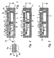
- eine erste Bauform des erfindungsgemäßen Piezoventils in einer Ausgestaltung als 3/3-Wegeventil in schematischer Längsschnittdarstellung, wobei die Fig. 1 eine Sperrstellung, die Fig. 2 eine Speisestellung und die Fig. 3 eine Entlüftungsstellung wiedergibt,
- Fig. 4 bis 6
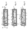
- wiederum ein 3/3-Wege-Piezoventil in einer Längsschnittdarstellung mit im Vergleich zu Fig. 1 bis 3 vertauschten Zuström- und Abströmöffnungen, wobei die Fig. 4 eine Sperrstellung, die Fig. 5 eine Speisestellung und die Fig. 6 eine Entlüftungsstellung wiedergibt,
- Fig. 7 und 8
- das Piezoventil in einer 3/2-Wege-Ausführung und vom Typ "Normalerweise Geschlossen", wobei die Fig. 7 eine Entlüftungsstellung und die Fig. 8 eine Speisestellung wiedergibt,
- Fig. 9 und 10
- wiederum ein 3/2-Wege-Piezoventil im Längsschnitt, allerdings vom Typ "Normalerweise Offen", wobei die Fig. 9 eine Speisestellung und die Fig. 10 eine Entlüftungsstellung wiedergibt,
- Fig. 11
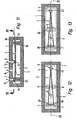
- eine im Vergleich zur Bauform der Fig. 4 bis 6 hinsichtlich der gehäuseseitigen Lagerung des Biegewandlers modifizierte Bauform eines 3/3-Piezoventils im Längsschnitt in Entlüftungsstellung, wobei überdies die Zuströmöffnung und die Abströmöffnung jeweils in Gestalt zweier Einzelöffnungen ausgeführt sind,
- Fig. 12
- einen Schnitt durch das Piezoventil aus Fig. 11 gemäß Schnittlinie XII-XII, wobei durch ein eingezeichnetes Dreieck die Auflagepunkte für den Biegewandler markiert sind,
- Fig. 13
- eine hinsichtlich der Gestaltung der Zuström- und Abströmöffnungen modifizierte Bauform des Piezoventils aus Fig. 11 in einer der Fig. 12 entsprechenden Schnittdarstellung,
- Fig. 14
- das in Fig. 11 in einer Entlüftungsstellung gezeigte Piezoventil, nunmehr unter Einnahme einer Speisestellung,
- Fig. 15
- das Piezoventil aus Fig. 14 im Schnitt gemäß Schnittlinie XV-XV,
- Fig. 16
- eine im Sinne der Fig. 13 modifizierte Bauform des Piezoventils in einer vergleichbaren Schnittdarstellung, wobei die in einer Speisestellung erfolgende Abstützung des Biegewandlers ersichtlich ist,
- Fig. 17
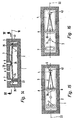
- ein im Vergleich zu Fig. 11 bis 16 hinsichtlich der Lagerung modifiziertes 3/3-Piezoventil, wobei anstelle einer Punktlagerung eine Linienlagerung vorgesehen ist, bei Einnahme einer Entlüftungsstellung,
- Fig. 18
- das Piezoventil aus Fig. 17 im Schnitt gemäß Schnittlinie XVIII-XVIII, wobei durch ein Dreieck die sich ergebende Abstützung für den Biegewandler illustriert ist,
- Fig. 19
- das Piezoventil der Fig. 17 in einer Speisestellung und
- Fig. 20
- das Piezoventil aus Fig. 19 im Schnitt gemäß Schnittlinie XX-XX, wobei wiederum die Abstützung des Biegewandlers durch eine Dreieckslinie verdeutlicht ist.
- Fig. 1 to 3
- a first design of the piezoelectric valve according to the invention in a configuration as a 3/3-way valve in a schematic longitudinal section, wherein FIG. 1 shows a blocking position, FIG. 2 shows a feed position and FIG. 3 shows a venting position,
- Fig. 4 until 6
- again a 3/3-way piezo valve in a longitudinal sectional view with in comparison to FIGS. 1 to 3 exchanged inflow and outflow openings, wherein FIG. 4 shows a blocking position, FIG. 5 shows a feed position and FIG. 6 shows a venting position, FIG.
- FIGS. 7 and 8
- the piezo valve in a 3/2-way design and the type "normally closed", wherein FIG. 7 shows a venting position and FIG. 8 shows a feed position,
- FIGS. 9 and 10
- again a 3/2-way piezo valve in longitudinal section, but of the type "normally open", wherein FIG. 9 shows a feed position and FIG. 10 shows a venting position,
- Fig. 11
- a modified in comparison with the design of Figures 4 to 6 with respect to the housing side mounting of the bending transducer design of a 3/3-piezovalve in venting position, wherein also the inflow opening and the outflow opening are each in the form of two individual openings,
- Fig. 12
- 11 shows a section through the piezo valve from FIG. 11 according to section line XII-XII, wherein the support points for the bending transducer are marked by a drawn in triangle,
- Fig. 13
- 1 with respect to the design of the inflow and outflow openings modified design of the piezoelectric valve from FIG. 11 in a sectional view corresponding to FIG. 12, FIG.
- Fig. 14
- 11 in a venting position shown piezo valve, now taking a dining position,
- Fig. 15
- the piezoelectric valve of FIG. 14 in section according to section line XV-XV,
- Fig. 16
- a modified design of the piezoelectric valve in a similar sectional view in the sense of FIG. 13, wherein the support of the bending transducer taking place in a feed position can be seen,
- Fig. 17
- a 3/3-piezovalve modified in comparison to FIGS. 11 to 16, wherein a linear bearing is provided instead of a point bearing, assuming a venting position,
- Fig. 18
- 17 in section according to section line XVIII-XVIII, wherein by a triangle the resulting support for the bending transducer is illustrated,
- Fig. 19
- the piezo valve of Fig. 17 in a feed position and
- Fig. 20
- 19 in section according to section line XX-XX, wherein again the support of the bending transducer is illustrated by a triangular line.
Die aus der Zeichnung ersichtlichen Piezoventile verfügen jeweils über ein in der Regel zweiteiliges Ventilgehäuse 1, das im Innern eine längliche Ventilkammer 2 begrenzt. In dieser Ventilkammer 2 befindet sich ein Längsgestalt aufweisender, streifenförmiger Biegewandler 3, dessen rückwärtiger Endabschnitt einen Lagerungsabschnitt 4 bildet, mit dem er direkt oder über zwischengeschaltete Lagermittel am Ventilgehäuse 1 gelagert ist. Die Lagerstelle ist mit Bezugsziffer 5 bezeichnet.Each of the piezo valves shown in the drawing has a generally two-
Ausgehend von der Lagerstelle 5 kragt der Biegewandler 3 zum entgegengesetzten Ende hin aus. An den Lagerungsabschnitt 4 schließt sich ein frei endender Arbeitsabschnitt 6 an, der sich über zwei durch ihn steuerbare Ventilöffnungen in Gestalt einer Zuströmöffnung 7 und einer Abströmöffnung 8 hinweg erstreckt.Starting from the
Die vorgenannten steuerbaren Ventilöffnungen sind die zur Ventilkammer 2 hin offenen Mündungen zweier Ventilkanäle in Gestalt eines Zuströmkanals 12 und eines Abströmkanals 13. Der Zuströmkanal 12 ist im Betrieb des Piezoventils mit einer das zu steuernde Fluid liefernden Druckquelle P verbunden. Der Abströmkanal 13 führt, je nachdem, ob das Piezoventil mit einem hydraulischen Medium oder mit Druckluft betrieben wird, zu einem Tank oder zur Atmosphäre R.
Zusätzlich mündet noch ein als Arbeitskanal 14 fungierender weiterer Ventilkanal mit einer Arbeitsöffnung 9 ebenfalls in die Ventilkammer 2 ein. Er wird normalerweise mit einem anzusteuernden Verbraucher verbunden, beispielsweise einem durch Fluidkraft betätigbaren Antrieb.The above-mentioned controllable valve openings are open to the
In addition, another working as a working
Die Biegewandler 3 haben vorzugsweise (vgl. vergrößerter Ausschnitt in Fig. 1) einen trimorphen Aufbau mit zwei unter Zwischenschaltung einer Innenelektrode 15 längsseits aneinander befestigten länglichen Piezokörpern 16a, 16b. Jeder Piezokörper 16a, 16b ist an der der Innenelektrode 15 entgegengesetzten Außenseite mit einer Außenelektrode 17a, 17b versehen. Über aus dem Ventilgehäuse 1 herausgeführte, nur schematisch angedeutete elektrische Kontaktmittel 18 kann an die Elektroden 15, 17a, 17b in ausgewählter Weise eine Ansteuerspannung angelegt werden, die aufgrund des umgekehrten piezoelektrischen Effektes in dem Arbeitsabschnitt 6 eine Auslenkkraft FA hervorruft, die danach strebt, den Arbeitsabschnitt 6 in einer Auslenkebene 22 relativ zu dem sich am Ventilgehäuse 1 abstützenden Lagerungsabschnitt 4 auszulenken. Wenigstens bei den 3/3-Wege-Piezoventilen kann die Ansteuerspannung wahlweise so angelegt werden, dass die Auslenkkraft FA in wahlweise einer von zwei einander entgegengesetzten Richtungen orientiert ist. Hierzu wird beispielsweise entweder zwischen die Innenelektrode 15 und die eine Außenelektrode 17a oder zwischen die Innenelektrode 15 und die andere Außenelektrode 17b eine Ansteuerspannung angelegt. Die Auslenkebene 22 verläuft in Fig. 1 bis 11 sowie 14, 17 und 19 parallel zur Zeichenebene und steht rechtwinkelig auf der Ausdehnungsebene des wie erwähnt streifenförmig ausgebildeten Biegewandlers 3.The bending
Prinzipiell könnte der Biegewandler 3 auch über einen anderen strukturellen Aufbau verfügen und beispielsweise als bimorpher Piezobieger konzipiert sein. Möglich ist ferner eine mehrschichtige Ausführung der Piezokörper 16a, 16b, um einen Multilayer-Biegewandler zu erhalten.In principle, the bending
Bei allen Ausführungsbeispielen erstreckt sich der Biegewandler 3 über sowohl die Zuströmöffnung 7 als auch die Abströmöffnung 8 hinweg, wobei diese beiden Ventilöffnungen auf ein und derselben Längsseite des Arbeitsabschnittes 6 angeordnet sind, bezüglich der sich der Arbeitsabschnitt 6 bei der Auslenkbewegung annähern oder entfernen kann. Mit anderen Worten handelt es sich um eine solche Längsseite des Biegewandlers 3, die einer der beiden großflächigen Biegewandler-Außenflächen zugeordnet ist. Dabei sind die beiden steuerbaren Ventilöffnungen 7, 8 in der Längsrichtung des Arbeitsabschnittes 6 mit Abstand zueinander angeordnet, sodass entweder - wie im Falle der Bauformen gemäß Fig. 1 bis 3 und 7 bis 10 - die Zuströmöffnung 7 zwischen dem Lagerungsabschnitt 4 und der Abströmöffnung 8 liegt, oder - wie bei den Bauformen der Fig. 4 bis 6 und 11 bis 20 - die Abströmöffnung 8 zwischen dem Lagerungsabschnitt 4 und der Zuströmöffnung 7 platziert ist. Die mögliche Auslenkbewegung des Arbeitsabschnittes 6 ist in der Zeichnung allgemein durch den Doppelpfeil 23 angedeutet. In Richtung dieser Auslenkbewegung 23 gegenüberliegend einer jeweiligen steuerbaren Ventilöffnungen 7, 8, verfügt der Arbeitsabschnitt 6 des Biegewandlers 3 über jeweils einen Steuerabschnitt, der - entsprechend der Zuordnung zur entsprechenden Ventilöffnung 7, 8 - als zuströmseitiger Steuerabschnitt 24 bzw. als abströmseitiger Steuerabschnitt 25 bezeichnet sei. Diese Steuerabschnitte 24, 25 können unmittelbar von einer der Biegewandlerschichten gebildet sein oder aber - wie dies bei den Ausführungsbeispielen der Fall ist - von jeweils einem aus geeignetem Dichtmaterial bestehenden, am Biegewandler 3 fixierten Pad. Beispielsweise handelt es sich bei den Pads um Gummi-Pads.In all exemplary embodiments, the bending
Die beiden steuerbaren Ventilöffnungen 7, 8 sind jeweils von einem bezüglich benachbarter Ventilgehäuseflächen erhabenen ventilsitz 26 umrahmt. Allerdings ist die erhabene Ventilsitzgestaltung nicht zwingend.The two
Jeder Steuerabschnitt 24, 25 ist in der Lage, den ihm gegenüberliegenden Ventilkanal 12, 13 fluiddicht abzusperren, wenn er mit einer gewissen Anpresskraft an den zugeordneten Ventilsitz 26 angedrückt wird.Each
Mithin ist es möglich, die Fluidströmung durch den Zuströmkanal 12 und den Abströmkanal 13 zu steuern, indem der zugeordnete Steuerabschnitt 24, 25 entweder am betreffenden Ventilsitz 26 anliegt oder von diesem abgehoben wird, sodass die betroffene Zuströmöffnung 7 oder Abströmöffnung 8 entweder freigegeben oder verschlossen ist. Die entsprechende Position der Steuerabschnitte 24, 25 wird durch die Aktivierung und Nichtaktivierung und die daraus resultierende Auslenkung und Nichtauslenkung des Biegewandlers 3 hervorgerufen.Consequently, it is possible to control the fluid flow through the
Die Arbeitsöffnung 9 ist unabhängig von der momentanen Stellung des Arbeitsabschnittes 6 offen, sodass eine ständige Verbindung zwischen dem Arbeitskanal 14 und der Ventilkammer 2 vorliegt. Zweckmäßigerweise befindet sich die Arbeitsöffnung 9 auf der gleichen Längsseite des Biegewandlers 3 wie die beiden steuerbaren Ventilöffnungen 7, 8. Zu Gunsten kurzer Strömungswege ist sie dabei zweckmäßigerweise zwischen den beiden steuerbaren Ventilöffnungen 7, 8 platziert.The working
Jedes Piezoventil verfügt über zusätzlich zum Biegewandler 3 vorgesehene Beaufschlagungsmittel 27, die im Bereich des zuströmseitigen Steuerabschnittes 24 an dem Arbeitsabschnitt 6 angreifen, und durch die der zuströmseitige Steuerabschnitt 24 ständig in Richtung seiner Schließstellung beaufschlagt ist. Bevorzugt handelt es sich bei den Beaufschlagungsmitteln um eine zwischen dem Arbeitsabschnitt 6 und dem Ventilgehäuse 1 wirksame Federeinrichtung und dabei insbesondere um mindestens eine sich einenends an der Innenfläche der Ventilkammer 2 und andernends rückseitig am Arbeitsabschnitt 6 abstützende mechanische Druckfeder.Each piezo valve has in addition to the bending
Alternativ könnten auch andere Beaufschlagungsmittel vorgesehen sein, beispielsweise solche auf fluidischem oder magnetischem Wirkprinzip. Jedenfalls sollte die Beaufschlagungskraft so groß sein, dass der im Zuströmkanal anstehende Fluiddruck nicht in der Lage ist, den in der Schließstellung befindlichen zuströmseitigen Steuerabschnitt 24 abzuheben. Insbesondere sollte die Beaufschlagungskraft mindestens so hoch sein, dass der zuströmseitige Steuerabschnitt 24 in der Schließstellung gehalten werden kann, wenn sich der abströmseitige Steuerabschnitt in der vom zugeordneten Ventilsitz abgehobenen Freigabestellung befindet.Alternatively, other loading means could be provided, for example, those on fluidic or magnetic action principle. In any case, the application force should be so great that the pending in the inflow channel fluid pressure is not able to lift the located in the closed position
Das in Fig. 1 bis 3 gezeigte Piezoventil ist als 3/3-Wegeventil konzipiert, verfügt also über drei Schaltstellungen zur Verknüpfung der drei Ventilöffnungen 7, 8, 9. Sein Biegewandler 3 weist im elektrisch spannungslosen Neutralzustand eine zumindest im Wesentlichen lineare Erstreckung auf und ist in der Ventilkammer 2 so angeordnet, dass beide Steuerabschnitte 24, 25 am gegenüberliegenden Ventilsitz 26 anliegen und die Schließstellung einnehmen. Die Längsachse 28 des Biegewandlers 3 verläuft dabei mit Abstand etwa parallel zu einer die beiden Ventilsitze 26 enthaltenden Ventilsitzebene 32. In dieser Ventilsitzebene 32 liegt auch die Lagerstelle 5, sodass der Biegewandler 3 in seiner Längsrichtung an drei Stellen gehäusefest abgestützt ist. Aufgrund der Beaufschlagungsmittel 27, die in der Längsrichtung des Biegewandlers 3 auf gleicher Höhe mit der Zuströmöffnung 7 auf den Biegewandler 3 einwirken, wird die Zuströmöffnung 7 durch den zuströmseitigen Steuerabschnitt 24 mit einer ausreichend hohen Anpresskraft verschlossen, um ein Abheben durch den anstehenden Fluiddruck zu verhindern.The piezoelectric valve shown in Fig. 1 to 3 is designed as a 3/3-way valve, so has three switching positions for linking the three
Somit liegt eine Sperrstellung vor, in der der Biegewandler 3 beide steuerbaren Ventilöffnungen 7, 8 dicht verschließt. Um zum Erhalt dieser Sperrstellung die beiden Steuerabschnitte 24, 25 exakt ausrichten zu können, ist beim Ausführungsbeispiel die Lagerstelle 5 in der Auslenkebene 22 gemäß Doppelpfeil 33 quer zur Längsrichtung des Biegewandlers 3 justierbar. Es lässt sich damit also die Ausrichtung des Biegewandlers 3 in Bezug auf die Ventilsitzebene 32 exakt einstellen, um in der Sperrstellung die Schließstellung der beiden Steuerabschnitte 24, 25 zu gewährleisten.Thus, there is a blocking position in which the bending
Um bei dem Piezoventil der Fig. 1 bis 3 die Speisestellung zu erhalten, in der die Zuströmöffnung 7 über die Ventilkammer 2 hinweg mit der Arbeitsöffnung 9 in Verbindung steht und gleichzeitig die Abströmöffnung 8 verschlossen bleibt, wird der Biegewandler 3 so angesteuert, dass sich eine Auslenkkraft FA in Richtung der die Ventilsitze 26 aufweisenden Längsseite einstellt. Dies bewirkt ein Auslenken des Arbeitsabschnittes 6 im Sinne eines Ausbauchens im mittleren Bereich, wobei der zuströmseitige Steuerabschnitt 24 von der Zuströmöffnung 7 unter Überwindung der Anpresskraft der Beaufschlagungsmittel 27 abgehoben wird (Fig. 2).In order to obtain the feed position in the piezo valve of FIGS. 1 to 3, in which the
Soll hingegen die Entlüftungsstellung eingestellt werden, in der die Abströmöffnung 8 über die Ventilkammer 2 mit der Arbeitsöffnung 9 verbunden und gleichzeitig die Zuströmöffnung 7 verschlossen ist, erfolgt eine Ansteuerung des Biegewandlers 3 in entgegengesetzter Richtung, sodass sich eine von der Seite der Ventilsitze 26 wegweisende Auslenkkraft FA einstellt. Gemäß Fig. 3 führt dies dazu, dass der dem freien Ende des Arbeitsabschnittes 6 zugeordnete abströmseitige Steuerabschnitt 25 von der Abströmöffnung 8 wegschwenkt und abhebt, während der zuströmseitige Steuerabschnitt 24 durch die Beaufschlagungsmittel 27 gegen die Zuströmöffnung 7 gedrückt wird.If, on the other hand, the venting position is to be set, in which the
Abgesehen von der vertauschten Anordnung der beiden steuerbaren Ventilöffnungen 7, 8 und einer anderen Lagerungsart des Lagerungsabschnittes 4 stimmt der Aufbau des in Fig. 4 bis 6 gezeigten Piezoventils mit dem vorstehend beschriebenen überein. Zum Erhalt der Speisestellung wird hier im Arbeitsabschnitt 6 eine von der Seite der Ventilsitze 26 wegweisende Auslenkkraft FA hervorgerufen, die dazu führt, dass der Arbeitsabschnitt 6 im Bereich des mit dem zuströmseitigen Steuerabschnitt 24 versehenen freien Endes unter Zurückdrängung der Beaufschlagungsmittel 27 von der Zuströmöffnung 7 weggeschwenkt wird, während gleichzeitig der abströmseitige Steuerabschnitt 25 aufgrund der Durchbiegung des Biegewandlers 3 am Ventilsitz 26 der Abströmöffnung 8 anliegen bleibt. Zum Erhalt der Entlüftungsstellung erfolgt eine umgekehrte Ansteuerung des Biegewandlers 3, wobei nun der zuströmseitige Steuerabschnitt 24 zusätzlich zu den Beaufschlagungsmitteln 27 auch noch mit der sich ergebenden Auslenkkraft FA an die Zuströmöffnung 7 angedrückt wird, während sich der Arbeitsabschnitt 6 gleichzeitig so ausbaucht, dass der im mittleren Bereich liegende abströmseitige Steuerabschnitt 25 von der Abströmöffnung 8 abhebt.Apart from the reversed arrangement of the two
Die in Fig. 7 bis 10 gezeigten Piezoventile verfügen über eine 3/2-Funktionalität und können bei Bedarf mit einem Biegewandler betrieben werden, dessen Arbeitsabschnitt 6 in lediglich einer Richtung eine Auslenkkraft FA ausüben kann. Im grundsätzlichen Aufbau unterscheiden sich die Piezoventile der Fig. 7 bis 10 von demjenigen der Fig. 1 bis 3 ansonsten nur dadurch, dass die Lagerstelle 5 in der Richtung der Auslenkbewegung 23 anders positioniert ist, sodass der Biegewandler 3 im elektrisch spannungslosen Neutralzustand gegenüber der Ventilsitzebene 32 schräg angestellt ist. Dadurch wird erreicht, dass in dem Neutralzustand der eine Steuerabschnitt die Schließstellung und der andere Steuerabschnitt die Freigabestellung einnimmt.The piezo valves shown in FIGS. 7 to 10 have a 3/2 functionality and, if required, can be operated with a bending transducer whose working
Bei der Anordnung gemäß Fig. 7 und 8 ist die Neigung des Biegewandlers 3 im Neutralzustand so gewählt, dass der zuströmseitige Steuerabschnitt die Zuströmöffnung 7 verschließt, während der abströmseitige Steuerabschnitt 25 von der Abströmöffnung 8 abgehoben ist und diese freigibt. Es handelt sich somit um ein Ventil des Typs "Normalerweise Geschlossen", wobei im elektrisch spannungslosen Neutralzustand die Entlüftungsstellung gegeben ist. Zum Umschalten in die Speisestellung wird der Biegewandler 3 so erregt, dass der Arbeitsabschnitt eine Auslenkkraft FA in Richtung zu den Ventilsitzen 26 erfährt, sodass er sich im mittleren Bereich ausbaucht und letztlich der in Fig. 8 gezeigte Zustand erhalten wird, der mit dem anhand der Fig. 2 beschriebenen vergleichbar ist.In the arrangement according to FIGS. 7 and 8, the inclination of the bending
Das Piezoventil der Fig. 9 und 10 ist vom Typ "Normalerweise Offen", wobei im Neutralzustand die Speisestellung vorliegt. Die Neigung des Biegewandlers 3 gegenüber der Ventilsitzebene 32 ist hier verglichen mit dem Neutralzustand der Fig. 7 entgegengesetzt, sodass der abströmseitige Steuerabschnitt 25 an der Abströmöffnung 8 anliegt, während der zuströmseitige Steuerabschnitt 24 von der Zuströmöffnung 7 abgehoben ist.The piezo valve of FIGS. 9 and 10 is of the "normally open" type, with the feed position in the neutral state. The inclination of the bending
Um hier die Entlüftungsstellung zu erreichen, wird der Biegewandler so angesteuert, dass der Arbeitsabschnitt eine von der Seite der Ventilsitze 26 wegweisende Auslenkkraft FA erfährt, was zu dem in Fig. 10 gezeigten Zustand führt, der mit demjenigen der Fig. 3 vergleichbar ist.In order to achieve the venting position here, the bending transducer is controlled such that the working section experiences a deflecting force F A pointing away from the side of the valve seats 26, which leads to the state shown in FIG. 10, which is comparable to that of FIG.
Ist die Lagerstelle 5 in der Auslenkebene justierbar, wie dies bei den Piezoventilen der Fig. 1 bis 3 und 7 bis 10 der Fall ist (Justierbewegung 33), kann allein durch die höhenmäßige Justierung der Lagerstelle 5 die gewünschte Ventilfunktionalität bzw. der gewünschte Ventiltyp vorgegeben werden. Entsprechend der gewählten Einstellung ergibt sich im Neutralzustand des Biegewandlers 3 eine unterschiedliche Relativlage zur Ventilsitzebene 32 - entweder im Wesentlichen parallel oder in die eine oder andere Richtung geneigt -, sodass auf der Grundlage eines Basisventils eine äußerst flexible Ventilherstellung unter Verwendung gleicher Komponenten möglich ist.If the
Es wäre prinzipiell möglich, den Biegewandler 3 an seinem Lagerungsabschnitt 4 mit Bezug zum Ventilgehäuse 1 unbeweglich zu fixieren, beispielsweise durch eine feste Einspannung oder durch eine Einbettung in einer nicht verformbaren Vergussmasse. Allerdings werden die gewünschten Verformungen des Biegewandlers 3 bei den Schaltvorgängen begünstigt, wenn der Biegewandler 3 an der Lagerstelle 5 insgesamt bezüglich des Ventilgehäuses 1 verschwenkbar gelagert ist, also einschließlich des Lagerungsabschnittes 4. Dies trifft auf alle Ausführungsbeispiele zu.It would in principle be possible to immovably fix the bending
Als besonders vorteilhaft hat sich hierbei die bei den Ausführungsbeispielen der Fig. 1 bis 3 und 7 bis 20 gezeigte Art der Schwenklagerung erwiesen. Hier ist der Lagerungsabschnitt 4 zwischen sich am Ventilgehäuse 1 abstützenden Federmitteln 34 und einem ventilgehäusefesten Widerlager in einer in gewissem Rahmen nachgiebigen Weise eingespannt. Die federelastische Vorspannung bewirkt, dass der Lagerungsabschnitt 4 relativ zu dem ortsfesten Widerlager 35 verschwenken kann, wobei entsprechend der momentanen Auslenkung eine mehr oder weniger starke Kompression der Federmittel 34 stattfindet, die den Schwenkwinkel kompensiert.In this case, the type of pivotal mounting shown in the exemplary embodiments of FIGS. 1 to 3 and 7 to 20 has proven to be particularly advantageous. Here, the
Bei den Ausführungsbeispielen der Fig. 1 bis 3 und 7 bis 10 ist diese Art der Lagerung in vorteilhafter Weise mit der schon angesprochenen höhenmäßigen Justiermöglichkeit für die Lagerstelle 5 verknüpft. Dies geschieht dadurch, dass das Widerlager 35 an einem relativ zum Ventilgehäuse 1 in Richtung der gewünschten Justierbewegung 33 variabel positionierbaren Stellglied 36 angeordnet ist, beispielsweise eine Schraube. Durch Verstellen des Stellgliedes 36 ändert sich die Position des Widerlagers 35 in der Richtung der Auslenkbewegung 23, wobei der Lagerungsabschnitt 4 mitgenommen wird und in jeder eingestellten Position durch die ihn beaufschlagenden Federmittel 34 trotzdem sicher fixiert bleibt. In Abhängigkeit von der Positionierung des Stellgliedes 36 verändert sich lediglich der Kompressionsgrad der Federmittel 34, was sich jedoch auf die Qualität der Schwenklagerung nicht auswirkt.In the embodiments of Figs. 1 to 3 and 7 to 10, this type of storage is linked in an advantageous manner with the previously mentioned height adjustment for the
Im Gegensatz dazu ist bei den Ausführungsbeispielen der Fig. 11 bis 20 das Widerlager 35 ortsfest am Ventilgehäuse 1 angeordnet. Damit verbunden ist eine einfachere und kostengünstigere Herstellung.In contrast, in the embodiments of FIGS. 11 to 20, the
Bei dem Ausführungsbeispiel der Fig. 4 bis 6 ist der Biegewandler 3 an der Lagerstelle 5 über zur Auslenkebene 22 rechtwinkelige, ortsfeste Drehachsmittel 37 verschwenkbar gelagert. Diese Drehachsmittel 37 sind unmittelbar als materielle Drehachse realisiert, beispielsweise durch an den beiden längsseitigen Rändern des Biegewandlers 3 vorstehende Achszapfen oder eine den Biegewandler 3 durchsetzende, beidseits vorstehende Welle, wobei die vorstehenden Abschnitte jeweils am Ventilgehäuse unter Gewährleistung des gewünschten Drehfreiheitsgrades gelagert sind.In the embodiment of FIGS. 4 to 6, the bending
Es ist unter allen Umständen zweckmäßig, den Biegewandler 3 innerhalb des Ventilgehäuses 1 in den möglichen Schaltstellungen so gegenüber dem Ventilgehäuse 1 abzustützen, dass er bezüglich seiner Längsachse 38 über eine statisch definierte Mehrpunktauflage, insbesondere eine Dreipunktauflage, verfügt. Dies gewährleistet eine sichere, vollumfängliche Anlage der Steuerabschnitte 24, 25 am zugeordneten Ventilsitz 26 bei Einnahme der jeweiligen Schließstellung.It is expedient under all circumstances to support the bending
Beim Ausführungsbeispiel der Fig. 17 bis 20 wird dies in Verbindung mit steuerbaren Ventilöffnungen 7, 8, die jeweils aus einer einzigen Öffnung bestehen, durch ein Widerlager 35 erreicht, das einen zur Auslenkebene 22 rechtwinkeligen, linienförmigen Widerlagerabschnitt 42 definiert. Um einen solchen linienförmigen Widerlagerabschnitt 42 zu erhalten, kann das Widerlager 35 höckerähnlich mit scharfer Kante ausgebildet sein.In the embodiment of FIGS. 17 to 20 this is achieved in conjunction with
In sowohl der Speisestellung gemäß Fig. 19 und 20 als auch der Entlüftungsstellung gemäß Fig. 17 und 18 liegt der Biegewandler 3 zum einen mit einem seiner Steuerabschnitte punktuell auf einem der Ventilsitze 26 auf, während er zum anderen an dem Widerlager 35 linienförmig abgestützt ist. Daraus resultiert die in Fig. 18 und 20 durch ein Dreieck verdeutlichte Abstützkonfiguration, wobei die Spitze des Dreieckes jeweils im Bereich desjenigen Steuerabschnittes liegt, der sich an einem Ventilsitz 26 abstützt.In both the feed position according to FIGS. 19 and 20 and the venting position according to FIGS. 17 and 18, the bending
Eine vergleichbar statisch definierte Dreipunktauflage für den Biegewandler 3 kann allerdings auch in Verbindung mit einem Widerlager 35 erzielt werden, das gemäß Fig. 11 bis 16 einen punktuellen Widerlagerabschnitt 43 definiert, an dem sich der Lagerungsabschnitt 4 des Biegewandlers 3 abstützt. In diesem Falle wird zum Erhalt der dreieckförmigen Abstützkonfiguration dafür gesorgt, dass die beiden Steuerabschnitte 24, 25 in der Schließstellung rechtwinkelig zur Auslenkebene 22 über eine größere Länge oder an mehreren beabstandeten Punkten gegenüber dem Ventilgehäuse 1 abgestützt werden.However, a comparatively statically defined three-point support for the bending
Dies ist beispielsweise gemäß der Bauform der Fig. 13 und 16 dadurch realisierbar, dass die jeweils zu steuernde Ventilöffnung 7, 8 einen Öffnungsquerschnitt besitzt, der in bezüglich der Auslenkebene 22 rechtwinkeliger Richtung eine längliche Gestalt aufweist, sodass auch der die betreffende Ventilöffnung 7, 8 umrahmende Ventilsitz 26 eine entsprechende Längsgestalt hat.This can be realized, for example, in accordance with the design of FIGS. 13 and 16 in that the
Alternativ könnte auch gemäß den Bauformen der Fig. 12 und 15 die jeweilige steuerbare Ventilöffnung 7, 8 nicht nur aus einer einzigen Öffnung, sondern aus mehreren und insbesondere aus zwei rechtwinkelig zu der Auslenkebene 22 nebeneinander angeordneten Einzelöffnungen bestehen. In diesem Fall besitzt jede Einzelöffnung ihren eigenen Ventilsitz 26, wobei durch die quer zur Auslenkebene 22 beabstandete Anordnung der Ventilsitze 26 wiederum eine Abstützung für den Biegewandler 3 erreicht wird, die diesen an einem Verkippen bzw. Verdrehen um die Längsachse hindert.Alternatively, according to the constructions of FIGS. 12 and 15, the respective
Beide Ausführungsvarianten haben noch den weiteren Vorteil, dass sich mit ihnen größere Öffnungsquerschnitte verwirklichen lassen, ohne die Öffnungsabmessungen in der Längsrichtung des Biegewandlers 3 vergrößern zu müssen.Both embodiments have the further advantage that can be realized with them larger opening cross-sections without having to increase the opening dimensions in the longitudinal direction of the bending
Claims (18)
- Piezoelectric valve, with a bending transducer (3) located in a valve casing (1), having at one end a mounting section (4) mounted on the casing side, and with a freely ending operating section (6) which extends into a valve chamber (2) via two controllable valve ports in the form of an inflow port (7) and an outflow port (8), and may be deflected by means of suitable electrical activation into a deflection plane (22) at right-angles to its longitudinal direction in order to open each of the two controllable valve ports (7, 8) alternately to connect with an operating port (9), or to close them through contact with an assigned valve seat (26), characterised in that the two controllable valve ports (7, 8) are located on the same long side of the operating section (6), spaced apart in its longitudinal direction, wherein the operating section (6) has two correspondingly spaced apart inflow-side and outflow-side control sections (24, 25) assigned to the two controllable valve ports (7, 8), and that pressure-loading means (27) provided in addition to the bending transducer (3) act on the operating section (6) in the area of the inflow-side control section (24), pressing the inflow-side control section (24) constantly towards its closed position, wherein the pressurising force is high enough to keep the inflow-side control section (24) in the closed position when the outflow-side control section (25) is in the open position.
- Piezoelectric valve according to claim 1, characterised in that the inflow port (7) is located between the mounting section (4) and the outflow port (8).
- Piezoelectric valve according to claim 1, characterised in that the outflow port (8) is located between the mounting section (4) and the inflow port (7).
- Piezoelectric valve according to any of claims 1 to 3, characterised in that the bending transducer (3) is so designed and arranged that, in the electrically dead neutral state, both control sections (24, 25) adopt the closed position relative to their respectively assigned controllable valve port (7, 8), while the bending transducer (3) may be so electrically activated that its operating section (6), starting from the neutral state, undergoes a deflection force alternately in one or the other direction.
- Piezoelectric valve according to claim 4, characterised in that in the neutral state the bending transducer (3) has an extent which is at least substantially linear, wherein its longitudinal axis (28) is aligned substantially parallel to one of the valve seats (26) of the valve seat plane (32) containing the two controllable valve ports (7, 8).
- Piezoelectric valve according to any of claims 1 to 3, characterised in that the bending transducer (3) is so designed and arranged that, in the electrically dead neutral state, one control section adopts the closed position and the other control section adopts the open position.
- Piezoelectric valve according to claim 6, characterised in that in the neutral state the bending transducer (3) has an extent which is at least substantially linear, wherein its longitudinal axis (28) is inclined relative to one of the valve seats (26) of the valve seat plane (32) containing the two controllable valve ports (7, 8).
- Piezoelectric valve according to any of claims 1 to 7, characterised in that the bearing point (5) for the mounting section (4) of the bending transducer (3) is adjustable in the deflection plane (22) at right-angles to the longitudinal direction of the bending transducer (3).
- Piezoelectric valve according to claim 8 in combination with claim 7 characterised in that, by suitable adjustment of the bearing point (5), the inclined position of the bending transducer (3) in the neutral state may be so adjusted alternately that one or the other control section adopts the closed position and the other respective control section adopts the open position.
- Piezoelectric valve according to any of claims 1 to 9, characterised in that the pressure-loading means (27) are formed by a spring device acting between the operating section (6) and the valve casing (1).
- Piezoelectric valve according to any of claims 1 to 10, characterised in that the operating port (9) is located on the same long side of the bending transducer (3) as the controllable valve ports (7, 8).
- Piezoelectric valve according to any of claims 1 to 11, characterised in that the bending transducer (3) is pivotably mounted at the bearing point (5), relative to the valve casing (1).
- Piezoelectric valve according to claim 12, characterised in that the bending transducer (3) is pivotably mounted at the bearing point (5) via stationary rotary axis means (37) at right-angles to the deflection plane (22).
- Piezoelectric valve according to claim 12 characterised in that, at the bearing point (5), the mounting section (4) is pressed resiliently by spring means (34) supported on the valve casing (1) against an abutment (35) secured to the valve casing.
- Piezoelectric valve according to claim 14, characterised in that the abutment (35) is adjustable relative to the valve casing (1).
- Piezoelectric valve according to claim 14 or 15, characterised in that the abutment (35) defines an abutment section (42, 43) which is punctiform or linear at right-angles to the deflection plane and with which the mounting section (4) of the bending transducer (3) makes contact.
- Piezoelectric valve according to any of claims 1 to 16, characterised in that at least one of the two controllable valve ports (7, 8) has a port cross-section of oblong shape at right-angles to the deflection plane (22).
- Piezoelectric valve according to any of claims 1 to 17, characterised in that at least one of the two controllable valve ports (7, 8) has several individual ports adjacent to one another at right-angles to the deflection plane (22).
Priority Applications (5)
| Application Number | Priority Date | Filing Date | Title |
|---|---|---|---|
| DE200450000445 DE502004000445D1 (en) | 2004-02-11 | 2004-02-11 | piezo valve |
| DK04002968T DK1564464T3 (en) | 2004-02-11 | 2004-02-11 | piezo valve |
| EP20040002968 EP1564464B1 (en) | 2004-02-11 | 2004-02-11 | Piezo valve |
| AT04002968T ATE323861T1 (en) | 2004-02-11 | 2004-02-11 | PIEZO VALVE |
| US11/052,524 US7322376B2 (en) | 2004-02-11 | 2005-02-07 | Piezoelectric valve |
Applications Claiming Priority (1)
| Application Number | Priority Date | Filing Date | Title |
|---|---|---|---|
| EP20040002968 EP1564464B1 (en) | 2004-02-11 | 2004-02-11 | Piezo valve |
Publications (2)
| Publication Number | Publication Date |
|---|---|
| EP1564464A1 EP1564464A1 (en) | 2005-08-17 |
| EP1564464B1 true EP1564464B1 (en) | 2006-04-19 |
Family
ID=34684658
Family Applications (1)
| Application Number | Title | Priority Date | Filing Date |
|---|---|---|---|
| EP20040002968 Expired - Lifetime EP1564464B1 (en) | 2004-02-11 | 2004-02-11 | Piezo valve |
Country Status (5)
| Country | Link |
|---|---|
| US (1) | US7322376B2 (en) |
| EP (1) | EP1564464B1 (en) |
| AT (1) | ATE323861T1 (en) |
| DE (1) | DE502004000445D1 (en) |
| DK (1) | DK1564464T3 (en) |
Cited By (1)
| Publication number | Priority date | Publication date | Assignee | Title |
|---|---|---|---|---|
| WO2013079083A1 (en) | 2011-12-02 | 2013-06-06 | Festo Ag & Co. Kg | Valve arrangement |
Families Citing this family (28)
| Publication number | Priority date | Publication date | Assignee | Title |
|---|---|---|---|---|
| CA2613853A1 (en) * | 2006-12-11 | 2008-06-11 | Fisher & Paykel Appliances Limited | Variable flow valve |
| DE102007038545A1 (en) * | 2007-08-16 | 2009-02-19 | Robert Bosch Gmbh | Programmable filter processor |
| US8220533B2 (en) * | 2008-07-17 | 2012-07-17 | Schlumberger Technology Corporation | Downhole piezoelectric devices |
| US8978757B2 (en) | 2008-07-17 | 2015-03-17 | Schlumberger Technology Corporation | Remote actuation testing tool for high pressure differential downhole environments |
| US8082952B2 (en) * | 2008-08-22 | 2011-12-27 | Hamilton Sundstrand Corporation | Piezoelectric bending element actuator for servo valve |
| US8414366B2 (en) * | 2008-10-20 | 2013-04-09 | GM Global Technology Operations LLC | Active material enabled pressure release valves and methods of use |
| TWI435196B (en) | 2009-10-15 | 2014-04-21 | Pivotal Systems Corp | Method and apparatus for gas flow control |
| US9400004B2 (en) | 2010-11-29 | 2016-07-26 | Pivotal Systems Corporation | Transient measurements of mass flow controllers |
| US8631825B2 (en) * | 2010-12-22 | 2014-01-21 | Inzi Controls Co., Ltd. | Piezo valve |
| EP2518378B1 (en) * | 2011-04-28 | 2013-12-25 | Inzi Controls Co., Ltd. | Piezo valve |
| KR101990172B1 (en) * | 2012-08-16 | 2019-06-17 | 페스토 악티엔 게젤샤프트 운트 코. 카게 | Fluid valve |
| KR101386671B1 (en) * | 2012-11-29 | 2014-04-21 | 인지컨트롤스 주식회사 | Piezo valve and manufacturing method therefor |
| DE102012023532A1 (en) * | 2012-11-30 | 2014-06-05 | Wabco Gmbh | Electropneumatic valve |
| WO2014201032A1 (en) * | 2013-06-11 | 2014-12-18 | Illinois Tool Works Inc. | High flow piezo type valve |
| US10401202B2 (en) | 2015-07-10 | 2019-09-03 | Pivotal Systems Corporation | Method and apparatus for gas flow control |
| NL2019572A (en) | 2016-10-20 | 2018-04-24 | Asml Netherlands Bv | A pressure control valve, a fluid handling structure for lithographic apparatus and a lithographic apparatus |
| DE102017200308B4 (en) * | 2017-01-10 | 2021-07-08 | Fraunhofer-Gesellschaft zur Förderung der angewandten Forschung e.V. | Micromechanical components with mechanical actuators |
| DE102017204662C5 (en) * | 2017-03-21 | 2021-02-25 | Conti Temic Microelectronic Gmbh | Pneumatic valve |
| WO2019215672A1 (en) | 2018-05-11 | 2019-11-14 | Matthews International Corporation | Systems and methods for controlling operation of micro-valves for use in jetting assemblies |
| US11794476B2 (en) | 2018-05-11 | 2023-10-24 | Matthews International Corporation | Micro-valves for use in jetting assemblies |
| MX2020012076A (en) | 2018-05-11 | 2021-03-25 | Matthews Int Corp | Electrode structures for micro-valves for use in jetting assemblies. |
| CN112368149B (en) | 2018-05-11 | 2023-01-13 | 马修斯国际公司 | System and method for sealing a microvalve used in a jetting assembly |
| US11639057B2 (en) | 2018-05-11 | 2023-05-02 | Matthews International Corporation | Methods of fabricating micro-valves and jetting assemblies including such micro-valves |
| CN112081971B (en) * | 2020-08-17 | 2022-05-20 | 费尔顿技术(上海)有限公司 | Piezoelectric gas flow control valve |
| CN112066005B (en) * | 2020-08-17 | 2022-06-24 | 费尔顿技术(上海)有限公司 | Piezoelectric pilot valve |
| TWM617111U (en) * | 2021-06-22 | 2021-09-11 | 科際精密股份有限公司 | Actuator device |
| CN216407869U (en) * | 2021-06-22 | 2022-04-29 | 科际精密股份有限公司 | Air pressure adjusting device |
| DE102022125517A1 (en) | 2022-10-04 | 2024-04-04 | Aventics Gmbh | Systems and methods for piezoelectric valves |
Family Cites Families (13)
| Publication number | Priority date | Publication date | Assignee | Title |
|---|---|---|---|---|
| US4474212A (en) * | 1981-05-11 | 1984-10-02 | Harper-Wyman Company | Proportional flow control valve |
| US4492360A (en) * | 1982-06-07 | 1985-01-08 | The Lee Company | Piezoelectric valve |
| US4450375A (en) * | 1982-11-12 | 1984-05-22 | Kiwi Coders Corporation | Piezoelectric fluid control device |
| US4629926A (en) * | 1985-10-21 | 1986-12-16 | Kiwi Coders Corporation | Mounting for piezoelectric bender of fluid control device |
| CH681168A5 (en) * | 1989-11-10 | 1993-01-29 | Westonbridge Int Ltd | Micro-pump for medicinal dosing |
| AT396392B (en) * | 1991-09-30 | 1993-08-25 | Hoerbiger Fluidtechnik Gmbh | PIEZO VALVE |
| DE4320909C1 (en) * | 1993-06-18 | 1994-06-01 | Siemens Ag | Servo valve operating between inlet and outlet air nozzles - uses flexible beam held at one end in adjustable braked liner |
| DE19648730C2 (en) * | 1996-11-25 | 1998-11-19 | Fraunhofer Ges Forschung | Piezo-electrically operated micro valve |
| US6193029B1 (en) | 1997-07-08 | 2001-02-27 | Active Control Experts, Inc. | Damper and valve |
| DE19854620C2 (en) * | 1998-11-26 | 2001-05-17 | Festo Ag & Co | Valve device, in particular amplifier |
| ATE284490T1 (en) * | 2000-05-25 | 2004-12-15 | Festo Ag & Co | VALVE DEVICE |
| DK1207329T3 (en) * | 2000-11-20 | 2003-04-22 | Festo Ag & Co | piezo valve |
| DE10311238A1 (en) * | 2003-03-14 | 2004-10-07 | Festo Ag & Co. | Method of manufacturing a valve |
-
2004
- 2004-02-11 DK DK04002968T patent/DK1564464T3/en active
- 2004-02-11 DE DE200450000445 patent/DE502004000445D1/en not_active Expired - Lifetime
- 2004-02-11 AT AT04002968T patent/ATE323861T1/en active
- 2004-02-11 EP EP20040002968 patent/EP1564464B1/en not_active Expired - Lifetime
-
2005
- 2005-02-07 US US11/052,524 patent/US7322376B2/en not_active Expired - Fee Related
Cited By (3)
| Publication number | Priority date | Publication date | Assignee | Title |
|---|---|---|---|---|
| WO2013079083A1 (en) | 2011-12-02 | 2013-06-06 | Festo Ag & Co. Kg | Valve arrangement |
| CN103946612A (en) * | 2011-12-02 | 2014-07-23 | 费斯托股份有限两合公司 | Valve arrangement |
| CN103946612B (en) * | 2011-12-02 | 2016-02-24 | 费斯托股份有限两合公司 | Valve assembly |
Also Published As
| Publication number | Publication date |
|---|---|
| EP1564464A1 (en) | 2005-08-17 |
| US20050199301A1 (en) | 2005-09-15 |
| DK1564464T3 (en) | 2006-05-29 |
| ATE323861T1 (en) | 2006-05-15 |
| DE502004000445D1 (en) | 2006-05-24 |
| US7322376B2 (en) | 2008-01-29 |
Similar Documents
| Publication | Publication Date | Title |
|---|---|---|
| EP1564464B1 (en) | Piezo valve | |
| EP1207329B1 (en) | Piezo valve | |
| DE69916264T2 (en) | ELECTRICALLY ADJUSTABLE VALVE | |
| EP1758007B1 (en) | Fluid actuated position controller | |
| EP1133651B1 (en) | Pivoting valve device, especially an amplifier | |
| DE3608550A1 (en) | Piezoelectrically actuated valve | |
| EP1158182A1 (en) | Valve arrangement | |
| EP2275729B1 (en) | Valve | |
| EP1026407A1 (en) | Fluid control element | |
| EP2017511B1 (en) | Piezo-electric valve | |
| DE102014108678A1 (en) | spool valve | |
| EP3414482B1 (en) | Proportional valve | |
| EP3443231B1 (en) | Electropneumatic valve assembly | |
| EP0361183B1 (en) | Switch valve with ceramic valve elements | |
| EP2193298B1 (en) | Valve | |
| AT412366B (en) | VALVE | |
| DE102010035263B4 (en) | piezo valve | |
| DE102008056751A1 (en) | Fluidic device i.e. bidirectional peristaltic micropump, for delivering medicament, has spring elements bearing force from side of inlet opening, and membrane section pressed against pusher by force for movement into pre-stressed position | |
| DE102017130199B4 (en) | Film transducer, valve, pump and method of operating a pump | |
| EP2846070B1 (en) | Solenoid valve | |
| EP1970608B1 (en) | Choke valve | |
| EP0145859B1 (en) | Valve device with a piezoelectric or magnetostrictive actuating member | |
| EP1078167A1 (en) | Microvalve | |
| DE102015113164A1 (en) | Fluidic control | |
| DE102020103476B4 (en) | valve drive and valve |
Legal Events
| Date | Code | Title | Description |
|---|---|---|---|
| PUAI | Public reference made under article 153(3) epc to a published international application that has entered the european phase |
Free format text: ORIGINAL CODE: 0009012 |
|
| 17P | Request for examination filed |
Effective date: 20040907 |
|
| AK | Designated contracting states |
Kind code of ref document: A1 Designated state(s): AT BE BG CH CY CZ DE DK EE ES FI FR GB GR HU IE IT LI LU MC NL PT RO SE SI SK TR |
|
| AX | Request for extension of the european patent |
Extension state: AL LT LV MK |
|
| GRAP | Despatch of communication of intention to grant a patent |
Free format text: ORIGINAL CODE: EPIDOSNIGR1 |
|
| GRAS | Grant fee paid |
Free format text: ORIGINAL CODE: EPIDOSNIGR3 |
|
| GRAA | (expected) grant |
Free format text: ORIGINAL CODE: 0009210 |
|
| AK | Designated contracting states |
Kind code of ref document: B1 Designated state(s): AT BE BG CH CY CZ DE DK EE ES FI FR GB GR HU IE IT LI LU MC NL PT RO SE SI SK TR |
|
| PG25 | Lapsed in a contracting state [announced via postgrant information from national office to epo] |
Ref country code: CZ Free format text: LAPSE BECAUSE OF FAILURE TO SUBMIT A TRANSLATION OF THE DESCRIPTION OR TO PAY THE FEE WITHIN THE PRESCRIBED TIME-LIMIT Effective date: 20060419 Ref country code: IT Free format text: LAPSE BECAUSE OF FAILURE TO SUBMIT A TRANSLATION OF THE DESCRIPTION OR TO PAY THE FEE WITHIN THE PRESCRIBED TIME-LIMIT;WARNING: LAPSES OF ITALIAN PATENTS WITH EFFECTIVE DATE BEFORE 2007 MAY HAVE OCCURRED AT ANY TIME BEFORE 2007. THE CORRECT EFFECTIVE DATE MAY BE DIFFERENT FROM THE ONE RECORDED. Effective date: 20060419 Ref country code: RO Free format text: LAPSE BECAUSE OF FAILURE TO SUBMIT A TRANSLATION OF THE DESCRIPTION OR TO PAY THE FEE WITHIN THE PRESCRIBED TIME-LIMIT Effective date: 20060419 Ref country code: SK Free format text: LAPSE BECAUSE OF FAILURE TO SUBMIT A TRANSLATION OF THE DESCRIPTION OR TO PAY THE FEE WITHIN THE PRESCRIBED TIME-LIMIT Effective date: 20060419 Ref country code: SI Free format text: LAPSE BECAUSE OF FAILURE TO SUBMIT A TRANSLATION OF THE DESCRIPTION OR TO PAY THE FEE WITHIN THE PRESCRIBED TIME-LIMIT Effective date: 20060419 Ref country code: FI Free format text: LAPSE BECAUSE OF FAILURE TO SUBMIT A TRANSLATION OF THE DESCRIPTION OR TO PAY THE FEE WITHIN THE PRESCRIBED TIME-LIMIT Effective date: 20060419 Ref country code: IE Free format text: LAPSE BECAUSE OF FAILURE TO SUBMIT A TRANSLATION OF THE DESCRIPTION OR TO PAY THE FEE WITHIN THE PRESCRIBED TIME-LIMIT Effective date: 20060419 |
|
| REG | Reference to a national code |
Ref country code: GB Ref legal event code: FG4D Free format text: NOT ENGLISH |
|
| REG | Reference to a national code |
Ref country code: CH Ref legal event code: NV Representative=s name: TROESCH SCHEIDEGGER WERNER AG |
|
| AKX | Designation fees paid |
Designated state(s): AT BE BG CH CY CZ DE DK EE ES FI FR GB GR HU IE IT LI LU MC NL PT RO SE SI SK TR |
|
| GBT | Gb: translation of ep patent filed (gb section 77(6)(a)/1977) |
Effective date: 20060419 |
|
| REF | Corresponds to: |
Ref document number: 502004000445 Country of ref document: DE Date of ref document: 20060524 Kind code of ref document: P |
|
| REG | Reference to a national code |
Ref country code: IE Ref legal event code: FG4D Free format text: LANGUAGE OF EP DOCUMENT: GERMAN |
|
| PG25 | Lapsed in a contracting state [announced via postgrant information from national office to epo] |
Ref country code: SE Free format text: LAPSE BECAUSE OF FAILURE TO SUBMIT A TRANSLATION OF THE DESCRIPTION OR TO PAY THE FEE WITHIN THE PRESCRIBED TIME-LIMIT Effective date: 20060719 |
|
| PG25 | Lapsed in a contracting state [announced via postgrant information from national office to epo] |
Ref country code: ES Free format text: LAPSE BECAUSE OF FAILURE TO SUBMIT A TRANSLATION OF THE DESCRIPTION OR TO PAY THE FEE WITHIN THE PRESCRIBED TIME-LIMIT Effective date: 20060730 |
|
| PG25 | Lapsed in a contracting state [announced via postgrant information from national office to epo] |
Ref country code: PT Free format text: LAPSE BECAUSE OF FAILURE TO SUBMIT A TRANSLATION OF THE DESCRIPTION OR TO PAY THE FEE WITHIN THE PRESCRIBED TIME-LIMIT Effective date: 20060919 |
|
| REG | Reference to a national code |
Ref country code: IE Ref legal event code: FD4D |
|
| ET | Fr: translation filed | ||
| PG25 | Lapsed in a contracting state [announced via postgrant information from national office to epo] |
Ref country code: MC Free format text: LAPSE BECAUSE OF NON-PAYMENT OF DUE FEES Effective date: 20070228 |
|
| PLBE | No opposition filed within time limit |
Free format text: ORIGINAL CODE: 0009261 |
|
| STAA | Information on the status of an ep patent application or granted ep patent |
Free format text: STATUS: NO OPPOSITION FILED WITHIN TIME LIMIT |
|
| 26N | No opposition filed |
Effective date: 20070122 |
|
| BERE | Be: lapsed |
Owner name: FESTO A.G. & CO Effective date: 20070228 |
|
| PG25 | Lapsed in a contracting state [announced via postgrant information from national office to epo] |
Ref country code: BE Free format text: LAPSE BECAUSE OF NON-PAYMENT OF DUE FEES Effective date: 20070228 |
|
| PG25 | Lapsed in a contracting state [announced via postgrant information from national office to epo] |
Ref country code: GR Free format text: LAPSE BECAUSE OF FAILURE TO SUBMIT A TRANSLATION OF THE DESCRIPTION OR TO PAY THE FEE WITHIN THE PRESCRIBED TIME-LIMIT Effective date: 20060720 |
|
| PG25 | Lapsed in a contracting state [announced via postgrant information from national office to epo] |
Ref country code: BG Free format text: LAPSE BECAUSE OF FAILURE TO SUBMIT A TRANSLATION OF THE DESCRIPTION OR TO PAY THE FEE WITHIN THE PRESCRIBED TIME-LIMIT Effective date: 20060719 |
|
| PG25 | Lapsed in a contracting state [announced via postgrant information from national office to epo] |
Ref country code: EE Free format text: LAPSE BECAUSE OF FAILURE TO SUBMIT A TRANSLATION OF THE DESCRIPTION OR TO PAY THE FEE WITHIN THE PRESCRIBED TIME-LIMIT Effective date: 20060419 |
|
| PGFP | Annual fee paid to national office [announced via postgrant information from national office to epo] |
Ref country code: DK Payment date: 20090213 Year of fee payment: 6 |
|
| PGFP | Annual fee paid to national office [announced via postgrant information from national office to epo] |
Ref country code: NL Payment date: 20090224 Year of fee payment: 6 |
|
| PG25 | Lapsed in a contracting state [announced via postgrant information from national office to epo] |
Ref country code: LU Free format text: LAPSE BECAUSE OF NON-PAYMENT OF DUE FEES Effective date: 20070211 Ref country code: CY Free format text: LAPSE BECAUSE OF FAILURE TO SUBMIT A TRANSLATION OF THE DESCRIPTION OR TO PAY THE FEE WITHIN THE PRESCRIBED TIME-LIMIT Effective date: 20060419 |
|
| PG25 | Lapsed in a contracting state [announced via postgrant information from national office to epo] |
Ref country code: TR Free format text: LAPSE BECAUSE OF FAILURE TO SUBMIT A TRANSLATION OF THE DESCRIPTION OR TO PAY THE FEE WITHIN THE PRESCRIBED TIME-LIMIT Effective date: 20060419 Ref country code: HU Free format text: LAPSE BECAUSE OF FAILURE TO SUBMIT A TRANSLATION OF THE DESCRIPTION OR TO PAY THE FEE WITHIN THE PRESCRIBED TIME-LIMIT Effective date: 20061020 |
|
| REG | Reference to a national code |
Ref country code: NL Ref legal event code: V1 Effective date: 20100901 |
|
| REG | Reference to a national code |
Ref country code: DK Ref legal event code: EBP |
|
| PG25 | Lapsed in a contracting state [announced via postgrant information from national office to epo] |
Ref country code: DK Free format text: LAPSE BECAUSE OF NON-PAYMENT OF DUE FEES Effective date: 20100228 Ref country code: NL Free format text: LAPSE BECAUSE OF NON-PAYMENT OF DUE FEES Effective date: 20100901 |
|
| PGFP | Annual fee paid to national office [announced via postgrant information from national office to epo] |
Ref country code: IT Payment date: 20150223 Year of fee payment: 12 |
|
| PGFP | Annual fee paid to national office [announced via postgrant information from national office to epo] |
Ref country code: GB Payment date: 20150122 Year of fee payment: 12 |
|
| REG | Reference to a national code |
Ref country code: FR Ref legal event code: PLFP Year of fee payment: 13 |
|
| PGFP | Annual fee paid to national office [announced via postgrant information from national office to epo] |
Ref country code: CH Payment date: 20160222 Year of fee payment: 13 |
|
| PGFP | Annual fee paid to national office [announced via postgrant information from national office to epo] |
Ref country code: FR Payment date: 20160222 Year of fee payment: 13 |
|
| GBPC | Gb: european patent ceased through non-payment of renewal fee |
Effective date: 20160211 |
|
| PG25 | Lapsed in a contracting state [announced via postgrant information from national office to epo] |
Ref country code: IT Free format text: LAPSE BECAUSE OF NON-PAYMENT OF DUE FEES Effective date: 20160211 |
|
| PG25 | Lapsed in a contracting state [announced via postgrant information from national office to epo] |
Ref country code: GB Free format text: LAPSE BECAUSE OF NON-PAYMENT OF DUE FEES Effective date: 20160211 |
|
| PGFP | Annual fee paid to national office [announced via postgrant information from national office to epo] |
Ref country code: AT Payment date: 20170217 Year of fee payment: 14 |
|
| REG | Reference to a national code |
Ref country code: CH Ref legal event code: PL |
|
| PG25 | Lapsed in a contracting state [announced via postgrant information from national office to epo] |
Ref country code: LI Free format text: LAPSE BECAUSE OF NON-PAYMENT OF DUE FEES Effective date: 20170228 Ref country code: CH Free format text: LAPSE BECAUSE OF NON-PAYMENT OF DUE FEES Effective date: 20170228 |
|
| REG | Reference to a national code |
Ref country code: FR Ref legal event code: ST Effective date: 20171031 |
|
| PG25 | Lapsed in a contracting state [announced via postgrant information from national office to epo] |
Ref country code: FR Free format text: LAPSE BECAUSE OF NON-PAYMENT OF DUE FEES Effective date: 20170228 |
|
| REG | Reference to a national code |
Ref country code: AT Ref legal event code: MM01 Ref document number: 323861 Country of ref document: AT Kind code of ref document: T Effective date: 20180211 |
|
| PG25 | Lapsed in a contracting state [announced via postgrant information from national office to epo] |
Ref country code: AT Free format text: LAPSE BECAUSE OF NON-PAYMENT OF DUE FEES Effective date: 20180211 |
|
| REG | Reference to a national code |
Ref country code: DE Ref legal event code: R082 Ref document number: 502004000445 Country of ref document: DE Representative=s name: PATENTANWAELTE MAGENBAUER & KOLLEGEN PARTNERSC, DE Ref country code: DE Ref legal event code: R081 Ref document number: 502004000445 Country of ref document: DE Owner name: FESTO SE & CO. KG, DE Free format text: FORMER OWNER: FESTO AG & CO. KG, 73734 ESSLINGEN, DE Ref country code: DE Ref legal event code: R081 Ref document number: 502004000445 Country of ref document: DE Owner name: FESTO AG & CO. KG, DE Free format text: FORMER OWNER: FESTO AG & CO. KG, 73734 ESSLINGEN, DE |
|
| PGFP | Annual fee paid to national office [announced via postgrant information from national office to epo] |
Ref country code: DE Payment date: 20220609 Year of fee payment: 20 |
|
| REG | Reference to a national code |
Ref country code: DE Ref legal event code: R071 Ref document number: 502004000445 Country of ref document: DE |