EP1563808A1 - Intervertebral disc nucleus implants - Google Patents
Intervertebral disc nucleus implants Download PDFInfo
- Publication number
- EP1563808A1 EP1563808A1 EP05010361A EP05010361A EP1563808A1 EP 1563808 A1 EP1563808 A1 EP 1563808A1 EP 05010361 A EP05010361 A EP 05010361A EP 05010361 A EP05010361 A EP 05010361A EP 1563808 A1 EP1563808 A1 EP 1563808A1
- Authority
- EP
- European Patent Office
- Prior art keywords
- implant
- elastic body
- intervertebral disc
- configuration
- lumen
- Prior art date
- Legal status (The legal status is an assumption and is not a legal conclusion. Google has not performed a legal analysis and makes no representation as to the accuracy of the status listed.)
- Granted
Links
Images


Classifications
-
- A—HUMAN NECESSITIES
- A61—MEDICAL OR VETERINARY SCIENCE; HYGIENE
- A61F—FILTERS IMPLANTABLE INTO BLOOD VESSELS; PROSTHESES; DEVICES PROVIDING PATENCY TO, OR PREVENTING COLLAPSING OF, TUBULAR STRUCTURES OF THE BODY, e.g. STENTS; ORTHOPAEDIC, NURSING OR CONTRACEPTIVE DEVICES; FOMENTATION; TREATMENT OR PROTECTION OF EYES OR EARS; BANDAGES, DRESSINGS OR ABSORBENT PADS; FIRST-AID KITS
- A61F2/00—Filters implantable into blood vessels; Prostheses, i.e. artificial substitutes or replacements for parts of the body; Appliances for connecting them with the body; Devices providing patency to, or preventing collapsing of, tubular structures of the body, e.g. stents
- A61F2/02—Prostheses implantable into the body
- A61F2/30—Joints
- A61F2/44—Joints for the spine, e.g. vertebrae, spinal discs
- A61F2/441—Joints for the spine, e.g. vertebrae, spinal discs made of inflatable pockets or chambers filled with fluid, e.g. with hydrogel
-
- A—HUMAN NECESSITIES
- A61—MEDICAL OR VETERINARY SCIENCE; HYGIENE
- A61F—FILTERS IMPLANTABLE INTO BLOOD VESSELS; PROSTHESES; DEVICES PROVIDING PATENCY TO, OR PREVENTING COLLAPSING OF, TUBULAR STRUCTURES OF THE BODY, e.g. STENTS; ORTHOPAEDIC, NURSING OR CONTRACEPTIVE DEVICES; FOMENTATION; TREATMENT OR PROTECTION OF EYES OR EARS; BANDAGES, DRESSINGS OR ABSORBENT PADS; FIRST-AID KITS
- A61F2/00—Filters implantable into blood vessels; Prostheses, i.e. artificial substitutes or replacements for parts of the body; Appliances for connecting them with the body; Devices providing patency to, or preventing collapsing of, tubular structures of the body, e.g. stents
- A61F2/02—Prostheses implantable into the body
- A61F2/30—Joints
- A61F2/44—Joints for the spine, e.g. vertebrae, spinal discs
- A61F2/442—Intervertebral or spinal discs, e.g. resilient
-
- A—HUMAN NECESSITIES
- A61—MEDICAL OR VETERINARY SCIENCE; HYGIENE
- A61F—FILTERS IMPLANTABLE INTO BLOOD VESSELS; PROSTHESES; DEVICES PROVIDING PATENCY TO, OR PREVENTING COLLAPSING OF, TUBULAR STRUCTURES OF THE BODY, e.g. STENTS; ORTHOPAEDIC, NURSING OR CONTRACEPTIVE DEVICES; FOMENTATION; TREATMENT OR PROTECTION OF EYES OR EARS; BANDAGES, DRESSINGS OR ABSORBENT PADS; FIRST-AID KITS
- A61F2/00—Filters implantable into blood vessels; Prostheses, i.e. artificial substitutes or replacements for parts of the body; Appliances for connecting them with the body; Devices providing patency to, or preventing collapsing of, tubular structures of the body, e.g. stents
- A61F2/02—Prostheses implantable into the body
- A61F2/30—Joints
- A61F2/46—Special tools or methods for implanting or extracting artificial joints, accessories, bone grafts or substitutes, or particular adaptations therefor
- A61F2/4603—Special tools or methods for implanting or extracting artificial joints, accessories, bone grafts or substitutes, or particular adaptations therefor for insertion or extraction of endoprosthetic joints or of accessories thereof
- A61F2/4611—Special tools or methods for implanting or extracting artificial joints, accessories, bone grafts or substitutes, or particular adaptations therefor for insertion or extraction of endoprosthetic joints or of accessories thereof of spinal prostheses
-
- A—HUMAN NECESSITIES
- A61—MEDICAL OR VETERINARY SCIENCE; HYGIENE
- A61B—DIAGNOSIS; SURGERY; IDENTIFICATION
- A61B17/00—Surgical instruments, devices or methods, e.g. tourniquets
- A61B17/02—Surgical instruments, devices or methods, e.g. tourniquets for holding wounds open; Tractors
- A61B17/025—Joint distractors
- A61B2017/0256—Joint distractors for the spine
-
- A—HUMAN NECESSITIES
- A61—MEDICAL OR VETERINARY SCIENCE; HYGIENE
- A61F—FILTERS IMPLANTABLE INTO BLOOD VESSELS; PROSTHESES; DEVICES PROVIDING PATENCY TO, OR PREVENTING COLLAPSING OF, TUBULAR STRUCTURES OF THE BODY, e.g. STENTS; ORTHOPAEDIC, NURSING OR CONTRACEPTIVE DEVICES; FOMENTATION; TREATMENT OR PROTECTION OF EYES OR EARS; BANDAGES, DRESSINGS OR ABSORBENT PADS; FIRST-AID KITS
- A61F2/00—Filters implantable into blood vessels; Prostheses, i.e. artificial substitutes or replacements for parts of the body; Appliances for connecting them with the body; Devices providing patency to, or preventing collapsing of, tubular structures of the body, e.g. stents
- A61F2/02—Prostheses implantable into the body
- A61F2/30—Joints
- A61F2/3094—Designing or manufacturing processes
- A61F2/30965—Reinforcing the prosthesis by embedding particles or fibres during moulding or dipping
-
- A—HUMAN NECESSITIES
- A61—MEDICAL OR VETERINARY SCIENCE; HYGIENE
- A61F—FILTERS IMPLANTABLE INTO BLOOD VESSELS; PROSTHESES; DEVICES PROVIDING PATENCY TO, OR PREVENTING COLLAPSING OF, TUBULAR STRUCTURES OF THE BODY, e.g. STENTS; ORTHOPAEDIC, NURSING OR CONTRACEPTIVE DEVICES; FOMENTATION; TREATMENT OR PROTECTION OF EYES OR EARS; BANDAGES, DRESSINGS OR ABSORBENT PADS; FIRST-AID KITS
- A61F2/00—Filters implantable into blood vessels; Prostheses, i.e. artificial substitutes or replacements for parts of the body; Appliances for connecting them with the body; Devices providing patency to, or preventing collapsing of, tubular structures of the body, e.g. stents
- A61F2/02—Prostheses implantable into the body
- A61F2/28—Bones
- A61F2002/2817—Bone stimulation by chemical reactions or by osteogenic or biological products for enhancing ossification, e.g. by bone morphogenetic or morphogenic proteins [BMP] or by transforming growth factors [TGF]
-
- A—HUMAN NECESSITIES
- A61—MEDICAL OR VETERINARY SCIENCE; HYGIENE
- A61F—FILTERS IMPLANTABLE INTO BLOOD VESSELS; PROSTHESES; DEVICES PROVIDING PATENCY TO, OR PREVENTING COLLAPSING OF, TUBULAR STRUCTURES OF THE BODY, e.g. STENTS; ORTHOPAEDIC, NURSING OR CONTRACEPTIVE DEVICES; FOMENTATION; TREATMENT OR PROTECTION OF EYES OR EARS; BANDAGES, DRESSINGS OR ABSORBENT PADS; FIRST-AID KITS
- A61F2/00—Filters implantable into blood vessels; Prostheses, i.e. artificial substitutes or replacements for parts of the body; Appliances for connecting them with the body; Devices providing patency to, or preventing collapsing of, tubular structures of the body, e.g. stents
- A61F2/02—Prostheses implantable into the body
- A61F2/30—Joints
- A61F2002/30001—Additional features of subject-matter classified in A61F2/28, A61F2/30 and subgroups thereof
- A61F2002/30003—Material related properties of the prosthesis or of a coating on the prosthesis
- A61F2002/3006—Properties of materials and coating materials
- A61F2002/30062—(bio)absorbable, biodegradable, bioerodable, (bio)resorbable, resorptive
-
- A—HUMAN NECESSITIES
- A61—MEDICAL OR VETERINARY SCIENCE; HYGIENE
- A61F—FILTERS IMPLANTABLE INTO BLOOD VESSELS; PROSTHESES; DEVICES PROVIDING PATENCY TO, OR PREVENTING COLLAPSING OF, TUBULAR STRUCTURES OF THE BODY, e.g. STENTS; ORTHOPAEDIC, NURSING OR CONTRACEPTIVE DEVICES; FOMENTATION; TREATMENT OR PROTECTION OF EYES OR EARS; BANDAGES, DRESSINGS OR ABSORBENT PADS; FIRST-AID KITS
- A61F2/00—Filters implantable into blood vessels; Prostheses, i.e. artificial substitutes or replacements for parts of the body; Appliances for connecting them with the body; Devices providing patency to, or preventing collapsing of, tubular structures of the body, e.g. stents
- A61F2/02—Prostheses implantable into the body
- A61F2/30—Joints
- A61F2002/30001—Additional features of subject-matter classified in A61F2/28, A61F2/30 and subgroups thereof
- A61F2002/30003—Material related properties of the prosthesis or of a coating on the prosthesis
- A61F2002/3006—Properties of materials and coating materials
- A61F2002/30092—Properties of materials and coating materials using shape memory or superelastic materials, e.g. nitinol
-
- A—HUMAN NECESSITIES
- A61—MEDICAL OR VETERINARY SCIENCE; HYGIENE
- A61F—FILTERS IMPLANTABLE INTO BLOOD VESSELS; PROSTHESES; DEVICES PROVIDING PATENCY TO, OR PREVENTING COLLAPSING OF, TUBULAR STRUCTURES OF THE BODY, e.g. STENTS; ORTHOPAEDIC, NURSING OR CONTRACEPTIVE DEVICES; FOMENTATION; TREATMENT OR PROTECTION OF EYES OR EARS; BANDAGES, DRESSINGS OR ABSORBENT PADS; FIRST-AID KITS
- A61F2/00—Filters implantable into blood vessels; Prostheses, i.e. artificial substitutes or replacements for parts of the body; Appliances for connecting them with the body; Devices providing patency to, or preventing collapsing of, tubular structures of the body, e.g. stents
- A61F2/02—Prostheses implantable into the body
- A61F2/30—Joints
- A61F2002/30001—Additional features of subject-matter classified in A61F2/28, A61F2/30 and subgroups thereof
- A61F2002/30108—Shapes
- A61F2002/3011—Cross-sections or two-dimensional shapes
- A61F2002/30112—Rounded shapes, e.g. with rounded corners
- A61F2002/30133—Rounded shapes, e.g. with rounded corners kidney-shaped or bean-shaped
-
- A—HUMAN NECESSITIES
- A61—MEDICAL OR VETERINARY SCIENCE; HYGIENE
- A61F—FILTERS IMPLANTABLE INTO BLOOD VESSELS; PROSTHESES; DEVICES PROVIDING PATENCY TO, OR PREVENTING COLLAPSING OF, TUBULAR STRUCTURES OF THE BODY, e.g. STENTS; ORTHOPAEDIC, NURSING OR CONTRACEPTIVE DEVICES; FOMENTATION; TREATMENT OR PROTECTION OF EYES OR EARS; BANDAGES, DRESSINGS OR ABSORBENT PADS; FIRST-AID KITS
- A61F2/00—Filters implantable into blood vessels; Prostheses, i.e. artificial substitutes or replacements for parts of the body; Appliances for connecting them with the body; Devices providing patency to, or preventing collapsing of, tubular structures of the body, e.g. stents
- A61F2/02—Prostheses implantable into the body
- A61F2/30—Joints
- A61F2002/30001—Additional features of subject-matter classified in A61F2/28, A61F2/30 and subgroups thereof
- A61F2002/30108—Shapes
- A61F2002/3011—Cross-sections or two-dimensional shapes
- A61F2002/30159—Concave polygonal shapes
- A61F2002/30179—X-shaped
-
- A—HUMAN NECESSITIES
- A61—MEDICAL OR VETERINARY SCIENCE; HYGIENE
- A61F—FILTERS IMPLANTABLE INTO BLOOD VESSELS; PROSTHESES; DEVICES PROVIDING PATENCY TO, OR PREVENTING COLLAPSING OF, TUBULAR STRUCTURES OF THE BODY, e.g. STENTS; ORTHOPAEDIC, NURSING OR CONTRACEPTIVE DEVICES; FOMENTATION; TREATMENT OR PROTECTION OF EYES OR EARS; BANDAGES, DRESSINGS OR ABSORBENT PADS; FIRST-AID KITS
- A61F2/00—Filters implantable into blood vessels; Prostheses, i.e. artificial substitutes or replacements for parts of the body; Appliances for connecting them with the body; Devices providing patency to, or preventing collapsing of, tubular structures of the body, e.g. stents
- A61F2/02—Prostheses implantable into the body
- A61F2/30—Joints
- A61F2002/30001—Additional features of subject-matter classified in A61F2/28, A61F2/30 and subgroups thereof
- A61F2002/30108—Shapes
- A61F2002/30199—Three-dimensional shapes
- A61F2002/302—Three-dimensional shapes toroidal, e.g. rings
-
- A—HUMAN NECESSITIES
- A61—MEDICAL OR VETERINARY SCIENCE; HYGIENE
- A61F—FILTERS IMPLANTABLE INTO BLOOD VESSELS; PROSTHESES; DEVICES PROVIDING PATENCY TO, OR PREVENTING COLLAPSING OF, TUBULAR STRUCTURES OF THE BODY, e.g. STENTS; ORTHOPAEDIC, NURSING OR CONTRACEPTIVE DEVICES; FOMENTATION; TREATMENT OR PROTECTION OF EYES OR EARS; BANDAGES, DRESSINGS OR ABSORBENT PADS; FIRST-AID KITS
- A61F2/00—Filters implantable into blood vessels; Prostheses, i.e. artificial substitutes or replacements for parts of the body; Appliances for connecting them with the body; Devices providing patency to, or preventing collapsing of, tubular structures of the body, e.g. stents
- A61F2/02—Prostheses implantable into the body
- A61F2/30—Joints
- A61F2002/30001—Additional features of subject-matter classified in A61F2/28, A61F2/30 and subgroups thereof
- A61F2002/30108—Shapes
- A61F2002/30199—Three-dimensional shapes
- A61F2002/30224—Three-dimensional shapes cylindrical
-
- A—HUMAN NECESSITIES
- A61—MEDICAL OR VETERINARY SCIENCE; HYGIENE
- A61F—FILTERS IMPLANTABLE INTO BLOOD VESSELS; PROSTHESES; DEVICES PROVIDING PATENCY TO, OR PREVENTING COLLAPSING OF, TUBULAR STRUCTURES OF THE BODY, e.g. STENTS; ORTHOPAEDIC, NURSING OR CONTRACEPTIVE DEVICES; FOMENTATION; TREATMENT OR PROTECTION OF EYES OR EARS; BANDAGES, DRESSINGS OR ABSORBENT PADS; FIRST-AID KITS
- A61F2/00—Filters implantable into blood vessels; Prostheses, i.e. artificial substitutes or replacements for parts of the body; Appliances for connecting them with the body; Devices providing patency to, or preventing collapsing of, tubular structures of the body, e.g. stents
- A61F2/02—Prostheses implantable into the body
- A61F2/30—Joints
- A61F2002/30001—Additional features of subject-matter classified in A61F2/28, A61F2/30 and subgroups thereof
- A61F2002/30108—Shapes
- A61F2002/30199—Three-dimensional shapes
- A61F2002/30291—Three-dimensional shapes spirally-coiled, i.e. having a 2D spiral cross-section
-
- A—HUMAN NECESSITIES
- A61—MEDICAL OR VETERINARY SCIENCE; HYGIENE
- A61F—FILTERS IMPLANTABLE INTO BLOOD VESSELS; PROSTHESES; DEVICES PROVIDING PATENCY TO, OR PREVENTING COLLAPSING OF, TUBULAR STRUCTURES OF THE BODY, e.g. STENTS; ORTHOPAEDIC, NURSING OR CONTRACEPTIVE DEVICES; FOMENTATION; TREATMENT OR PROTECTION OF EYES OR EARS; BANDAGES, DRESSINGS OR ABSORBENT PADS; FIRST-AID KITS
- A61F2/00—Filters implantable into blood vessels; Prostheses, i.e. artificial substitutes or replacements for parts of the body; Appliances for connecting them with the body; Devices providing patency to, or preventing collapsing of, tubular structures of the body, e.g. stents
- A61F2/02—Prostheses implantable into the body
- A61F2/30—Joints
- A61F2002/30001—Additional features of subject-matter classified in A61F2/28, A61F2/30 and subgroups thereof
- A61F2002/30316—The prosthesis having different structural features at different locations within the same prosthesis; Connections between prosthetic parts; Special structural features of bone or joint prostheses not otherwise provided for
- A61F2002/30535—Special structural features of bone or joint prostheses not otherwise provided for
- A61F2002/30563—Special structural features of bone or joint prostheses not otherwise provided for having elastic means or damping means, different from springs, e.g. including an elastomeric core or shock absorbers
-
- A—HUMAN NECESSITIES
- A61—MEDICAL OR VETERINARY SCIENCE; HYGIENE
- A61F—FILTERS IMPLANTABLE INTO BLOOD VESSELS; PROSTHESES; DEVICES PROVIDING PATENCY TO, OR PREVENTING COLLAPSING OF, TUBULAR STRUCTURES OF THE BODY, e.g. STENTS; ORTHOPAEDIC, NURSING OR CONTRACEPTIVE DEVICES; FOMENTATION; TREATMENT OR PROTECTION OF EYES OR EARS; BANDAGES, DRESSINGS OR ABSORBENT PADS; FIRST-AID KITS
- A61F2/00—Filters implantable into blood vessels; Prostheses, i.e. artificial substitutes or replacements for parts of the body; Appliances for connecting them with the body; Devices providing patency to, or preventing collapsing of, tubular structures of the body, e.g. stents
- A61F2/02—Prostheses implantable into the body
- A61F2/30—Joints
- A61F2002/30001—Additional features of subject-matter classified in A61F2/28, A61F2/30 and subgroups thereof
- A61F2002/30316—The prosthesis having different structural features at different locations within the same prosthesis; Connections between prosthetic parts; Special structural features of bone or joint prostheses not otherwise provided for
- A61F2002/30535—Special structural features of bone or joint prostheses not otherwise provided for
- A61F2002/30594—Special structural features of bone or joint prostheses not otherwise provided for slotted, e.g. radial or meridian slot ending in a polar aperture, non-polar slots, horizontal or arcuate slots
-
- A—HUMAN NECESSITIES
- A61—MEDICAL OR VETERINARY SCIENCE; HYGIENE
- A61F—FILTERS IMPLANTABLE INTO BLOOD VESSELS; PROSTHESES; DEVICES PROVIDING PATENCY TO, OR PREVENTING COLLAPSING OF, TUBULAR STRUCTURES OF THE BODY, e.g. STENTS; ORTHOPAEDIC, NURSING OR CONTRACEPTIVE DEVICES; FOMENTATION; TREATMENT OR PROTECTION OF EYES OR EARS; BANDAGES, DRESSINGS OR ABSORBENT PADS; FIRST-AID KITS
- A61F2/00—Filters implantable into blood vessels; Prostheses, i.e. artificial substitutes or replacements for parts of the body; Appliances for connecting them with the body; Devices providing patency to, or preventing collapsing of, tubular structures of the body, e.g. stents
- A61F2/02—Prostheses implantable into the body
- A61F2/30—Joints
- A61F2002/30001—Additional features of subject-matter classified in A61F2/28, A61F2/30 and subgroups thereof
- A61F2002/30316—The prosthesis having different structural features at different locations within the same prosthesis; Connections between prosthetic parts; Special structural features of bone or joint prostheses not otherwise provided for
- A61F2002/30535—Special structural features of bone or joint prostheses not otherwise provided for
- A61F2002/30604—Special structural features of bone or joint prostheses not otherwise provided for modular
-
- A—HUMAN NECESSITIES
- A61—MEDICAL OR VETERINARY SCIENCE; HYGIENE
- A61F—FILTERS IMPLANTABLE INTO BLOOD VESSELS; PROSTHESES; DEVICES PROVIDING PATENCY TO, OR PREVENTING COLLAPSING OF, TUBULAR STRUCTURES OF THE BODY, e.g. STENTS; ORTHOPAEDIC, NURSING OR CONTRACEPTIVE DEVICES; FOMENTATION; TREATMENT OR PROTECTION OF EYES OR EARS; BANDAGES, DRESSINGS OR ABSORBENT PADS; FIRST-AID KITS
- A61F2/00—Filters implantable into blood vessels; Prostheses, i.e. artificial substitutes or replacements for parts of the body; Appliances for connecting them with the body; Devices providing patency to, or preventing collapsing of, tubular structures of the body, e.g. stents
- A61F2/02—Prostheses implantable into the body
- A61F2/30—Joints
- A61F2002/30001—Additional features of subject-matter classified in A61F2/28, A61F2/30 and subgroups thereof
- A61F2002/30667—Features concerning an interaction with the environment or a particular use of the prosthesis
- A61F2002/30677—Means for introducing or releasing pharmaceutical products, e.g. antibiotics, into the body
-
- A—HUMAN NECESSITIES
- A61—MEDICAL OR VETERINARY SCIENCE; HYGIENE
- A61F—FILTERS IMPLANTABLE INTO BLOOD VESSELS; PROSTHESES; DEVICES PROVIDING PATENCY TO, OR PREVENTING COLLAPSING OF, TUBULAR STRUCTURES OF THE BODY, e.g. STENTS; ORTHOPAEDIC, NURSING OR CONTRACEPTIVE DEVICES; FOMENTATION; TREATMENT OR PROTECTION OF EYES OR EARS; BANDAGES, DRESSINGS OR ABSORBENT PADS; FIRST-AID KITS
- A61F2/00—Filters implantable into blood vessels; Prostheses, i.e. artificial substitutes or replacements for parts of the body; Appliances for connecting them with the body; Devices providing patency to, or preventing collapsing of, tubular structures of the body, e.g. stents
- A61F2/02—Prostheses implantable into the body
- A61F2/30—Joints
- A61F2/30767—Special external or bone-contacting surface, e.g. coating for improving bone ingrowth
- A61F2/30771—Special external or bone-contacting surface, e.g. coating for improving bone ingrowth applied in original prostheses, e.g. holes or grooves
- A61F2002/30838—Microstructures
-
- A—HUMAN NECESSITIES
- A61—MEDICAL OR VETERINARY SCIENCE; HYGIENE
- A61F—FILTERS IMPLANTABLE INTO BLOOD VESSELS; PROSTHESES; DEVICES PROVIDING PATENCY TO, OR PREVENTING COLLAPSING OF, TUBULAR STRUCTURES OF THE BODY, e.g. STENTS; ORTHOPAEDIC, NURSING OR CONTRACEPTIVE DEVICES; FOMENTATION; TREATMENT OR PROTECTION OF EYES OR EARS; BANDAGES, DRESSINGS OR ABSORBENT PADS; FIRST-AID KITS
- A61F2/00—Filters implantable into blood vessels; Prostheses, i.e. artificial substitutes or replacements for parts of the body; Appliances for connecting them with the body; Devices providing patency to, or preventing collapsing of, tubular structures of the body, e.g. stents
- A61F2/02—Prostheses implantable into the body
- A61F2/30—Joints
- A61F2/30767—Special external or bone-contacting surface, e.g. coating for improving bone ingrowth
- A61F2/30771—Special external or bone-contacting surface, e.g. coating for improving bone ingrowth applied in original prostheses, e.g. holes or grooves
- A61F2002/30878—Special external or bone-contacting surface, e.g. coating for improving bone ingrowth applied in original prostheses, e.g. holes or grooves with non-sharp protrusions, for instance contacting the bone for anchoring, e.g. keels, pegs, pins, posts, shanks, stems, struts
- A61F2002/30891—Plurality of protrusions
-
- A—HUMAN NECESSITIES
- A61—MEDICAL OR VETERINARY SCIENCE; HYGIENE
- A61F—FILTERS IMPLANTABLE INTO BLOOD VESSELS; PROSTHESES; DEVICES PROVIDING PATENCY TO, OR PREVENTING COLLAPSING OF, TUBULAR STRUCTURES OF THE BODY, e.g. STENTS; ORTHOPAEDIC, NURSING OR CONTRACEPTIVE DEVICES; FOMENTATION; TREATMENT OR PROTECTION OF EYES OR EARS; BANDAGES, DRESSINGS OR ABSORBENT PADS; FIRST-AID KITS
- A61F2/00—Filters implantable into blood vessels; Prostheses, i.e. artificial substitutes or replacements for parts of the body; Appliances for connecting them with the body; Devices providing patency to, or preventing collapsing of, tubular structures of the body, e.g. stents
- A61F2/02—Prostheses implantable into the body
- A61F2/30—Joints
- A61F2/30767—Special external or bone-contacting surface, e.g. coating for improving bone ingrowth
- A61F2002/30906—Special external or bone-contacting surface, e.g. coating for improving bone ingrowth shot- sand- or grit-blasted
-
- A—HUMAN NECESSITIES
- A61—MEDICAL OR VETERINARY SCIENCE; HYGIENE
- A61F—FILTERS IMPLANTABLE INTO BLOOD VESSELS; PROSTHESES; DEVICES PROVIDING PATENCY TO, OR PREVENTING COLLAPSING OF, TUBULAR STRUCTURES OF THE BODY, e.g. STENTS; ORTHOPAEDIC, NURSING OR CONTRACEPTIVE DEVICES; FOMENTATION; TREATMENT OR PROTECTION OF EYES OR EARS; BANDAGES, DRESSINGS OR ABSORBENT PADS; FIRST-AID KITS
- A61F2/00—Filters implantable into blood vessels; Prostheses, i.e. artificial substitutes or replacements for parts of the body; Appliances for connecting them with the body; Devices providing patency to, or preventing collapsing of, tubular structures of the body, e.g. stents
- A61F2/02—Prostheses implantable into the body
- A61F2/30—Joints
- A61F2/30767—Special external or bone-contacting surface, e.g. coating for improving bone ingrowth
- A61F2/30907—Nets or sleeves applied to surface of prostheses or in cement
- A61F2002/30909—Nets
-
- A—HUMAN NECESSITIES
- A61—MEDICAL OR VETERINARY SCIENCE; HYGIENE
- A61F—FILTERS IMPLANTABLE INTO BLOOD VESSELS; PROSTHESES; DEVICES PROVIDING PATENCY TO, OR PREVENTING COLLAPSING OF, TUBULAR STRUCTURES OF THE BODY, e.g. STENTS; ORTHOPAEDIC, NURSING OR CONTRACEPTIVE DEVICES; FOMENTATION; TREATMENT OR PROTECTION OF EYES OR EARS; BANDAGES, DRESSINGS OR ABSORBENT PADS; FIRST-AID KITS
- A61F2/00—Filters implantable into blood vessels; Prostheses, i.e. artificial substitutes or replacements for parts of the body; Appliances for connecting them with the body; Devices providing patency to, or preventing collapsing of, tubular structures of the body, e.g. stents
- A61F2/02—Prostheses implantable into the body
- A61F2/30—Joints
- A61F2/30767—Special external or bone-contacting surface, e.g. coating for improving bone ingrowth
- A61F2002/30925—Special external or bone-contacting surface, e.g. coating for improving bone ingrowth etched
-
- A—HUMAN NECESSITIES
- A61—MEDICAL OR VETERINARY SCIENCE; HYGIENE
- A61F—FILTERS IMPLANTABLE INTO BLOOD VESSELS; PROSTHESES; DEVICES PROVIDING PATENCY TO, OR PREVENTING COLLAPSING OF, TUBULAR STRUCTURES OF THE BODY, e.g. STENTS; ORTHOPAEDIC, NURSING OR CONTRACEPTIVE DEVICES; FOMENTATION; TREATMENT OR PROTECTION OF EYES OR EARS; BANDAGES, DRESSINGS OR ABSORBENT PADS; FIRST-AID KITS
- A61F2/00—Filters implantable into blood vessels; Prostheses, i.e. artificial substitutes or replacements for parts of the body; Appliances for connecting them with the body; Devices providing patency to, or preventing collapsing of, tubular structures of the body, e.g. stents
- A61F2/02—Prostheses implantable into the body
- A61F2/30—Joints
- A61F2/3094—Designing or manufacturing processes
- A61F2/30942—Designing or manufacturing processes for designing or making customized prostheses, e.g. using templates, CT or NMR scans, finite-element analysis or CAD-CAM techniques
- A61F2002/30957—Designing or manufacturing processes for designing or making customized prostheses, e.g. using templates, CT or NMR scans, finite-element analysis or CAD-CAM techniques using a positive or a negative model, e.g. moulds
-
- A—HUMAN NECESSITIES
- A61—MEDICAL OR VETERINARY SCIENCE; HYGIENE
- A61F—FILTERS IMPLANTABLE INTO BLOOD VESSELS; PROSTHESES; DEVICES PROVIDING PATENCY TO, OR PREVENTING COLLAPSING OF, TUBULAR STRUCTURES OF THE BODY, e.g. STENTS; ORTHOPAEDIC, NURSING OR CONTRACEPTIVE DEVICES; FOMENTATION; TREATMENT OR PROTECTION OF EYES OR EARS; BANDAGES, DRESSINGS OR ABSORBENT PADS; FIRST-AID KITS
- A61F2/00—Filters implantable into blood vessels; Prostheses, i.e. artificial substitutes or replacements for parts of the body; Appliances for connecting them with the body; Devices providing patency to, or preventing collapsing of, tubular structures of the body, e.g. stents
- A61F2/02—Prostheses implantable into the body
- A61F2/30—Joints
- A61F2/44—Joints for the spine, e.g. vertebrae, spinal discs
- A61F2002/4415—Joints for the spine, e.g. vertebrae, spinal discs elements of the prosthesis being arranged in a chain like manner
-
- A—HUMAN NECESSITIES
- A61—MEDICAL OR VETERINARY SCIENCE; HYGIENE
- A61F—FILTERS IMPLANTABLE INTO BLOOD VESSELS; PROSTHESES; DEVICES PROVIDING PATENCY TO, OR PREVENTING COLLAPSING OF, TUBULAR STRUCTURES OF THE BODY, e.g. STENTS; ORTHOPAEDIC, NURSING OR CONTRACEPTIVE DEVICES; FOMENTATION; TREATMENT OR PROTECTION OF EYES OR EARS; BANDAGES, DRESSINGS OR ABSORBENT PADS; FIRST-AID KITS
- A61F2/00—Filters implantable into blood vessels; Prostheses, i.e. artificial substitutes or replacements for parts of the body; Appliances for connecting them with the body; Devices providing patency to, or preventing collapsing of, tubular structures of the body, e.g. stents
- A61F2/02—Prostheses implantable into the body
- A61F2/30—Joints
- A61F2/44—Joints for the spine, e.g. vertebrae, spinal discs
- A61F2/442—Intervertebral or spinal discs, e.g. resilient
- A61F2002/444—Intervertebral or spinal discs, e.g. resilient for replacing the nucleus pulposus
-
- A—HUMAN NECESSITIES
- A61—MEDICAL OR VETERINARY SCIENCE; HYGIENE
- A61F—FILTERS IMPLANTABLE INTO BLOOD VESSELS; PROSTHESES; DEVICES PROVIDING PATENCY TO, OR PREVENTING COLLAPSING OF, TUBULAR STRUCTURES OF THE BODY, e.g. STENTS; ORTHOPAEDIC, NURSING OR CONTRACEPTIVE DEVICES; FOMENTATION; TREATMENT OR PROTECTION OF EYES OR EARS; BANDAGES, DRESSINGS OR ABSORBENT PADS; FIRST-AID KITS
- A61F2/00—Filters implantable into blood vessels; Prostheses, i.e. artificial substitutes or replacements for parts of the body; Appliances for connecting them with the body; Devices providing patency to, or preventing collapsing of, tubular structures of the body, e.g. stents
- A61F2/02—Prostheses implantable into the body
- A61F2/30—Joints
- A61F2/44—Joints for the spine, e.g. vertebrae, spinal discs
- A61F2002/4495—Joints for the spine, e.g. vertebrae, spinal discs having a fabric structure, e.g. made from wires or fibres
-
- A—HUMAN NECESSITIES
- A61—MEDICAL OR VETERINARY SCIENCE; HYGIENE
- A61F—FILTERS IMPLANTABLE INTO BLOOD VESSELS; PROSTHESES; DEVICES PROVIDING PATENCY TO, OR PREVENTING COLLAPSING OF, TUBULAR STRUCTURES OF THE BODY, e.g. STENTS; ORTHOPAEDIC, NURSING OR CONTRACEPTIVE DEVICES; FOMENTATION; TREATMENT OR PROTECTION OF EYES OR EARS; BANDAGES, DRESSINGS OR ABSORBENT PADS; FIRST-AID KITS
- A61F2/00—Filters implantable into blood vessels; Prostheses, i.e. artificial substitutes or replacements for parts of the body; Appliances for connecting them with the body; Devices providing patency to, or preventing collapsing of, tubular structures of the body, e.g. stents
- A61F2/02—Prostheses implantable into the body
- A61F2/30—Joints
- A61F2/46—Special tools or methods for implanting or extracting artificial joints, accessories, bone grafts or substitutes, or particular adaptations therefor
- A61F2/4603—Special tools or methods for implanting or extracting artificial joints, accessories, bone grafts or substitutes, or particular adaptations therefor for insertion or extraction of endoprosthetic joints or of accessories thereof
- A61F2002/4625—Special tools or methods for implanting or extracting artificial joints, accessories, bone grafts or substitutes, or particular adaptations therefor for insertion or extraction of endoprosthetic joints or of accessories thereof with relative movement between parts of the instrument during use
- A61F2002/4627—Special tools or methods for implanting or extracting artificial joints, accessories, bone grafts or substitutes, or particular adaptations therefor for insertion or extraction of endoprosthetic joints or of accessories thereof with relative movement between parts of the instrument during use with linear motion along or rotating motion about the instrument axis or the implantation direction, e.g. telescopic, along a guiding rod, screwing inside the instrument
-
- A—HUMAN NECESSITIES
- A61—MEDICAL OR VETERINARY SCIENCE; HYGIENE
- A61F—FILTERS IMPLANTABLE INTO BLOOD VESSELS; PROSTHESES; DEVICES PROVIDING PATENCY TO, OR PREVENTING COLLAPSING OF, TUBULAR STRUCTURES OF THE BODY, e.g. STENTS; ORTHOPAEDIC, NURSING OR CONTRACEPTIVE DEVICES; FOMENTATION; TREATMENT OR PROTECTION OF EYES OR EARS; BANDAGES, DRESSINGS OR ABSORBENT PADS; FIRST-AID KITS
- A61F2210/00—Particular material properties of prostheses classified in groups A61F2/00 - A61F2/26 or A61F2/82 or A61F9/00 or A61F11/00 or subgroups thereof
- A61F2210/0004—Particular material properties of prostheses classified in groups A61F2/00 - A61F2/26 or A61F2/82 or A61F9/00 or A61F11/00 or subgroups thereof bioabsorbable
-
- A—HUMAN NECESSITIES
- A61—MEDICAL OR VETERINARY SCIENCE; HYGIENE
- A61F—FILTERS IMPLANTABLE INTO BLOOD VESSELS; PROSTHESES; DEVICES PROVIDING PATENCY TO, OR PREVENTING COLLAPSING OF, TUBULAR STRUCTURES OF THE BODY, e.g. STENTS; ORTHOPAEDIC, NURSING OR CONTRACEPTIVE DEVICES; FOMENTATION; TREATMENT OR PROTECTION OF EYES OR EARS; BANDAGES, DRESSINGS OR ABSORBENT PADS; FIRST-AID KITS
- A61F2210/00—Particular material properties of prostheses classified in groups A61F2/00 - A61F2/26 or A61F2/82 or A61F9/00 or A61F11/00 or subgroups thereof
- A61F2210/0014—Particular material properties of prostheses classified in groups A61F2/00 - A61F2/26 or A61F2/82 or A61F9/00 or A61F11/00 or subgroups thereof using shape memory or superelastic materials, e.g. nitinol
-
- A—HUMAN NECESSITIES
- A61—MEDICAL OR VETERINARY SCIENCE; HYGIENE
- A61F—FILTERS IMPLANTABLE INTO BLOOD VESSELS; PROSTHESES; DEVICES PROVIDING PATENCY TO, OR PREVENTING COLLAPSING OF, TUBULAR STRUCTURES OF THE BODY, e.g. STENTS; ORTHOPAEDIC, NURSING OR CONTRACEPTIVE DEVICES; FOMENTATION; TREATMENT OR PROTECTION OF EYES OR EARS; BANDAGES, DRESSINGS OR ABSORBENT PADS; FIRST-AID KITS
- A61F2230/00—Geometry of prostheses classified in groups A61F2/00 - A61F2/26 or A61F2/82 or A61F9/00 or A61F11/00 or subgroups thereof
- A61F2230/0002—Two-dimensional shapes, e.g. cross-sections
- A61F2230/0004—Rounded shapes, e.g. with rounded corners
- A61F2230/0015—Kidney-shaped, e.g. bean-shaped
-
- A—HUMAN NECESSITIES
- A61—MEDICAL OR VETERINARY SCIENCE; HYGIENE
- A61F—FILTERS IMPLANTABLE INTO BLOOD VESSELS; PROSTHESES; DEVICES PROVIDING PATENCY TO, OR PREVENTING COLLAPSING OF, TUBULAR STRUCTURES OF THE BODY, e.g. STENTS; ORTHOPAEDIC, NURSING OR CONTRACEPTIVE DEVICES; FOMENTATION; TREATMENT OR PROTECTION OF EYES OR EARS; BANDAGES, DRESSINGS OR ABSORBENT PADS; FIRST-AID KITS
- A61F2230/00—Geometry of prostheses classified in groups A61F2/00 - A61F2/26 or A61F2/82 or A61F9/00 or A61F11/00 or subgroups thereof
- A61F2230/0002—Two-dimensional shapes, e.g. cross-sections
- A61F2230/0028—Shapes in the form of latin or greek characters
- A61F2230/0058—X-shaped
-
- A—HUMAN NECESSITIES
- A61—MEDICAL OR VETERINARY SCIENCE; HYGIENE
- A61F—FILTERS IMPLANTABLE INTO BLOOD VESSELS; PROSTHESES; DEVICES PROVIDING PATENCY TO, OR PREVENTING COLLAPSING OF, TUBULAR STRUCTURES OF THE BODY, e.g. STENTS; ORTHOPAEDIC, NURSING OR CONTRACEPTIVE DEVICES; FOMENTATION; TREATMENT OR PROTECTION OF EYES OR EARS; BANDAGES, DRESSINGS OR ABSORBENT PADS; FIRST-AID KITS
- A61F2230/00—Geometry of prostheses classified in groups A61F2/00 - A61F2/26 or A61F2/82 or A61F9/00 or A61F11/00 or subgroups thereof
- A61F2230/0063—Three-dimensional shapes
- A61F2230/0065—Three-dimensional shapes toroidal, e.g. ring-shaped, doughnut-shaped
-
- A—HUMAN NECESSITIES
- A61—MEDICAL OR VETERINARY SCIENCE; HYGIENE
- A61F—FILTERS IMPLANTABLE INTO BLOOD VESSELS; PROSTHESES; DEVICES PROVIDING PATENCY TO, OR PREVENTING COLLAPSING OF, TUBULAR STRUCTURES OF THE BODY, e.g. STENTS; ORTHOPAEDIC, NURSING OR CONTRACEPTIVE DEVICES; FOMENTATION; TREATMENT OR PROTECTION OF EYES OR EARS; BANDAGES, DRESSINGS OR ABSORBENT PADS; FIRST-AID KITS
- A61F2230/00—Geometry of prostheses classified in groups A61F2/00 - A61F2/26 or A61F2/82 or A61F9/00 or A61F11/00 or subgroups thereof
- A61F2230/0063—Three-dimensional shapes
- A61F2230/0069—Three-dimensional shapes cylindrical
-
- A—HUMAN NECESSITIES
- A61—MEDICAL OR VETERINARY SCIENCE; HYGIENE
- A61F—FILTERS IMPLANTABLE INTO BLOOD VESSELS; PROSTHESES; DEVICES PROVIDING PATENCY TO, OR PREVENTING COLLAPSING OF, TUBULAR STRUCTURES OF THE BODY, e.g. STENTS; ORTHOPAEDIC, NURSING OR CONTRACEPTIVE DEVICES; FOMENTATION; TREATMENT OR PROTECTION OF EYES OR EARS; BANDAGES, DRESSINGS OR ABSORBENT PADS; FIRST-AID KITS
- A61F2230/00—Geometry of prostheses classified in groups A61F2/00 - A61F2/26 or A61F2/82 or A61F9/00 or A61F11/00 or subgroups thereof
- A61F2230/0063—Three-dimensional shapes
- A61F2230/0091—Three-dimensional shapes helically-coiled or spirally-coiled, i.e. having a 2-D spiral cross-section
Definitions
- the present invention relates to nucleus pulposus implants.
- the intervertebral disc functions to stabilize the spine and to distribute forces between vertebral bodies.
- a normal disc includes a gelatinous nucleus pulposus, an annulus fibrosis and two vertebral end plates. The nucleus pulposus is surrounded and confined by the annulus fibrosis.
- Intervertebral discs may be displaced or damaged due to trauma or disease. Disruption of the annulus fibrosis may allow the nucleus pulposus to protrude into the vertebral canal, a condition commonly referred to as a hemiated or ruptured disc. The extruded nucleus pulposus may press on a spinal nerve, which may result in nerve damage, pain, numbness, muscle weakness and paralysis. Intervertebral discs may also deteriorate due to the normal aging process. As a disc dehydrates and hardens, the disc space height will be reduced, leading to instability of the spine, decreased mobility and pain.
- One way to relieve the symptoms of these conditions is by surgical removal of a portion or all of the intervertebral disc.
- the removal of the damaged or unhealthy disc may allow the disc space to collapse, which would lead to instability of the spine, abnormal joint mechanics, nerve damage, as well as severe pain. Therefore, after removal of the disc, adjacent vertebrae are typically fused to preserve the disc space.
- Nucleus pulposus implants that are resistant to migration in and/or expulsion from an intervertebral disc space are provided.
- nucleus pulposus implants are provided that have shape memory and are configured to allow extensive short-term deformation without permanent deformation, cracks, tears or other breakage.
- an implant in one form of the invention, includes a load bearing elastic body sized for placement into an intervertebral disc space.
- the body includes a first end, a second end and a central portion wherein the first end and second end are positioned, in a folded, relaxed configuration, adjacent to the central portion to form at least one inner fold.
- the inner fold preferably defines an aperture.
- the elastic body is deformable into a second, straightened, non-relaxed, unfolded configuration for insertion through an opening in an intervertebral disc annulus fibrosis.
- the elastic body is deformable automatically back into a folded configuration after being placed in the intervertebral disc space.
- the implant having shape memory is formed of a hydrogel material, or other hydrophilic material that may be dehydrated
- the implant may be fully or partially dehydrated prior to insertion such that it may be inserted through a relatively small opening in the annulus fibrosis.
- the opening may, for example, be a pre-existing defect or may be made by making a small incision.
- an implant in one embodiment, includes a load bearing elastic body having a first end and a second end that are configured for mating engagement with each other.
- the implant has a first, locked configuration wherein the first and second ends are matingly engaged to each other.
- the implant may be configured into a second, straightened configuration by application of external force for insertion through an opening in an intervertebral disc annulus fibrosis.
- the implant may be automatically configured, or otherwise returned, back into its first, locked configuration after insertion through the opening in the annulus fibrosis and after any external force is removed, or may be placed into its locked configuration by application of external force.
- One method of implanting an implant according to the invention includes providing the appropriate implant, preparing the intervertebral disc space to receive the implant and then placing the implant into the intervertebral disc space.
- the implant includes a load bearing elastic body and an outer resorbable shell
- a preferred method includes preparing the intervertebral disc space to receive the implant, introducing the elastic body forming the core of the implant into the disc space wherein the body is surrounded in the disc space by a resorbable outer shell.
- the material forming the resorbable shell may be placed in the disc space prior to, after, or at the same time as insertion of the elastic body.
- the elastic body may be surrounded by the outer shell prior to introduction of the elastic body into the intervertebral disc space.
- a spinal disc implant delivery device in one form, includes a base member having a proximal end, a distal end and a lumen extending longitudinally therethrough; a plurality of movable members having a proximal end and a distal end; and an elongated member having a proximal end and a distal end and a lumen extending longitudinally therethrough.
- the proximal end of the movable members abut the distal end of the base member.
- the proximal end of the base member is matingly engaged to the distal end of the elongated member.
- the movable members have a closed configuration that defines a cavity in communication with the lumen of the base member.
- a spinal disc implant delivery device tip includes a base member and movable members as described above.
- a spinal disc implant delivery device in other forms of the invention, includes an elongated housing member having a proximal end, a distal end and a lumen extending longitudinally therethrough and a tip member.
- the tip member advantageously has a top wall, a bottom wall, a first side wall, a second side wall, a proximal end, and a distal end.
- the walls of the tip member preferably define a lumen extending longitudinally therethrough.
- the proximal end of the tip member may be connected to the distal end of the elongated housing member.
- the tip member is sized and configured for delivery of a spinal disc implant through an aperture in an annulus fibrosus.
- the lumen of the tip member is preferably in fluid communication with the lumen of the elongated housing member.
- the top wall and bottom wall include an opening therethrough that extends from the proximal end of the tip member to the distal end of the tip member.
- nucleus pulposus implants having shape memory that are configured to allow extensive short term manual, or other deformation without permanent deformation, cracks, tears, breakage or other damage.
- the present invention provides prosthetic intervertebral disc nucleus pulposus implants that may fully or partially replace the natural, or native, nucleus pulposus in mammals, including humans and other animals.
- implants are provided that are configured to resist expulsion or other migration through a defect, or other opening, in the annulus fibrosis and to resist excessive migration within an intervertebral disc space.
- these implants combine the advantages of an injectable/in-situ curing implant with a pre-formed implant.
- a nucleus pulposus implant may include a load bearing elastic body surrounded by an outer, preferably resorbable or otherwise temporary, shell. The outer shell advantageously anchors the elastic body within the intervertebral disc space.
- the surface of the elastic body may include various surface features, including various macro-surface patterns, and chemical or physical modifications as described herein to further enhance fixation of the implant to the outer resorbable shell.
- the surface features, such as the macro-surface patterns and physical modifications, for example, are also expected to enhance fixation of the elastic body to surrounding tissue such that, in certain forms of the invention, no outer shell may be needed.
- nucleus pulposus implants having shape memory that are configured to allow extensive short-term manual or other deformation without permanent deformation, cracks, tears, breakage or other damage are provided.
- the implants are formed from a hydrogel or other hydrophilic material
- the implants can not only pass through a relatively small incision in the annulus fibrosis, but can also substantially fill and conform to the intervertebral disc space.
- an implant includes a load bearing elastic body with shape memory having first and second ends that are positioned adjacent to a central portion to form at least one inner fold. The inner fold desirably defines an aperture or channel.
- the shape memory implants are configured to form a spiral or other annular shape in the disc space, and may also be configured to have ends that matingly engage each other for further securing the implant in the disc cavity. Methods of making and implanting the implants are also described herein.
- a nucleus pulposus implant that includes a load bearing elastic body sized for introduction into an intervertebral disc space and surrounded by an outer, preferably resorbable, shell.
- prosthetic implant 10 includes a core load bearing elastic body 15 disposed in intervertebral disc space 20, between vertebral body 21 and 22 and surrounded by an outer shell 30. More specifically, elastic body 15 has an outer surface 16 in contact with, and preferably bonded to, an outer shell 30 that may advantageously be resorbable, or otherwise temporary.
- Outer surface 31 of outer shell 30 preferably conforms to the shape of the intervertebral disc space 20, being in contact with annulus fibrosis 5, and may completely surround elastic body 15 as seen in FIGS. 1 and 2, although outer shell 30 may only partially surround elastic body 15.
- upper, lower and/or lateral voids surrounding elastic body 15 may be filled in by outer shell 30, as long as the elastic body is in some way anchored, or otherwise fixed in place, by the outer shell so as to prevent its expulsion from, or excessive migration in, the disc cavity.
- outer shell 30 may be configured to fill the aforementioned voids.
- inner surface 32 of outer shell 30 preferably conforms to the shape of elastic body 15, and preferably bonds to outer surface 16 of elastic body 15 as discussed below.
- the elastic core and the outer shell substantially fill the disc cavity as further discussed below.
- Outer shell 30 not only provides for a properly fit implant 10 within intervertebral disc space 20 for maximum load-bearing, stress transfer, and bonding of the implant surface to the surrounding disc tissues for fixation against excessive migration, it also seals an annular defect 18 for further resistance to migration and/or expulsion of the implant. Such sealing of the annular defect may also provide additional physical and mechanical support to the disc.
- the injectable outer shell material may provide intra-operative flexibility in fitting the core elastic body of implant 10 within the disc space as it may compensate for the differences in geometry and size between the disc space and the pro-formed core.
- Outer shell 30 is preferably resorbable and, in such form, is preferably replaced with tissue, such as fibrous tissue and including fibrous scar tissue, that may aid in permanently confining the load bearing elastic body within the disc space.
- tissue 33 has replaced outer shell 30, and thus surrounds elastic body 15. Although elastic body 15 may be confined within the disc space with the aid of tissue 33, body 15 is expected to have some mobility for normal biomechanics.
- load bearing elastic body 15 may vary depending on the particular case, but elastic body 15 is typically sized for introduction into an intervertebral disc space. Moreover, elastic body 15 is preferably wide enough to support adjacent vertebrae and is of a height sufficient to separate the adjacent vertebrae. In order to provide long-term mechanical support to the intervertebral disc, the volume of elastic body 15 in the disc space should be at least about 50%, preferably at least about 70%, further preferably at least about 80% and more preferably at least about 90% of the volume of the entire disc space, the remaining volume occupied by outer shell 30. However, the volume of elastic body 15 may be as large as about 99% of the volume of the intervertebral disc space, and thus about 99% of the volume of implant 10.
- the volume of outer shell 30 may be at least about 1% of the volume of the implant, but may range from about 1% to about 50%.
- the appropriate size of implant 10 desired in a particular case may be determined by distracting the disc space to a desired level after the desired portion of the natural nucleus pulposus and any free disc fragments are removed, and measuring the volume of the distracted space with an injectable saline balloon.
- the disc volume can also be measured directly by first filling the disc space with a known amount of the outer shell precursor material.
- Elastic body 15 may be fabricated in a wide variety of shapes as desired, as long as the body can withstand spinal loads and other spinal stresses.
- the non-degradable and preformed elastic body 15 may be shaped, for example, as a cylinder, or a rectangular block.
- the body may further be annular-shaped.
- implant 10' in FIGS. 12 and 13 has a spiral, or otherwise coiled, shape.
- the implant includes a first end 23 and a second end 24.
- Elastic body 15 may also be shaped to generally conform to the shape of the natural nucleus pulposus, or may be shaped as further described below.
- elastic body 15 is shown as one piece in, for example, FIGS. 1-4, it may be made from one or several pieces.
- Elastic body 15 may be formed from a wide variety of biocompatible polymeric materials, including elastic materials, such as elastomeric materials, hydrogels or other hydrophilic polymers, or composites thereof.
- Suitable elastomers include silicone, polyurethane, copolymers of silicone and polyurethane, polyolefins, such as polyisobutylene and polyisoprene, neoprene, nitrile, vulcanized rubber and combinations thereof.
- the vulcanized rubber described herein may be produced, for example, by a vulcanization process utilizing a copolymer produced as described, for example, in U.S. Patent No. 5,245,098 to Summers et al.
- hydrogels include natural hydrogels, and those formed from polyvinyl alcohol, acrylamides such as polyacrylic acid and poly(acrylonitrile-acrylic acid), polyurethanes, polyethylene glycol, poly(N-vinyl-2-pyrrolidone), acrylates such as poly(2-hydroxy ethyl methacrylate) and copolymers of acrylates with N-vinyl pyrrolidone, N-vinyl lactams, acrylamide, polyurethanes and polyacrylonitrile, or may be other similar materials that form a hydrogel.
- the hydrogel materials may further be cross-linked to provide further strength to the implant.
- polyurethanes examples include thermoplastic polyurethanes, aliphatic polyurethanes, segmented polyurethanes, hydrophilic polyurethanes, polyether-urethane, polycarbonate-urethane and silicone polyether-urethane.
- suitable hydrophilic polymers include naturally-occurring materials such as glucomannan gel, hyaluronic acid, polysaccharides, such as cross-linked carboxyl-containing polysaccharides, and combinations thereof.
- the nature of the materials employed to form the elastic body should be selected so the formed implants have sufficient load bearing capacity. In preferred embodiments, a compressive strength of at least about 0.1 Mpa is desired, although compressive strengths in the range of about 1 Mpa to about 20 Mpa are more preferred.
- Outer shell 30 may be formed from a wide variety of biocompatible, preferably elastic, elastomeric or deformable natural or synthetic materials, especially materials that are compatible with elastic body 15.
- the outer shell materials preferably remain in an uncured, deformable, or otherwise configurable state during positioning of the elastic body in the interverterbral disc space, and should preferably rapidly cure, become harder or preferably solidify after being introduced into the intervertebral disc space, or, in other embodiments, prior to positioning of the elastic body in the intervertebral disc space.
- the outer shell materials may remain deformable after they harden or otherwise solidify.
- Suitable materials that may be used to form the outer shell include tissue sealants or adhesives made from natural or synthetic materials, including, for example, fibrin, albumin, collagen, elastin, silk and other proteins, polyethylene oxide, cyanoacrylate, polyarylate, polylactic acid, polyglycolic acid, polypropylene fumarate, tyrosine-based polycarbonate and combinations thereof.
- tissue sealants or adhesives made from natural or synthetic materials, including, for example, fibrin, albumin, collagen, elastin, silk and other proteins, polyethylene oxide, cyanoacrylate, polyarylate, polylactic acid, polyglycolic acid, polypropylene fumarate, tyrosine-based polycarbonate and combinations thereof.
- Other suitable materials include demineralized bone matrix. These precursor materials may be supplied in liquid, solution or solid form, including gel form.
- Elastic body 15 may include a variety of surface features on outer surface 16, including chemical modifications and surface configurations, to provide surface features that advantageously improve the bonding between outer surface 16 of the elastic body and inner surface 32 of outer shell 30.
- outer surface 16 is chemically modified utilizing, for example, chemical groups that are compatible with the materials used to form outer shell 30. Suitable chemical modifications include, for example, surface grafting of reactive functional groups, including hydroxyl, amino, carboxyl and organofunctional silane groups. The groups may be grafted by methods known to the skilled artisan. Other modifications include pre-coating with a primer, preferably one that is compatible with the outer shell material, such as a layer of adhesive, sealing or other materials used for forming the outer shell described above.
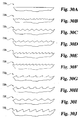
- elastic body 15 may include a wide variety of surface configurations, such as macro-surface patterns, or protuberances, as seen in FIGS. 14A-14J, showing side views or top views of top portions of elastic bodies with various surface features.
- the pattern may be a dove-tail pattern 200, a circular pattern 205, a square pattern 210, a conical pattern 215, various wave patterns 220 and 225 and random, irregular patterns 230.
- a fiber 240 may be disposed in elastic body 241 and may project from the surface 242 thereof to form a fibrous pattern 235.
- Fiber 240 may be disposed as a loop projecting from the surface of the elastic body, its ends may project from the surface of the elastic body, or the fiber may have a wide variety of other appropriate configurations.
- the fiber may be a short, polymeric fiber, such as one that is cut to less than about one inch.
- the fiber may, alternatively, be a continuous polymeric fiber.
- the fiber may further be braided, and may be woven or non-woven.
- the macro-surface patterns are preferably formed during formation of elastic body 15.
- outer surface 16 of elastic body 15 may also be physically modified after formation of elastic body 15 by, for example, laser drilling or thermal deformation. Physical modifications include, for example, a microtexturized surface formed by bead-blasting, plasma etching or chemical etching. Procedures for modifying various surfaces in this manner are well known in the art.
- the implant may include only elastic body 15 having one or more of the outer surface features as described above, without the outer resorbable shell.
- the surface features are expected to provide a certain level of fixation to the surrounding tissues for improved resistance to migration and/or expulsion.
- the implant may include an elastic body that is surrounded by a supporting, or otherwise constraining, member wherein the supporting member is surrounded by a resorbable shell as described herein.
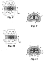
- implant 400 includes a load bearing elastic body 15 that is surrounded by a supporting member 34.
- supporting member 34 may be a preferably flexible, peripheral supporting band that is disposed circumferentially about elastic body 15 as seen in FIG. 5, leaving upper and lower surfaces 35 and 36, respectively, of elastic body 15 free from the supporting band.
- portions of upper and lower surfaces 35 and 36, respectively, of elastic body 15 are exposed to directly contact outer shell 30. This exposure minimizes the amount of material needed to construct the supporting member, yet still effectively provides, for example, lateral support.
- the amount of the upper and lower surfaces of elastic body 15 that are exposed may vary, typically at least about 50%, preferably at least about 70%, more preferably at least about 80% and most preferably at least about 90% of the surfaces are exposed.
- nucleus pulposus implant 500 that includes elastic body 15 as described above, is reinforced with supporting member 37, which takes the form of a jacket.
- the jacket preferably completely surrounds elastic body 15.
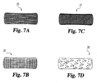
- Suitable supporting members including reinforcing outer bands, covers, or other jackets, may be formed from a wide variety of biocompatible polymers, metallic materials, or combination of materials that form a strong but flexible support to prevent excessive deformation, including lateral (horizontal) deformation, of the core under increasing compressive loading.
- Suitable materials include non-woven, woven, braided, or fabric materials made from polymeric fibers including cellulose, polyethylene, polyester, polyvinyl alcohol, polyacrylonitrile, polyamide, polytetrafluorethylene, polyparaphenylene terephthalamide, and combinations thereof.
- suitable materials include non-reinforced or fiber-reinforced elastomers such as silicone, polyurethane, copolymers of silicone and polyurethane, polyolefins, including polyisobutylene and polyisoprene, neoprene, nitrile, vulcanized rubber, and combinations thereof.
- a combination, or blend, of silicone and polyurethane is used.
- the vulcanized rubber is preferably produced as described above for the nucleus pulposus implants.
- Supporting members 34 and 37 are advantageously made from a porous material, which, in the case of an elastic body made from a hydrogel, or other hydrophilic material, allows fluid circulation through the elastic core body to enhance pumping actions of the intervertebral disc.
- Supporting members may further be formed from carbon fiber yarns, ceramic fibers, metallic fibers or other similar fibers as described, for example, in U.S. Patent No. 5,674,295.
- FIGS. 7A-7D show supporting bands of various patterns, typically made from various braided materials (bands 25, 26 and 27), or porous materials (band 28), as described above. It is also understood the jackets may also be formed of such patterns. It is realized that the braided materials may also be porous.
- Supporting members 34 and 37 preferably decrease lateral deformation, compared to deformation of an implant without the supporting member, as desired.
- Supporting members 34 and/or 37 may, for example, decrease lateral deformation by at least about 20%, preferably at least about 40%, more preferably by at least about 60% and most preferably by at least about 80%.
- An implant, such as one that includes an elastic body, having such a supporting member will be flexible and otherwise resilient to allow the natural movements of the disc and provides shock absorption capability at low to moderate applied stress, but will resist excessive deformation for disc height maintenance under high loading conditions.
- low applied stress includes a force of about 100 Newtons to about 250 Newtons
- moderate stress includes a force of about 250 Newtons to about 700 Newtons
- high loading conditions, or high stress includes a force of above about 700 Newtons.
- the supporting member is flexible, in that it may be folded, or otherwise deformed, but is substantially inelastic, so that the implant is more fully reinforced or otherwise supported.
- the elastic body may be covered by the jacket supporting member, or the band supporting member may be wrapped around the circumference of the elastic body.
- the hydrogel may be dehydrated a desired amount prior to being covered by the jacket, or prior to wrapping the band around the circumference of the hydrogel body.
- the hydrogel elastic body may be exposed to saline outside of the body, or may be inserted into the disc space wherein it will be exposed to body fluids in situ, and the body will absorb water and swell.
- the swelling or expansion of the hydrogel elastic body in the horizontal direction is controlled by the amount of slack designed in the band.
- the elastic body After the limited allowable horizontal expansion is reached, the elastic body is forced to expand mostly in the vertical direction until reaching equilibrium swelling under the in vivo load. As the upper and lower surfaces of the elastic body are not substantially constrained, the vertical expansion is mainly controlled by the applied stress and the behavior of the hydrogel material.
- an implant reinforced with a peripheral supporting band as described above that is surrounded by a resorbable outer shell may be further reinforced with one or more straps.
- the straps may be advantageous in preventing the peripheral supporting band described herein from slipping, or otherwise sliding off the implant.
- at least one strap 420 extends along upper surface 35 and at least one strap 430 extends along lower surface 36 of elastic body 15 of implant 400. Ends 421 of strap 420 and ends 431 of strap 430 are each preferably connected, or otherwise attached, to peripheral supporting band 34'.
- the point of attachment may be any location that will secure the strap, including at the upper margins 138 of the band, lower margins 139 of the band or any region between the upper and lower margins.
- one continuous strap may be utilized that extends completely around the implant, or the strap utilized may be in one, two or multiple pieces, as long as the combination of straps are sufficient to prevent excessive slipping and or sliding of the supporting band.
- more than one strap may extend along upper surface 35 and more than one strap may extend along lower surface 36 of elastic body 15, as seen, for example, in FIGS. 10 and 11 of implant 500, wherein straps 520, 530, 540 and 550 are shown attached, or otherwise connect to supporting member 34". It is realized that the straps may be present in one or more pieces.
- straps 520 and 530 may form a single strap, as may straps 540 and 550, or may all combine to form a single strap.
- kits designed for forming the intervertebral disc nucleus pulposus implants that include the outer shell described above are provided.
- a kit may include a load bearing elastic body as described above, along with a container of material to form the outer, preferably resorbable, shell.
- the material may be selected from the materials as described above.
- the container that houses the material that forms the shell may be made from a wide variety of materials that are compatible with the outer shell material, including glass and plastic.
- the kit may further include a supporting member, such as a supporting band, jacket or other outer cover as described above.
- the kits include sterile packaging which secures the kit components in spaced relation from one another sufficient to prevent damage of the components during handling of the kit. For example, one may utilize moldad plastic articles known in the art having multiple compartments, or other areas for holding the kit components in spaced relation.
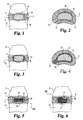
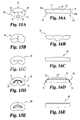
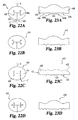
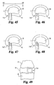
- implant 40 includes a load bearing elastic body 41 with shape memory and having a first end 42 and a second end 43 that are positioned adjacent to a central portion 44 to form at least one inner fold 45.
- Inner fold 45 preferably defines at least one aperture 46 which is advantageously arcuate.
- the elastic body is deformable, or otherwise configurable, manually, for example, from this first folded, or otherwise relaxed configuration shown in FIG.
- implant 40 includes surface depressions 47, or other surface irregularities as more fully described below, that form inner fold 45 when the implant is in its relaxed configuration.
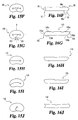
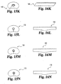
- Ends 42 and 43 have end surfaces 42a and 43a, respectively, that are generally flat, and substantially parallel, or perpendicular in other forms, to an axis X passing through the width of the implant in its relaxed configuration, wherein the ends may abut each other as seen in FIGS. 15A, 15B and 15E-15N.
- the ends of the implant may each alternatively abut the central portion of the implant, as shown for implants 60 and 70 in FIGS. 15C and 15D, respectively, to form a generally bi-lobed or binocular-shaped implant.
- one end of the implant may be tapered, or otherwise specifically shaped, and the other end may be shaped complementary to the tapered, or otherwise shaped, end.
- either one or both sides 96a and 96b of the ends of the nucleus pulposus implant may be tapered.
- both sides of end 93 of implant 90 are tapered to form a pointed end, such as a generally V-shaped end, that advantageously fits into a complementary-shaped (e.g., V-shaped) depression 95 defined by end 92.
- An implant having only one inner fold that defines one aperture and ends that are similarly configured as ends 92 and 93 is shown in FIGS. 15J and 16J.
- each of the ends of the implant may be oppositely tapered as seen in FIGS. 15G and 16G. That is, side 108a of end 102 of implant 100 and opposite side 109b of end 103 are tapered as seen in FIG. 15G and 16G. End surfaces 102a and 102b of implant 100 are transverse to axis X when the implant is in its relaxed configuration shown in FIG. 15G. In those embodiments where the ends of the implants are tapered, or otherwise shaped, it is preferred that, when the ends of the implants contact each other or the central or other portion of the implant, an implant is formed that is uniform along the length of the implant through the region of contact.
- the implant may assume a wide variety of shapes, it is typically shaped, in its folded, relaxed configuration, to conform to the shape of the natural nucleus pulposus.
- the implants may be substantially elliptical when in their folded, relaxed, configurations in some forms of the invention.
- the shape of the implants in their folded configurations may be generally annular-shaped or otherwise shaped as required to conform to the intervertebral disc cavity.
- the implants when they are in their unfolded, non-relaxed, configuration, such as their substantially straightened configuration, they may also assume a wide variety of shapes, but are most preferably generally elongated, and preferably generally cylindrical, or other shape as described herein.
- the folding implant may have a surface that includes surface projections that further aid in allowing short-term deformation of the implant without permanent deformation or other damage as described above.
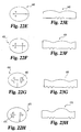
- implant 70 includes a load bearing elastic body 71 having a first end 72, a second end 73 and a central portion 74.
- Inner fold 75 defines an aperture 76 and includes an inner fold surface 77 having wrinkles, or projections 78 thereon. Projections 78 of inner fold surface 77 extend into aperture 76.
- the wrinkles, or surface projections extend along the entire length of elastic body 71, including central portion 74.
- Other implants having wrinkled inner fold surfaces are seen in FIGS. 15E and 16E and other wrinkle configurations upon folding the implant are seen in FIGS. 15K-15N and 16K-16N.
- FIGS. 22A-22Q, 23A-23Q and 24-27 Other folding implants are shown in FIGS. 22A-22Q, 23A-23Q and 24-27.
- implants 400-620 are shown that have a plurality of inner folds, ranging from, for example, two to about six.
- these implants, as well as the above-discussed folding implants have first and second ends that are formed from first and second arms, respectively, of the implants.
- first end 402 of implant 400 is formed from a first arm 408 connected to, or otherwise associated with, one end 404a of central portion 404.
- Second end 403 is formed from a second arm 409 connected to, or otherwise associated with, opposing end 404b of central portion 404.
- Surface depressions 405 or other surface irregularities define inner folds 406 when the implant is in its relaxed configuration.
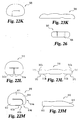
- each of the arms connected to the central portions of the implant are the same length, as seen in FIGS. 15A-15J, 15L-15N, 22A-22B, 23A-23B, 22D-22E, 23D-23E, 22G and 23G.
- one of the arms is shorter than the other arm.
- second arm 429 of implant 420 is shorter than first arm 428, wherein each arm is connected to an end of central portion 424.
- the ends of the implant abut each other along a plane extending along axis X and passing through the width of the implant, resulting in a center or central closure C of the implant as seen, for example, in FIG. 22A.
- the ends of the implant abut each other along a plane extending parallel to a plane extending along axis X and passing through the width of the implant, resulting in an off-center closure C' of the implant as seen, for example, in FIG. 22C.
- the differential length of the arms of the implants can facilitate implantation and proper positioning of the implants in the disc space as more fully described below.
- each end of the implant may include a surface that has a surface depression, such as surface depression 421 or 422, as seen in FIG. 23C, that forms a portion of the inner fold such that when the ends of the implant contact each other, an inner fold is formed from the combination of surface depressions.
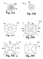
- the apertures defined by the inner folds may have a variety of cross-sectional shapes, including substantially annular or otherwise ring-shaped, substantially oval or otherwise elliptical-shaped, star-shaped or other various shapes known to the skilled artisan.
- the star-shaped pattern includes a plurality of finger-like or otherwise elongated projections 465 or 475 as seen, for example, in FIGS. 22G and 22H, respectively.
- FIGS. 221, 231, 24, 22K, 23K and 26 show further details of implants of the present invention.
- apertures, or channels, 486 and 506, can be seen in FIGS. 24 and 26, respectively, showing implants 480 and 500, respectively.
- implant 490 is shown that includes all of the features of the aforementioned implants, including a load bearing body 491, a first arm 498 having a first end 492, a second arm 499 having a second end 493, and surface depressions 497.
- implant 490 includes a central portion 494 that extends along the full width of implant 490 from one end of the implant to an opposing edge of the implant.
- end surfaces 492a and 493a abut, and are otherwise in contact with, central portion 494 when implant 490 is in its folded configuration as seen in FIG. 22J.
- At least one end of the implants may be curved, or otherwise arcuately-shaped or rounded.
- first end 512 and second end 513 each have an inner edge 512b and 513b, and an outer edge, 512a and 513a, respectively.
- Outer edges 512a and 513a are shown as rounded and can facilitate implantation and proper positioning of the implants in the disc space as more fully described below.
- the rounded edges allow for better conformity of the implant to the disc space.
- the dome-shaped, or otherwise concave-shaped, endplates may lead to increased stress concentrated at the edges of the implant.
- the rounded edges reduce such stress. In this manner, there is a smaller likelihood of the implant penetrating the endplate, and the durability of the implant is improved. Bone remodeling based on the shape of the implant is also reduced.
- Implant 610 is shown wherein both ends of the implants have edges that are curved or otherwise rounded.
- Implant 610 includes body 611 having first arm 613 and second arm 614.
- First arm 613 and second arm 614 include ends 613a and 614a, respectively, which both preferably have rounded edges 613b and 614b, respectively, although only one of the ends may have such a rounded, straight or other shaped edge.
- end 614a of second arm 614 is tapered, or otherwise has a decreased diameter compared to end 613a of first arm 613.
- first arm 613 is shorter than second arm 614.
- the bodies forming the implants have a top surface T for contacting an upper vertebral endplate of an intervertebral disc and a bottom surface B for contacting a lower vertebral endplate of the intervertebral disc as seen, for example, in FIG. 27.
- the implants have an external side surface E that includes at least one groove G extending along the side surface that advantageously further relieves the compressive force on the external side E of the implant when the implant is deformed into a substantially straightened, or otherwise unfolded configuration and thus further allows extensive short-term deformation without permanent deformation, cracks, tears or other breakage.
- implant 620 shown in FIGS. 22N, 23N and 27 includes a load bearing body 621 that has a top surface T, a bottom surface B, an internal side surface I and an external side surface E.
- a plurality of grooves G are disposed along external side surface E that typically extend from the top surface to the bottom surface of the implant.
- FIGS. 220 and 230 depict implant 570, which is similar to implant 620, with the exception that implant 570 includes a second arm 572 that is smaller than first arm 571, resulting in an off-center closure C' as more fully described above.
- the top and bottom contact surfaces of the implants are configured to be complementary to the top and bottom endplates of an intervertebral disc, respectively.
- the top and bottom contact surfaces of the implants may be convex, to conform to the respective concave intervertebral disc endplates.
- the implants are preferably one-piece implants, they may also be composed of one or more pieces.
- an implant may be composed of a separate central portion and first and second arms, wherein the arms are associated or otherwise attached to the central portion as described herein.
- the apertures defined by the inner folds of the implants described above have a radius of at least about 1 mm.
- a reinforcing material may be included at the inner fold surface to further improve the structural integrity of the implant.
- the reinforcing material may be a fabric that is either woven, or non-woven, and may be formed from braided fibers for further strength.
- the reinforcing material may be positioned on the inner fold surface, may project therefrom or may be entirely embedded under the inner fold surface.
- the implant may be formed as a single piece, or may be formed of more than one piece that is connected to the other pieces that form the assembled implant by fabric that may be made from braided or other fibers, or may be connected by some other components or manner, such as by use of adhesives, or other methods of connecting such components together.
- these implants are designed to be used without an anchoring outer shell, they, as well as all of the implants described herein, may form the core elastic body of an implant that includes the outer shell described herein.
- the implants may obtain their shape memory characteristics in a variety of ways.
- the implants may be formed in a mold into a desired final shape, and, when deformed from this final shape by application of an external force, will return to the final shape upon release of the force.
- a nucleus pulposus implant in yet another embodiment, has a locking feature, with optional shape memory characteristics, and thus may also resist being expelled from the disc cavity to some extent.
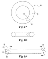
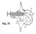
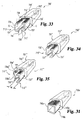
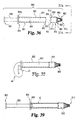
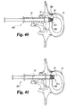
- an implant 300 includes a load bearing elastic body 301 having a first end 302 and a second end 303. The ends are typically configured for mating engagement with each other.
- Elastic body 301 has a first, locked configuration wherein first end 302 and second end 303 are matingly engaged to each other as seen more particularly in FIG. 17.
- elastic body 301 When elastic body 301 has shape memory characteristics, elastic body 301 is deformable, manually, for example, into a second, substantially straightened, non-relaxed configuration for insertion into an intervertebral disc space, as seen in FIG. 19, and may automatically be configured or otherwise retumed back into the first, locked, relaxed configuration after insertion due to its shape memory characteristics. In those cases where the elastic body does not have shape memory characteristics and the elastic body is configurable into a locked and/or straightened configuration, and in those cases where the elastic body has shape memory characteristics, the elastic body may also be placed into its locked configuration with the assistance of external force.
- end 302 defines an internal channel 304 as seen in FIG. 19 whereas end 303 is configured to conform to the shape of internal channel 304.
- the channel may take the form of a wide variety of shapes, as long as the ends of the elastic body may be matingly engaged to form a locked configuration. As seen in FIG. 19, the channel is somewhat hour-glass shaped. Manual, or other force, may be applied to end 303 so that it may be temporarily deformed, or configured, sufficiently to pass through narrowed passage 305 within internal channel 304. Once properly positioned, end 303 will be secured within channel 304, as end edges 303a and 303b are braced against channel edges 304a and 304b, respectively.
- one end of an implant with a locking feature may be friction-fit within the internal channel present in the other end of the implant.
- the friction-fit may arise as a result of the relative size differences between the inner diameter of the channel formed by one end and the outer diameter of the other end of the implant.
- the outer surface of one end, and/or the inner surface of the channel defined by the other end may include surface roughenings as described herein that aid in achieving the friction-fit.
- the implant may also be constructed from the biocompatible polymeric materials as described above.
- the implants When the implants are formed from an elastic material, such as a hydrogel, or other similar hydrophilic material, or include the resorbable outer shell, they may advantageously deliver desired pharmacological agents.
- the pharmacological agent may be a growth factor that may advantageously repair the endplates and/or the annulus fibrosis.
- the growth factor may include a bone morphogenetic protein, transforming growth factor- ⁇ (TGF- ⁇ ), insulin-like growth factor, platelet-derived growth factor, fibroblast growth factor or other similar growth factor or combination thereof having the ability to repair the endplates and/or the annulus fibrosis of an intervertebral disc.
- TGF- ⁇ transforming growth factor- ⁇
- insulin-like growth factor insulin-like growth factor
- platelet-derived growth factor platelet-derived growth factor
- fibroblast growth factor or other similar growth factor or combination thereof having the ability to repair the endplates and/or the annulus fibrosis of an intervertebral disc.
- the growth factors are typically included in the implants in therapeutically effective amounts.
- the growth factors may be included in the implants in amounts effective in repairing an intervertebral disc, including repairing the endplates and the annulus fibrosis. Such amounts will depend on the specific case, and may thus be determined by the skilled artisan, but such amounts may typically include less than about 1% by weight of the growth factor.
- the growth factors may be purchased commercially or may be produced by methods known to the art.
- the growth factors may be produced by recombinant DNA technology, and may preferably be derived from humans.
- recombinant human bone morphogenetic proteins including rhBMP 2-14; and especially rhBMP-2, rhBMP-7, rhBMP-12, rhBMP-13, and heterodimers thereof may be used.
- any bone morphogenetic protein is contemplated including bone morphogenetic proteins designated as BMP-1 through BMP-18.
- BMPs are available from Genetics Institute, Inc., Cambridge, Massachusetts and may also be prepared by one skilled in the art as described in U.S. Patent Nos. 5,187,076 to Wozney et al.; 5,366,875 to Wozney et al.; 4,877,864 to Wang et al.; 5,108,922 to Wang et al.; 5,116,738 to Wang et al.; 5,013,049 to Wang et al.; 5,106,748 to Wozney et al.; and PCT Patent Nos. WO93/00432 to Wozney et al.; WO94/26893 to Celeste et al.; and WO94/26892 to Celeste et al.
- All bone morphogenic proteins are contemplated whether obtained as above or isolated from bone. Methods for isolating bone morphogenetic protein from bone are described, for example, in U.S. Patent No. 4,294,753 to Urist and Urist et al., 81 PNAS 371, 1984.
- the pharmacological agent may be one used for treating various spinal conditions, including degenerative disc disease, spinal arthritis, spinal infection, spinal tumor and osteoporosis.
- Such agents include antibiotics, analgesics, anti-inflammatory drugs, including steroids, and combinations thereof.
- Other such agents are well known to the skilled artisan.
- These agents are also used in therapeutically effective amounts. Such amounts may be determined by the skilled artisan depending on the specific case.
- the pharmacological agents are preferably dispersed within the hydrogel, or other hydrophilic, implant for in vivo release, and/or, with respect to the implants with the resorbable outer shell, may be dispersed in the outer shell.
- the hydrogel can be cross-linked chemically, physically, or by a combination thereof, in order to achieve the appropriate level of porosity to release the pharmacological agents at a desired rate.
- the agents may be released upon cyclic loading, and, in the case of implants including a resorbable outer shell, upon resorption of the shell.
- the pharmacological agents may be dispersed in the implants by adding the agents to the solution used to form the implant, by soaking the formed implant in an appropriate solution containing the agent, or by other appropriate methods known to the skilled artisan.
- the pharmacological agents may be chemically or otherwise associated with the implant.
- the agents may be chemically attached to the outer surface of the implant.
- the implants described herein may have embedded therein small metal beads or wire for x-ray identification.
- implant 10 may be formed by first forming elastic body 15 and then forming the outer shell. Methods of forming elastic body 15 are well known in the art.
- the elastic body is made of elastomeric materials, such as powdered elastomers including, for example, styrene-ethylene/butylene block copolymers
- the powdered elastomer may be placed into an appropriate mold and may be compressed and heated to melt the powder. The mold is then cooled to room temperature.
- the elastic body is made from a hydrogel, such as a polyvinyl alcohol
- the polyvinyl alcohol powder may be mixed with a solvent, such as, for example, water or dimethylsulfoxide, or combinations thereof, and heated and shaken until a uniform solution is formed.
- the solution may then be poured into a mold, such as a rubber mold, and may be cooled at an appropriate temperature, such as about 0°C to about -80°C, for several hours to allow for crystallization.
- a mold such as a rubber mold
- the hydrogel can be partially or completely hydrated by soaking and rinsing with water but, in certain preferred embodiments, may remain dehydrated so that it may be inserted through a smaller aperture in the annulus fibrosis.
- an incision may be made in the annulus fibrosis, or one may take advantage of a defect in the annulus, in order to remove the natural nucleus pulposus and any free disc fragments within the intervertebral disc space.
- the disc space is then distracted to a desired level by distractors or other devices known to the skilled artisan for such purposes.
- elastic body 15 may be implanted into the intervertebral disc space utilizing devices well known in the art and as described in U.S. Patent Nos. 5,800,549 and 5,716,416.
- outer shell precursor material may flow out of the disc space. This excess material should be promptly removed before it sets or otherwise cures.
- the outer shell material may be injected, or otherwise introduced, into the disc space utilizing devices that are well known in the art, such as syringes, sealant/caulk guns, automatic liquid injectors, and applicators that include, for example, two separate syringes which allow for simultaneous mixing of the components in a static mixer and delivery to the site, and may be injected either prior to or after introduction of the implant into the disc space.
- the distractor is then removed, any excess precursor material seeping out of the disc space is removed and the precursor material within the disc space is cured to form the outer shell.
- the elastic body may already be surrounded by the outer shell, which may be in a partially or fully hardened state but preferably remains deformable, prior to introducing the elastic body into the intervertebral disc space.
- the device preferably includes an elongated member having a lumen extending longitudinally therethrough for loading of the desired implant, a tip portion for controlling passage of the implant out of the delivery tool and a plunger or other elongated member or other device for pushing the implant through the tool and into an intervertebral disc cavity.
- the tip portion preferably includes a movable member that may be moved from a first, closed position in which it blocks the passage of a spinal disc implant through the lumen, and out of the distal end, of the elongated member into which the spinal implant is loaded and otherwise housed.
- the tip portion may also preferably be moved to a second, open position, wherein egress of the spinal implant is allowed.
- device 700 includes an elongated member 701, such as a syringe housing 702 or other elongated housing or barrel that defines a cavity, or lumen, 703 that extends along its length, and has a proximal end 704 and a distal end 705. Proximal end 704 defines a flange 704a.
- Inner surface 703a of cavity, or lumen, 703 is preferably configured for passage of a spinal nucleus pulposus implant.
- inner surface 703a is preferably smooth.
- Device 700 further includes a plunger 706, or elongated or other member.
- Plunger 706 includes an elongated member, or rod, 720 having proximal end 707 and distal end 709 that may be utilized to push a nucleus pulposus implant that may be disposed in cavity 703 through the housing and ultimately into an intervertebral disc space.
- Distal end 709 of plunger 706 may include a plunger tip 721 that is configured to contact an implant during extrusion.
- plunger tip 721 is preferably similar to that of elongated housing member 701.
- Proximal end 707 of plunger 706 includes a plunger handle 722.
- Plunger 706 may include one or more components that may facilitate extrusion of the implant by pneumatic, hydraulic or mechanical force, or by manual pushing or impacted force.
- the plunger can be in the form of a pushing or impacted plunger, a syringe plunger, a caulk gun plunger, or a screw-driven plunger as known in the art.
- Device 700 further includes component, or tip portion, 710 having a proximal end 713 and a distal end 712 wherein tip portion 710 may be integral or detachable.
- proximal end 713 of tip portion 710 may be matingly engageable to, or is otherwise connected or associated with, distal end 705 of housing 702 of member 701.
- tip portion 710 may include a top wall 730, a bottom wall 735, a side wall 740 and an opposing side wall 745.
- Tip portion 710 defines a cavity, or lumen, 731 extending longitudinally therethrough wherein lumen 731 is continuous, and otherwise in fluid communication, with lumen 703 of elongated housing member 701.
- tip portion 710 may be configured to accommodate a spinal disc implant to be delivered.
- Height H of tip portion 710 may have a height similar to or larger than the disc space height depending on whether disc space distraction is required.
- length L of the tip portion may be chosen so that tip portion 710 will preferably not substantially extend past the inner wall of the annulus fibrosus as described more fully below. Different dimensions of the tip portion may be determined by the skilled artisan.
- Tip portion 710 is preferably configured to enter an aperture in an annulus fibrosus for delivery of a spinal nucleus pulposus implant or other spinal implant.
- tip portion 710 is shown as a rectangular tube in FIG. 29, it may have a wide variety of shapes, including cylindrical, square, hexagonal or other multi-sided shape.
- Surface 732 of top wall 730 and surface 733 of bottom wall 735 contact the endplates during delivery of the implant, and may have surface features 738 that help anchor, engage or otherwise secure the tip to the opposing endplates. Examples of such surface features, such as surface roughenings, are shown in FIGS. 30A-30J and include teeth 738c-738g, in the form of serrations or spikes (FIGS.
- ridges 738i and 738j (FIGS. 30I and 30J) a textured surface 738b (FIG. 30B) or a non-textured surface 738a (FIG. 30A).
- the teeth or ridges may be directional and may restrict movement in a single direction, as seen in FIGS. 30D, 30E, 30F, and 30G for example.
- one side wall may be shorter than the other to aid delivery and placement of the spinal disc implants described herein.
- delivery device 700a includes tip portion 710a having side wall 740a that is shorter than side wall 745a.
- FIG. 32 shows one way in which delivery of an implant 40 is aided. For example, as implant 40 exits the device, it veers to the shorter side wall and will subsequently fold up in the disc space.
- the top and bottom walls of the tip portion may be partially open to alleviate any possible constriction of the implant as it exits the device and is delivered into a disc space.
- tip portion 710' of device 700' may include a top wall 730' having an opening 739 and a bottom wall 735' having an opening 741, wherein both openings may extend from a proximal end 712' to a distal end 713' of tip portion 710'.
- tip portion 710' forms opposing arms 736 and 737, each having an inner surface I and an outer surface O. Inner surfaces I are preferably concave and preferably accommodate a spinal disc implant.
- both arms 736 and 737 of tip portion 710' are shown in FIG. 33 as having the same length, one of the arms may be shorter than the other to, for example, aid placement of the folding implants described herein.
- arm 736' of tip portion 710" of device 700" is shorter than arm 737'.
- one of the arms of the tip portion may be movable and the other non-movable or otherwise stationary.
- arm 737" of tip portion 710"' of device 700' is similar in configuration as arm 737' and is preferably non-movable and further preferably otherwise rigid.
- Arm 736" may also be non-movable or otherwise rigid, but it may include both a non-movable portion 736a" and a movable, flexible or otherwise elastic portion 736b" so that arm 736" may move, or be bent, and form a closed configuration.
- arm 736" may be bent, preferably at an angle ⁇ of greater than about 30°, further preferably between about 45° to about 90°, and typically about 60°. It is preferred, especially when the tip portion also functions as a distractor, that the movable portion of the arm has a height that is less than the height of a disc space, and/or the height of the arm at its distal end is shorter than at its proximal end, so that it may move freely. In the closed configuration, the width W of distal end 713"' of tip portion 710"' is narrow, such as about 2 mm to about 10 mm, which makes it easier to guide the tip portion into a small annular opening. Additionally, the implant for delivery will be blocked from exiting the delivery device by arm 736" in its closed configuration.
- movable arm 736" may be moved, radially, for example, to form an open configuration, such as the configuration of arm 736 of device 700' of FIG. 33, under extrusion pressure to expand the annular opening and to allow the implant to exit the device and enter the disc space as described below.
- the movable arm retracts, bends or otherwise moves back to its closed configuration in order to decrease the expansion of the annular opening. It is realized that both arms may also be rigid, flexible or otherwise elastic as desired. Other tip portions that have such open and closed configurations are described below.
- the tip portion has wall support for the top, bottom and side surfaces of the spinal disc implants to be delivered. It is further noted that lumens 703', 703", 703'" of elongated members 701', 701 " and 701 "', respectively, are continuous, and in fluid communication, with cavity 731', 731 ", 731 "', respectively.
- a spinal disc implant delivery device 800 includes an elongated member 801, such as a syringe housing 802 that defines a cavity 803, and has a proximal end 804 with a flange portion 804a and a distal end 805.
- Device 800 further includes a plunger 806, or elongated or other member, having proximal end 807 and distal end 809 that may be utilized to push a nucleus pulposus implant that may be disposed in cavity 803 through the housing, out of the distal end of the housing and ultimately into an intervertebral disc space.
- Device 800 further includes component, or tip portion, 810 having a proximal end 813 and a distal end 812, wherein proximal end 813 is matingly engageable to, or is otherwise connected or associated with, distal end 805 of housing 802 of member 801 which is also seen in FIG. 36.
- Tip portion 810 preferably includes a base member 850 which has a proximal end 851, a distal end 852, and a lumen 853 extending longitudinally therethrough.
- Tip portion 810 further preferably includes at least one movable member that may form a closed configuration as described herein.
- tip portion 810 includes a plurality of movable members 880. Proximal end 881 of movable members 880 abut, or are connected to or are otherwise associated with, distal end 852 of base member 850.
- Movable members 880 have a first, closed configuration wherein they define a channel or cavity 883.
- the members may further have a closed configuration which includes a narrowed distal end.
- Lumen 853 of base member 850 and cavity 883 are preferably in fluid communication.
- Lumen 853 of base member 850 and cavity 803 of housing 802 are also preferably in fluid communication when distal end 805 of housing 802 and proximal end 851 of base member 850 are matingly engaged.
- movable members 880 In their closed configuration, movable members 880 preferably further define an aperture 884, or other opening, at their distal end as best seen in FIG. 37A.
- Aperture 884 is preferably sized and/or configured for ease of insertion of the tip into an annular opening, preferably an undersized or relatively small annular opening.
- the diameter of aperture 884 of movable members 880 may range from about 2 mm to about 10 mm in its closed configuration.
- Movable members 880 are preferably movable, flexible, or otherwise elastic, but in certain forms of the invention may be otherwise rigid, and further have an open configuration wherein movable members 880 are moved, flexed or otherwise bent sufficiently to enable passage of a spinal implant, such as a nucleus pulposus implant described herein, through lumen 853 of base member 850 and through an area circumscribed by the movable members in their open configuration so that the spinal implant may exit the delivery tool and may be inserted into or otherwise positioned in an intervertebral disc space.
- a spinal implant such as a nucleus pulposus implant described herein
- Movable members 880 are preferably placed in their open configuration when, for example, a spinal implant is positioned in housing 802 of syringe 801 and plunger 806, or other elongated or similar member, transmits a force sufficient for translation of the spinal implant through cavity 803 of housing 802, lumen 853 of base member 850 and cavity 884 defined by movable members 880.
- a spinal implant is positioned in housing 802 of syringe 801 and plunger 806, or other elongated or similar member, transmits a force sufficient for translation of the spinal implant through cavity 803 of housing 802, lumen 853 of base member 850 and cavity 884 defined by movable members 880.
- Contact of the inner surfaces of movable members 880 with, and continued translation of, a spinal implant toward distal end 812 of device 800 forces the radial flexing, bending or movement of movable members 880 as more fully described below.
- Movable members 880 and base member 850 may be engaged, connected or otherwise associated with each other in a variety of ways, including use of an adhesive. Moreover, movable members 880 and base member 850 may be integral. Base member 850 may also be integral with syringe housing 802, or may be attached by adhesive or other manner of attachment described herein and/or known to the skilled artisan. For example, base member 850 may have an inner surface 854 defining lumen 853 that is tapered as desired to varying degrees so that base member 850 may be associated with syringe housing 802 by friction fit. Other mechanical interlocking methods known to the art may also be utilized to couple proximal end 851 of base member 850 to distal end 805 of housing 802 of syringe 801.
- Tip portion 810 may include a plurality of movable members and may assume a wide variety of shapes. As seen in FIG. 37A, tip portion 810 is round and includes 16 movable members 880, although more or less may be present as desired.
- the tip portion may include 8 movable members 780b, 780c and 780d (tip portion 810b-810d, respectively) as seen in FIGS. 37B-37D, 4 movable members 780e (tip portion 810e) as seen in FIG. 37E or 2 movable members 780f (tip portion 81 0f) as seen in FIG. 37F.
- the movable members may contact a neighboring movable member or may be variously spaced apart. For example, FIGS.
- 37D, 37E and 37F show movable members, some of which are spaced apart by space S.
- the tip portions may assume a wide variety of cross-sectional shapes, including circular, elliptical, square, rectangular or other multi-sided or geometric shape.
- the housing members, plunger members and base members described herein may be made from a variety of materials, including metals known to the art, such as stainless steel and titanium alloys, polymers known to the art, including polyethylene, polypropylene, polyetheretherketone and polyacetal.
- Movable members, such as movable members 880 may also be made from a variety of materials, preferably those which are flexible or otherwise elastic, and allow for flexing, bending or pivoting.
- Movable members 880 may be made from the same materials as the housing members, plunger members and base members described herein.
- a method for implanting a prosthetic intervertebral disc having shape memory is also described, in which an implant including a load bearing elastic body having a first end and a second end positioned adjacent to a central portion to form at least one inner fold as described above is provided.
- the disc space may be distracted if necessary and all or a portion of the nucleus pulposus may be removed.
- the implant 40 may be deformed by, for example, manual force into a substantially straightened, non-relaxed configuration for insertion through an aperture formed in the annular fibrosis as indicated in FIG. 20, and as best seen in FIG. 21.
- the aperture may be formed through deterioration or other injury to the annulus fibrosis, or may be made by purposely incising the annulus.
- the implant may then be positioned in a delivery tool 310 known in the art, such as that described in U.S. Patent No. 5,716,416, and inserted through aperture 18 in annulus 19, although utilization of the delivery devices or tools described more fully herein is preferred.
- a delivery tool 310 known in the art, such as that described in U.S. Patent No. 5,716,416, and inserted through aperture 18 in annulus 19, although utilization of the delivery devices or tools described more fully herein is preferred.
- a portion, or substantially all, of the natural nucleus pulposus may be removed from the intervertebral disc space, depending on the circumstances, prior to introduction of the implant into the intervertebral disc space.
- the implant When implanting an implant that includes a locking feature, or other implant with shape memory as described herein, a similar protocol is followed. Additionally, with respect to an implant with a locking feature, the implant may be placed into the locked configuration with external force, imposed by, for example, medical personnel. It is noted that, due to the symmetrical features of a variety of the implants described herein; the implant may be inserted into the disc space by a wide variety of approaches, including anterior and posterior approaches.
- a method for implanting a prosthetic intervertebral disc having shape memory may be practiced with device 800 as depicted in FIGS. 38-44.
- implant 40 is deformed by, for example, manual force into a substantially straightened, non-relaxed, unfolded, configuration for insertion through an aperture formed in the annular fibrosis, it is loaded, or otherwise positioned in cavity 803 of syringe housing 802.
- implant 40 may be straightened as it is inserted into cavity 803 at proximal end 804 of housing 802.
- Distal end 809 of plunger 806 may then be inserted into cavity 803 from proximal end 804 of housing 802.
- Device 800 loaded with implant 40, may then be positioned adjacent aperture 18 in annulus 19 as seen in FIG. 40.
- Distal end 882 of movable members 880 are preferably positioned through aperture 18 in annulus 19 and preferably extend into intervertebral disc space 20 surrounded by annulus 19, as seen in FIG. 40.
- Force is applied to plunger 806, preferably at its proximal end 807, to contact end 42 of implant 40 for translation of the implant towards distal end 812 of delivery tool 800.
- the force preferably will allow contact of distal end 809 of plunger 806 with an adjacent end of the implant and may be provided manually, with a mechanical pressurization device, including a caulk gun, or by other devices and methods known to the skilled artisan, including the force generator described in U.S.
- Patent No. 5,800,849 as well as other hydraulic, pneumatic, manual or power-assisted hydraulic force generators. It is noted that, when utilizing device 700, 700', 700" or 700"', the tip portion of these devices may act as a distractor to distract the disc space, although a distractor may also be used depending on the circumstances and preference of the surgeon.
- movable members 880 As implant 40 enters cavity 883 (cavity 883 being seen in FIG. 36) defined by movable members 880 in their closed configuration, movable members 880 begin to move radially, or otherwise flex or bend radially, as seen in FIG. 41. Radial movement of movable members 880 allows the movable members to contact the surrounding annular tissue and press or otherwise push the tissue such that the annular defect, or other opening such as aperture 18, is dilated. This allows implant 40 to exit distal end 812 of delivery device 800 and enter intervertebral disc space 20 as seen in FIGS. 41-43, wherein movable members 880 are seen in their open configuration.
- implants described herein having arms of differential length can facilitate implantation and proper positioning of the implants in the intervertebral disc space.
- an implant having an off-center closure may prevent possible excessive rolling of the implant during insertion so that the implant will be positioned such that the length of the implant extends substantially parallel to the coronal plane of a patient's body.
- distal end 809 of plunger 806 may retain movable members 880 in their open configuration as end 42 of implant 40 approaches distal end 812 of delivery device 800 prior to completely exiting the device.
- the plunger is translated a sufficient amount distally to allow implant 40 to exit the device, if necessary, the plunger is retracted, or translated in a proximal direction to ensure the deforming members are in their closed configuration as seen in FIG. 44.
- Delivery device 800 is then removed. As seen in FIG. 44, implant 40 is properly positioned in intervertebral disc space 20.
- FIGS. 45-48 placement of the spinal implant delivery devices having tip portions 710, 710', 710" and 710"', respectively, in an intervertebral disc cavity 20, is shown.
- the distal ends of the tip portions preferably extend slightly, e.g., about 1 mm to about 10 mm, past the inner face, or wall, I of annulus fibrosus 19.
- FIG. 49 is a view along line 49-49 of FIG. 45 showing placement of tip portion 710.
- the preferred delivery instrument, or device, and methods described herein are compatible with Medtronic Sofamor Danek's MetRxTM microdiscectomy system and surgical procedures.
Landscapes
- Health & Medical Sciences (AREA)
- Engineering & Computer Science (AREA)
- Biomedical Technology (AREA)
- Orthopedic Medicine & Surgery (AREA)
- Transplantation (AREA)
- Neurology (AREA)
- Life Sciences & Earth Sciences (AREA)
- Public Health (AREA)
- Heart & Thoracic Surgery (AREA)
- Vascular Medicine (AREA)
- Cardiology (AREA)
- Animal Behavior & Ethology (AREA)
- General Health & Medical Sciences (AREA)
- Oral & Maxillofacial Surgery (AREA)
- Veterinary Medicine (AREA)
- Physical Education & Sports Medicine (AREA)
- Chemical & Material Sciences (AREA)
- Dispersion Chemistry (AREA)
- Prostheses (AREA)
- Materials For Medical Uses (AREA)
Abstract
Description
- The present invention relates to nucleus pulposus implants.
- The intervertebral disc functions to stabilize the spine and to distribute forces between vertebral bodies. A normal disc includes a gelatinous nucleus pulposus, an annulus fibrosis and two vertebral end plates. The nucleus pulposus is surrounded and confined by the annulus fibrosis.
- Intervertebral discs may be displaced or damaged due to trauma or disease. Disruption of the annulus fibrosis may allow the nucleus pulposus to protrude into the vertebral canal, a condition commonly referred to as a hemiated or ruptured disc. The extruded nucleus pulposus may press on a spinal nerve, which may result in nerve damage, pain, numbness, muscle weakness and paralysis. Intervertebral discs may also deteriorate due to the normal aging process. As a disc dehydrates and hardens, the disc space height will be reduced, leading to instability of the spine, decreased mobility and pain.
- One way to relieve the symptoms of these conditions is by surgical removal of a portion or all of the intervertebral disc. The removal of the damaged or unhealthy disc may allow the disc space to collapse, which would lead to instability of the spine, abnormal joint mechanics, nerve damage, as well as severe pain. Therefore, after removal of the disc, adjacent vertebrae are typically fused to preserve the disc space. Several devices exist to fill an intervertebral space following removal of all or part of the intervertebral disc in order to prevent disc space collapse and to promote fusion of adjacent vertebrae surrounding the disc space. Even though a certain degree of success with these devices has been achieved, full motion is typically never regained after such vertebral fusions. Attempts to overcome these problems have led to the development of disc replacements. Many of these devices are complicated, bulky and made of a combination of metallic and elastomeric components. Thus, such devices require invasive surgical procedures and typically never fully return the full range of motion desired.
- More recently, efforts have been directed to replacing the nucleus pulposus of the disc with a similar gelatinous material, such as a hydrogel. However, there exists a possibility of tearing or otherwise damaging the hydrogel implant during implantation. Moreover, once positioned in the disc space, many hydrogel implants may migrate in the disc space and/or may be expelled from the disc space through an annular defect, or other annular opening. A need therefore exists for more durable implants, as well as implants that are resistant to migration and/or expulsion through an opening in the annulus fibrosis. The present invention addresses these needs.
- Nucleus pulposus implants that are resistant to migration in and/or expulsion from an intervertebral disc space are provided.
- In one aspect of the invention, nucleus pulposus implants are provided that have shape memory and are configured to allow extensive short-term deformation without permanent deformation, cracks, tears or other breakage. In one form of the invention, an implant includes a load bearing elastic body sized for placement into an intervertebral disc space. The body includes a first end, a second end and a central portion wherein the first end and second end are positioned, in a folded, relaxed configuration, adjacent to the central portion to form at least one inner fold. The inner fold preferably defines an aperture. The elastic body is deformable into a second, straightened, non-relaxed, unfolded configuration for insertion through an opening in an intervertebral disc annulus fibrosis. The elastic body is deformable automatically back into a folded configuration after being placed in the intervertebral disc space. Advantageously, where the implant having shape memory is formed of a hydrogel material, or other hydrophilic material that may be dehydrated, the implant may be fully or partially dehydrated prior to insertion such that it may be inserted through a relatively small opening in the annulus fibrosis. The opening may, for example, be a pre-existing defect or may be made by making a small incision.
- In still other aspects of the invention, nucleus pulposus implants having locking features and optionally having shape memory are provided. In one embodiment, an implant includes a load bearing elastic body having a first end and a second end that are configured for mating engagement with each other. The implant has a first, locked configuration wherein the first and second ends are matingly engaged to each other. The implant may be configured into a second, straightened configuration by application of external force for insertion through an opening in an intervertebral disc annulus fibrosis. When the implant includes shape memory characteristics, it may be automatically configured, or otherwise returned, back into its first, locked configuration after insertion through the opening in the annulus fibrosis and after any external force is removed, or may be placed into its locked configuration by application of external force.
- One method of implanting an implant according to the invention includes providing the appropriate implant, preparing the intervertebral disc space to receive the implant and then placing the implant into the intervertebral disc space. Where the implant includes a load bearing elastic body and an outer resorbable shell, a preferred method includes preparing the intervertebral disc space to receive the implant, introducing the elastic body forming the core of the implant into the disc space wherein the body is surrounded in the disc space by a resorbable outer shell. The material forming the resorbable shell may be placed in the disc space prior to, after, or at the same time as insertion of the elastic body. Alternatively, the elastic body may be surrounded by the outer shell prior to introduction of the elastic body into the intervertebral disc space.
- In further aspects, a spinal disc implant delivery device is provided. In one form, the device includes a base member having a proximal end, a distal end and a lumen extending longitudinally therethrough; a plurality of movable members having a proximal end and a distal end; and an elongated member having a proximal end and a distal end and a lumen extending longitudinally therethrough. The proximal end of the movable members abut the distal end of the base member. The proximal end of the base member is matingly engaged to the distal end of the elongated member. Moreover, the movable members have a closed configuration that defines a cavity in communication with the lumen of the base member.
- In further aspects of the invention, a spinal disc implant delivery device tip is provided that includes a base member and movable members as described above.
- In other forms of the invention, a spinal disc implant delivery device includes an elongated housing member having a proximal end, a distal end and a lumen extending longitudinally therethrough and a tip member. The tip member advantageously has a top wall, a bottom wall, a first side wall, a second side wall, a proximal end, and a distal end. The walls of the tip member preferably define a lumen extending longitudinally therethrough. The proximal end of the tip member may be connected to the distal end of the elongated housing member. Additionally, the tip member is sized and configured for delivery of a spinal disc implant through an aperture in an annulus fibrosus. The lumen of the tip member is preferably in fluid communication with the lumen of the elongated housing member.
- In other forms of the invention, the top wall and bottom wall include an opening therethrough that extends from the proximal end of the tip member to the distal end of the tip member.
- It is an object of the invention to provide nucleus pulposus implants, and kits for their formation, that are resistant to migration in and/or explusion from an intervertebral disc space.
- It is a further object of the invention to provide nucleus pulposus implants having shape memory that are configured to allow extensive short term manual, or other deformation without permanent deformation, cracks, tears, breakage or other damage.
- It is yet another object of the present invention to provide nucleus pulposus implants having locking features.
- It is a further object of the present invention to provide spinal implant delivery devices or tools for implanting the implants.
- These and other objects and advantages of the present invention will be apparent from the description herein.
- Preferred embodiments will now be described, by way of example only, with reference to the drawings.
- FIG. 1 depicts a side view of a cross-section or a nucleus purposus
implant, including an
elastic body 15 surrounded by an anchoringouter shell 30, implanted in the intervertebral disc space of a disc. - FIG. 2 depicts a top, cross-sectional view of the nucleus pulposus implant of FIG. 1.
- FIG. 3 depicts a side view of a cross-section of the nucleus pulposus
implant of FIG. 1 after
outer shell 30 has been resorbed and replaced byfibrous scar tissue 33. - FIG. 4 shows a top, cross-sectional view of the nucleus pulposus implant of FIG. 3.
- FIG. 5 shows a side view of a cross-section of a nucleus pulposus
implant, including an
elastic body 15 surrounded by a supportingmember 34, in the form of a band, wherein the supporting member is surrounded by an anchoringouter shell 30, implanted in the intervertebral disc space of a disc. - FIG. 6 depicts a side view of a cross-section of a nucleus pulposus
implant, including an
elastic body 15 surrounded by a supportingmember 37, in the form of a jacket, wherein the supporting member is surrounded by an anchoringouter shell 30, implanted in the intervertebral disc space of a disc. - FIGS. 7A-7D depict various patterns of a supporting member of the present invention.
- FIG. 8 depicts a side view of a cross-section of a nucleus pulposus
implant including an
elastic body 15 surrounded by a supportingmember 34, taking the form of a band, that is further reinforced, or otherwise supported, bystraps outer shell 30 and is shown implanted in the intervertebral disc space of a disc. - FIG. 9 shows a top, cross-sectional view of the nucleus pulposus implant of FIG. 8.
- FIG. 10 depicts a side view of an alternative embodiment of a
nucleus pulposus implant of the present invention that includes peripheral
supporting
band 34" and securingstraps outer shell 30 and implanted in the intervertebral disc space of a disc. - FIG. 11 depicts a top, cross-sectional view of the nucleus pulposus implant of FIG. 10.
- FIG. 12 depicts a top view of an alternative embodiment of a nucleus pulposus implant having shape memory.
- FIG. 13 shows a side view of the implant shown in FIG. 12.
- FIGS. 14A-14J depict portions of nucleus pulposus implants with surface modifications. FIGS. 14A-14H show side views of top portions of the implants, and FIG. 141 and FIG. 14J show top views of the views shown in 14C and 14D, respectively.
- FIGS. 15A-15N show top views of alternative embodiments of nucleus pulposus implants having shape memory in folded, relaxed configurations.
- FIGS. 16A-16N depict top views of the implants shown in FIGS. 15A-15N, respectively, in unfolded, non-relaxed configurations.
- FIG. 17 depicts a top view of an alternative embodiment of a nucleus pulposus implant of the present invention having a self-locking feature. The implant is shown in its locked, relaxed configuration.
- FIG. 18 depicts a side view of the implant of FIG. 17.
- FIG. 19 depicts a side view of the implant of FIG. 18 in an unfolded, non-locked, non-relaxed configuration.
- FIG. 20 depicts one step in a method of implanting nucleus pulposus
implant 40 intointervertebral disc space 20 betweenvertebrae conventional implantation tool 310. - FIG. 21 depicts a top, cross-sectional view of a
nucleus pulposus implant 10 in its folded, relaxed configuration positioned inintervertebral disc space 20. - FIGS. 22A-22Q show top views of alternative embodiments of nucleus pulposus implants having shape memory in folded, relaxed configurations.
- FIGS. 23A-23Q depict top views of the implants shown in FIGS. 22A-22Q, respectively, in unfolded, non-relaxed configurations.
- FIGS. 24, 25, 26 and 27 depict side views of the implants shown in FIGS. 221, 22J, 22K and 22N, respectively.
- FIG. 28 depicts a side cross-sectional view of one embodiment of a spinal disc implant delivery tool configured to deliver the shape memory implants described herein.
- FIG. 29 depicts a view of another embodiment of a spinal disc implant delivery device showing features of the tip portion.
- FIGS. 30A-30J depict side views of surface features that may be present on the surfaces of the tip portions of various spinal disc implant delivery devices described herein.
- FIG. 31 depicts a view of an alternative embodiment of a spinal disc implant delivery device showing features of the tip portion.
- FIG. 32 depicts how the spinal disc implant delivery device of FIG. 31 may be used to aid placement of a spinal disc implant.
- FIG. 33 depicts a view of yet a further alternative embodiment of a spinal disc implant delivery device.
- FIG. 34 depicts a view of yet a further alternative embodiment of a spinal disc implant delivery device showing features of the tip portion.
- FIG. 35 shows a view of an alternative embodiment of a spinal disc implant delivery device showing features of the tip portion.
- FIG. 36 shows a side view of an alternative embodiment of a spinal implant delivery device.
- FIG. 37A depicts an end view of the device of FIG. 36, taken along
line 37A-37A. - FIGS. 37B-37F depict end views of tip portions of the disc implant delivery devices described herein. The tip portions are of various shapes and have variously numbered movable members.
- FIG. 38 depicts a step in the method of implanting the shape memory implants described herein into an intervertebral disc space.
- FIG. 39-44 depict further steps in the method of FIG. 38.
- FIG. 45-48 show top views of how selected spinal disc implant delivery devices may be positioned in an intervertebral disc space for delivery of a spinal implant.
- FIG. 49 depicts an end view of the positioned spinal disc implant delivery device of FIG. 45, taken along line 49-49.
-
- For the purposes of promoting an understanding of the principles of the invention, reference will now be made to preferred embodiments and specific language will be used to describe the same. It will nevertheless be understood that no limitation of the scope of the invention is thereby intended, such alterations and further modifications of the invention, and such further applications of the principles of the invention as illustrated herein, being contemplated as would normally occur to one skilled in the art to which the invention relates.
- The present invention provides prosthetic intervertebral disc nucleus pulposus implants that may fully or partially replace the natural, or native, nucleus pulposus in mammals, including humans and other animals. In one aspect of the invention, implants are provided that are configured to resist expulsion or other migration through a defect, or other opening, in the annulus fibrosis and to resist excessive migration within an intervertebral disc space. In certain forms, these implants combine the advantages of an injectable/in-situ curing implant with a pre-formed implant. For example, a nucleus pulposus implant may include a load bearing elastic body surrounded by an outer, preferably resorbable or otherwise temporary, shell. The outer shell advantageously anchors the elastic body within the intervertebral disc space. The surface of the elastic body may include various surface features, including various macro-surface patterns, and chemical or physical modifications as described herein to further enhance fixation of the implant to the outer resorbable shell. The surface features, such as the macro-surface patterns and physical modifications, for example, are also expected to enhance fixation of the elastic body to surrounding tissue such that, in certain forms of the invention, no outer shell may be needed.
- In other aspects of the invention, nucleus pulposus implants having shape memory that are configured to allow extensive short-term manual or other deformation without permanent deformation, cracks, tears, breakage or other damage are provided. In preferred forms of the invention wherein the implants are formed from a hydrogel or other hydrophilic material, the implants can not only pass through a relatively small incision in the annulus fibrosis, but can also substantially fill and conform to the intervertebral disc space. In one form of the invention, an implant includes a load bearing elastic body with shape memory having first and second ends that are positioned adjacent to a central portion to form at least one inner fold. The inner fold desirably defines an aperture or channel.
- In other embodiments of the invention, the shape memory implants are configured to form a spiral or other annular shape in the disc space, and may also be configured to have ends that matingly engage each other for further securing the implant in the disc cavity. Methods of making and implanting the implants are also described herein.
- As disclosed above, in a first embodiment of the invention, a nucleus pulposus implant is provided that includes a load bearing elastic body sized for introduction into an intervertebral disc space and surrounded by an outer, preferably resorbable, shell. Referring now to FIGS. 1 and 2,
prosthetic implant 10 includes a core load bearingelastic body 15 disposed inintervertebral disc space 20, betweenvertebral body outer shell 30. More specifically,elastic body 15 has anouter surface 16 in contact with, and preferably bonded to, anouter shell 30 that may advantageously be resorbable, or otherwise temporary.Outer surface 31 ofouter shell 30 preferably conforms to the shape of theintervertebral disc space 20, being in contact withannulus fibrosis 5, and may completely surroundelastic body 15 as seen in FIGS. 1 and 2, althoughouter shell 30 may only partially surroundelastic body 15. As an example, upper, lower and/or lateral voids surroundingelastic body 15 may be filled in byouter shell 30, as long as the elastic body is in some way anchored, or otherwise fixed in place, by the outer shell so as to prevent its expulsion from, or excessive migration in, the disc cavity. Thus,outer shell 30 may be configured to fill the aforementioned voids. Additionally,inner surface 32 ofouter shell 30 preferably conforms to the shape ofelastic body 15, and preferably bonds toouter surface 16 ofelastic body 15 as discussed below. In preferred embodiments, the elastic core and the outer shell substantially fill the disc cavity as further discussed below. -
Outer shell 30 not only provides for a properlyfit implant 10 withinintervertebral disc space 20 for maximum load-bearing, stress transfer, and bonding of the implant surface to the surrounding disc tissues for fixation against excessive migration, it also seals anannular defect 18 for further resistance to migration and/or expulsion of the implant. Such sealing of the annular defect may also provide additional physical and mechanical support to the disc. Furthermore, the injectable outer shell material may provide intra-operative flexibility in fitting the core elastic body ofimplant 10 within the disc space as it may compensate for the differences in geometry and size between the disc space and the pro-formed core. -
Outer shell 30 is preferably resorbable and, in such form, is preferably replaced with tissue, such as fibrous tissue and including fibrous scar tissue, that may aid in permanently confining the load bearing elastic body within the disc space. Referring now to FIGS. 3 and 4,tissue 33 has replacedouter shell 30, and thus surroundselastic body 15. Althoughelastic body 15 may be confined within the disc space with the aid oftissue 33,body 15 is expected to have some mobility for normal biomechanics. - The dimensions of load bearing
elastic body 15 may vary depending on the particular case, butelastic body 15 is typically sized for introduction into an intervertebral disc space. Moreover,elastic body 15 is preferably wide enough to support adjacent vertebrae and is of a height sufficient to separate the adjacent vertebrae. In order to provide long-term mechanical support to the intervertebral disc, the volume ofelastic body 15 in the disc space should be at least about 50%, preferably at least about 70%, further preferably at least about 80% and more preferably at least about 90% of the volume of the entire disc space, the remaining volume occupied byouter shell 30. However, the volume ofelastic body 15 may be as large as about 99% of the volume of the intervertebral disc space, and thus about 99% of the volume ofimplant 10. Accordingly, the volume ofouter shell 30 may be at least about 1% of the volume of the implant, but may range from about 1% to about 50%. The appropriate size ofimplant 10 desired in a particular case may be determined by distracting the disc space to a desired level after the desired portion of the natural nucleus pulposus and any free disc fragments are removed, and measuring the volume of the distracted space with an injectable saline balloon. The disc volume can also be measured directly by first filling the disc space with a known amount of the outer shell precursor material. -
Elastic body 15 may be fabricated in a wide variety of shapes as desired, as long as the body can withstand spinal loads and other spinal stresses. The non-degradable and preformedelastic body 15 may be shaped, for example, as a cylinder, or a rectangular block. The body may further be annular-shaped. For example, implant 10' in FIGS. 12 and 13 has a spiral, or otherwise coiled, shape. The implant includes afirst end 23 and asecond end 24.Elastic body 15 may also be shaped to generally conform to the shape of the natural nucleus pulposus, or may be shaped as further described below. Althoughelastic body 15 is shown as one piece in, for example, FIGS. 1-4, it may be made from one or several pieces. -
Elastic body 15 may be formed from a wide variety of biocompatible polymeric materials, including elastic materials, such as elastomeric materials, hydrogels or other hydrophilic polymers, or composites thereof. Suitable elastomers include silicone, polyurethane, copolymers of silicone and polyurethane, polyolefins, such as polyisobutylene and polyisoprene, neoprene, nitrile, vulcanized rubber and combinations thereof. The vulcanized rubber described herein may be produced, for example, by a vulcanization process utilizing a copolymer produced as described, for example, in U.S. Patent No. 5,245,098 to Summers et al. from 1-hexene and 5-methyl-1,4-hexadiene. Suitable hydrogels include natural hydrogels, and those formed from polyvinyl alcohol, acrylamides such as polyacrylic acid and poly(acrylonitrile-acrylic acid), polyurethanes, polyethylene glycol, poly(N-vinyl-2-pyrrolidone), acrylates such as poly(2-hydroxy ethyl methacrylate) and copolymers of acrylates with N-vinyl pyrrolidone, N-vinyl lactams, acrylamide, polyurethanes and polyacrylonitrile, or may be other similar materials that form a hydrogel. The hydrogel materials may further be cross-linked to provide further strength to the implant. Examples of polyurethanes include thermoplastic polyurethanes, aliphatic polyurethanes, segmented polyurethanes, hydrophilic polyurethanes, polyether-urethane, polycarbonate-urethane and silicone polyether-urethane. Other suitable hydrophilic polymers include naturally-occurring materials such as glucomannan gel, hyaluronic acid, polysaccharides, such as cross-linked carboxyl-containing polysaccharides, and combinations thereof. The nature of the materials employed to form the elastic body should be selected so the formed implants have sufficient load bearing capacity. In preferred embodiments, a compressive strength of at least about 0.1 Mpa is desired, although compressive strengths in the range of about 1 Mpa to about 20 Mpa are more preferred. -
Outer shell 30 may be formed from a wide variety of biocompatible, preferably elastic, elastomeric or deformable natural or synthetic materials, especially materials that are compatible withelastic body 15. The outer shell materials preferably remain in an uncured, deformable, or otherwise configurable state during positioning of the elastic body in the interverterbral disc space, and should preferably rapidly cure, become harder or preferably solidify after being introduced into the intervertebral disc space, or, in other embodiments, prior to positioning of the elastic body in the intervertebral disc space. In preferred embodiments, the outer shell materials may remain deformable after they harden or otherwise solidify. Suitable materials that may be used to form the outer shell include tissue sealants or adhesives made from natural or synthetic materials, including, for example, fibrin, albumin, collagen, elastin, silk and other proteins, polyethylene oxide, cyanoacrylate, polyarylate, polylactic acid, polyglycolic acid, polypropylene fumarate, tyrosine-based polycarbonate and combinations thereof. Other suitable materials include demineralized bone matrix. These precursor materials may be supplied in liquid, solution or solid form, including gel form. -
Elastic body 15 may include a variety of surface features onouter surface 16, including chemical modifications and surface configurations, to provide surface features that advantageously improve the bonding betweenouter surface 16 of the elastic body andinner surface 32 ofouter shell 30. In one form of the invention,outer surface 16 is chemically modified utilizing, for example, chemical groups that are compatible with the materials used to formouter shell 30. Suitable chemical modifications include, for example, surface grafting of reactive functional groups, including hydroxyl, amino, carboxyl and organofunctional silane groups. The groups may be grafted by methods known to the skilled artisan. Other modifications include pre-coating with a primer, preferably one that is compatible with the outer shell material, such as a layer of adhesive, sealing or other materials used for forming the outer shell described above. - In yet another form of the invention,
elastic body 15 may include a wide variety of surface configurations, such as macro-surface patterns, or protuberances, as seen in FIGS. 14A-14J, showing side views or top views of top portions of elastic bodies with various surface features. Referring now to FIGS. 14A-14J, the pattern may be a dove-tail pattern 200, acircular pattern 205, asquare pattern 210, aconical pattern 215,various wave patterns irregular patterns 230. In other embodiments, afiber 240 may be disposed inelastic body 241 and may project from thesurface 242 thereof to form afibrous pattern 235.Fiber 240 may be disposed as a loop projecting from the surface of the elastic body, its ends may project from the surface of the elastic body, or the fiber may have a wide variety of other appropriate configurations. The fiber may be a short, polymeric fiber, such as one that is cut to less than about one inch. The fiber may, alternatively, be a continuous polymeric fiber. The fiber may further be braided, and may be woven or non-woven. The macro-surface patterns are preferably formed during formation ofelastic body 15. However,outer surface 16 ofelastic body 15 may also be physically modified after formation ofelastic body 15 by, for example, laser drilling or thermal deformation. Physical modifications include, for example, a microtexturized surface formed by bead-blasting, plasma etching or chemical etching. Procedures for modifying various surfaces in this manner are well known in the art. - In certain forms of the invention, the implant may include only
elastic body 15 having one or more of the outer surface features as described above, without the outer resorbable shell. The surface features are expected to provide a certain level of fixation to the surrounding tissues for improved resistance to migration and/or expulsion. - In yet other forms of the invention, the implant may include an elastic body that is surrounded by a supporting, or otherwise constraining, member wherein the supporting member is surrounded by a resorbable shell as described herein. Referring now to FIG. 5,
implant 400 includes a load bearingelastic body 15 that is surrounded by a supportingmember 34. In one form, supportingmember 34 may be a preferably flexible, peripheral supporting band that is disposed circumferentially aboutelastic body 15 as seen in FIG. 5, leaving upper andlower surfaces elastic body 15 free from the supporting band. - As seen in FIG. 5, portions of upper and
lower surfaces elastic body 15 are exposed to directly contactouter shell 30. This exposure minimizes the amount of material needed to construct the supporting member, yet still effectively provides, for example, lateral support. Although the amount of the upper and lower surfaces ofelastic body 15 that are exposed may vary, typically at least about 50%, preferably at least about 70%, more preferably at least about 80% and most preferably at least about 90% of the surfaces are exposed. - In yet another embodiment shown in FIG. 6, nucleus pulposus
implant 500, that includeselastic body 15 as described above, is reinforced with supportingmember 37, which takes the form of a jacket. The jacket preferably completely surroundselastic body 15. - Suitable supporting members, including reinforcing outer bands, covers, or other jackets, may be formed from a wide variety of biocompatible polymers, metallic materials, or combination of materials that form a strong but flexible support to prevent excessive deformation, including lateral (horizontal) deformation, of the core under increasing compressive loading. Suitable materials include non-woven, woven, braided, or fabric materials made from polymeric fibers including cellulose, polyethylene, polyester, polyvinyl alcohol, polyacrylonitrile, polyamide, polytetrafluorethylene, polyparaphenylene terephthalamide, and combinations thereof. Other suitable materials include non-reinforced or fiber-reinforced elastomers such as silicone, polyurethane, copolymers of silicone and polyurethane, polyolefins, including polyisobutylene and polyisoprene, neoprene, nitrile, vulcanized rubber, and combinations thereof. In a preferred form of the invention, a combination, or blend, of silicone and polyurethane is used. Furthermore, the vulcanized rubber is preferably produced as described above for the nucleus pulposus implants. Supporting
members - FIGS. 7A-7D show supporting bands of various patterns, typically made from various braided materials (
bands - Supporting
members members 34 and/or 37 may, for example, decrease lateral deformation by at least about 20%, preferably at least about 40%, more preferably by at least about 60% and most preferably by at least about 80%. An implant, such as one that includes an elastic body, having such a supporting member will be flexible and otherwise resilient to allow the natural movements of the disc and provides shock absorption capability at low to moderate applied stress, but will resist excessive deformation for disc height maintenance under high loading conditions. As described herein in the case of a lumbar disc, for example, low applied stress includes a force of about 100 Newtons to about 250 Newtons moderate stress includes a force of about 250 Newtons to about 700 Newtons, and high loading conditions, or high stress, includes a force of above about 700 Newtons. In preferred forms of the invention, the supporting member is flexible, in that it may be folded, or otherwise deformed, but is substantially inelastic, so that the implant is more fully reinforced or otherwise supported. - The elastic body may be covered by the jacket supporting member, or the band supporting member may be wrapped around the circumference of the elastic body. In a form of the invention wherein the elastic body is formed from a hydrogel, or similar hydrophilic material, the hydrogel may be dehydrated a desired amount prior to being covered by the jacket, or prior to wrapping the band around the circumference of the hydrogel body. The hydrogel elastic body may be exposed to saline outside of the body, or may be inserted into the disc space wherein it will be exposed to body fluids in situ, and the body will absorb water and swell. In reference to the peripheral band supporting member, the swelling or expansion of the hydrogel elastic body in the horizontal direction is controlled by the amount of slack designed in the band. After the limited allowable horizontal expansion is reached, the elastic body is forced to expand mostly in the vertical direction until reaching equilibrium swelling under the in vivo load. As the upper and lower surfaces of the elastic body are not substantially constrained, the vertical expansion is mainly controlled by the applied stress and the behavior of the hydrogel material.
- In yet other forms of the invention, an implant reinforced with a peripheral supporting band as described above that is surrounded by a resorbable outer shell may be further reinforced with one or more straps. The straps may be advantageous in preventing the peripheral supporting band described herein from slipping, or otherwise sliding off the implant. Referring now to FIGS. 8 and 9, at least one
strap 420 extends alongupper surface 35 and at least onestrap 430 extends alonglower surface 36 ofelastic body 15 ofimplant 400.Ends 421 ofstrap 420 and ends 431 ofstrap 430 are each preferably connected, or otherwise attached, to peripheral supporting band 34'. The point of attachment may be any location that will secure the strap, including at theupper margins 138 of the band,lower margins 139 of the band or any region between the upper and lower margins. Although twostraps upper surface 35 andlower surface 36, respectively, in FIGS. 8 and 9, one continuous strap may be utilized that extends completely around the implant, or the strap utilized may be in one, two or multiple pieces, as long as the combination of straps are sufficient to prevent excessive slipping and or sliding of the supporting band. Furthermore, more than one strap may extend alongupper surface 35 and more than one strap may extend alonglower surface 36 ofelastic body 15, as seen, for example, in FIGS. 10 and 11 ofimplant 500, wherein straps 520, 530, 540 and 550 are shown attached, or otherwise connect to supportingmember 34". It is realized that the straps may be present in one or more pieces. For example, straps 520 and 530 may form a single strap, as maystraps - In other aspects of the invention, kits designed for forming the intervertebral disc nucleus pulposus implants that include the outer shell described above are provided. In one form, a kit may include a load bearing elastic body as described above, along with a container of material to form the outer, preferably resorbable, shell. The material may be selected from the materials as described above. Moreover, the container that houses the material that forms the shell may be made from a wide variety of materials that are compatible with the outer shell material, including glass and plastic. The kit may further include a supporting member, such as a supporting band, jacket or other outer cover as described above. Generally, the kits include sterile packaging which secures the kit components in spaced relation from one another sufficient to prevent damage of the components during handling of the kit. For example, one may utilize moldad plastic articles known in the art having multiple compartments, or other areas for holding the kit components in spaced relation.
- In a further aspect of the invention, nucleus pulposus implants are provided having shape memory that are configured to allow extensive short-term manual, or other, deformation without permanent deformation, cracks, tears, breakage or other damage, that may occur, for example, during placement of the implant into an intervertebral disc space. Referring now to FIGS. 15A and 16A, in one form of the invention,
implant 40 includes a load bearingelastic body 41 with shape memory and having afirst end 42 and asecond end 43 that are positioned adjacent to acentral portion 44 to form at least oneinner fold 45.Inner fold 45 preferably defines at least oneaperture 46 which is advantageously arcuate. The elastic body is deformable, or otherwise configurable, manually, for example, from this first folded, or otherwise relaxed configuration shown in FIG. 15A into a second, substantially straightened, or otherwise non-relaxed configuration shown in FIG. 16A for placement into the intervertebral disc space. Aselastic body 41 has shape memory, it returns by itself, automatically, back into the first folded, relaxed configuration once manual or other force is no longer exerted on the body. These implants therefore provide improved handling and manipulation characteristics in that they may be deformed, configured and otherwise handled by an individual without resulting in any breakage or other damage to the implant. - Further describing the shape memory
nucleus prosthesis implant 40,implant 40 includessurface depressions 47, or other surface irregularities as more fully described below, that forminner fold 45 when the implant is in its relaxed configuration. Ends 42 and 43 haveend surfaces implants - Alternatively, in other forms of the invention, one end of the implant may be tapered, or otherwise specifically shaped, and the other end may be shaped complementary to the tapered, or otherwise shaped, end. Moreover, either one or both
sides end 93 ofimplant 90 are tapered to form a pointed end, such as a generally V-shaped end, that advantageously fits into a complementary-shaped (e.g., V-shaped)depression 95 defined byend 92. An implant having only one inner fold that defines one aperture and ends that are similarly configured as ends 92 and 93 is shown in FIGS. 15J and 16J. As another example, one side of each of the ends of the implant may be oppositely tapered as seen in FIGS. 15G and 16G. That is,side 108a ofend 102 ofimplant 100 andopposite side 109b ofend 103 are tapered as seen in FIG. 15G and 16G.End surfaces implant 100 are transverse to axis X when the implant is in its relaxed configuration shown in FIG. 15G. In those embodiments where the ends of the implants are tapered, or otherwise shaped, it is preferred that, when the ends of the implants contact each other or the central or other portion of the implant, an implant is formed that is uniform along the length of the implant through the region of contact. - Although the implant may assume a wide variety of shapes, it is typically shaped, in its folded, relaxed configuration, to conform to the shape of the natural nucleus pulposus. Thus, the implants may be substantially elliptical when in their folded, relaxed, configurations in some forms of the invention. In yet further forms of the invention, the shape of the implants in their folded configurations may be generally annular-shaped or otherwise shaped as required to conform to the intervertebral disc cavity. Moreover, when the implants are in their unfolded, non-relaxed, configuration, such as their substantially straightened configuration, they may also assume a wide variety of shapes, but are most preferably generally elongated, and preferably generally cylindrical, or other shape as described herein.
- In yet other forms of the invention, the folding implant may have a surface that includes surface projections that further aid in allowing short-term deformation of the implant without permanent deformation or other damage as described above. Referring now to FIGS. 15D and 16D,
implant 70 includes a load bearingelastic body 71 having a first end 72, asecond end 73 and acentral portion 74.Inner fold 75 defines anaperture 76 and includes aninner fold surface 77 having wrinkles, orprojections 78 thereon.Projections 78 ofinner fold surface 77 extend intoaperture 76. These wrinkles advantageously facilitate stretching of the implant without deformation, cracking, tearing, breakage, or other damage when the implant is straightened or elongated for insertion into the intervertebral disc space. In the embodiment shown in FIGS. 15D and 16D, the wrinkles, or surface projections, extend along the entire length ofelastic body 71, includingcentral portion 74. Other implants having wrinkled inner fold surfaces are seen in FIGS. 15E and 16E and other wrinkle configurations upon folding the implant are seen in FIGS. 15K-15N and 16K-16N. - Other folding implants are shown in FIGS. 22A-22Q, 23A-23Q and 24-27. Referring to these figures, implants 400-620 are shown that have a plurality of inner folds, ranging from, for example, two to about six. Moreover, these implants, as well as the above-discussed folding implants, have first and second ends that are formed from first and second arms, respectively, of the implants. As seen in FIGS. 22A and 23A, for example,
first end 402 ofimplant 400 is formed from afirst arm 408 connected to, or otherwise associated with, oneend 404a ofcentral portion 404.Second end 403 is formed from asecond arm 409 connected to, or otherwise associated with, opposingend 404b ofcentral portion 404.Surface depressions 405 or other surface irregularities defineinner folds 406 when the implant is in its relaxed configuration. - In certain forms of the invention, each of the arms connected to the central portions of the implant are the same length, as seen in FIGS. 15A-15J, 15L-15N, 22A-22B, 23A-23B, 22D-22E, 23D-23E, 22G and 23G. In yet other forms of the invention, one of the arms is shorter than the other arm. For example, as seen in FIG. 22C,
second arm 429 ofimplant 420 is shorter thanfirst arm 428, wherein each arm is connected to an end ofcentral portion 424. Stated alternatively, in certain forms of the invention, the ends of the implant abut each other along a plane extending along axis X and passing through the width of the implant, resulting in a center or central closure C of the implant as seen, for example, in FIG. 22A. In other forms of the invention, the ends of the implant abut each other along a plane extending parallel to a plane extending along axis X and passing through the width of the implant, resulting in an off-center closure C' of the implant as seen, for example, in FIG. 22C. The differential length of the arms of the implants can facilitate implantation and proper positioning of the implants in the disc space as more fully described below. - Moreover, some of the inner folds of the implants may be formed when the first end and the second end of the implant contact, or otherwise abut, each other, as seen, for example, in FIG. 22C. In such forms of the invention, each end of the implant may include a surface that has a surface depression, such as
surface depression projections - FIGS. 221, 231, 24, 22K, 23K and 26 show further details of implants of the present invention. For example, apertures, or channels, 486 and 506, can be seen in FIGS. 24 and 26, respectively, showing
implants implant 490 is shown that includes all of the features of the aforementioned implants, including aload bearing body 491, afirst arm 498 having afirst end 492, asecond arm 499 having asecond end 493, andsurface depressions 497. Additionally,implant 490 includes acentral portion 494 that extends along the full width ofimplant 490 from one end of the implant to an opposing edge of the implant. In such an embodiment,end surfaces central portion 494 whenimplant 490 is in its folded configuration as seen in FIG. 22J. - In one form of the invention, at least one end of the implants may be curved, or otherwise arcuately-shaped or rounded. Referring to implant 510 in FIGS. 22L and 23L,
first end 512 andsecond end 513 each have an inner edge 512b and 513b, and an outer edge, 512a and 513a, respectively. Outer edges 512a and 513a are shown as rounded and can facilitate implantation and proper positioning of the implants in the disc space as more fully described below. - For example, the rounded edges allow for better conformity of the implant to the disc space. Although not being limited by theory, it is believed that the dome-shaped, or otherwise concave-shaped, endplates may lead to increased stress concentrated at the edges of the implant. The rounded edges reduce such stress. In this manner, there is a smaller likelihood of the implant penetrating the endplate, and the durability of the implant is improved. Bone remodeling based on the shape of the implant is also reduced.
- Referring to FIGS. 22M and 23M,
implant 610 is shown wherein both ends of the implants have edges that are curved or otherwise rounded.Implant 610 includesbody 611 havingfirst arm 613 andsecond arm 614.First arm 613 andsecond arm 614 includeends edges end 614a ofsecond arm 614 is tapered, or otherwise has a decreased diameter compared to end 613a offirst arm 613. Additionally,first arm 613 is shorter thansecond arm 614. - Referring to FIGS. 22N-22Q, 23N-23Q and FIG. 27, alternative embodiments of the above-described folding implants are shown. As with all of the implants, the bodies forming the implants have a top surface T for contacting an upper vertebral endplate of an intervertebral disc and a bottom surface B for contacting a lower vertebral endplate of the intervertebral disc as seen, for example, in FIG. 27. Additionally, the implants have an external side surface E that includes at least one groove G extending along the side surface that advantageously further relieves the compressive force on the external side E of the implant when the implant is deformed into a substantially straightened, or otherwise unfolded configuration and thus further allows extensive short-term deformation without permanent deformation, cracks, tears or other breakage. For example,
implant 620 shown in FIGS. 22N, 23N and 27 includes aload bearing body 621 that has a top surface T, a bottom surface B, an internal side surface I and an external side surface E. A plurality of grooves G are disposed along external side surface E that typically extend from the top surface to the bottom surface of the implant. When dividing the implant in half, thus more easily viewing a first side S1 and a second side S2, with a plane passing through the width of the implant along axis X, it can be seen in FIG. 22N that four grooves G are present on first side S1 and four grooves G are present on second side S2, although more or less may be present depending on the case. It is preferred that at least one groove is present on each side S1 and S2. - FIGS. 220 and 230 depict
implant 570, which is similar toimplant 620, with the exception that implant 570 includes asecond arm 572 that is smaller thanfirst arm 571, resulting in an off-center closure C' as more fully described above. FIGS. 22P and 23P depict implant 610' and FIGS. 22Q and 23Q depict implant 490', which are identical toimplants - In yet other preferred forms of the invention, the top and bottom contact surfaces of the implants are configured to be complementary to the top and bottom endplates of an intervertebral disc, respectively. For example, the top and bottom contact surfaces of the implants may be convex, to conform to the respective concave intervertebral disc endplates. Additionally, although the implants are preferably one-piece implants, they may also be composed of one or more pieces. For example, an implant may be composed of a separate central portion and first and second arms, wherein the arms are associated or otherwise attached to the central portion as described herein.
- In certain preferred forms of the invention, the apertures defined by the inner folds of the implants described above have a radius of at least about 1 mm. Moreover, in other preferred forms of the invention, a reinforcing material may be included at the inner fold surface to further improve the structural integrity of the implant. The reinforcing material may be a fabric that is either woven, or non-woven, and may be formed from braided fibers for further strength. The reinforcing material may be positioned on the inner fold surface, may project therefrom or may be entirely embedded under the inner fold surface. The implant may be formed as a single piece, or may be formed of more than one piece that is connected to the other pieces that form the assembled implant by fabric that may be made from braided or other fibers, or may be connected by some other components or manner, such as by use of adhesives, or other methods of connecting such components together. Although these implants are designed to be used without an anchoring outer shell, they, as well as all of the implants described herein, may form the core elastic body of an implant that includes the outer shell described herein.
- The implants may obtain their shape memory characteristics in a variety of ways. For example, the implants may be formed in a mold into a desired final shape, and, when deformed from this final shape by application of an external force, will return to the final shape upon release of the force.
- In yet another embodiment of the invention, a nucleus pulposus implant is provided that has a locking feature, with optional shape memory characteristics, and thus may also resist being expelled from the disc cavity to some extent. In one form of the invention as seen in FIGS. 17-19, an
implant 300 includes a load bearingelastic body 301 having afirst end 302 and asecond end 303. The ends are typically configured for mating engagement with each other.Elastic body 301 has a first, locked configuration whereinfirst end 302 andsecond end 303 are matingly engaged to each other as seen more particularly in FIG. 17. Whenelastic body 301 has shape memory characteristics,elastic body 301 is deformable, manually, for example, into a second, substantially straightened, non-relaxed configuration for insertion into an intervertebral disc space, as seen in FIG. 19, and may automatically be configured or otherwise retumed back into the first, locked, relaxed configuration after insertion due to its shape memory characteristics. In those cases where the elastic body does not have shape memory characteristics and the elastic body is configurable into a locked and/or straightened configuration, and in those cases where the elastic body has shape memory characteristics, the elastic body may also be placed into its locked configuration with the assistance of external force. - More particularly describing one form of the invention, end 302 defines an
internal channel 304 as seen in FIG. 19 whereasend 303 is configured to conform to the shape ofinternal channel 304. The channel may take the form of a wide variety of shapes, as long as the ends of the elastic body may be matingly engaged to form a locked configuration. As seen in FIG. 19, the channel is somewhat hour-glass shaped. Manual, or other force, may be applied to end 303 so that it may be temporarily deformed, or configured, sufficiently to pass through narrowedpassage 305 withininternal channel 304. Once properly positioned, end 303 will be secured withinchannel 304, as end edges 303a and 303b are braced againstchannel edges - When the implants are formed from an elastic material, such as a hydrogel, or other similar hydrophilic material, or include the resorbable outer shell, they may advantageously deliver desired pharmacological agents. The pharmacological agent may be a growth factor that may advantageously repair the endplates and/or the annulus fibrosis. For example, the growth factor may include a bone morphogenetic protein, transforming growth factor-β (TGF-β), insulin-like growth factor, platelet-derived growth factor, fibroblast growth factor or other similar growth factor or combination thereof having the ability to repair the endplates and/or the annulus fibrosis of an intervertebral disc.
- The growth factors are typically included in the implants in therapeutically effective amounts. For example, the growth factors may be included in the implants in amounts effective in repairing an intervertebral disc, including repairing the endplates and the annulus fibrosis. Such amounts will depend on the specific case, and may thus be determined by the skilled artisan, but such amounts may typically include less than about 1% by weight of the growth factor. The growth factors may be purchased commercially or may be produced by methods known to the art. For example, the growth factors may be produced by recombinant DNA technology, and may preferably be derived from humans. As an example, recombinant human bone morphogenetic proteins (rhBMPs), including rhBMP 2-14; and especially rhBMP-2, rhBMP-7, rhBMP-12, rhBMP-13, and heterodimers thereof may be used. However, any bone morphogenetic protein is contemplated including bone morphogenetic proteins designated as BMP-1 through BMP-18.
- BMPs are available from Genetics Institute, Inc., Cambridge, Massachusetts and may also be prepared by one skilled in the art as described in U.S. Patent Nos. 5,187,076 to Wozney et al.; 5,366,875 to Wozney et al.; 4,877,864 to Wang et al.; 5,108,922 to Wang et al.; 5,116,738 to Wang et al.; 5,013,049 to Wang et al.; 5,106,748 to Wozney et al.; and PCT Patent Nos. WO93/00432 to Wozney et al.; WO94/26893 to Celeste et al.; and WO94/26892 to Celeste et al. All bone morphogenic proteins are contemplated whether obtained as above or isolated from bone. Methods for isolating bone morphogenetic protein from bone are described, for example, in U.S. Patent No. 4,294,753 to Urist and Urist et al., 81 PNAS 371, 1984.
- In other forms of the invention, the pharmacological agent may be one used for treating various spinal conditions, including degenerative disc disease, spinal arthritis, spinal infection, spinal tumor and osteoporosis. Such agents include antibiotics, analgesics, anti-inflammatory drugs, including steroids, and combinations thereof. Other such agents are well known to the skilled artisan. These agents are also used in therapeutically effective amounts. Such amounts may be determined by the skilled artisan depending on the specific case.
- The pharmacological agents are preferably dispersed within the hydrogel, or other hydrophilic, implant for in vivo release, and/or, with respect to the implants with the resorbable outer shell, may be dispersed in the outer shell. The hydrogel can be cross-linked chemically, physically, or by a combination thereof, in order to achieve the appropriate level of porosity to release the pharmacological agents at a desired rate. The agents may be released upon cyclic loading, and, in the case of implants including a resorbable outer shell, upon resorption of the shell. The pharmacological agents may be dispersed in the implants by adding the agents to the solution used to form the implant, by soaking the formed implant in an appropriate solution containing the agent, or by other appropriate methods known to the skilled artisan. In other forms of the invention, the pharmacological agents may be chemically or otherwise associated with the implant. For example, the agents may be chemically attached to the outer surface of the implant.
- The implants described herein may have embedded therein small metal beads or wire for x-ray identification.
- Methods of forming and implanting the nucleus pulposus implants are also described herein. In one method, with respect to implant 10 described above having the anchorable
outer shell 30,implant 10 may be formed by first formingelastic body 15 and then forming the outer shell. Methods of formingelastic body 15 are well known in the art. - For example, if the elastic body is made of elastomeric materials, such as powdered elastomers including, for example, styrene-ethylene/butylene block copolymers, the powdered elastomer may be placed into an appropriate mold and may be compressed and heated to melt the powder. The mold is then cooled to room temperature. If the elastic body is made from a hydrogel, such as a polyvinyl alcohol, the polyvinyl alcohol powder may be mixed with a solvent, such as, for example, water or dimethylsulfoxide, or combinations thereof, and heated and shaken until a uniform solution is formed. The solution may then be poured into a mold, such as a rubber mold, and may be cooled at an appropriate temperature, such as about 0°C to about -80°C, for several hours to allow for crystallization. After cooling, the hydrogel can be partially or completely hydrated by soaking and rinsing with water but, in certain preferred embodiments, may remain dehydrated so that it may be inserted through a smaller aperture in the annulus fibrosis.
- Prior to positioning the implant in the interverterbral disc space, an incision may be made in the annulus fibrosis, or one may take advantage of a defect in the annulus, in order to remove the natural nucleus pulposus and any free disc fragments within the intervertebral disc space. The disc space is then distracted to a desired level by distractors or other devices known to the skilled artisan for such purposes. Once formed, and after preparing the disc space for receiving the implant,
elastic body 15 may be implanted into the intervertebral disc space utilizing devices well known in the art and as described in U.S. Patent Nos. 5,800,549 and 5,716,416. If the outer shell precursor material was already placed in the intervertebral disc space, excess precursor material may flow out of the disc space. This excess material should be promptly removed before it sets or otherwise cures. The outer shell material may be injected, or otherwise introduced, into the disc space utilizing devices that are well known in the art, such as syringes, sealant/caulk guns, automatic liquid injectors, and applicators that include, for example, two separate syringes which allow for simultaneous mixing of the components in a static mixer and delivery to the site, and may be injected either prior to or after introduction of the implant into the disc space. Whether the outer shell material is introduced prior to or after introduction of the implant into the disc space, the distractor is then removed, any excess precursor material seeping out of the disc space is removed and the precursor material within the disc space is cured to form the outer shell. It is noted that the elastic body may already be surrounded by the outer shell, which may be in a partially or fully hardened state but preferably remains deformable, prior to introducing the elastic body into the intervertebral disc space. - In further aspects of the invention, spinal disc implant delivery devices, or tools, are provided to be used in preferred methods of implanting the implants described herein, especially the shape memory implants. In one form, the device preferably includes an elongated member having a lumen extending longitudinally therethrough for loading of the desired implant, a tip portion for controlling passage of the implant out of the delivery tool and a plunger or other elongated member or other device for pushing the implant through the tool and into an intervertebral disc cavity. The tip portion preferably includes a movable member that may be moved from a first, closed position in which it blocks the passage of a spinal disc implant through the lumen, and out of the distal end, of the elongated member into which the spinal implant is loaded and otherwise housed. The tip portion may also preferably be moved to a second, open position, wherein egress of the spinal implant is allowed.
- Referring to FIG. 28,
device 700 includes anelongated member 701, such as asyringe housing 702 or other elongated housing or barrel that defines a cavity, or lumen, 703 that extends along its length, and has aproximal end 704 and adistal end 705.Proximal end 704 defines aflange 704a.Inner surface 703a of cavity, or lumen, 703 is preferably configured for passage of a spinal nucleus pulposus implant. For example,inner surface 703a is preferably smooth. Althoughelongated housing member 701 is shown in FIG. 29 as having a square cross-sectional shape, the cross-sectional shape ofhousing member 701 may vary along its length and may be selected from a wide variety of geometric shapes, including elliptical, circular, rectangular, hexagonal or other multi-sided shape or a combination thereof.Device 700 further includes aplunger 706, or elongated or other member.Plunger 706 includes an elongated member, or rod, 720 havingproximal end 707 anddistal end 709 that may be utilized to push a nucleus pulposus implant that may be disposed incavity 703 through the housing and ultimately into an intervertebral disc space.Distal end 709 ofplunger 706 may include aplunger tip 721 that is configured to contact an implant during extrusion. The cross-sectional shape ofplunger tip 721 is preferably similar to that ofelongated housing member 701.Proximal end 707 ofplunger 706 includes aplunger handle 722.Plunger 706 may include one or more components that may facilitate extrusion of the implant by pneumatic, hydraulic or mechanical force, or by manual pushing or impacted force. For example, the plunger can be in the form of a pushing or impacted plunger, a syringe plunger, a caulk gun plunger, or a screw-driven plunger as known in the art. -
Device 700 further includes component, or tip portion, 710 having aproximal end 713 and adistal end 712 whereintip portion 710 may be integral or detachable. For example,proximal end 713 oftip portion 710 may be matingly engageable to, or is otherwise connected or associated with,distal end 705 ofhousing 702 ofmember 701. In one form of the invention depicted in FIG. 29,tip portion 710 may include atop wall 730, abottom wall 735, aside wall 740 and an opposingside wall 745.Tip portion 710 defines a cavity, or lumen, 731 extending longitudinally therethrough whereinlumen 731 is continuous, and otherwise in fluid communication, withlumen 703 ofelongated housing member 701. - The dimensions of
tip portion 710, such as height H and width W, may be configured to accommodate a spinal disc implant to be delivered. Height H oftip portion 710 may have a height similar to or larger than the disc space height depending on whether disc space distraction is required. Additionally, length L of the tip portion may be chosen so thattip portion 710 will preferably not substantially extend past the inner wall of the annulus fibrosus as described more fully below. Different dimensions of the tip portion may be determined by the skilled artisan. -
Tip portion 710 is preferably configured to enter an aperture in an annulus fibrosus for delivery of a spinal nucleus pulposus implant or other spinal implant. Althoughtip portion 710 is shown as a rectangular tube in FIG. 29, it may have a wide variety of shapes, including cylindrical, square, hexagonal or other multi-sided shape.Surface 732 oftop wall 730 andsurface 733 ofbottom wall 735 contact the endplates during delivery of the implant, and may have surface features 738 that help anchor, engage or otherwise secure the tip to the opposing endplates. Examples of such surface features, such as surface roughenings, are shown in FIGS. 30A-30J and includeteeth 738c-738g, in the form of serrations or spikes (FIGS. 30C-30H),ridges textured surface 738b (FIG. 30B) or anon-textured surface 738a (FIG. 30A). The teeth or ridges may be directional and may restrict movement in a single direction, as seen in FIGS. 30D, 30E, 30F, and 30G for example. - In yet another form of the invention, one side wall may be shorter than the other to aid delivery and placement of the spinal disc implants described herein. Referring to FIG. 31,
delivery device 700a includes tip portion 710a havingside wall 740a that is shorter thanside wall 745a. FIG. 32 shows one way in which delivery of animplant 40 is aided. For example, asimplant 40 exits the device, it veers to the shorter side wall and will subsequently fold up in the disc space. - In a further form of the invention, the top and bottom walls of the tip portion may be partially open to alleviate any possible constriction of the implant as it exits the device and is delivered into a disc space. For example, referring to FIG. 33,
tip portion 710' of device 700' may include a top wall 730' having anopening 739 and a bottom wall 735' having anopening 741, wherein both openings may extend from a proximal end 712' to a distal end 713' oftip portion 710'. In such a fashion,tip portion 710'forms opposing arms - Although both
arms tip portion 710' are shown in FIG. 33 as having the same length, one of the arms may be shorter than the other to, for example, aid placement of the folding implants described herein. For example, as seen in FIG. 34, arm 736' oftip portion 710" ofdevice 700" is shorter than arm 737'. - In yet another embodiment of a spinal disc implant delivery device, one of the arms of the tip portion may be movable and the other non-movable or otherwise stationary. As seen in FIG. 35, for example,
arm 737" oftip portion 710"' of device 700'" is similar in configuration as arm 737' and is preferably non-movable and further preferably otherwise rigid.Arm 736" may also be non-movable or otherwise rigid, but it may include both anon-movable portion 736a" and a movable, flexible or otherwiseelastic portion 736b" so thatarm 736" may move, or be bent, and form a closed configuration. For example, by appropriately positioningarm portion 736b",arm 736" may be bent, preferably at an angle α of greater than about 30°, further preferably between about 45° to about 90°, and typically about 60°. It is preferred, especially when the tip portion also functions as a distractor, that the movable portion of the arm has a height that is less than the height of a disc space, and/or the height of the arm at its distal end is shorter than at its proximal end, so that it may move freely. In the closed configuration, the width W ofdistal end 713"' oftip portion 710"' is narrow, such as about 2 mm to about 10 mm, which makes it easier to guide the tip portion into a small annular opening. Additionally, the implant for delivery will be blocked from exiting the delivery device byarm 736" in its closed configuration. - After the tip portion is inserted into the disc space,
movable arm 736" may be moved, radially, for example, to form an open configuration, such as the configuration ofarm 736 of device 700' of FIG. 33, under extrusion pressure to expand the annular opening and to allow the implant to exit the device and enter the disc space as described below. After the implant is delivered to the disc space, the movable arm retracts, bends or otherwise moves back to its closed configuration in order to decrease the expansion of the annular opening. It is realized that both arms may also be rigid, flexible or otherwise elastic as desired. Other tip portions that have such open and closed configurations are described below. In preferred embodiments of the spinal disc implant delivery devices described herein, the tip portion has wall support for the top, bottom and side surfaces of the spinal disc implants to be delivered. It is further noted thatlumens 703', 703", 703'" ofelongated members 701', 701 " and 701 "', respectively, are continuous, and in fluid communication, withcavity 731', 731 ", 731 "', respectively. - In yet another form of the invention, and referring to FIG. 36, a spinal disc
implant delivery device 800 includes anelongated member 801, such as asyringe housing 802 that defines acavity 803, and has aproximal end 804 with aflange portion 804a and adistal end 805.Device 800 further includes aplunger 806, or elongated or other member, havingproximal end 807 anddistal end 809 that may be utilized to push a nucleus pulposus implant that may be disposed incavity 803 through the housing, out of the distal end of the housing and ultimately into an intervertebral disc space. -
Device 800 further includes component, or tip portion, 810 having aproximal end 813 and adistal end 812, whereinproximal end 813 is matingly engageable to, or is otherwise connected or associated with,distal end 805 ofhousing 802 ofmember 801 which is also seen in FIG. 36.Tip portion 810 preferably includes abase member 850 which has aproximal end 851, adistal end 852, and alumen 853 extending longitudinally therethrough.Tip portion 810 further preferably includes at least one movable member that may form a closed configuration as described herein. In preferred forms of the invention,tip portion 810 includes a plurality ofmovable members 880.Proximal end 881 ofmovable members 880 abut, or are connected to or are otherwise associated with,distal end 852 ofbase member 850. -
Movable members 880 have a first, closed configuration wherein they define a channel orcavity 883. The members may further have a closed configuration which includes a narrowed distal end.Lumen 853 ofbase member 850 andcavity 883 are preferably in fluid communication.Lumen 853 ofbase member 850 andcavity 803 ofhousing 802 are also preferably in fluid communication whendistal end 805 ofhousing 802 andproximal end 851 ofbase member 850 are matingly engaged. In their closed configuration,movable members 880 preferably further define anaperture 884, or other opening, at their distal end as best seen in FIG. 37A.Aperture 884 is preferably sized and/or configured for ease of insertion of the tip into an annular opening, preferably an undersized or relatively small annular opening. For example, the diameter ofaperture 884 ofmovable members 880 may range from about 2 mm to about 10 mm in its closed configuration. -
Movable members 880 are preferably movable, flexible, or otherwise elastic, but in certain forms of the invention may be otherwise rigid, and further have an open configuration whereinmovable members 880 are moved, flexed or otherwise bent sufficiently to enable passage of a spinal implant, such as a nucleus pulposus implant described herein, throughlumen 853 ofbase member 850 and through an area circumscribed by the movable members in their open configuration so that the spinal implant may exit the delivery tool and may be inserted into or otherwise positioned in an intervertebral disc space.Movable members 880 are preferably placed in their open configuration when, for example, a spinal implant is positioned inhousing 802 ofsyringe 801 andplunger 806, or other elongated or similar member, transmits a force sufficient for translation of the spinal implant throughcavity 803 ofhousing 802,lumen 853 ofbase member 850 andcavity 884 defined bymovable members 880. Contact of the inner surfaces ofmovable members 880 with, and continued translation of, a spinal implant towarddistal end 812 ofdevice 800 forces the radial flexing, bending or movement ofmovable members 880 as more fully described below. -
Movable members 880 andbase member 850 may be engaged, connected or otherwise associated with each other in a variety of ways, including use of an adhesive. Moreover,movable members 880 andbase member 850 may be integral.Base member 850 may also be integral withsyringe housing 802, or may be attached by adhesive or other manner of attachment described herein and/or known to the skilled artisan. For example,base member 850 may have aninner surface 854 defininglumen 853 that is tapered as desired to varying degrees so thatbase member 850 may be associated withsyringe housing 802 by friction fit. Other mechanical interlocking methods known to the art may also be utilized to coupleproximal end 851 ofbase member 850 todistal end 805 ofhousing 802 ofsyringe 801. -
Tip portion 810 may include a plurality of movable members and may assume a wide variety of shapes. As seen in FIG. 37A,tip portion 810 is round and includes 16movable members 880, although more or less may be present as desired. For example, the tip portion may include 8movable members tip portion 810b-810d, respectively) as seen in FIGS. 37B-37D, 4movable members 780e (tip portion 810e) as seen in FIG. 37E or 2movable members 780f (tip portion 81 0f) as seen in FIG. 37F. Additionally, the movable members may contact a neighboring movable member or may be variously spaced apart. For example, FIGS. 37D, 37E and 37F show movable members, some of which are spaced apart by space S. Furthermore, the tip portions may assume a wide variety of cross-sectional shapes, including circular, elliptical, square, rectangular or other multi-sided or geometric shape. - The housing members, plunger members and base members described herein may be made from a variety of materials, including metals known to the art, such as stainless steel and titanium alloys, polymers known to the art, including polyethylene, polypropylene, polyetheretherketone and polyacetal. Movable members, such as
movable members 880, may also be made from a variety of materials, preferably those which are flexible or otherwise elastic, and allow for flexing, bending or pivoting.Movable members 880 may be made from the same materials as the housing members, plunger members and base members described herein. - A method for implanting a prosthetic intervertebral disc having shape memory is also described, in which an implant including a load bearing elastic body having a first end and a second end positioned adjacent to a central portion to form at least one inner fold as described above is provided. As mentioned previously herein, the disc space may be distracted if necessary and all or a portion of the nucleus pulposus may be removed. The
implant 40, for example, may be deformed by, for example, manual force into a substantially straightened, non-relaxed configuration for insertion through an aperture formed in the annular fibrosis as indicated in FIG. 20, and as best seen in FIG. 21. The aperture may be formed through deterioration or other injury to the annulus fibrosis, or may be made by purposely incising the annulus. The implant may then be positioned in adelivery tool 310 known in the art, such as that described in U.S. Patent No. 5,716,416, and inserted throughaperture 18 inannulus 19, although utilization of the delivery devices or tools described more fully herein is preferred. As the implant enters theintervertebral space 20 and is no longer subject to manual force, it deforms back into its relaxed, folded configuration as seen in FIG. 21. A portion, or substantially all, of the natural nucleus pulposus may be removed from the intervertebral disc space, depending on the circumstances, prior to introduction of the implant into the intervertebral disc space. When implanting an implant that includes a locking feature, or other implant with shape memory as described herein, a similar protocol is followed. Additionally, with respect to an implant with a locking feature, the implant may be placed into the locked configuration with external force, imposed by, for example, medical personnel. It is noted that, due to the symmetrical features of a variety of the implants described herein; the implant may be inserted into the disc space by a wide variety of approaches, including anterior and posterior approaches. - A method for implanting a prosthetic intervertebral disc having shape memory may be practiced with
device 800 as depicted in FIGS. 38-44. Afterimplant 40 is deformed by, for example, manual force into a substantially straightened, non-relaxed, unfolded, configuration for insertion through an aperture formed in the annular fibrosis, it is loaded, or otherwise positioned incavity 803 ofsyringe housing 802. Alternatively, as seen in FIG. 38,implant 40 may be straightened as it is inserted intocavity 803 atproximal end 804 ofhousing 802.Distal end 809 ofplunger 806 may then be inserted intocavity 803 fromproximal end 804 ofhousing 802.Device 800, loaded withimplant 40, may then be positionedadjacent aperture 18 inannulus 19 as seen in FIG. 40.Distal end 882 ofmovable members 880 are preferably positioned throughaperture 18 inannulus 19 and preferably extend intointervertebral disc space 20 surrounded byannulus 19, as seen in FIG. 40. Force is applied toplunger 806, preferably at itsproximal end 807, to contactend 42 ofimplant 40 for translation of the implant towardsdistal end 812 ofdelivery tool 800. The force preferably will allow contact ofdistal end 809 ofplunger 806 with an adjacent end of the implant and may be provided manually, with a mechanical pressurization device, including a caulk gun, or by other devices and methods known to the skilled artisan, including the force generator described in U.S. Patent No. 5,800,849, as well as other hydraulic, pneumatic, manual or power-assisted hydraulic force generators. It is noted that, when utilizingdevice - As
implant 40 enters cavity 883 (cavity 883 being seen in FIG. 36) defined bymovable members 880 in their closed configuration,movable members 880 begin to move radially, or otherwise flex or bend radially, as seen in FIG. 41. Radial movement ofmovable members 880 allows the movable members to contact the surrounding annular tissue and press or otherwise push the tissue such that the annular defect, or other opening such asaperture 18, is dilated. This allowsimplant 40 to exitdistal end 812 ofdelivery device 800 and enterintervertebral disc space 20 as seen in FIGS. 41-43, whereinmovable members 880 are seen in their open configuration. - As mentioned above, implants described herein having arms of differential length can facilitate implantation and proper positioning of the implants in the intervertebral disc space. For example, such an implant having an off-center closure may prevent possible excessive rolling of the implant during insertion so that the implant will be positioned such that the length of the implant extends substantially parallel to the coronal plane of a patient's body.
- It is noted here that
distal end 809 ofplunger 806 may retainmovable members 880 in their open configuration asend 42 ofimplant 40 approachesdistal end 812 ofdelivery device 800 prior to completely exiting the device. After the plunger is translated a sufficient amount distally to allowimplant 40 to exit the device, if necessary, the plunger is retracted, or translated in a proximal direction to ensure the deforming members are in their closed configuration as seen in FIG. 44.Delivery device 800 is then removed. As seen in FIG. 44,implant 40 is properly positioned inintervertebral disc space 20. - Referring now to FIGS. 45-48, placement of the spinal implant delivery devices having
tip portions intervertebral disc cavity 20, is shown. As can be seen in the figures, the distal ends of the tip portions preferably extend slightly, e.g., about 1 mm to about 10 mm, past the inner face, or wall, I ofannulus fibrosus 19. FIG. 49 is a view along line 49-49 of FIG. 45 showing placement oftip portion 710. - The preferred delivery instrument, or device, and methods described herein are compatible with Medtronic Sofamor Danek's MetRx™ microdiscectomy system and surgical procedures.
Claims (42)
- An intervertebral disc nucleus pulposus implant, comprising:a load bearing elastic body (41) sized for placement into an intervertebral disc space, said body having a first end (42), a second end (43) a central portion (44), and a first configuration wherein said first end and said second end are positioned adjacent to said central portion to form at least one inner fold (45), said elastic body configurable into a second, straightened configuration for insertion through an opening in an intervertebral disc annulus fibrosis, said body configurable back into said first configuration after said insertion.
- The implant of claim 2, wherein said inner fold (45) defines an aperture (46).
- The implant of claim 2 or 3, wherein said elastic body is comprised of a hydrogel material.
- The implant of claim 2 or 3, wherein said elastic body is comprised of an elastomer.
- The implant of claim 4, wherein said elastomer is selected from the group consisting of silicone, polyurethane, copolymers of silicone and polyurethane, polyolefins, nitrile and combinations thereof.
- The implant of claim 2, wherein said inner fold (45) has a surface with projections, said projections extending into said aperture.
- The implant of any of claims 1 to 6, wherein said elastic body has an outer surface, said outer surface having projections extending therefrom, said projections configured for enhancing fixation of said body in said intervertebral disc space.
- The implant of any of claims 1 to 7, wherein the outer surface of said elastic body is microtexturized.
- The implant of claim 8, wherein said microtexturizing is performed by a process selected from the group consisting of bead blasting, plasma etching, chemical etching and combinations thereof.
- The implant of any of claims 1 to 9, wherein said body further comprises a reinforcing material at said inner fold surface.
- The implant of claim 10, wherein said reinforcing material comprises fibers.
- The implant of claim 3 or any claim dependent thereon, said hydrogel material having at least one growth factor dispersed therein.
- The implant of claim 12, wherein said growth factor is selected from the group consisting of transforming growth factor β, bone morphogenetic proteins, fibroblast growth factors, platelet-derived growth factors, insulin-like growth factors and combinations thereof.
- The implant of claim 12, wherein said growth factor comprises a recombinant protein.
- The implant of claim 14, wherein said recombinant protein is a human protein.
- The implant of any of claims 1 to 15, wherein said body has at least one surface depression (47) in its second configuration, said inner fold formed from said surface depression.
- The implant of any of claims 1 to 16, wherein said first end is formed from a first arm (408), said second end is formed from a second arm (409) and one of said arms of said implant has a length greater than the other of said arms.
- The implant of claim 2 or any claim dependent thereon, wherein said aperture has a cross-sectional shape selected from the group consisting of annular-shaped, elliptical-shaped, and star-shaped.
- The implant of any of claims 1 to 18, wherein said body is substantially elliptical- or ring-shaped in its folded configuration.
- The implant of any of claims 1 to 19, wherein said body has a top surface for contacting an upper vertebral endplate of an intervertebral disc and a bottom surface for contacting a lower vertebral end plate of an intervertebral disc, said top and bottom surface configured to be complementary to the endplate they are in contact with.
- The implant of claim 20, wherein said top and bottom surface of said body are convex.
- The implant of any of claims 1 to 21, wherein said first end and said second end each have an inner edge and an outer edge, at least one of said inner edges having a rounded configuration.
- The implant of any of claims 1 to 22, wherein said body has a top surface for contacting an upper vertebral endplate of an intervertebral disc, a bottom surface for contacting a lower vertebral end plate of an intervertebral disc, and an external side surface, said body having at least one groove on said side surface, said groove extending between said top surface and said bottom surface.
- An intervertebral disc nucleus pulposus implant, comprising:a load bearing elastic body (301) sized for placement into an intervertebral disc space, said body having a first end (302) and a second end (303), said first end and said second end configured for mating engagement with each other, said elastic body having a first configuration wherein said first end and said second end are matingly engaged to each other, said elastic body configurable into a second, straightened configuration for insertion through an opening in an intervertebral disc annulus fibrosis, said body configurable back into said first configuration after said insertion.
- The implant of claim 24, wherein one of said ends defines an internal channel (304), said other end interlockingly disposed within said channel.
- The implant of claim 25, wherein said other end is configured to conform to the shape of said internal channel.
- The implant of claim 24, 25 or 26, wherein said elastic body is annular-shaped.
- The implant of any of claims 24 to 26, wherein said elastic body is comprised of a hydrogel material.
- The implant of claim 28, said hydrogel material having a growth factor dispersed therein.
- The implant of claim 29, wherein said growth factor is selected from the group consisting of transforming growth factor β, bone morphogenetic proteins, fibroblast growth factors, platelet-derived growth factors, insulin-like growth factors and combinations thereof.
- A spinal disc implant delivery device tip, comprising:(a) a base member (850) having a proximal end, a distal end and a lumen (853) extending longitudinally therethrough; and(b) a plurality of movable members (880), said movable members having a proximal end and a distal end, said proximal end of said movable members abutting said distal end of said base member, said movable members having a closed configuration defining a cavity in communication with said lumen of said base member, said members sized and configured for passage into an aperture in an annulus fibrosus.
- The tip of claim 31, wherein said lumen (853) of said base member is sized to receive a nucleus pulposus implant.
- The tip of claim 31 or 32, wherein said movable members have an open configuration wherein said movable members move radially.
- The device of claim 31, 32 or 33, further comprising:an elongated housing member (802) having a proximal end, a distal end and a lumen extending longitudinally therethrough, said proximal end of said base member matingly engaged to said distal end of said elongated housing member.
- The device of claim 34, wherein said lumen of said elongated housing member is sized to receive a nucleus pulposus implant.
- The device of claim 34 or 35, said device further comprising a plunger member (706), said plunger member disposed in said lumen of said elongated housing member.
- A spinal disc implant delivery device, comprising:(a) an elongated housing member (702) having a proximal end, a distal end and a lumen (703) extending longitudinally therethrough;(b) a tip member (710), said tip member having a top wall, a bottom wall, a first side wall, a second side wall, a proximal end, and a distal end, said walls defining a lumen extending longitudinally therethrough, said proximal end of said tip member connected to said distal end of said elongated housing member, said tip member sized and configured for delivery of a spinal disc implant through an aperture in an annulus fibrosus, said lumen of said tip member in communication with said lumen of said elongated housing member.
- The device of claim 37, said device further comprising a plunger member (706), said plunger member disposed in said lumen of said elongated housing member.
- The device of claim 37 or 38, wherein said top wall and said bottom wall both include an opening therethrough that extends from said proximal end of said tip member to said distal end of said tip member.
- The device of any of claims 37 to 38, wherein at least one of said top wall and said bottom wall has a surface that includes a surface roughening.
- The device of claim 40, wherein said surface roughening comprises teeth.
- The device of any of claims 37 to 41, wherein one of said side walls has a length greater than the other of said side walls.
Applications Claiming Priority (5)
| Application Number | Priority Date | Filing Date | Title |
|---|---|---|---|
| US09/650,525 US6620196B1 (en) | 2000-08-30 | 2000-08-30 | Intervertebral disc nucleus implants and methods |
| US650525 | 2000-08-30 | ||
| EP01964506A EP1313412B1 (en) | 2000-08-30 | 2001-08-30 | Intervertebral disc nucleus implants |
| US10/948,485 US7503936B2 (en) | 2000-08-30 | 2004-09-23 | Methods for forming and retaining intervertebral disc implants |
| US10/948,659 US7618461B2 (en) | 2000-08-30 | 2004-09-23 | Composite intervertebral disc implants and methods for forming the same |
Related Parent Applications (1)
| Application Number | Title | Priority Date | Filing Date |
|---|---|---|---|
| EP01964506A Division EP1313412B1 (en) | 2000-08-30 | 2001-08-30 | Intervertebral disc nucleus implants |
Publications (2)
| Publication Number | Publication Date |
|---|---|
| EP1563808A1 true EP1563808A1 (en) | 2005-08-17 |
| EP1563808B1 EP1563808B1 (en) | 2008-04-02 |
Family
ID=46204239
Family Applications (2)
| Application Number | Title | Priority Date | Filing Date |
|---|---|---|---|
| EP05010361A Expired - Lifetime EP1563808B1 (en) | 2000-08-30 | 2001-08-30 | Intervertebral disc nucleus implants |
| EP01964506A Expired - Lifetime EP1313412B1 (en) | 2000-08-30 | 2001-08-30 | Intervertebral disc nucleus implants |
Family Applications After (1)
| Application Number | Title | Priority Date | Filing Date |
|---|---|---|---|
| EP01964506A Expired - Lifetime EP1313412B1 (en) | 2000-08-30 | 2001-08-30 | Intervertebral disc nucleus implants |
Country Status (9)
| Country | Link |
|---|---|
| US (1) | US7618461B2 (en) |
| EP (2) | EP1563808B1 (en) |
| JP (1) | JP2004507318A (en) |
| AT (2) | ATE390899T1 (en) |
| AU (2) | AU8535101A (en) |
| CA (5) | CA2549320A1 (en) |
| DE (2) | DE60133494T2 (en) |
| ES (2) | ES2303972T3 (en) |
| WO (1) | WO2002017824A2 (en) |
Cited By (6)
| Publication number | Priority date | Publication date | Assignee | Title |
|---|---|---|---|---|
| US7713303B2 (en) | 2002-09-18 | 2010-05-11 | Warsaw Orthopedic, Inc. | Collagen-based materials and methods for augmenting intervertebral discs |
| US7731981B2 (en) | 2002-11-15 | 2010-06-08 | Warsaw Orthopedic, Inc. | Collagen-based materials and methods for treating synovial joints |
| US7744651B2 (en) | 2002-09-18 | 2010-06-29 | Warsaw Orthopedic, Inc | Compositions and methods for treating intervertebral discs with collagen-based materials |
| US8118779B2 (en) | 2006-06-30 | 2012-02-21 | Warsaw Orthopedic, Inc. | Collagen delivery device |
| US8399619B2 (en) | 2006-06-30 | 2013-03-19 | Warsaw Orthopedic, Inc. | Injectable collagen material |
| WO2019111176A1 (en) * | 2017-12-06 | 2019-06-13 | Zygofix Ltd. | Implant delivery system |
Families Citing this family (116)
| Publication number | Priority date | Publication date | Assignee | Title |
|---|---|---|---|---|
| EP0873145A2 (en) | 1996-11-15 | 1998-10-28 | Advanced Bio Surfaces, Inc. | Biomaterial system for in situ tissue repair |
| US20030008396A1 (en) * | 1999-03-17 | 2003-01-09 | Ku David N. | Poly(vinyl alcohol) hydrogel |
| WO2009033100A1 (en) * | 2007-09-07 | 2009-03-12 | Intrinsic Therapeutics, Inc. | Bone anchoring systems |
| US7717961B2 (en) | 1999-08-18 | 2010-05-18 | Intrinsic Therapeutics, Inc. | Apparatus delivery in an intervertebral disc |
| US7972337B2 (en) | 2005-12-28 | 2011-07-05 | Intrinsic Therapeutics, Inc. | Devices and methods for bone anchoring |
| EP1624832A4 (en) | 1999-08-18 | 2008-12-24 | Intrinsic Therapeutics Inc | Devices and method for augmenting a vertebral disc nucleus |
| US8323341B2 (en) | 2007-09-07 | 2012-12-04 | Intrinsic Therapeutics, Inc. | Impaction grafting for vertebral fusion |
| JP4247519B2 (en) | 1999-08-18 | 2009-04-02 | イントリンジック セラピューティックス インコーポレイテッド | Apparatus and method for nucleus augmentation and retention |
| US6740093B2 (en) | 2000-02-28 | 2004-05-25 | Stephen Hochschuler | Method and apparatus for treating a vertebral body |
| US20020026244A1 (en) * | 2000-08-30 | 2002-02-28 | Trieu Hai H. | Intervertebral disc nucleus implants and methods |
| JP2004507318A (en) * | 2000-08-30 | 2004-03-11 | エスディージーアイ・ホールディングス・インコーポレーテッド | Disc nucleus pulposus implant and method |
| US7204851B2 (en) | 2000-08-30 | 2007-04-17 | Sdgi Holdings, Inc. | Method and apparatus for delivering an intervertebral disc implant |
| US7503936B2 (en) | 2000-08-30 | 2009-03-17 | Warsaw Orthopedic, Inc. | Methods for forming and retaining intervertebral disc implants |
| US6733531B1 (en) | 2000-10-20 | 2004-05-11 | Sdgi Holdings, Inc. | Anchoring devices and implants for intervertebral disc augmentation |
| TW527529B (en) | 2001-07-27 | 2003-04-11 | Sipix Imaging Inc | An improved electrophoretic display with color filters |
| EP1432371B1 (en) | 2001-10-02 | 2009-07-08 | Rex Medical, L.P. | Spinal implant |
| CA2481375A1 (en) * | 2002-04-04 | 2003-10-16 | Mathys Medizinaltechnik Ag | Intervertebal prosthesis or nucleus replacement prosthesis |
| AU2003276926B2 (en) | 2002-09-18 | 2009-02-05 | Warsaw Orthopedic, Inc. | Natural tissue devices and methods of implantation |
| AU2003290627B2 (en) * | 2002-11-05 | 2009-03-19 | Spineology, Inc. | A semi-biological intervertebral disc replacement system |
| NL1022023C2 (en) * | 2002-11-29 | 2004-06-03 | Dsm Nv | Artificial intervertebral disc. |
| US6974479B2 (en) | 2002-12-10 | 2005-12-13 | Sdgi Holdings, Inc. | System and method for blocking and/or retaining a prosthetic spinal implant |
| WO2004073563A2 (en) | 2003-02-14 | 2004-09-02 | Depuy Spine, Inc. | In-situ formed intervertebral fusion device |
| NL1023926C2 (en) | 2003-07-15 | 2005-01-18 | Univ Groningen | Prosthesis based on a fiber-reinforced hydrogel and method for manufacturing the prosthesis and its application. |
| US7169405B2 (en) | 2003-08-06 | 2007-01-30 | Warsaw Orthopedic, Inc. | Methods and devices for the treatment of intervertebral discs |
| CA2558661C (en) | 2004-02-06 | 2012-09-04 | Georgia Tech Research Corporation | Load bearing biocompatible device |
| WO2005077013A2 (en) * | 2004-02-06 | 2005-08-25 | Georgia Tech Research Corporation | Surface directed cellular attachment |
| ATE506919T1 (en) * | 2004-03-26 | 2011-05-15 | Nuvasive Inc | DISC PROSTHESIS |
| US20050278025A1 (en) * | 2004-06-10 | 2005-12-15 | Salumedica Llc | Meniscus prosthesis |
| CA2576660A1 (en) * | 2004-08-09 | 2006-02-23 | Trans1, Inc. | Prosthetic nucleus apparatus and methods |
| US20060058881A1 (en) * | 2004-09-16 | 2006-03-16 | Trieu Hai H | Intervertebral disc nucleus implants and methods |
| US20060089719A1 (en) * | 2004-10-21 | 2006-04-27 | Trieu Hai H | In situ formation of intervertebral disc implants |
| CN101132748B (en) * | 2005-03-01 | 2010-06-16 | 斯拜恩塞尔有限公司 | Intervertebral disc restoration |
| US7857856B2 (en) | 2005-03-15 | 2010-12-28 | Warsaw Ortho Pedic, Inc. | Composite spinal nucleus implant with water absorption and swelling capabilities |
| US8414907B2 (en) * | 2005-04-28 | 2013-04-09 | Warsaw Orthopedic, Inc. | Coatings on medical implants to guide soft tissue healing |
| US9119901B2 (en) | 2005-04-28 | 2015-09-01 | Warsaw Orthopedic, Inc. | Surface treatments for promoting selective tissue attachment to medical impants |
| US20060247781A1 (en) * | 2005-04-29 | 2006-11-02 | Sdgi Holdings, Inc. | Implant |
| US7955339B2 (en) * | 2005-05-24 | 2011-06-07 | Kyphon Sarl | Low-compliance expandable medical device |
| JP4832514B2 (en) * | 2005-05-24 | 2011-12-07 | バーテブラル テクノロジーズ インコーポレイテッド | Interlocking modular disc nucleus prosthesis |
| US7988735B2 (en) * | 2005-06-15 | 2011-08-02 | Matthew Yurek | Mechanical apparatus and method for delivering materials into the inter-vertebral body space for nucleus replacement |
| US8591583B2 (en) | 2005-08-16 | 2013-11-26 | Benvenue Medical, Inc. | Devices for treating the spine |
| EP2705809B1 (en) | 2005-08-16 | 2016-03-23 | Benvenue Medical, Inc. | Spinal tissue distraction devices |
| US8366773B2 (en) | 2005-08-16 | 2013-02-05 | Benvenue Medical, Inc. | Apparatus and method for treating bone |
| WO2007025164A2 (en) * | 2005-08-26 | 2007-03-01 | Synthes (U.S.A.) | Hydrogel balloon prosthesis for nucleus pulposus |
| US20070162132A1 (en) | 2005-12-23 | 2007-07-12 | Dominique Messerli | Flexible elongated chain implant and method of supporting body tissue with same |
| US8642059B2 (en) | 2006-04-24 | 2014-02-04 | Warsaw Orthopedic, Inc. | Controlled release systems and methods for intervertebral discs |
| US8642060B2 (en) | 2006-04-24 | 2014-02-04 | Warsaw Orthopedic, Inc. | Controlled release systems and methods for osteal growth |
| US7879027B2 (en) | 2006-04-24 | 2011-02-01 | Warsaw Orthopedic, Inc. | Controlled release devices for fusion of osteal structures |
| US7771414B2 (en) | 2006-04-24 | 2010-08-10 | Warsaw Orthopedic, Inc. | Controlled release devices for therapeutic treatments of spinal discs |
| US8066750B2 (en) | 2006-10-06 | 2011-11-29 | Warsaw Orthopedic, Inc | Port structures for non-rigid bone plates |
| JP5115866B2 (en) | 2006-11-16 | 2013-01-09 | レックス メディカル リミテッド パートナーシップ | Spine implant and method of using the same |
| WO2008070863A2 (en) | 2006-12-07 | 2008-06-12 | Interventional Spine, Inc. | Intervertebral implant |
| US20080161928A1 (en) * | 2006-12-27 | 2008-07-03 | Warsaw Orthopedic, Inc. | Compliant intervertebral prosthetic devices with motion constraining tethers |
| US20080183292A1 (en) * | 2007-01-29 | 2008-07-31 | Warsaw Orthopedic, Inc. | Compliant intervertebral prosthetic devices employing composite elastic and textile structures |
| ES2757819T3 (en) | 2007-02-21 | 2020-04-30 | Benvenue Medical Inc | Devices to treat the spine |
| EP2162095A4 (en) * | 2007-04-10 | 2013-08-07 | Articulinx Inc | Percutaneous delivery and retrieval systems for shape-changing orthopedic joint devices |
| US8241362B2 (en) * | 2007-04-26 | 2012-08-14 | Voorhies Rand M | Lumbar disc replacement implant for posterior implantation with dynamic spinal stabilization device and method |
| FR2917287B1 (en) | 2007-06-15 | 2010-09-03 | Ldr Medical | INTERVERTEBRAL PROSTHESIS |
| US8900307B2 (en) | 2007-06-26 | 2014-12-02 | DePuy Synthes Products, LLC | Highly lordosed fusion cage |
| EP2182894B1 (en) * | 2007-07-27 | 2017-03-15 | R Tree Innovations, LLC | Inter-body implantation system |
| AU2009205896A1 (en) | 2008-01-17 | 2009-07-23 | Synthes Gmbh | An expandable intervertebral implant and associated method of manufacturing the same |
| AU2009231637A1 (en) | 2008-04-05 | 2009-10-08 | Synthes Gmbh | Expandable intervertebral implant |
| EP2285312A4 (en) | 2008-05-01 | 2014-03-12 | Columna Pty Ltd | Systems methods and apparatuses for formation and insertion of tissue prostheses |
| US7976578B2 (en) * | 2008-06-04 | 2011-07-12 | James Marvel | Buffer for a human joint and method of arthroscopically inserting |
| US9358056B2 (en) | 2008-08-13 | 2016-06-07 | Smed-Ta/Td, Llc | Orthopaedic implant |
| US10842645B2 (en) | 2008-08-13 | 2020-11-24 | Smed-Ta/Td, Llc | Orthopaedic implant with porous structural member |
| US9700431B2 (en) | 2008-08-13 | 2017-07-11 | Smed-Ta/Td, Llc | Orthopaedic implant with porous structural member |
| US9616205B2 (en) | 2008-08-13 | 2017-04-11 | Smed-Ta/Td, Llc | Drug delivery implants |
| US20100042213A1 (en) | 2008-08-13 | 2010-02-18 | Nebosky Paul S | Drug delivery implants |
| CA2734184C (en) * | 2008-08-13 | 2018-01-16 | Smed-Ta/Td, Llc | Orthopaedic implant with porous structural member |
| AU2009291581A1 (en) * | 2008-09-12 | 2010-03-18 | Articulinx, Inc. | Tether-based orthopedic joint device delivery methods |
| DE102008042401A1 (en) * | 2008-09-26 | 2010-04-08 | Forschungszentrum Karlsruhe Gmbh | Intervertebral disk implant for use between vertebras of spinal column of humans and vertebrate animals, has support component comprising flexible core and biocompatible matrix layer, which is formed with tissue cells |
| CN102341131A (en) * | 2009-03-05 | 2012-02-01 | 帝斯曼知识产权资产管理有限公司 | Spinal fusion cage |
| US8535327B2 (en) | 2009-03-17 | 2013-09-17 | Benvenue Medical, Inc. | Delivery apparatus for use with implantable medical devices |
| US9526620B2 (en) | 2009-03-30 | 2016-12-27 | DePuy Synthes Products, Inc. | Zero profile spinal fusion cage |
| EP2475334A4 (en) * | 2009-09-11 | 2014-10-22 | Articulinx Inc | Disc-shaped orthopedic devices |
| JP2013509963A (en) | 2009-11-09 | 2013-03-21 | スポットライト テクノロジー パートナーズ エルエルシー | Fragmented hydrogel |
| EP2498763A4 (en) | 2009-11-09 | 2015-10-07 | Spotlight Technology Partners Llc | Polysaccharide based hydrogels |
| US9393129B2 (en) | 2009-12-10 | 2016-07-19 | DePuy Synthes Products, Inc. | Bellows-like expandable interbody fusion cage |
| US8979860B2 (en) | 2010-06-24 | 2015-03-17 | DePuy Synthes Products. LLC | Enhanced cage insertion device |
| US9592063B2 (en) | 2010-06-24 | 2017-03-14 | DePuy Synthes Products, Inc. | Universal trial for lateral cages |
| WO2012003175A1 (en) | 2010-06-29 | 2012-01-05 | Synthes Usa, Llc | Distractible intervertebral implant |
| US9402732B2 (en) | 2010-10-11 | 2016-08-02 | DePuy Synthes Products, Inc. | Expandable interspinous process spacer implant |
| WO2012064817A1 (en) | 2010-11-09 | 2012-05-18 | Benvenue Medical, Inc. | Devices and methods for treatment of a bone fracture |
| US8512408B2 (en) | 2010-12-17 | 2013-08-20 | Warsaw Orthopedic, Inc. | Flexiable spinal implant |
| US9358122B2 (en) | 2011-01-07 | 2016-06-07 | K2M, Inc. | Interbody spacer |
| US8801793B2 (en) * | 2011-01-18 | 2014-08-12 | Warsaw Orthopedic, Inc. | Interbody containment implant |
| FR2974497A1 (en) * | 2011-04-27 | 2012-11-02 | Centre Nat Rech Scient | INTERVERTEBRAL DISC PROSTHESIS IN THERMOPLASTIC MATERIAL WITH A GRADIENT OF MECHANICAL PROPERTIES |
| CA2837303C (en) | 2011-05-26 | 2019-08-20 | Cartiva, Inc. | Tapered joint implant and related tools |
| US8814873B2 (en) | 2011-06-24 | 2014-08-26 | Benvenue Medical, Inc. | Devices and methods for treating bone tissue |
| US20130282121A1 (en) * | 2012-03-22 | 2013-10-24 | Ann Prewett | Spinal facet augmentation implant and method |
| US9717601B2 (en) | 2013-02-28 | 2017-08-01 | DePuy Synthes Products, Inc. | Expandable intervertebral implant, system, kit and method |
| US9522070B2 (en) | 2013-03-07 | 2016-12-20 | Interventional Spine, Inc. | Intervertebral implant |
| US20140277467A1 (en) | 2013-03-14 | 2014-09-18 | Spinal Stabilization Technologies, Llc | Prosthetic Spinal Disk Nucleus |
| US10085783B2 (en) | 2013-03-14 | 2018-10-02 | Izi Medical Products, Llc | Devices and methods for treating bone tissue |
| US10786360B2 (en) | 2014-11-04 | 2020-09-29 | Spinal Stabilization Technologies Llc | Percutaneous implantable nuclear prosthesis |
| PL3215067T3 (en) | 2014-11-04 | 2020-11-02 | Spinal Stabilization Technologies Llc | Percutaneous implantable nuclear prosthesis |
| WO2016112175A1 (en) * | 2015-01-09 | 2016-07-14 | Formae., Inc. | Rigid segmented flexible anchors |
| US11426290B2 (en) | 2015-03-06 | 2022-08-30 | DePuy Synthes Products, Inc. | Expandable intervertebral implant, system, kit and method |
| EP3892241A1 (en) | 2015-03-31 | 2021-10-13 | Cartiva, Inc. | Drill bit for carpometacarpal implant |
| WO2016161025A1 (en) | 2015-03-31 | 2016-10-06 | Cartiva, Inc. | Hydrogel implants with porous materials and methods |
| AU2016248062B2 (en) | 2015-04-14 | 2020-01-23 | Cartiva, Inc. | Tooling for creating tapered opening in tissue and related methods |
| US10531957B2 (en) | 2015-05-21 | 2020-01-14 | Musculoskeletal Transplant Foundation | Modified demineralized cortical bone fibers |
| PL3344156T3 (en) * | 2015-09-01 | 2020-07-27 | Spinal Stabilization Technologies Llc | Implantable nuclear prosthesis |
| AU2017287886B2 (en) | 2016-06-28 | 2022-07-28 | Eit Emerging Implant Technologies Gmbh | Expandable, angularly adjustable intervertebral cages |
| WO2018002715A2 (en) | 2016-06-28 | 2018-01-04 | Eit Emerging Implant Technologies Gmbh | Expandable and angularly adjustable articulating intervertebral cages |
| US10888433B2 (en) | 2016-12-14 | 2021-01-12 | DePuy Synthes Products, Inc. | Intervertebral implant inserter and related methods |
| US10398563B2 (en) | 2017-05-08 | 2019-09-03 | Medos International Sarl | Expandable cage |
| US11344424B2 (en) | 2017-06-14 | 2022-05-31 | Medos International Sarl | Expandable intervertebral implant and related methods |
| US10940016B2 (en) | 2017-07-05 | 2021-03-09 | Medos International Sarl | Expandable intervertebral fusion cage |
| AU2019384660A1 (en) | 2018-09-04 | 2021-03-25 | Spinal Stabilization Technologies, Llc | Implantable nuclear prosthesis, kits, and related methods |
| US20210330866A1 (en) * | 2018-09-05 | 2021-10-28 | Arthrex, Inc. | Folded Porous Ingrowth Features for Medical Implants |
| US11446156B2 (en) | 2018-10-25 | 2022-09-20 | Medos International Sarl | Expandable intervertebral implant, inserter instrument, and related methods |
| US11426286B2 (en) | 2020-03-06 | 2022-08-30 | Eit Emerging Implant Technologies Gmbh | Expandable intervertebral implant |
| CN112826986B (en) * | 2020-12-31 | 2022-12-06 | 中国人民解放军空军军医大学 | Hydrogel artificial cervical intervertebral disc based on stent reinforcement and preparation method thereof |
| US11850160B2 (en) | 2021-03-26 | 2023-12-26 | Medos International Sarl | Expandable lordotic intervertebral fusion cage |
| US11752009B2 (en) | 2021-04-06 | 2023-09-12 | Medos International Sarl | Expandable intervertebral fusion cage |
Citations (8)
| Publication number | Priority date | Publication date | Assignee | Title |
|---|---|---|---|---|
| EP0621020A1 (en) * | 1993-04-21 | 1994-10-26 | SULZER Medizinaltechnik AG | Intervertebral prosthesis and method of implanting such a prosthesis |
| FR2712486A1 (en) * | 1993-11-19 | 1995-05-24 | Breslave Patrice | Intervertebral prosthesis |
| US5716416A (en) * | 1996-09-10 | 1998-02-10 | Lin; Chih-I | Artificial intervertebral disk and method for implanting the same |
| DE19710392C1 (en) * | 1997-03-13 | 1999-07-01 | Haehnel Michael | Slipped disc implant comprises an extensible, hinged or wound body |
| US5919235A (en) * | 1995-11-08 | 1999-07-06 | Sulzer Orthopaedie Ag | Intervertebral prosthesis |
| WO2001006962A1 (en) * | 1999-07-28 | 2001-02-01 | Baat B.V. Engineering | Improved spinal fusion implants and tool for insertion |
| WO2001028468A1 (en) * | 1999-10-20 | 2001-04-26 | Cauthen Research Group, Inc. | Spinal implant insertion instrument for spinal interbody prostheses |
| WO2001045577A2 (en) * | 1999-12-06 | 2001-06-28 | Sdgi Holdings, Inc. | Intervertebral disc treatment devices and methods |
Family Cites Families (126)
| Publication number | Priority date | Publication date | Assignee | Title |
|---|---|---|---|---|
| US3486505A (en) * | 1967-05-22 | 1969-12-30 | Gordon M Morrison | Orthopedic surgical instrument |
| SE391122B (en) | 1971-01-25 | 1977-02-07 | Cutter Lab | PROTESTS IN THE FORM OF A SPINE BONIC DISC AND PROCEDURES FOR MANUFACTURE THEREOF |
| US3848601A (en) * | 1972-06-14 | 1974-11-19 | G Ma | Method for interbody fusion of the spine |
| US3892232A (en) * | 1973-09-24 | 1975-07-01 | Alonzo J Neufeld | Method and apparatus for performing percutaneous bone surgery |
| US3875595A (en) | 1974-04-15 | 1975-04-08 | Edward C Froning | Intervertebral disc prosthesis and instruments for locating same |
| DE2523367C2 (en) * | 1975-05-27 | 1982-03-11 | Klöckner-Humboldt-Deutz AG, 5000 Köln | Process for lowering the alkali content in pre-fired cement |
| DE2620907C3 (en) | 1976-05-12 | 1984-09-20 | Battelle-Institut E.V., 6000 Frankfurt | Anchoring for highly stressed endoprostheses |
| US4059115A (en) * | 1976-06-14 | 1977-11-22 | Georgy Stepanovich Jumashev | Surgical instrument for operation of anterior fenestrated spondylodessis in vertebral osteochondrosis |
| US4142517A (en) * | 1976-07-23 | 1979-03-06 | Contreras Guerrero De Stavropo | Apparatus for extracting bone marrow specimens |
| US4283799A (en) | 1979-09-10 | 1981-08-18 | Massachusetts Institute Of Technology | Pre-coated body implant |
| US4454612A (en) | 1980-05-07 | 1984-06-19 | Biomet, Inc. | Prosthesis formation having solid and porous polymeric components |
| CA1146301A (en) | 1980-06-13 | 1983-05-17 | J. David Kuntz | Intervertebral disc prosthesis |
| US4309777A (en) | 1980-11-13 | 1982-01-12 | Patil Arun A | Artificial intervertebral disc |
| US4428082A (en) | 1980-12-08 | 1984-01-31 | Naficy Sadeque S | Breast prosthesis with filling valve |
| GB8305797D0 (en) | 1983-03-02 | 1983-04-07 | Graham N B | Hydrogel-containing envelopes |
| EP0176728B1 (en) | 1984-09-04 | 1989-07-26 | Humboldt-Universität zu Berlin | Intervertebral-disc prosthesis |
| JPH0678460B2 (en) | 1985-05-01 | 1994-10-05 | 株式会社バイオマテリアル・ユニバース | Porous transparent polyvinyl alcohol gel |
| GB8620937D0 (en) | 1986-08-29 | 1986-10-08 | Shepperd J A N | Spinal implant |
| CH671691A5 (en) | 1987-01-08 | 1989-09-29 | Sulzer Ag | |
| CA1283501C (en) | 1987-02-12 | 1991-04-30 | Thomas P. Hedman | Artificial spinal disc |
| US4863477A (en) | 1987-05-12 | 1989-09-05 | Monson Gary L | Synthetic intervertebral disc prosthesis |
| CH672589A5 (en) | 1987-07-09 | 1989-12-15 | Sulzer Ag | |
| CH672588A5 (en) | 1987-07-09 | 1989-12-15 | Sulzer Ag | |
| US5108438A (en) | 1989-03-02 | 1992-04-28 | Regen Corporation | Prosthetic intervertebral disc |
| US4772287A (en) | 1987-08-20 | 1988-09-20 | Cedar Surgical, Inc. | Prosthetic disc and method of implanting |
| JPH01136655A (en) | 1987-11-24 | 1989-05-29 | Asahi Optical Co Ltd | Movable type pyramid spacer |
| US4874389A (en) | 1987-12-07 | 1989-10-17 | Downey Ernest L | Replacement disc |
| US5282856A (en) | 1987-12-22 | 1994-02-01 | Ledergerber Walter J | Implantable prosthetic device |
| DE3809793A1 (en) | 1988-03-23 | 1989-10-05 | Link Waldemar Gmbh Co | SURGICAL INSTRUMENT SET |
| DE8807485U1 (en) | 1988-06-06 | 1989-08-10 | Mecron Medizinische Produkte Gmbh, 1000 Berlin, De | |
| US4911718A (en) | 1988-06-10 | 1990-03-27 | University Of Medicine & Dentistry Of N.J. | Functional and biocompatible intervertebral disc spacer |
| USD377093S (en) | 1994-05-27 | 1996-12-31 | Michelson Gary K | Spinal distractor |
| CN1128944A (en) * | 1988-06-13 | 1996-08-14 | 卡林技术公司 | Apparatus and method of inserting spinal implants |
| US5545229A (en) | 1988-08-18 | 1996-08-13 | University Of Medicine And Dentistry Of Nj | Functional and biocompatible intervertebral disc spacer containing elastomeric material of varying hardness |
| CA1318469C (en) | 1989-02-15 | 1993-06-01 | Acromed Corporation | Artificial disc |
| US5062845A (en) * | 1989-05-10 | 1991-11-05 | Spine-Tech, Inc. | Method of making an intervertebral reamer |
| DE8912648U1 (en) | 1989-10-23 | 1990-11-22 | Mecron Medizinische Produkte Gmbh, 1000 Berlin, De | |
| US5055104A (en) * | 1989-11-06 | 1991-10-08 | Surgical Dynamics, Inc. | Surgically implanting threaded fusion cages between adjacent low-back vertebrae by an anterior approach |
| US5059193A (en) | 1989-11-20 | 1991-10-22 | Spine-Tech, Inc. | Expandable spinal implant and surgical method |
| EP0453393B1 (en) | 1990-04-20 | 1993-10-06 | SULZER Medizinaltechnik AG | Implant, particularly intervertebral prosthesis |
| US5443727A (en) | 1990-10-30 | 1995-08-22 | Minnesota Mining And Manufacturing Company | Articles having a polymeric shell and method for preparing same |
| US5192326A (en) * | 1990-12-21 | 1993-03-09 | Pfizer Hospital Products Group, Inc. | Hydrogel bead intervertebral disc nucleus |
| US5047055A (en) * | 1990-12-21 | 1991-09-10 | Pfizer Hospital Products Group, Inc. | Hydrogel intervertebral disc nucleus |
| US5171278A (en) | 1991-02-22 | 1992-12-15 | Madhavan Pisharodi | Middle expandable intervertebral disk implants |
| WO1992014423A1 (en) | 1991-02-22 | 1992-09-03 | Pisharodi Madhavan | Middle expandable intervertebral disk implant and method |
| US5390683A (en) | 1991-02-22 | 1995-02-21 | Pisharodi; Madhavan | Spinal implantation methods utilizing a middle expandable implant |
| JP3007903B2 (en) | 1991-03-29 | 2000-02-14 | 京セラ株式会社 | Artificial disc |
| US5306307A (en) | 1991-07-22 | 1994-04-26 | Calcitek, Inc. | Spinal disk implant |
| US5320644A (en) | 1991-08-30 | 1994-06-14 | Sulzer Brothers Limited | Intervertebral disk prosthesis |
| GB9125798D0 (en) | 1991-12-04 | 1992-02-05 | Customflex Limited | Improvements in or relating to spinal vertebrae implants |
| US5425773A (en) | 1992-01-06 | 1995-06-20 | Danek Medical, Inc. | Intervertebral disk arthroplasty device |
| DE4208115A1 (en) | 1992-03-13 | 1993-09-16 | Link Waldemar Gmbh Co | DISC ENDOPROTHESIS |
| DE4208116C2 (en) | 1992-03-13 | 1995-08-03 | Link Waldemar Gmbh Co | Intervertebral disc prosthesis |
| EP0566810B1 (en) | 1992-04-21 | 1996-08-14 | SULZER Medizinaltechnik AG | Artificial spinal disc |
| US5306309A (en) | 1992-05-04 | 1994-04-26 | Calcitek, Inc. | Spinal disk implant and implantation kit |
| US5246458A (en) * | 1992-10-07 | 1993-09-21 | Graham Donald V | Artificial disk |
| US5336223A (en) | 1993-02-04 | 1994-08-09 | Rogers Charles L | Telescoping spinal fixator |
| ATE205069T1 (en) | 1993-02-09 | 2001-09-15 | Acromed Corp | DISC |
| DE69420947T2 (en) * | 1993-02-10 | 2000-05-18 | Sulzer Spine Tech Inc | TOOL SET TO STABILIZE THE SPINE |
| US5534028A (en) | 1993-04-20 | 1996-07-09 | Howmedica, Inc. | Hydrogel intervertebral disc nucleus with diminished lateral bulging |
| FR2707480B1 (en) | 1993-06-28 | 1995-10-20 | Bisserie Michel | Intervertebral disc prosthesis. |
| US5423816A (en) | 1993-07-29 | 1995-06-13 | Lin; Chih I. | Intervertebral locking device |
| US5360430A (en) | 1993-07-29 | 1994-11-01 | Lin Chih I | Intervertebral locking device |
| US5676698A (en) | 1993-09-07 | 1997-10-14 | Datascope Investment Corp. | Soft tissue implant |
| US5458641A (en) | 1993-09-08 | 1995-10-17 | Ramirez Jimenez; Juan J. | Vertebral body prosthesis |
| FR2709949B1 (en) | 1993-09-14 | 1995-10-13 | Commissariat Energie Atomique | Intervertebral disc prosthesis. |
| FR2715293B1 (en) * | 1994-01-26 | 1996-03-22 | Biomat | Vertebral interbody fusion cage. |
| US5431658A (en) * | 1994-02-14 | 1995-07-11 | Moskovich; Ronald | Facilitator for vertebrae grafts and prostheses |
| US5466243A (en) * | 1994-02-17 | 1995-11-14 | Arthrex, Inc. | Method and apparatus for installing a suture anchor through a hollow cannulated grasper |
| USD374283S (en) | 1994-05-19 | 1996-10-01 | Michelson Gary K | Combined distractor and sleeve for inserting spinal implants |
| US5571189A (en) | 1994-05-20 | 1996-11-05 | Kuslich; Stephen D. | Expandable fabric implant for stabilizing the spinal motion segment |
| US5569205A (en) * | 1994-07-14 | 1996-10-29 | Hart; Charles C. | Multiport trocar |
| US5885299A (en) * | 1994-09-15 | 1999-03-23 | Surgical Dynamics, Inc. | Apparatus and method for implant insertion |
| US5562736A (en) | 1994-10-17 | 1996-10-08 | Raymedica, Inc. | Method for surgical implantation of a prosthetic spinal disc nucleus |
| ES2216021T3 (en) | 1994-10-17 | 2004-10-16 | Raymedica, Inc. | NUCLEO OF THE SPINAL PROTEST DISC. |
| US5824093A (en) | 1994-10-17 | 1998-10-20 | Raymedica, Inc. | Prosthetic spinal disc nucleus |
| US5674296A (en) | 1994-11-14 | 1997-10-07 | Spinal Dynamics Corporation | Human spinal disc prosthesis |
| RU2161274C2 (en) | 1994-11-16 | 2000-12-27 | Андре Субейран Арно | Device for motion of bodies relative to one another |
| CN1134810A (en) * | 1995-02-17 | 1996-11-06 | 索发默达纳集团股份有限公司 | Improved interbody spinal fusion implants |
| US5634945A (en) | 1995-03-02 | 1997-06-03 | Pernia; Luis R. | Biological filler and use of same |
| US5782919A (en) * | 1995-03-27 | 1998-07-21 | Sdgi Holdings, Inc. | Interbody fusion device and method for restoration of normal spinal anatomy |
| DE19529605C2 (en) * | 1995-08-11 | 1997-10-09 | Bernhard Zientek | Intervertebral implant |
| US5782830A (en) * | 1995-10-16 | 1998-07-21 | Sdgi Holdings, Inc. | Implant insertion device |
| US5645597A (en) * | 1995-12-29 | 1997-07-08 | Krapiva; Pavel I. | Disc replacement method and apparatus |
| US5722977A (en) * | 1996-01-24 | 1998-03-03 | Danek Medical, Inc. | Method and means for anterior lumbar exact cut with quadrilateral osteotome and precision guide/spacer |
| US6109264A (en) * | 1996-01-26 | 2000-08-29 | Lasersurge, Inc. | Apparatus for expanding body tissue |
| US5683465A (en) | 1996-03-18 | 1997-11-04 | Shinn; Gary Lee | Artificial intervertebral disk prosthesis |
| US5653763A (en) | 1996-03-29 | 1997-08-05 | Fastenetix, L.L.C. | Intervertebral space shape conforming cage device |
| US5755796A (en) | 1996-06-06 | 1998-05-26 | Ibo; Ivo | Prosthesis of the cervical intervertebralis disk |
| US5702455A (en) | 1996-07-03 | 1997-12-30 | Saggar; Rahul | Expandable prosthesis for spinal fusion |
| USD397436S (en) | 1996-09-30 | 1998-08-25 | Gary Karlin Michelson | Combined distractor and sleeve for inserting spinal implants |
| US5863551A (en) | 1996-10-16 | 1999-01-26 | Organogel Canada Ltee | Implantable polymer hydrogel for therapeutic uses |
| WO1998017207A1 (en) * | 1996-10-21 | 1998-04-30 | Synthes Ag Chur | Surgical prosthetic device |
| US5827328A (en) | 1996-11-22 | 1998-10-27 | Buttermann; Glenn R. | Intervertebral prosthetic device |
| USD405176S (en) | 1996-12-30 | 1999-02-02 | Gary Karlin Michelson | Spinal distractor end piece |
| US5800549A (en) | 1997-04-30 | 1998-09-01 | Howmedica Inc. | Method and apparatus for injecting an elastic spinal implant |
| GB9714580D0 (en) * | 1997-07-10 | 1997-09-17 | Wardlaw Douglas | Prosthetic intervertebral disc nucleus |
| US5824094A (en) | 1997-10-17 | 1998-10-20 | Acromed Corporation | Spinal disc |
| US5997582A (en) * | 1998-05-01 | 1999-12-07 | Weiss; James M. | Hip replacement methods and apparatus |
| US6224630B1 (en) * | 1998-05-29 | 2001-05-01 | Advanced Bio Surfaces, Inc. | Implantable tissue repair device |
| US6193757B1 (en) * | 1998-10-29 | 2001-02-27 | Sdgi Holdings, Inc. | Expandable intervertebral spacers |
| US6206923B1 (en) * | 1999-01-08 | 2001-03-27 | Sdgi Holdings, Inc. | Flexible implant using partially demineralized bone |
| US6183518B1 (en) * | 1999-02-22 | 2001-02-06 | Anthony C. Ross | Method of replacing nucleus pulposus and repairing the intervertebral disk |
| AU4810800A (en) * | 1999-04-26 | 2000-11-10 | Li Medical Technologies, Inc. | Prosthetic apparatus and method |
| US7951201B2 (en) * | 1999-10-20 | 2011-05-31 | Anulex Technologies, Inc. | Method and apparatus for the treatment of the intervertebral disc annulus |
| US6395034B1 (en) * | 1999-11-24 | 2002-05-28 | Loubert Suddaby | Intervertebral disc prosthesis |
| US7727263B2 (en) * | 2000-02-16 | 2010-06-01 | Trans1, Inc. | Articulating spinal implant |
| US6482234B1 (en) * | 2000-04-26 | 2002-11-19 | Pearl Technology Holdings, Llc | Prosthetic spinal disc |
| JP2004507318A (en) * | 2000-08-30 | 2004-03-11 | エスディージーアイ・ホールディングス・インコーポレーテッド | Disc nucleus pulposus implant and method |
| US20020026244A1 (en) * | 2000-08-30 | 2002-02-28 | Trieu Hai H. | Intervertebral disc nucleus implants and methods |
| US7503936B2 (en) * | 2000-08-30 | 2009-03-17 | Warsaw Orthopedic, Inc. | Methods for forming and retaining intervertebral disc implants |
| US6620196B1 (en) * | 2000-08-30 | 2003-09-16 | Sdgi Holdings, Inc. | Intervertebral disc nucleus implants and methods |
| US20020045942A1 (en) * | 2000-10-16 | 2002-04-18 | Ham Michael J. | Procedure for repairing damaged discs |
| US6827743B2 (en) * | 2001-02-28 | 2004-12-07 | Sdgi Holdings, Inc. | Woven orthopedic implants |
| US7066960B1 (en) * | 2002-06-28 | 2006-06-27 | Dickman Curtis A | Intervertebral disk replacement |
| AU2003276926B2 (en) * | 2002-09-18 | 2009-02-05 | Warsaw Orthopedic, Inc. | Natural tissue devices and methods of implantation |
| US6958077B2 (en) * | 2003-07-29 | 2005-10-25 | Loubert Suddaby | Inflatable nuclear prosthesis |
| WO2005034781A1 (en) * | 2003-09-29 | 2005-04-21 | Promethean Surgical Devices Llc | Devices and methods for spine repair |
| JP2007513083A (en) * | 2003-11-10 | 2007-05-24 | アンジオテック インターナショナル アーゲー | Medical implants and fiber inducers |
| US7837733B2 (en) * | 2004-06-29 | 2010-11-23 | Spine Wave, Inc. | Percutaneous methods for injecting a curable biomaterial into an intervertebral space |
| US20060089719A1 (en) * | 2004-10-21 | 2006-04-27 | Trieu Hai H | In situ formation of intervertebral disc implants |
| US8795364B2 (en) * | 2005-05-06 | 2014-08-05 | Kensey Nash Corporation | System and devices for the repair of a vertebral disc defect |
| WO2007025164A2 (en) * | 2005-08-26 | 2007-03-01 | Synthes (U.S.A.) | Hydrogel balloon prosthesis for nucleus pulposus |
| AU2006318531A1 (en) * | 2005-11-22 | 2007-05-31 | Bonwrx | Method and composition for repair and reconstruction of intervertebral discs and other reconstructive surgery |
| US20070270950A1 (en) * | 2006-02-17 | 2007-11-22 | Sdgi Holdings, Inc. | Partial intervertebral implant and method of augmenting a disc surgery |
| US8242179B2 (en) * | 2006-06-23 | 2012-08-14 | Surmodics, Inc. | Hydrogel-based joint repair system and method |
-
2001
- 2001-08-30 JP JP2002522802A patent/JP2004507318A/en active Pending
- 2001-08-30 EP EP05010361A patent/EP1563808B1/en not_active Expired - Lifetime
- 2001-08-30 WO PCT/US2001/026989 patent/WO2002017824A2/en active IP Right Grant
- 2001-08-30 CA CA002549320A patent/CA2549320A1/en not_active Abandoned
- 2001-08-30 CA CA002549687A patent/CA2549687A1/en not_active Abandoned
- 2001-08-30 DE DE60133494T patent/DE60133494T2/en not_active Expired - Lifetime
- 2001-08-30 ES ES05010361T patent/ES2303972T3/en not_active Expired - Lifetime
- 2001-08-30 AU AU8535101A patent/AU8535101A/en active Pending
- 2001-08-30 CA CA002549329A patent/CA2549329A1/en not_active Abandoned
- 2001-08-30 CA CA002419978A patent/CA2419978C/en not_active Expired - Fee Related
- 2001-08-30 AT AT05010361T patent/ATE390899T1/en not_active IP Right Cessation
- 2001-08-30 AT AT01964506T patent/ATE310475T1/en not_active IP Right Cessation
- 2001-08-30 CA CA002549361A patent/CA2549361A1/en not_active Abandoned
- 2001-08-30 DE DE60115254T patent/DE60115254T2/en not_active Expired - Fee Related
- 2001-08-30 ES ES01964506T patent/ES2252281T3/en not_active Expired - Lifetime
- 2001-08-30 EP EP01964506A patent/EP1313412B1/en not_active Expired - Lifetime
- 2001-08-30 AU AU2001285351A patent/AU2001285351B2/en not_active Ceased
-
2004
- 2004-09-23 US US10/948,659 patent/US7618461B2/en not_active Expired - Fee Related
Patent Citations (8)
| Publication number | Priority date | Publication date | Assignee | Title |
|---|---|---|---|---|
| EP0621020A1 (en) * | 1993-04-21 | 1994-10-26 | SULZER Medizinaltechnik AG | Intervertebral prosthesis and method of implanting such a prosthesis |
| FR2712486A1 (en) * | 1993-11-19 | 1995-05-24 | Breslave Patrice | Intervertebral prosthesis |
| US5919235A (en) * | 1995-11-08 | 1999-07-06 | Sulzer Orthopaedie Ag | Intervertebral prosthesis |
| US5716416A (en) * | 1996-09-10 | 1998-02-10 | Lin; Chih-I | Artificial intervertebral disk and method for implanting the same |
| DE19710392C1 (en) * | 1997-03-13 | 1999-07-01 | Haehnel Michael | Slipped disc implant comprises an extensible, hinged or wound body |
| WO2001006962A1 (en) * | 1999-07-28 | 2001-02-01 | Baat B.V. Engineering | Improved spinal fusion implants and tool for insertion |
| WO2001028468A1 (en) * | 1999-10-20 | 2001-04-26 | Cauthen Research Group, Inc. | Spinal implant insertion instrument for spinal interbody prostheses |
| WO2001045577A2 (en) * | 1999-12-06 | 2001-06-28 | Sdgi Holdings, Inc. | Intervertebral disc treatment devices and methods |
Cited By (7)
| Publication number | Priority date | Publication date | Assignee | Title |
|---|---|---|---|---|
| US7713303B2 (en) | 2002-09-18 | 2010-05-11 | Warsaw Orthopedic, Inc. | Collagen-based materials and methods for augmenting intervertebral discs |
| US7744651B2 (en) | 2002-09-18 | 2010-06-29 | Warsaw Orthopedic, Inc | Compositions and methods for treating intervertebral discs with collagen-based materials |
| US7731981B2 (en) | 2002-11-15 | 2010-06-08 | Warsaw Orthopedic, Inc. | Collagen-based materials and methods for treating synovial joints |
| US8118779B2 (en) | 2006-06-30 | 2012-02-21 | Warsaw Orthopedic, Inc. | Collagen delivery device |
| US8399619B2 (en) | 2006-06-30 | 2013-03-19 | Warsaw Orthopedic, Inc. | Injectable collagen material |
| WO2019111176A1 (en) * | 2017-12-06 | 2019-06-13 | Zygofix Ltd. | Implant delivery system |
| US10736753B2 (en) | 2017-12-06 | 2020-08-11 | Zygofix Ltd. | Implant delivery system |
Also Published As
| Publication number | Publication date |
|---|---|
| AU8535101A (en) | 2002-03-13 |
| WO2002017824A3 (en) | 2003-03-06 |
| ES2303972T3 (en) | 2008-09-01 |
| EP1313412B1 (en) | 2005-11-23 |
| DE60133494D1 (en) | 2008-05-15 |
| AU2001285351B2 (en) | 2004-12-02 |
| WO2002017824B1 (en) | 2003-07-03 |
| JP2004507318A (en) | 2004-03-11 |
| DE60115254D1 (en) | 2005-12-29 |
| CA2419978C (en) | 2007-10-16 |
| CA2549687A1 (en) | 2002-03-07 |
| EP1563808B1 (en) | 2008-04-02 |
| ATE390899T1 (en) | 2008-04-15 |
| US20060064172A1 (en) | 2006-03-23 |
| WO2002017824A2 (en) | 2002-03-07 |
| DE60133494T2 (en) | 2009-04-30 |
| CA2549329A1 (en) | 2002-03-07 |
| CA2419978A1 (en) | 2002-03-07 |
| CA2549320A1 (en) | 2002-03-07 |
| DE60115254T2 (en) | 2006-08-10 |
| US7618461B2 (en) | 2009-11-17 |
| ATE310475T1 (en) | 2005-12-15 |
| CA2549361A1 (en) | 2002-03-07 |
| EP1313412A2 (en) | 2003-05-28 |
| ES2252281T3 (en) | 2006-05-16 |
Similar Documents
| Publication | Publication Date | Title |
|---|---|---|
| EP1563808B1 (en) | Intervertebral disc nucleus implants | |
| US7520900B2 (en) | Intervertebral disc nucleus implants and methods | |
| US20060089719A1 (en) | In situ formation of intervertebral disc implants | |
| AU2001285351A1 (en) | Intervertebral disc nucleus implants and methods | |
| US20050154463A1 (en) | Spinal nucleus replacement implants and methods | |
| US7503936B2 (en) | Methods for forming and retaining intervertebral disc implants | |
| US6620196B1 (en) | Intervertebral disc nucleus implants and methods | |
| US20070010889A1 (en) | Foldable nucleus replacement device | |
| US7658765B2 (en) | Resilient intervertebral disc implant | |
| US20060058881A1 (en) | Intervertebral disc nucleus implants and methods | |
| MXPA03003600A (en) | Devices and method for nucleus pulposus augmentation and retention. | |
| CA2543121A1 (en) | Stabilized intervertebral disc barrier | |
| AU2005200342A1 (en) | Intervertebral disc nucleus implants and methods |
Legal Events
| Date | Code | Title | Description |
|---|---|---|---|
| PUAI | Public reference made under article 153(3) epc to a published international application that has entered the european phase |
Free format text: ORIGINAL CODE: 0009012 |
|
| AC | Divisional application: reference to earlier application |
Ref document number: 1313412 Country of ref document: EP Kind code of ref document: P |
|
| AK | Designated contracting states |
Kind code of ref document: A1 Designated state(s): AT BE CH CY DE DK ES FI FR GB GR IE IT LI LU MC NL PT SE TR |
|
| 17P | Request for examination filed |
Effective date: 20060215 |
|
| AKX | Designation fees paid |
Designated state(s): AT BE CH CY DE DK ES FI FR GB GR IE IT LI LU MC NL PT SE TR |
|
| RAP1 | Party data changed (applicant data changed or rights of an application transferred) |
Owner name: WARSAW ORTHOPEDIC, INC. |
|
| GRAP | Despatch of communication of intention to grant a patent |
Free format text: ORIGINAL CODE: EPIDOSNIGR1 |
|
| GRAS | Grant fee paid |
Free format text: ORIGINAL CODE: EPIDOSNIGR3 |
|
| GRAA | (expected) grant |
Free format text: ORIGINAL CODE: 0009210 |
|
| AC | Divisional application: reference to earlier application |
Ref document number: 1313412 Country of ref document: EP Kind code of ref document: P |
|
| AK | Designated contracting states |
Kind code of ref document: B1 Designated state(s): AT BE CH CY DE DK ES FI FR GB GR IE IT LI LU MC NL PT SE TR |
|
| REG | Reference to a national code |
Ref country code: GB Ref legal event code: FG4D |
|
| REG | Reference to a national code |
Ref country code: CH Ref legal event code: NV Representative=s name: BOHEST AG Ref country code: CH Ref legal event code: EP Ref country code: IE Ref legal event code: FG4D |
|
| REF | Corresponds to: |
Ref document number: 60133494 Country of ref document: DE Date of ref document: 20080515 Kind code of ref document: P |
|
| REG | Reference to a national code |
Ref country code: ES Ref legal event code: FG2A Ref document number: 2303972 Country of ref document: ES Kind code of ref document: T3 |
|
| NLV1 | Nl: lapsed or annulled due to failure to fulfill the requirements of art. 29p and 29m of the patents act | ||
| PG25 | Lapsed in a contracting state [announced via postgrant information from national office to epo] |
Ref country code: PT Free format text: LAPSE BECAUSE OF FAILURE TO SUBMIT A TRANSLATION OF THE DESCRIPTION OR TO PAY THE FEE WITHIN THE PRESCRIBED TIME-LIMIT Effective date: 20080903 Ref country code: FI Free format text: LAPSE BECAUSE OF FAILURE TO SUBMIT A TRANSLATION OF THE DESCRIPTION OR TO PAY THE FEE WITHIN THE PRESCRIBED TIME-LIMIT Effective date: 20080402 Ref country code: NL Free format text: LAPSE BECAUSE OF FAILURE TO SUBMIT A TRANSLATION OF THE DESCRIPTION OR TO PAY THE FEE WITHIN THE PRESCRIBED TIME-LIMIT Effective date: 20080402 |
|
| PG25 | Lapsed in a contracting state [announced via postgrant information from national office to epo] |
Ref country code: AT Free format text: LAPSE BECAUSE OF FAILURE TO SUBMIT A TRANSLATION OF THE DESCRIPTION OR TO PAY THE FEE WITHIN THE PRESCRIBED TIME-LIMIT Effective date: 20080402 |
|
| ET | Fr: translation filed | ||
| PG25 | Lapsed in a contracting state [announced via postgrant information from national office to epo] |
Ref country code: SE Free format text: LAPSE BECAUSE OF FAILURE TO SUBMIT A TRANSLATION OF THE DESCRIPTION OR TO PAY THE FEE WITHIN THE PRESCRIBED TIME-LIMIT Effective date: 20080702 Ref country code: DK Free format text: LAPSE BECAUSE OF FAILURE TO SUBMIT A TRANSLATION OF THE DESCRIPTION OR TO PAY THE FEE WITHIN THE PRESCRIBED TIME-LIMIT Effective date: 20080402 |
|
| PLBE | No opposition filed within time limit |
Free format text: ORIGINAL CODE: 0009261 |
|
| STAA | Information on the status of an ep patent application or granted ep patent |
Free format text: STATUS: NO OPPOSITION FILED WITHIN TIME LIMIT |
|
| PG25 | Lapsed in a contracting state [announced via postgrant information from national office to epo] |
Ref country code: BE Free format text: LAPSE BECAUSE OF FAILURE TO SUBMIT A TRANSLATION OF THE DESCRIPTION OR TO PAY THE FEE WITHIN THE PRESCRIBED TIME-LIMIT Effective date: 20080402 |
|
| 26N | No opposition filed |
Effective date: 20090106 |
|
| PG25 | Lapsed in a contracting state [announced via postgrant information from national office to epo] |
Ref country code: MC Free format text: LAPSE BECAUSE OF NON-PAYMENT OF DUE FEES Effective date: 20080831 |
|
| REG | Reference to a national code |
Ref country code: CH Ref legal event code: PL |
|
| PG25 | Lapsed in a contracting state [announced via postgrant information from national office to epo] |
Ref country code: CH Free format text: LAPSE BECAUSE OF NON-PAYMENT OF DUE FEES Effective date: 20080831 Ref country code: LI Free format text: LAPSE BECAUSE OF NON-PAYMENT OF DUE FEES Effective date: 20080831 |
|
| PG25 | Lapsed in a contracting state [announced via postgrant information from national office to epo] |
Ref country code: IE Free format text: LAPSE BECAUSE OF NON-PAYMENT OF DUE FEES Effective date: 20080901 |
|
| PG25 | Lapsed in a contracting state [announced via postgrant information from national office to epo] |
Ref country code: IT Free format text: LAPSE BECAUSE OF NON-PAYMENT OF DUE FEES Effective date: 20080830 |
|
| PG25 | Lapsed in a contracting state [announced via postgrant information from national office to epo] |
Ref country code: CY Free format text: LAPSE BECAUSE OF FAILURE TO SUBMIT A TRANSLATION OF THE DESCRIPTION OR TO PAY THE FEE WITHIN THE PRESCRIBED TIME-LIMIT Effective date: 20080402 |
|
| REG | Reference to a national code |
Ref country code: ES Ref legal event code: FD2A Effective date: 20080901 |
|
| PG25 | Lapsed in a contracting state [announced via postgrant information from national office to epo] |
Ref country code: ES Free format text: LAPSE BECAUSE OF NON-PAYMENT OF DUE FEES Effective date: 20080901 |
|
| PG25 | Lapsed in a contracting state [announced via postgrant information from national office to epo] |
Ref country code: LU Free format text: LAPSE BECAUSE OF NON-PAYMENT OF DUE FEES Effective date: 20080830 |
|
| PG25 | Lapsed in a contracting state [announced via postgrant information from national office to epo] |
Ref country code: TR Free format text: LAPSE BECAUSE OF FAILURE TO SUBMIT A TRANSLATION OF THE DESCRIPTION OR TO PAY THE FEE WITHIN THE PRESCRIBED TIME-LIMIT Effective date: 20080402 |
|
| PG25 | Lapsed in a contracting state [announced via postgrant information from national office to epo] |
Ref country code: GR Free format text: LAPSE BECAUSE OF FAILURE TO SUBMIT A TRANSLATION OF THE DESCRIPTION OR TO PAY THE FEE WITHIN THE PRESCRIBED TIME-LIMIT Effective date: 20080703 |
|
| PGFP | Annual fee paid to national office [announced via postgrant information from national office to epo] |
Ref country code: DE Payment date: 20110831 Year of fee payment: 11 Ref country code: GB Payment date: 20110722 Year of fee payment: 11 Ref country code: FR Payment date: 20110811 Year of fee payment: 11 |
|
| GBPC | Gb: european patent ceased through non-payment of renewal fee |
Effective date: 20120830 |
|
| REG | Reference to a national code |
Ref country code: FR Ref legal event code: ST Effective date: 20130430 |
|
| PG25 | Lapsed in a contracting state [announced via postgrant information from national office to epo] |
Ref country code: DE Free format text: LAPSE BECAUSE OF NON-PAYMENT OF DUE FEES Effective date: 20130301 Ref country code: GB Free format text: LAPSE BECAUSE OF NON-PAYMENT OF DUE FEES Effective date: 20120830 |
|
| PG25 | Lapsed in a contracting state [announced via postgrant information from national office to epo] |
Ref country code: FR Free format text: LAPSE BECAUSE OF NON-PAYMENT OF DUE FEES Effective date: 20120831 |
|
| REG | Reference to a national code |
Ref country code: DE Ref legal event code: R119 Ref document number: 60133494 Country of ref document: DE Effective date: 20130301 |