EP1560116A2 - Wegwahlsystem zur Weiterleitung von Daten und Befehlen in einem Mobiltelefon - Google Patents
Wegwahlsystem zur Weiterleitung von Daten und Befehlen in einem Mobiltelefon Download PDFInfo
- Publication number
- EP1560116A2 EP1560116A2 EP05250509A EP05250509A EP1560116A2 EP 1560116 A2 EP1560116 A2 EP 1560116A2 EP 05250509 A EP05250509 A EP 05250509A EP 05250509 A EP05250509 A EP 05250509A EP 1560116 A2 EP1560116 A2 EP 1560116A2
- Authority
- EP
- European Patent Office
- Prior art keywords
- data
- received
- command
- routing
- item
- Prior art date
- Legal status (The legal status is an assumption and is not a legal conclusion. Google has not performed a legal analysis and makes no representation as to the accuracy of the status listed.)
- Withdrawn
Links
Images


Classifications
-
- G—PHYSICS
- G06—COMPUTING; CALCULATING OR COUNTING
- G06F—ELECTRIC DIGITAL DATA PROCESSING
- G06F9/00—Arrangements for program control, e.g. control units
- G06F9/06—Arrangements for program control, e.g. control units using stored programs, i.e. using an internal store of processing equipment to receive or retain programs
- G06F9/46—Multiprogramming arrangements
- G06F9/54—Interprogram communication
- G06F9/541—Interprogram communication via adapters, e.g. between incompatible applications
-
- H—ELECTRICITY
- H04—ELECTRIC COMMUNICATION TECHNIQUE
- H04L—TRANSMISSION OF DIGITAL INFORMATION, e.g. TELEGRAPHIC COMMUNICATION
- H04L67/00—Network arrangements or protocols for supporting network services or applications
- H04L67/01—Protocols
- H04L67/04—Protocols specially adapted for terminals or networks with limited capabilities; specially adapted for terminal portability
-
- H—ELECTRICITY
- H04—ELECTRIC COMMUNICATION TECHNIQUE
- H04L—TRANSMISSION OF DIGITAL INFORMATION, e.g. TELEGRAPHIC COMMUNICATION
- H04L67/00—Network arrangements or protocols for supporting network services or applications
- H04L67/50—Network services
- H04L67/60—Scheduling or organising the servicing of application requests, e.g. requests for application data transmissions using the analysis and optimisation of the required network resources
- H04L67/63—Routing a service request depending on the request content or context
Definitions
- the present application concerns routing systems.
- the present application concerns routing systems for routing data and instructions between functional modules in a mobile phone.
- Modern mobile cellular phones increasingly perform many functions in addition to enabling users to send and receive radio signals to make telephone calls.
- many mobile phones are able to send and receive text messages.
- a browser function is provided so that a user can use the phone to download web pages, ring tones or other data into the memory of the phone.
- infra red detector/emitter which enables the phone to communicate with other infra red enabled devices.
- a typical use for such a mobile phone would be to enable a portable computer to link to the internet via the mobile phone where the phone transmits and receives infra red signals from the portable computer and converts those signals into radio signals which are used to access the internet.
- a conversion unit is provided which is arranged to identify the different types of signal the phone can receive and to route different types of signals to appropriate functional modules for processing.
- the conversion unit initially recognises that a particular signal represents a text message. Once the conversion unit has determined that a received signal is representative of a text message, the message is then routed to the text message processing module for processing. Similarly when a signal representing an http message is received, it is routed to a browser module or in the case of a voice signal it is routed to the speaker of the telephone.
- the existing computer architecture for routing signals within a module phone is however inflexible and a more flexible system would be desirable.
- a communications device comprising:
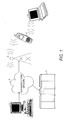
- FIG. 1 is an illustration of an exemplary communications system
- a remote terminal 1 and a server 2 are shown connected via a communications network 3 and a radio link 4 to a mobile phone 5.
- a portable computer 6 is also illustrated arranged to communicate with the radio link 4 via the mobile phone 5.
- a conventional mobile phone 5 is able to communicate in a number of different ways, for example through the transmission of radio signals or alternatively through the transmission of infrared signals, the conventional computer architecture for a mobile phone 5 restricts the possible functionality of the mobile phone 5.
- a remote terminal 1 it is possible to store programs in the memory of a phone 5 which enables the phone 5 to generate appropriate radio signals for, for example, requesting data from a remote terminal 1 or a server 2 or alternatively for generating infra red signals for transmitting instructions to a television or other infrared activated device, it is not possible for a remote terminal 1 to activate the mobile phone 5 remotely to program a television or video.
- a mobile phone 5 can act as a conduit for passing signals between a radio link 4 and a portable computer 6, the role of the mobile phone 5 in such an arrangement is limited to the conversion of radio signals into infrared signals and vice versa. In such conventional systems, it is not possible to utilise the processing power available on a modern mobile phone 5 to alter the signals during their passage.
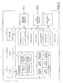
- a mobile phone 5 comprises a microphone 13, a speaker 14, an infrared detector/emitter 15, a radio transmitter/receiver 17, a memory 19 and a processing unit 20.
- the memory 19 is configured to store computer instructions for causing the processing unit 20 to process signals received from the keypad 10 and microphone 13, the infrared detector/emitter 15 and the radio transmitter/receiver 17 in a variety of different ways and to output signals to the display screen 11, the speaker 14, the infrared detector/emitter 15 and the radio transmitter/receiver 17.
- the memory 19 is shown storing a series of functional modules. These modules comprise a micro-server module 21, a set of adaptor modules 22-28 for converting signals between a number of different formats and a set of processing modules 30-38 for controlling different functions of the phone 5. As will be described in greater detail, the micro-sever module 21 is arranged to co-ordinate the routing of signals between the other modules 22-38.
- the micro-server 21 is arranged to store data associating text strings identifying commands and data sources with routing destinations.
- the micro-server 21 When a signal is received by the micro-server 21 from any of the adaptor modules 22 - 28 or any of the processing modules 30 - 38, the micro-server 21 initially the micro-server 21 checks whether the received signal includes a text string corresponding command. If this is the case, the micro-server 21 routes the signal to the location associated with that command. Otherwise the micro-server 21 routes the signal on the basis of the identity of the module 22-38 from which the signal was received.
- Providing a micro-server 21 and a set of adaptor modules 22-28 in this way increases the functionality of the mobile phone 5. This is because having a separate micro-server 21 separates the function of deciding where a signal is to be routed from the process of converting external signals into a format which can be understood by the functional modules 30-38 of the phone 5.
- the adaptors 22-28 enable all signals which need to be processed by the micro-server 21 to be in a common format.
- the micro-server 21 therefore does not need to distinguish between internally generated signals such as those received from the keypad 10 or microphone 13 or the processing modules 30-38 and the signals generated by the adaptor modules 22-28. Thus potentially any signal from any source can be utilised to access any of the stored processing modules 30-38.
- the adaptor modules comprise an infra red adaptor 22 for processing infra red signals, a blue tooth adaptor 24 for processing blue tooth signals, an HTTP adaptor 25 for processing HTTP signals, an SMS adaptor 26 for processing SMS signals, a voice adaptor 27 for processing voice signals and a GPS adaptor 28 for processing GPS signals.
- the adaptors 22-28 are also arranged to receive signals from the micro-server 21 and to convert the signals into an appropriate format for activating the infra red detector/emitter 15 or the radio transmitter/receiver 17 respectively.
- the processing modules 30-38 comprise a control module 30 for enabling the phone to switch between different functions, a phone module 32 for controlling the phone when sending and receiving voice messages, a browser module 34 for controlling the operations of the phone 5 when accessing a server 2 or remote computer 1, an SMS module 35 for enabling the phone 5 to send and receive SMS messages, a GPS module 36 for processing GPS signals and a TV remote module 38 for enabling the phone to operate as a universal remote control.
- the micro-server 21 in this embodiment, comprises a routing module 40 and three lookup tables 42-46, being a standard routing table 42 storing data identifying the normal routing locations associated with different modules and commands, a dynamic routing table 44 for storing temporary routing instruction for specific actions being undertaken by the mobile phone 5 and a permission database 46 identifying which external computers 1,2,6 are permitted to instruct particular processing modules 32-38 stored within the memory 19.
- routing data stored in the standard routing table 42 Signals From Route To Keypad Control Module Microphone Phone Module Voice Adaptor Phone Module GPS Adaptor GPS Module
- the standard routing table 42 also stores data identifying a series of text strings associated with commands together with data identifying different processing modules or adaptors associated with processing those commands such as the following: Command Route To Transmit as HTTP HTTP Adaptor Activate TV Remote TV Remote Output Location GPS Module Activate Key Pad - - - - - - - - -
- the permission database 46 stores data identifying the external computers from which such instructions may be received, such as: Command Permitted Activate TV Remote Remote Terminal 1 Output Location Remote Terminal 1
- FIGs 3A & B which together are a flow diagram of the processing of signals by the mobile phone 5 of Figure 2, initially the phone 5 waits (S3-1) until a signal is received by either the infra red detector/emitter 15 or the radio transmitter/receiver 17 or from the keypad 10 or microphone 13. The phone 5 then determines (S3-2) whether the signal is an internal signal received from the keypad 10 or microphone 13 or an external signal received by the infra red detector/emitter 15 or the radio transmitter 17.
- the signal is sent to an adaptor module 22-28 for conversion.
- the signal is immediately passed to the infra red adaptor 22 for conversion (s3-4).
- the radio transmitter/receiver 17 selects (s3-5) an appropriate adaptor 24-28 for converting the received signal on the basis of the frequency of the received radio signal.
- the selected adaptor then proceeds to convert the received signal into a native code signal which is suitable for processing by the micro-server 21.
- the signals received by the micro-server 21 will each comprise a conventional signal or alternatively comprise a signal in a format which will be recognised by the micro-server 21 as representing a command.
- Figure 4 is a schematic block diagram of a data structure of a signal generated by the adaptors 22-28 for a command.
- a signal comprises a command data 50 being a text string identifying a command and optionally attribute data 51, a sender address 52 and one or more response addresses 53.
- a command could be in the form of: COMMAND DATA TRANSMIT AS HTTP ATTRIBUTE DATA HTTP DATA TO BE DISPATCHED SENDER ADDRESS DATA ID FOR PORTABLE COMPUTER 6 RESPONSE ADDRESS DATA NONE
- the routing module 40 then proceeds to determine where the received signal should be routed.
- the routing module 40 initially checks (s3-6) the received signal to determine whether or not the received signal includes command data 50.
- the routing module 40 then checks (s3-7) the dynamic routing table 44 to see if any routing data relating to signals from the module from which the signal was received has been stored. If this is the case, the routing module dispatches (s3-8) the signal to the location identified by the dynamic routing table 44. Otherwise, the routing module 40 dispatches (s3-8) the signal to a location based upon the location associated with the origin of the signal by an entry in the standard routing table 42.
- routing module 40 determines (s3-6) a received signal relates to a command, initially the routing module 40 checks (s3-10) that remote activation is permitted for that command. In this embodiment, this is achieved by the routing module 40 either determining that no entry associated with the command is stored in the permission database 46 or alternatively data corresponding to the sender address 52 received with the command is stored in association with data identifying the received command.
- the routing module 40 then checks (s3-7) the dynamic routing table 44 to see if any routing data relating to the identified command included in the signal has been stored. If this is the case, the routing module dispatches (s3-8) the signal to the location identified by the dynamic routing table 44. Otherwise, the routing module 40 dispatches (s3-8) the signal to a location based upon the location associated with the identified command included in the signal by an entry in the standard routing table 42.
- the routing module 40 also updates the content of the dynamic routing table 42. This is achieved by the routing module 40 determining whether a command includes a response address 53. If this is the case the routing module 40 stores an entry in the dynamic routing table 44 link the module or adaptor to which data has just been dispatched to the identified response address.
- the routing module 40 when processing the following command received from the HTTP adaptor 26: COMMAND OUTPUT LOCATION ATTRIBUTES REMOTE TERMINAL ADDRESS SENDER ADDRESS REMOTE TERMINAL 1 RESPONSE ADDRESS HTTP ADAPTOR the routing module 40 would initially check the permission database 46 to establish whether remote terminal 1 was permitted to use the command "Output Location". If this was found to be the case, the command "Output Location" together with attribute data identifying the remote terminal address would be dispatched to the location associated with that command either by an entry in the dynamic routing table 44 or if no entry for that command appeared in the dynamic routing table 44 the standard routing table 42. Finally the dynamic routing table 44 would be updated so that any responses sent by the module associated with the "Output Location" command would be routed to the HTTP adaptor 26.
- routing module 40 determines (s3-11) that a received signal is to be processed by one of the processing modules 30-38, the identified module 30-38 is activated and the signal passed to the selected module and processed (S3-12).
- this signal will also be of the same form as a signal generated by one of the adaptor modules 22-28. If such a signal is generated, the selected module sends the signal to the micro-server 21 where the received signal is processed in exactly the same way as if it had been received from one of the adaptors 22-28 (S3-6- S3-11).
- the routing module 40 will instead determine that the signal needs to be output (s3-14) either to the screen 11 or speaker 14 or to one of the adaptor modules 22-28.
- the routed signal is then output as either sound through the speaker 14 or an image on the screen 11.
- the identified adaptor proceeds to process the received signal and converts it into the format associated with that adaptor.
- the converted signal is then passed to either the infra red detector/emitter 15 or the radio transmitter/receiver 17 which generates and outputs either an infra red signal or a radio signal corresponding to the converted signal in a conventional manner.
- Example 1 Use of mobile phone 5 as remote control
- the micro-server 21 then proceeds to update the dynamic routing table 44 to store data in the dynamic routing table 44 linking the keypad 10 and the TV remote module 38 so that all responses received by the micro-server 21 from the keypad 10 are then routed to the TV remote module 38.
- the micro-server 21 then proceeds to check the dynamic routing table 44 and routes the signal to the location associated with responses from the keypad 10 by the dynamic routing database 44. In the present case, where data identifying the TV remote module 38 is stored in the dynamic routing table 44 this will cause the signal to be routed from the keypad 10 via the micro-server 21 to the TV remote module 38.
- the TV remote module 38 In response to receiving these signals, the TV remote module 38 then generates a command of the following form: COMMAND TRANSMIT TO IR ADAPTOR ATTRIBUTES DATA REPRESENTING KEY PRESS SENDER ADDRESS TV REMOTE MODULE RESPONSE ADDRESS NONE
- the micro-server 21 In response to receiving such a signal from the TV remote module 38, as the signal includes command data 50, the micro-server 21 initially checks the permission database 46 to confirm that the TV remote module 38 is permitted to send data to the IR adaptor. The micro-server 21 then checks the dynamic routing table 42 and then the standard routing table 44 to identify which location is associated with the "Transmit to IR Adaptor" command. This will identify the infra red adaptor 22.
- the micro-server 21 then routes the received attribute data to the infra red adaptor 22 which converts the received data into a signal for activating the infra red detector/emitter 15 and an infra red signal representing the key press is then output by the infra red detector/emitter 15.
- a remote controlled device such as a TV or video
- the remote device will then respond to the received infra red signal in a conventional manner.
- Example 2 Transmission of data between a portable computer 6 and a radio link 4
- the portable computer 6 When an http message is to be sent from a portable computer 6 to a remote terminal 1 or a server 2 via a mobile phone 5 and a radio link, initially, the portable computer 6 generates and infra red signal encoding a signal of the following form: COMMAND TRANSMIT AS HTTP ATTRIBUTES DATA REPRESENTING MESSAGE SENDER ADDRESS PORTABLE COMPUTER RESPONSE ADDRESS IR ADAPTOR
- the infrared detector/emitter 15 When this signal is received by the infrared detector/emitter 15 it is converted into a digital signal and passed to the infra red adaptor 22 which then converts the digital signal into the format which can be understood by the micro-server 21.
- the converted signal is then processed by the micro-server 21.
- the routing module 40 checks the permission database 44 to see if the command "Transmit as HTTP" command is restricted. Assuming that this is not the case, the routing module 40 then accesses the dynamic routing table 44 and then the standard routing table 42 to identify the location to send data associated with a "Transmit as HTTP" command 50. This would then identify the HTTP adaptor 26.
- the routing module 40 then sends the data representing the message to the HTTP adaptor 26 which converts the data into a format for transmission by the radio transmitter/receiver 17 and a radio signal corresponding to the converted data is then output to the radio link 4 via the radio transmitter/receiver 17.
- the routing module 40 then causes the dynamic routing table 44 to be updated by storing data causing any responses subsequently received by the HTTP 26 adaptor to be routed to the IR adaptor 22.
- this response When a response is generated by the remote terminal 1 or server 2 with which the portable computer 6 is communicating, this response will be in the form of a radio signal encoding a conventional http message.
- the signal received by the radio transmitter/receiver 17 is converted into a digital signal and then converted into format which is understood by the micro-server 21 by the HTTP adaptor 26.
- This converted signal is then passed to the micro-server 21.
- the micro-server 21 will identify the message as being a response as the message does not include any command data. The micro-server 21 therefore routes the response based upon the identification of the module from which the signal was received.
- the routing module 40 would check the dynamic routing table 44 and establish that as the signal was received from the HTTP adaptor 25, it should be routed to the infra red adaptor 22.
- the data representing a received response is therefore sent to the infra red adaptor 22 which converts the data into an infra red signal which is then output by the infra red detector/emitter 15 to the portable computer 6.
- a remote terminal 1 is utilised to try to obtain information about the current location of a mobile phone 5.
- Such a system might be of interest to a company which was attempting to track the locations of its vehicles.
- the routing module When such an instruction was received by the micro-server 21, the routing module would initially check that remote terminal 1 was permitted to use the "Output Location” command by checking the permission database 46. When this had been confirmed, the instruction "Output Location” command and the attribute data would be sent to the GPS module 36 on the basis of an entry stored in the standard routing database 42 identifying that the command "Output Location” should be routed to the GPS module 36.
- routing module 40 would generate an entry in the dynamic routing table 44 to cause a generated response by the GPS module 36 to be routed back to the HTTP adaptor 25.
- the GPS Module 36 In response to receiving the 'Output Location' command, the GPS Module 36 would then output location data based upon the latest GPS signal output by the GPS adaptor 28 routed to the GPS module 28 by the micro-server 21 together with data identifying the remote terminal address. This response would then be sent to the micro-server 21 which would then proceed to route the response to the HTTP adaptor 25.
- the signal incorporating the position data and remote terminal address When this response was received by the HTTP adaptor 25, the signal incorporating the position data and remote terminal address would be converted into a radio signal and sent to the terminal identified by the remote terminal address via the radio link 4 and the communications network 3.
- the dynamic routing table 44 would have stored the following entries to cause the signals from the keypad 10 and HTTP adaptor 25 to be sent to the browser module 34 for processing and to send the output of the browser module 34 to the http adaptor 25 for dispatch to the server 2.
- the server 2 When accessing a particular link on a webpage for enabling a user to send feedback, the server 2 might, having identified that a user was browsing using a mobile phone 5, send the following instruction: COMMAND SEND SMS MESSAGE ATTRIBUTES TELEPHONE NUMBER SENDER ADDRESS SERVER 2 RESPONSE ADDRESS NONE
- the micro-server 21 When such an instruction was received by the micro-server 21 via the http adaptor 25, as the instruction is in the form of a command rather than merely a response from the server 2, when the signal is processed by the micro-server 21 rather than being routed to the browser module 34, the micro-server 21 would initially check the permission database 46 to determine whether use of the "Send SMS Message" was permitted by the server 2. If this was the case the command and attribute data would then be sent to the SMS module 35, being the module associated with the "Send SMS Message" command by data in the standard routing table 42.
- the instruction When received by the SMS module 35, the instruction would then be processed which would initially store the received telephone number and then cause a command to be sent to the micro-server 21 in the following form to enable a user to enter a text message COMMAND ACTIVATE KEYPAD ATTRIBUTES NONE SENDER ADDRESS SMS MODULE RESPONSE ADDRESS SMS MODULE
- the routing module would cause the signals generated as a result of pressing the button on the keypad 10 to be sent to the SMS module 34 so that a user could enter a text message.
- SMS module 34 When the send button was the pressed, the SMS module 34 would then generate a command of the following form to cause in SMS message to be sent to the telephone number received from the server 2: COMMAND TRANSMIT AS SMS ATTRIBUTES TELEPHONE NUMBER & MESSAGE SENDER ADDRESS SMS MODULE RESPONSE ADDRESS NONE
- the micro-server 21 Upon receiving this signal, the micro-server 21 would then route the telephone number and message to the SMS adaptor 26, being the routing destination associated with the "Transmit as SMS" command. This signal would then be processed by the SMS adaptor 26 before being send to the radio transmitter/receiver 17 so as to output a radio signal encoding the message for forwarding to the receiver identified by the telephone number.
- command data is described as being a text string identifying a command.
- the text string could be of a number of different forms.
- a prefix of a text string could indicate that a string identified a command and the rest of the text string might indicate the specific command to be performed.
- a string might be of the form: www.localhost ⁇ dialnumber ⁇ where www.localhost ⁇ " was a prefix indicating that a string represents a command and " dialnumber ⁇ " indicates the specific instruction to be performed.
- the prefix would be utilised by the routing module 40 to identify that a string constituted a command and the rest of the string would be used to select an appropriate module for executing the command.
- the fact a string was a command could be indicated in other ways, for example by sending type data indicting a type command rather than including a common prefix in the command strings.
- a permission database 46 which is utilised to determine which external computers are permitted to initiate certain actions within a mobile phone 5. It will be appreciated that rather than the data in a permission database 46 identifying individual computers the data could identify groups of computers permitted to access certain commands. Thus for example data might indicate that all computers having a network address starting with certain values are permitted to utilise a particular command.
- a permission database 46 could be provided which stored more complex rules for determining whether or not a particular computer is allowed to initiate certain instructions within a remote device.
- the embodiments of the invention described with reference to the drawings comprise computer apparatus and processes performed in computer apparatus, the invention also extends to computer programs, particularly computer programs on or in a carrier, adapted for putting the invention into practice.
- the program may be in the form of source or object code or in any other form suitable for use in the implementation of the processes according to the invention.
- the carrier can be any entity or device capable of carrying the program.
- the carrier may comprise a storage medium, such as a ROM, for example a CD ROM or a semiconductor ROM, or a magnetic recording medium, for example a floppy disc or hard disk.
- a storage medium such as a ROM, for example a CD ROM or a semiconductor ROM, or a magnetic recording medium, for example a floppy disc or hard disk.
- the carrier may be a transmissible carrier such as an electrical or optical signal which may be conveyed via electrical or optical cable or by radio or other means.
- the carrier When a program is embodied in a signal which may be conveyed directly by a cable or other device or means, the carrier may be constituted by such cable or other device or means.
- the carrier may be an integrated circuit in which the program is embedded, the integrated circuit being adapted for performing, or for use in the performance of, the relevant processes.
Applications Claiming Priority (2)
| Application Number | Priority Date | Filing Date | Title |
|---|---|---|---|
| GB0402252 | 2004-02-02 | ||
| GB0402252A GB2410578B (en) | 2004-02-02 | 2004-02-02 | Routing system |
Publications (2)
| Publication Number | Publication Date |
|---|---|
| EP1560116A2 true EP1560116A2 (de) | 2005-08-03 |
| EP1560116A3 EP1560116A3 (de) | 2011-07-06 |
Family
ID=31971885
Family Applications (1)
| Application Number | Title | Priority Date | Filing Date |
|---|---|---|---|
| EP05250509A Withdrawn EP1560116A3 (de) | 2004-02-02 | 2005-01-31 | Wegwahlsystem zur Weiterleitung von Daten und Befehlen in einem Mobiltelefon |
Country Status (4)
| Country | Link |
|---|---|
| US (1) | US7818451B2 (de) |
| EP (1) | EP1560116A3 (de) |
| AU (1) | AU2005200396B2 (de) |
| GB (1) | GB2410578B (de) |
Families Citing this family (4)
| Publication number | Priority date | Publication date | Assignee | Title |
|---|---|---|---|---|
| GB0021988D0 (en) * | 2000-09-07 | 2000-10-25 | Nokia Mobile Phones Ltd | Management of portable radiotelephones |
| US10290055B2 (en) * | 2006-04-21 | 2019-05-14 | Refinitiv Us Organization Llc | Encoded short message service text messaging systems and methods |
| CN102656842B (zh) * | 2009-12-09 | 2016-09-07 | 汤姆森特许公司 | 基于网络的远程电力管理 |
| US11157298B2 (en) * | 2019-05-21 | 2021-10-26 | Salesforce.Com, Inc. | Method and system for automatically invoking functionality while using a primary application without user action |
Citations (5)
| Publication number | Priority date | Publication date | Assignee | Title |
|---|---|---|---|---|
| WO2000060455A2 (en) * | 1999-04-02 | 2000-10-12 | Powerware Corporation | Systems, methods and computer program products for event and action management in data processing systems using event handler intermediaries |
| US6398105B2 (en) * | 1999-01-29 | 2002-06-04 | Intermec Ip Corporation | Automatic data collection device that intelligently switches data based on data type |
| US20030088672A1 (en) * | 2001-10-29 | 2003-05-08 | Shinobu Togasaki | Apparatus and method for routing a transaction to a server |
| US6668284B1 (en) * | 1998-11-04 | 2003-12-23 | Beckman Coulter, Inc. | Software messaging system |
| US20040019893A1 (en) * | 2002-07-29 | 2004-01-29 | Hepworth Paul J. | Systems and methods for interfacing multiple types of object identifiers and object identifier readers to multiple types of applications |
Family Cites Families (25)
| Publication number | Priority date | Publication date | Assignee | Title |
|---|---|---|---|---|
| US4937862A (en) * | 1988-10-14 | 1990-06-26 | Enforcement Support Incorporated | Remote monitoring device |
| WO1993010617A1 (en) * | 1991-11-12 | 1993-05-27 | Fisk Communications, Inc. | Stand-alone device to transfer computer files using a communication line shared by a facsimile machine |
| US5568614A (en) * | 1994-07-29 | 1996-10-22 | International Business Machines Corporation | Data streaming between peer subsystems of a computer system |
| US6424992B2 (en) * | 1996-12-23 | 2002-07-23 | International Business Machines Corporation | Affinity-based router and routing method |
| US5937168A (en) * | 1997-05-30 | 1999-08-10 | Bellsouth Corporation | Routing information within an adaptive routing architecture of an information retrieval system |
| US6119165A (en) * | 1997-11-17 | 2000-09-12 | Trend Micro, Inc. | Controlled distribution of application programs in a computer network |
| US6247086B1 (en) * | 1998-11-12 | 2001-06-12 | Adaptec, Inc. | PCI bridge for optimized command delivery |
| US6697942B1 (en) * | 1999-02-04 | 2004-02-24 | Earthlink, Inc. | Method for remotely managing a remote device using an electronic mail message |
| US6370605B1 (en) * | 1999-03-04 | 2002-04-09 | Sun Microsystems, Inc. | Switch based scalable performance storage architecture |
| US7505759B1 (en) * | 1999-06-21 | 2009-03-17 | Alcatel-Lucent Usa Inc. | System for message control and redirection in a wireless communications network |
| US6678371B1 (en) * | 2000-02-15 | 2004-01-13 | Avaya Technolocy Corp. | Direct customer control of a network router |
| AU2001222161A1 (en) * | 2000-07-28 | 2002-02-13 | Delvalley Limited | A data processor |
| US7035202B2 (en) * | 2001-03-16 | 2006-04-25 | Juniper Networks, Inc. | Network routing using link failure information |
| CN1219361C (zh) * | 2001-03-28 | 2005-09-14 | 国际商业机器公司 | 用于红外接口的蓝牙适配器及相关的通信方法 |
| US20020157113A1 (en) * | 2001-04-20 | 2002-10-24 | Fred Allegrezza | System and method for retrieving and storing multimedia data |
| US7051367B1 (en) * | 2001-05-14 | 2006-05-23 | Juniper Networks, Inc. | Dynamically controlling packet processing |
| US7426573B2 (en) * | 2001-12-12 | 2008-09-16 | Alcatel Lucent | System and method for providing service availability data for a communication network |
| US7127261B2 (en) * | 2002-02-22 | 2006-10-24 | Julian Van Erlach | Enhanced telecommunication services |
| US7603449B1 (en) * | 2002-06-10 | 2009-10-13 | Crossroads Systems, Inc. | System and method for inquiry caching |
| US7336973B2 (en) * | 2002-10-30 | 2008-02-26 | Way Systems, Inc | Mobile communication device equipped with a magnetic stripe reader |
| US7233975B1 (en) * | 2002-08-19 | 2007-06-19 | Juniper Networks, Inc. | Private configuration of network devices |
| US7353321B2 (en) * | 2003-01-13 | 2008-04-01 | Sierra Logic | Integrated-circuit implementation of a storage-shelf router and a path controller card for combined use in high-availability mass-storage-device shelves that may be incorporated within disk arrays |
| DE10301265A1 (de) * | 2003-01-15 | 2004-07-29 | Siemens Ag | Verfahren und Anordnung zum Routing von Datenpaketen in einem paketvermittelnden Datennetz |
| US7188121B2 (en) * | 2003-02-06 | 2007-03-06 | Sun Microsystems, Inc. | Information system management |
| US7313629B1 (en) * | 2003-11-06 | 2007-12-25 | Sprint Communications Company L.P. | Method for altering link weights in a communication network within network parameters to provide traffic information for improved forecasting |
-
2004
- 2004-02-02 GB GB0402252A patent/GB2410578B/en not_active Expired - Lifetime
- 2004-11-30 US US11/000,200 patent/US7818451B2/en active Active
-
2005
- 2005-01-31 EP EP05250509A patent/EP1560116A3/de not_active Withdrawn
- 2005-02-01 AU AU2005200396A patent/AU2005200396B2/en active Active
Patent Citations (5)
| Publication number | Priority date | Publication date | Assignee | Title |
|---|---|---|---|---|
| US6668284B1 (en) * | 1998-11-04 | 2003-12-23 | Beckman Coulter, Inc. | Software messaging system |
| US6398105B2 (en) * | 1999-01-29 | 2002-06-04 | Intermec Ip Corporation | Automatic data collection device that intelligently switches data based on data type |
| WO2000060455A2 (en) * | 1999-04-02 | 2000-10-12 | Powerware Corporation | Systems, methods and computer program products for event and action management in data processing systems using event handler intermediaries |
| US20030088672A1 (en) * | 2001-10-29 | 2003-05-08 | Shinobu Togasaki | Apparatus and method for routing a transaction to a server |
| US20040019893A1 (en) * | 2002-07-29 | 2004-01-29 | Hepworth Paul J. | Systems and methods for interfacing multiple types of object identifiers and object identifier readers to multiple types of applications |
Also Published As
| Publication number | Publication date |
|---|---|
| GB2410578B (en) | 2008-04-16 |
| US20050169240A1 (en) | 2005-08-04 |
| GB2410578A (en) | 2005-08-03 |
| AU2005200396B2 (en) | 2009-07-02 |
| AU2005200396A1 (en) | 2005-08-18 |
| GB0402252D0 (en) | 2004-03-03 |
| EP1560116A3 (de) | 2011-07-06 |
| US7818451B2 (en) | 2010-10-19 |
Similar Documents
| Publication | Publication Date | Title |
|---|---|---|
| US7239891B2 (en) | Portable telecommunication apparatus for controlling an electronic utility device | |
| US20050102625A1 (en) | Audio tag retrieval system and method | |
| US8417768B2 (en) | Communication terminal communicating via communication network | |
| US8069222B2 (en) | System and method to provide services based on network | |
| JP2012518309A (ja) | メッセージ処理装置及び方法 | |
| US7486970B2 (en) | Mobile terminal and system for providing total status information thereof at one time | |
| CN101019404A (zh) | 用于从多个源无线下载媒体对象的能力的系统和方法 | |
| JPWO2005096165A1 (ja) | ポータルシステム | |
| AU2005200396B2 (en) | Routing System | |
| WO2004060003A1 (en) | Method for presenting location information on a mobile terminal | |
| JP2006211471A (ja) | 無線通信システム、通信端末 | |
| JP2002297474A (ja) | 電子掲示板システム、遠隔端末、及びプログラム | |
| JP4462159B2 (ja) | 電話装置 | |
| EP1635267A1 (de) | Dienstausnutzungsendgerät, das benutzern in einem netzwerk bereitgestellte funktionen bereitstellt | |
| KR100538646B1 (ko) | 이동통신단말기로의 메시지 코디 전송방법 및 그 시스템 | |
| KR100635092B1 (ko) | 모바일용 홈페이지 변환 시스템 및 방법 | |
| WO2005101801A1 (ja) | 通信機器およびプログラム実行方法 | |
| KR100706348B1 (ko) | 이동통신 단말기를 이용한 위치기반 주변정보 제공 시스템및 방법 | |
| JPH11136275A (ja) | 情報通信方法、情報通信システム、サーバ装置および携帯情報通信端末 | |
| KR100642577B1 (ko) | 음성 메시지를 문자 메시지로 변환하여 전송하는 방법 및장치 | |
| KR100559140B1 (ko) | 멀티미디어 메시지 전송 방법 및 시스템 | |
| KR100644897B1 (ko) | 이동 통신 단말기에서 근거리 통신을 이용하여 데이터를송수신하는 방법 | |
| KR100793424B1 (ko) | 간편 접속 무선 인터넷 서비스 제공 방법 및 장치 | |
| KR101047500B1 (ko) | 이동통신 시스템 및 그의 부가서비스 제공방법 | |
| KR100631697B1 (ko) | 휴대단말기 및 휴대단말기의 아이디 운용방법 |
Legal Events
| Date | Code | Title | Description |
|---|---|---|---|
| PUAI | Public reference made under article 153(3) epc to a published international application that has entered the european phase |
Free format text: ORIGINAL CODE: 0009012 |
|
| 17P | Request for examination filed |
Effective date: 20050211 |
|
| AK | Designated contracting states |
Kind code of ref document: A2 Designated state(s): AT BE BG CH CY CZ DE DK EE ES FI FR GB GR HU IE IS IT LI LT LU MC NL PL PT RO SE SI SK TR |
|
| AX | Request for extension of the european patent |
Extension state: AL BA HR LV MK YU |
|
| RAP1 | Party data changed (applicant data changed or rights of an application transferred) |
Owner name: SURFKITCHEN LIMITED |
|
| PUAL | Search report despatched |
Free format text: ORIGINAL CODE: 0009013 |
|
| AK | Designated contracting states |
Kind code of ref document: A3 Designated state(s): AT BE BG CH CY CZ DE DK EE ES FI FR GB GR HU IE IS IT LI LT LU MC NL PL PT RO SE SI SK TR |
|
| AX | Request for extension of the european patent |
Extension state: AL BA HR LV MK YU |
|
| STAA | Information on the status of an ep patent application or granted ep patent |
Free format text: STATUS: THE APPLICATION HAS BEEN WITHDRAWN |
|
| AKX | Designation fees paid |
Designated state(s): AT BE BG CH CY CZ DE DK EE ES FI FR GB GR HU IE IS IT LI LT LU MC NL PL PT RO SE SI SK TR |
|
| 18W | Application withdrawn |
Effective date: 20120213 |