EP1559622B1 - Vehicle passenger protecting apparatus - Google Patents
Vehicle passenger protecting apparatus Download PDFInfo
- Publication number
- EP1559622B1 EP1559622B1 EP05001737.5A EP05001737A EP1559622B1 EP 1559622 B1 EP1559622 B1 EP 1559622B1 EP 05001737 A EP05001737 A EP 05001737A EP 1559622 B1 EP1559622 B1 EP 1559622B1
- Authority
- EP
- European Patent Office
- Prior art keywords
- vehicle
- passenger
- state
- air bag
- collision
- Prior art date
- Legal status (The legal status is an assumption and is not a legal conclusion. Google has not performed a legal analysis and makes no representation as to the accuracy of the status listed.)
- Expired - Fee Related
Links
Images


Classifications
-
- B—PERFORMING OPERATIONS; TRANSPORTING
- B60—VEHICLES IN GENERAL
- B60N—SEATS SPECIALLY ADAPTED FOR VEHICLES; VEHICLE PASSENGER ACCOMMODATION NOT OTHERWISE PROVIDED FOR
- B60N2/00—Seats specially adapted for vehicles; Arrangement or mounting of seats in vehicles
- B60N2/90—Details or parts not otherwise provided for
- B60N2/986—Side-rests
- B60N2/99—Side-rests adjustable
-
- B—PERFORMING OPERATIONS; TRANSPORTING
- B60—VEHICLES IN GENERAL
- B60N—SEATS SPECIALLY ADAPTED FOR VEHICLES; VEHICLE PASSENGER ACCOMMODATION NOT OTHERWISE PROVIDED FOR
- B60N2/00—Seats specially adapted for vehicles; Arrangement or mounting of seats in vehicles
- B60N2/24—Seats specially adapted for vehicles; Arrangement or mounting of seats in vehicles for particular purposes or particular vehicles
- B60N2/42—Seats specially adapted for vehicles; Arrangement or mounting of seats in vehicles for particular purposes or particular vehicles the seat constructed to protect the occupant from the effect of abnormal g-forces, e.g. crash or safety seats
- B60N2/427—Seats or parts thereof displaced during a crash
- B60N2/42772—Seats or parts thereof displaced during a crash characterised by the triggering system
- B60N2/4279—Seats or parts thereof displaced during a crash characterised by the triggering system electric or electronic triggering
-
- B—PERFORMING OPERATIONS; TRANSPORTING
- B60—VEHICLES IN GENERAL
- B60N—SEATS SPECIALLY ADAPTED FOR VEHICLES; VEHICLE PASSENGER ACCOMMODATION NOT OTHERWISE PROVIDED FOR
- B60N2/00—Seats specially adapted for vehicles; Arrangement or mounting of seats in vehicles
- B60N2/90—Details or parts not otherwise provided for
- B60N2/986—Side-rests
-
- B—PERFORMING OPERATIONS; TRANSPORTING
- B60—VEHICLES IN GENERAL
- B60R—VEHICLES, VEHICLE FITTINGS, OR VEHICLE PARTS, NOT OTHERWISE PROVIDED FOR
- B60R21/00—Arrangements or fittings on vehicles for protecting or preventing injuries to occupants or pedestrians in case of accidents or other traffic risks
- B60R21/01—Electrical circuits for triggering passive safety arrangements, e.g. airbags, safety belt tighteners, in case of vehicle accidents or impending vehicle accidents
- B60R21/013—Electrical circuits for triggering passive safety arrangements, e.g. airbags, safety belt tighteners, in case of vehicle accidents or impending vehicle accidents including means for detecting collisions, impending collisions or roll-over
-
- B—PERFORMING OPERATIONS; TRANSPORTING
- B60—VEHICLES IN GENERAL
- B60R—VEHICLES, VEHICLE FITTINGS, OR VEHICLE PARTS, NOT OTHERWISE PROVIDED FOR
- B60R21/00—Arrangements or fittings on vehicles for protecting or preventing injuries to occupants or pedestrians in case of accidents or other traffic risks
- B60R21/02—Occupant safety arrangements or fittings, e.g. crash pads
- B60R21/16—Inflatable occupant restraints or confinements designed to inflate upon impact or impending impact, e.g. air bags
- B60R21/20—Arrangements for storing inflatable members in their non-use or deflated condition; Arrangement or mounting of air bag modules or components
- B60R21/207—Arrangements for storing inflatable members in their non-use or deflated condition; Arrangement or mounting of air bag modules or components in vehicle seats
-
- B—PERFORMING OPERATIONS; TRANSPORTING
- B60—VEHICLES IN GENERAL
- B60R—VEHICLES, VEHICLE FITTINGS, OR VEHICLE PARTS, NOT OTHERWISE PROVIDED FOR
- B60R21/00—Arrangements or fittings on vehicles for protecting or preventing injuries to occupants or pedestrians in case of accidents or other traffic risks
- B60R21/02—Occupant safety arrangements or fittings, e.g. crash pads
- B60R21/16—Inflatable occupant restraints or confinements designed to inflate upon impact or impending impact, e.g. air bags
- B60R21/20—Arrangements for storing inflatable members in their non-use or deflated condition; Arrangement or mounting of air bag modules or components
- B60R21/215—Arrangements for storing inflatable members in their non-use or deflated condition; Arrangement or mounting of air bag modules or components characterised by the covers for the inflatable member
- B60R21/216—Arrangements for storing inflatable members in their non-use or deflated condition; Arrangement or mounting of air bag modules or components characterised by the covers for the inflatable member comprising tether means for limitation of cover motion during deployment
-
- B—PERFORMING OPERATIONS; TRANSPORTING
- B60—VEHICLES IN GENERAL
- B60R—VEHICLES, VEHICLE FITTINGS, OR VEHICLE PARTS, NOT OTHERWISE PROVIDED FOR
- B60R21/00—Arrangements or fittings on vehicles for protecting or preventing injuries to occupants or pedestrians in case of accidents or other traffic risks
- B60R21/02—Occupant safety arrangements or fittings, e.g. crash pads
- B60R21/16—Inflatable occupant restraints or confinements designed to inflate upon impact or impending impact, e.g. air bags
- B60R21/23—Inflatable members
- B60R21/237—Inflatable members characterised by the way they are folded
-
- B—PERFORMING OPERATIONS; TRANSPORTING
- B60—VEHICLES IN GENERAL
- B60R—VEHICLES, VEHICLE FITTINGS, OR VEHICLE PARTS, NOT OTHERWISE PROVIDED FOR
- B60R21/00—Arrangements or fittings on vehicles for protecting or preventing injuries to occupants or pedestrians in case of accidents or other traffic risks
- B60R21/02—Occupant safety arrangements or fittings, e.g. crash pads
- B60R21/16—Inflatable occupant restraints or confinements designed to inflate upon impact or impending impact, e.g. air bags
- B60R21/26—Inflatable occupant restraints or confinements designed to inflate upon impact or impending impact, e.g. air bags characterised by the inflation fluid source or means to control inflation fluid flow
- B60R21/268—Inflatable occupant restraints or confinements designed to inflate upon impact or impending impact, e.g. air bags characterised by the inflation fluid source or means to control inflation fluid flow using instantaneous release of stored pressurised gas
-
- B—PERFORMING OPERATIONS; TRANSPORTING
- B60—VEHICLES IN GENERAL
- B60R—VEHICLES, VEHICLE FITTINGS, OR VEHICLE PARTS, NOT OTHERWISE PROVIDED FOR
- B60R21/00—Arrangements or fittings on vehicles for protecting or preventing injuries to occupants or pedestrians in case of accidents or other traffic risks
- B60R2021/0002—Type of accident
- B60R2021/0006—Lateral collision
-
- B—PERFORMING OPERATIONS; TRANSPORTING
- B60—VEHICLES IN GENERAL
- B60R—VEHICLES, VEHICLE FITTINGS, OR VEHICLE PARTS, NOT OTHERWISE PROVIDED FOR
- B60R21/00—Arrangements or fittings on vehicles for protecting or preventing injuries to occupants or pedestrians in case of accidents or other traffic risks
- B60R21/01—Electrical circuits for triggering passive safety arrangements, e.g. airbags, safety belt tighteners, in case of vehicle accidents or impending vehicle accidents
- B60R2021/01204—Actuation parameters of safety arrangents
- B60R2021/01211—Expansion of air bags
- B60R2021/01231—Expansion of air bags control of expansion timing or sequence
-
- B—PERFORMING OPERATIONS; TRANSPORTING
- B60—VEHICLES IN GENERAL
- B60R—VEHICLES, VEHICLE FITTINGS, OR VEHICLE PARTS, NOT OTHERWISE PROVIDED FOR
- B60R21/00—Arrangements or fittings on vehicles for protecting or preventing injuries to occupants or pedestrians in case of accidents or other traffic risks
- B60R21/02—Occupant safety arrangements or fittings, e.g. crash pads
- B60R2021/0206—Self-supporting restraint systems, e.g. restraining arms, plates or the like
- B60R2021/0246—Self-supporting restraint systems, e.g. restraining arms, plates or the like mounted on side walls
-
- B—PERFORMING OPERATIONS; TRANSPORTING
- B60—VEHICLES IN GENERAL
- B60R—VEHICLES, VEHICLE FITTINGS, OR VEHICLE PARTS, NOT OTHERWISE PROVIDED FOR
- B60R21/00—Arrangements or fittings on vehicles for protecting or preventing injuries to occupants or pedestrians in case of accidents or other traffic risks
- B60R21/02—Occupant safety arrangements or fittings, e.g. crash pads
- B60R2021/0293—Additional pads or cushions in vehicle compartments, e.g. movably mounted
-
- B—PERFORMING OPERATIONS; TRANSPORTING
- B60—VEHICLES IN GENERAL
- B60R—VEHICLES, VEHICLE FITTINGS, OR VEHICLE PARTS, NOT OTHERWISE PROVIDED FOR
- B60R21/00—Arrangements or fittings on vehicles for protecting or preventing injuries to occupants or pedestrians in case of accidents or other traffic risks
- B60R21/02—Occupant safety arrangements or fittings, e.g. crash pads
- B60R21/16—Inflatable occupant restraints or confinements designed to inflate upon impact or impending impact, e.g. air bags
- B60R2021/165—Inflatable occupant restraints or confinements designed to inflate upon impact or impending impact, e.g. air bags reusable, e.g. in case of multiple collisions
-
- B—PERFORMING OPERATIONS; TRANSPORTING
- B60—VEHICLES IN GENERAL
- B60R—VEHICLES, VEHICLE FITTINGS, OR VEHICLE PARTS, NOT OTHERWISE PROVIDED FOR
- B60R21/00—Arrangements or fittings on vehicles for protecting or preventing injuries to occupants or pedestrians in case of accidents or other traffic risks
- B60R21/02—Occupant safety arrangements or fittings, e.g. crash pads
- B60R21/16—Inflatable occupant restraints or confinements designed to inflate upon impact or impending impact, e.g. air bags
- B60R21/20—Arrangements for storing inflatable members in their non-use or deflated condition; Arrangement or mounting of air bag modules or components
- B60R21/215—Arrangements for storing inflatable members in their non-use or deflated condition; Arrangement or mounting of air bag modules or components characterised by the covers for the inflatable member
- B60R2021/21525—Arrangements for storing inflatable members in their non-use or deflated condition; Arrangement or mounting of air bag modules or components characterised by the covers for the inflatable member the lid being fixed on the bag, or forming part of the bag wall, or the bag itself being used as wall liner
-
- B—PERFORMING OPERATIONS; TRANSPORTING
- B60—VEHICLES IN GENERAL
- B60R—VEHICLES, VEHICLE FITTINGS, OR VEHICLE PARTS, NOT OTHERWISE PROVIDED FOR
- B60R21/00—Arrangements or fittings on vehicles for protecting or preventing injuries to occupants or pedestrians in case of accidents or other traffic risks
- B60R21/02—Occupant safety arrangements or fittings, e.g. crash pads
- B60R21/16—Inflatable occupant restraints or confinements designed to inflate upon impact or impending impact, e.g. air bags
- B60R21/20—Arrangements for storing inflatable members in their non-use or deflated condition; Arrangement or mounting of air bag modules or components
- B60R21/215—Arrangements for storing inflatable members in their non-use or deflated condition; Arrangement or mounting of air bag modules or components characterised by the covers for the inflatable member
- B60R21/216—Arrangements for storing inflatable members in their non-use or deflated condition; Arrangement or mounting of air bag modules or components characterised by the covers for the inflatable member comprising tether means for limitation of cover motion during deployment
- B60R2021/2161—Arrangements for storing inflatable members in their non-use or deflated condition; Arrangement or mounting of air bag modules or components characterised by the covers for the inflatable member comprising tether means for limitation of cover motion during deployment the cover being displaced towards the occupant during deployment
-
- B—PERFORMING OPERATIONS; TRANSPORTING
- B60—VEHICLES IN GENERAL
- B60R—VEHICLES, VEHICLE FITTINGS, OR VEHICLE PARTS, NOT OTHERWISE PROVIDED FOR
- B60R21/00—Arrangements or fittings on vehicles for protecting or preventing injuries to occupants or pedestrians in case of accidents or other traffic risks
- B60R21/02—Occupant safety arrangements or fittings, e.g. crash pads
- B60R21/16—Inflatable occupant restraints or confinements designed to inflate upon impact or impending impact, e.g. air bags
- B60R21/20—Arrangements for storing inflatable members in their non-use or deflated condition; Arrangement or mounting of air bag modules or components
- B60R21/215—Arrangements for storing inflatable members in their non-use or deflated condition; Arrangement or mounting of air bag modules or components characterised by the covers for the inflatable member
- B60R21/216—Arrangements for storing inflatable members in their non-use or deflated condition; Arrangement or mounting of air bag modules or components characterised by the covers for the inflatable member comprising tether means for limitation of cover motion during deployment
- B60R2021/2163—Arrangements for storing inflatable members in their non-use or deflated condition; Arrangement or mounting of air bag modules or components characterised by the covers for the inflatable member comprising tether means for limitation of cover motion during deployment with energy absorbing or elastic means
-
- B—PERFORMING OPERATIONS; TRANSPORTING
- B60—VEHICLES IN GENERAL
- B60R—VEHICLES, VEHICLE FITTINGS, OR VEHICLE PARTS, NOT OTHERWISE PROVIDED FOR
- B60R21/00—Arrangements or fittings on vehicles for protecting or preventing injuries to occupants or pedestrians in case of accidents or other traffic risks
- B60R21/02—Occupant safety arrangements or fittings, e.g. crash pads
- B60R21/16—Inflatable occupant restraints or confinements designed to inflate upon impact or impending impact, e.g. air bags
- B60R21/23—Inflatable members
- B60R21/231—Inflatable members characterised by their shape, construction or spatial configuration
- B60R21/2334—Expansion control features
- B60R21/2338—Tethers
- B60R2021/23382—Internal tether means
-
- B—PERFORMING OPERATIONS; TRANSPORTING
- B60—VEHICLES IN GENERAL
- B60R—VEHICLES, VEHICLE FITTINGS, OR VEHICLE PARTS, NOT OTHERWISE PROVIDED FOR
- B60R21/00—Arrangements or fittings on vehicles for protecting or preventing injuries to occupants or pedestrians in case of accidents or other traffic risks
- B60R21/02—Occupant safety arrangements or fittings, e.g. crash pads
- B60R21/16—Inflatable occupant restraints or confinements designed to inflate upon impact or impending impact, e.g. air bags
- B60R21/23—Inflatable members
- B60R21/235—Inflatable members characterised by their material
- B60R2021/23504—Inflatable members characterised by their material characterised by material
-
- B—PERFORMING OPERATIONS; TRANSPORTING
- B60—VEHICLES IN GENERAL
- B60R—VEHICLES, VEHICLE FITTINGS, OR VEHICLE PARTS, NOT OTHERWISE PROVIDED FOR
- B60R21/00—Arrangements or fittings on vehicles for protecting or preventing injuries to occupants or pedestrians in case of accidents or other traffic risks
- B60R21/02—Occupant safety arrangements or fittings, e.g. crash pads
- B60R21/16—Inflatable occupant restraints or confinements designed to inflate upon impact or impending impact, e.g. air bags
- B60R21/26—Inflatable occupant restraints or confinements designed to inflate upon impact or impending impact, e.g. air bags characterised by the inflation fluid source or means to control inflation fluid flow
- B60R2021/26094—Inflatable occupant restraints or confinements designed to inflate upon impact or impending impact, e.g. air bags characterised by the inflation fluid source or means to control inflation fluid flow characterised by fluid flow controlling valves
-
- B—PERFORMING OPERATIONS; TRANSPORTING
- B60—VEHICLES IN GENERAL
- B60R—VEHICLES, VEHICLE FITTINGS, OR VEHICLE PARTS, NOT OTHERWISE PROVIDED FOR
- B60R21/00—Arrangements or fittings on vehicles for protecting or preventing injuries to occupants or pedestrians in case of accidents or other traffic risks
- B60R21/02—Occupant safety arrangements or fittings, e.g. crash pads
- B60R21/16—Inflatable occupant restraints or confinements designed to inflate upon impact or impending impact, e.g. air bags
- B60R21/26—Inflatable occupant restraints or confinements designed to inflate upon impact or impending impact, e.g. air bags characterised by the inflation fluid source or means to control inflation fluid flow
- B60R21/276—Inflatable occupant restraints or confinements designed to inflate upon impact or impending impact, e.g. air bags characterised by the inflation fluid source or means to control inflation fluid flow with means to vent the inflation fluid source, e.g. in case of overpressure
- B60R2021/2765—Inflatable occupant restraints or confinements designed to inflate upon impact or impending impact, e.g. air bags characterised by the inflation fluid source or means to control inflation fluid flow with means to vent the inflation fluid source, e.g. in case of overpressure comprising means to control the venting
-
- B—PERFORMING OPERATIONS; TRANSPORTING
- B60—VEHICLES IN GENERAL
- B60R—VEHICLES, VEHICLE FITTINGS, OR VEHICLE PARTS, NOT OTHERWISE PROVIDED FOR
- B60R21/00—Arrangements or fittings on vehicles for protecting or preventing injuries to occupants or pedestrians in case of accidents or other traffic risks
- B60R21/01—Electrical circuits for triggering passive safety arrangements, e.g. airbags, safety belt tighteners, in case of vehicle accidents or impending vehicle accidents
- B60R21/013—Electrical circuits for triggering passive safety arrangements, e.g. airbags, safety belt tighteners, in case of vehicle accidents or impending vehicle accidents including means for detecting collisions, impending collisions or roll-over
- B60R21/0134—Electrical circuits for triggering passive safety arrangements, e.g. airbags, safety belt tighteners, in case of vehicle accidents or impending vehicle accidents including means for detecting collisions, impending collisions or roll-over responsive to imminent contact with an obstacle, e.g. using radar systems
-
- B—PERFORMING OPERATIONS; TRANSPORTING
- B60—VEHICLES IN GENERAL
- B60R—VEHICLES, VEHICLE FITTINGS, OR VEHICLE PARTS, NOT OTHERWISE PROVIDED FOR
- B60R21/00—Arrangements or fittings on vehicles for protecting or preventing injuries to occupants or pedestrians in case of accidents or other traffic risks
- B60R21/02—Occupant safety arrangements or fittings, e.g. crash pads
- B60R21/16—Inflatable occupant restraints or confinements designed to inflate upon impact or impending impact, e.g. air bags
- B60R21/20—Arrangements for storing inflatable members in their non-use or deflated condition; Arrangement or mounting of air bag modules or components
- B60R21/21—Arrangements for storing inflatable members in their non-use or deflated condition; Arrangement or mounting of air bag modules or components in vehicle side panels, e.g. doors
-
- B—PERFORMING OPERATIONS; TRANSPORTING
- B60—VEHICLES IN GENERAL
- B60R—VEHICLES, VEHICLE FITTINGS, OR VEHICLE PARTS, NOT OTHERWISE PROVIDED FOR
- B60R21/00—Arrangements or fittings on vehicles for protecting or preventing injuries to occupants or pedestrians in case of accidents or other traffic risks
- B60R21/02—Occupant safety arrangements or fittings, e.g. crash pads
- B60R21/16—Inflatable occupant restraints or confinements designed to inflate upon impact or impending impact, e.g. air bags
- B60R21/23—Inflatable members
- B60R21/231—Inflatable members characterised by their shape, construction or spatial configuration
- B60R21/23138—Inflatable members characterised by their shape, construction or spatial configuration specially adapted for side protection
Landscapes
- Engineering & Computer Science (AREA)
- Mechanical Engineering (AREA)
- Aviation & Aerospace Engineering (AREA)
- Transportation (AREA)
- Physics & Mathematics (AREA)
- Fluid Mechanics (AREA)
- Air Bags (AREA)
Description
- The present invention relates to a vehicle passenger protecting apparatus mounted on an automobile or the like.
- Various techniques for building vehicle passenger protecting apparatus protecting the passenger from colliding with the side wall of the vehicle such as the side window or the door, upon occurrence of a vehicle accident such as a collision on the side of the vehicle, have conventionally been proposed. For example, the configuration of a vehicle passenger protecting apparatus having an air bag housed along a side roof rail of an automobile is publicly known from Japanese Unexamined Patent Application Publication No.
2001-328504 - The referred document presents a technique for protecting a passenger by causing deployment and expansion of an air bag in the region between the passenger and the vehicle side wall upon occurrence of a vehicle accident. In order to ensure rapid protection of the passenger on a high technical level, further advances in technology are required.
- In document
EP 0 953 485 A1 a vehicle seat according to the preamble of claim 1 is disclosed. -
Document DE 100 56 300 A1 discloses a passenger protecting apparatus for a seat where an airbag is driven reversibly between a fist state and a collision-preparing second state which may be inflated to the second state prior to a collision and retracted to the first state when the collision is avoided. - A further protecting apparatus is known from
US 6,338,501 B1 . - The present invention was developed in view of such circumstances, and has an object to provide a vehicle seat with a vehicle passenger protecting apparatus useful for improving protection of passengers upon occurrence of a vehicle accident.
- This object is achieved by a vehicle seat according to claim 1. The dependent claims define preferred or advantageous embodiments of the present invention.
- To solve the above-mentioned problems, the present invention is configured. The present invention is applicable to the configuration of a vehicle seat mounted on a vehicle such as an automobile, a train or a ship.
- The present invention relates to a seat , which is mounted on a vehicle, and comprises at least passenger protecting means, driving means and control means.
- Information detected, e.g. by detecting means, includes items of information for forecasting (determining) whether or not the vehicle collides with other vehicles, an obstacle or other objects of the collision, such as the distance to the object of collision or the relative speed. Typically, therefore, regarding a radar capable of detecting (measuring) the distance to the object of collision, the relative speed and the like by directing electromagnetic waves (multi-waves or laser beam) having a wavelength of a few millimeters toward the object of collision, and measuring the reflected waves from the object of collision, a radar known as a milli-wave radar or a laser radar may be used as representative detecting means.
- The passenger protecting means of this invention has a function of protecting the passenger, upon occurrence of a vehicular accident such as a collision or roll-over of the vehicle, by intervening between the passenger and the vehicle. Typical examples of this passenger protecting means include an air bag and a protecting pad member which have an elasticity sufficient to alleviate the impact force acting on the passenger upon occurrence of a vehicular accident. Passenger protecting means are installed at portions of the seat corresponding to parts of the passenger to be protected. The parts of the passenger to be protected by the passenger protecting means include the head, neck, shoulder, chest, abdomen, knee and lower limbs. The passenger protecting means of this invention is applicable as passenger protecting means for protecting a passenger tending to move toward the vehicle side upon occurrence of a vehicle accident, or as passenger protecting means for ensuring passenger protection by preventing a so-called "submarine phenomenon" in which, upon occurrence of a vehicle accident, the passenger tends to move, slipping forward in the seat or through the seat belt diagonally downward.
- The driving means has a function of reversibly driving the passenger protecting means from a first state to a collision-preparing second state, e.g. in a direction approaching the passenger to be protected or in a direction away from the passenger. In other words, in this embodiment the configuration is such that the passenger protecting means is allowed by the driving means to move in a direction approaching the passenger or in a direction away from the passenger.
- Regarding the driving direction of the passenger protecting means by the driving means, the configuration may be such that the direction approaching the passenger and the direction away from the passenger are on an extension of each other, or such that these directions are on a curved or bent extension.
- The control means of the present invention serves as means for controlling the driving means. More particularly, the control means controls, when a vehicle collision is predicted, the driving means so as to move the passenger protecting means from said first state, i.e. a first position, to said second state, i.e. a second position which generally is closer to the passenger than the first position. When the vehicle collision is determined to have been avoided, the control means controls the driving means so as to move the passenger protecting means from the second state to the first state. The first state is typically defined as the initial position in a state in which the passenger protecting means is housed. The second state may correspond to a position in the passenger protecting region in which the passenger is protected upon occurrence of a vehicle accident, to a position somewhat distant from the passenger protecting region preferably toward a vehicle member side. It should be noted that the first and the second states are not necessarily defined as fixed positions, but the first and the second states in this invention may also be defined as regions having some ranges in the moving direction of the passenger protecting means.
- According to the vehicle passenger protecting apparatus, as described above, it is possible, when occurrence of a vehicle collision is foreseen, to move in advance the passenger protecting means from the first state, meaning e.g. the housing position thereof, to the second collision-preparing state, and to cope with a possible subsequent occurrence of a collision. This makes it possible to rapidly accomplish passenger protection upon occurrence of an accident since the passenger protecting means has moved in advance in a direction approaching the passenger. The passenger protecting means having such a configuration is effective for ensuring rapid passenger protection as compared with the passenger protecting means having a configuration operating upon occurrence of an accident. Upon occurrence of an accident, the passenger protecting means may have a configuration in which the passenger is protected at the second state, or may have a configuration in which the passenger protecting means is moved from the second state to a third state closer to the passenger and the passenger is protected at the third state. When, after foreseeing of a vehicle accident, the accident does not occur actually, it is possible to return the passenger protecting means from the second state to the first state, thereby coping with the next collision foreseeing.
- By using the vehicle passenger protecting apparatus of this invention, as described above, it is possible to rapidly cope with passenger protection upon occurrence of an accident by means of the passenger protecting means set in advance in the second state, e.g. closer to the passenger, prior to actual occurrence of the vehicle accident. However, when an accident does not actually occur, the configuration in which the passenger protecting means is separated from the passenger is rational.
- The vehicle passenger protecting apparatus has a configuration in which the passenger protecting means comprises an expandable and contractible air bag. The driving means in this case has gas feeding means, gas discharging means and energizing means. The gas feeding means has a function of permitting feeding of expanding gas into the interior of the air bag. Typically, the gas feeding means is composed of an air feeding path for feeding compressed air into the air bag, and an air pump for introducing compressed air into the air feeding path. As an expanding gas, air or a gas other than air is appropriately applicable. The gas discharging means has a function of discharging the gas from the interior of the air bag. Typically, the gas discharging means comprises an air discharging path communicating the air bag interior with the outside.
- The energizing means has a function of energizing or biasing the air bag toward the first state. Typically, the energizing means is composed of elastic members such as springs or elastic cords.
- When the detecting means foresees a vehicle collision, the control means controls the gas feeding means and the gas discharging means so as to cause expansion of the air bag to the second state, preferably against the energizing force of the energizing means. That is, the gas feeding means is activated in a state in which operation of the gas discharging means is discontinued. This makes it possible to fill the air bag interior with the expanding gas and to cause expansion of the air bag to the second state. When an accident is determined to have been avoided, the control means controls the gas feeding means and the gas discharging means so as to cause contraction of the air bag at the first position, preferably aided by the energizing force caused by the energizing means. That is, the gas discharging means is activated in a state in which operation of the gas feeding means is discontinued. As a result, the gas filled in the air bag is discharged outside the air bag and the air bag contracts, thereby permitting return of the air bag, e.g. by the energizing means to the first state.
- According to the vehicle passenger protecting apparatus as described above, it is possible to achieve a configuration in which an air bag is used for ensuring rapid passenger protection upon occurrence of an accident. More specifically, in this vehicle passenger protecting apparatus, when a vehicle accident is foreseen, the air bag is expanded in advance from the first state representing the housing position of the air bag to the second state, to cope with occurrence of a possible subsequent collision. This permits rapid execution of passenger protection upon occurrence of an accident by using an air bag deployed and expanded in advance in a direction approaching the passenger. The configuration may be such that, upon occurrence of an accident, the passenger is protected by the air bag expanding to the second state, or the configuration may be such that the air bag is further expanded from the second state to a third state further closer to the passenger, thereby protecting the passenger. When a foreseen vehicle accident does not actually occur after foreseeing, the air bag can be returned from the second position to the first position, thereby coping with the next foreseeing of a collision. By using the vehicle passenger protecting apparatus of this invention, it is possible to rapidly cope with passenger protection upon occurrence of an accident by the air bag being deployed and expanded in advance in a direction approaching the passenger prior to occurrence of an accident.
- In this passenger protecting apparatus, an air bag cover which covers the air bag forms a part of a vehicle seat. This air bag cover is operable between a first set position covering the air bag in an ordinary housed state, i.e. the first state, and a second set position allowing expansion of the air bag into the collision-preparing second state.
- According to the invention, a part of the vehicle seat is simultaneously used as an air bag cover covering the air bag achieve a rational use of components.
- The air bag cover preferably has a configuration in which it is elastically energized or biased by an elastic spring toward said first set position. Elastic springs applicable as this elastic spring include various elastic springs capable of elastically energizing such as a coil-shaped and a sheet-shaped springs. During the process of expanding into the second state, the air bag presses the air bag cover against the elastic energizing force of the elastic spring from the first set position to the second set position, and during the process of contracting into the ordinary housed state, it is pressed into the first state by the air bag cover moving to the first set position in accordance with the elastic energizing force of the elastic spring.
- According to such a configuration, it is possible to carry out operations of the air bag cover by the use of the expansion force of the air bag and the elastic energizing force of the elastic spring, thus permitting achievement of a simpler structure.
- The second state may be a position corresponding to a passenger protecting region in which the passenger is protected. The control means controls the driving means so as to arrange the passenger protecting means in the second state upon occurrence of a vehicle accident. This ensures passenger protection via the passenger protecting means arranged at the second position.
- In such a vehicle passenger protecting apparatus, when a vehicle collision is foreseen, the passenger protecting means is moved in advance from the first state which is a housing position, to the second state to cope with a possible subsequent occurrence of a collision, and upon occurrence of an actual accident, the passenger can be protected, without the need for any further action, by using the passenger protecting means arranged in the second state. This makes it possible to more rapidly protect the passenger upon occurrence of an accident.
- Alternatively, the second state may be defined as a position spaced apart from the passenger protecting region for protecting the passenger, in particular toward a side portion of said vehicle. Upon occurrence of a vehicle accident, the control means controls the driving means so as to arrange the passenger protecting means in a third state corresponding to the passenger protecting region. This ensures passenger protection via the passenger protecting means arranged in the third state closer to the passenger than in the second state. That is, in this aspect, the passenger protecting means is kept on standby in the second state between the first and the third states prior to occurrence of a vehicle collision. When the collision is avoided, the passenger protecting means is moved to the first state, and when the accident occurs, the passenger protecting means is moved to the third state.
- The driving means which drives the passenger protecting means from the first state to the third state may be of a single kind, or a combination of a plurality of kinds of driving means. For example, a first driving means may be used for reversibly driving the passenger protecting means between the first and the second states, and a second driving means different from the first driving means may be used for driving the passenger protecting means from the second state to the third state. The operation of the passenger protecting means between the second and the third states in this case may be reversible, or may be irreversible in which the return from the third to the second states is not allowed.
- In this case, it is possible to ensure rapid passenger protection upon occurrence of an accident by keeping the passenger protecting means on standby at the second state closer to the passenger than in the first state prior to occurrence of a vehicle collision. It is furthermore possible to prevent the passenger protecting means on standby prior to a vehicle collision from disturbing the passenger as far as possible by keeping the passenger protecting means on standby in the second state where the passenger protecting means is more distant from the passenger than in the third state.
- The present invention also relates to a vehicle equipped with the seat as described above.
- According to the present invention, as described above, driving of the passenger protecting means is reversibly possible between a first state and a second state, e.g. in a direction approaching the passenger and in a direction away from the passenger. When a vehicle collision is foreseen, it is possible to achieve a highly efficient technique of rapidly coping with passenger protection upon occurrence of an accident by a configuration in which the passenger protecting means is arranged in advance at a position close to the passenger to cope with occurrence of an accident.
- Embodiments of the present invention will now be described with reference to the drawings.
-
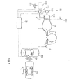
Fig. 1 is schematically illustrating a passenger protecting apparatus which is not an embodiment of the present invention, mounted on the right side wall of a vehicle. -
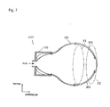
Fig. 2 illustrates an air bag housed in a retainer in the passenger protecting apparatus shown inFig. 1 . -
Fig. 3 illustrates the process of deployment and expansion of the air bag in the passenger protecting apparatus ofFig. 1 . -
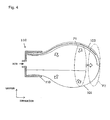
Fig. 4 illustrates the completion of deployment and expansion of the air bag in the passenger protecting apparatus ofFig. 1 . -
Fig. 5 illustrates housing of the air bag into the retainer in a modification of the passenger protecting apparatus ofFigs. 1-4 . -
Fig. 6 illustrates housing of the air bag into the retainer in the passenger protecting apparatus ofFig. 5 . -
Fig. 7 illustrates the completion of deployment and expansion of the air bag in the passenger protecting apparatus ofFig. 5 . -
Fig. 8 illustrates an embodiment of the passenger protecting apparatus of the present invention, mounted on a vehicle (automobile). -
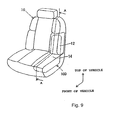
Fig. 9 is a perspective view of a vehicle seat housing the passenger protecting apparatus ofFig. 8 . -
Fig. 10 illustrates the sectional structure of the vehicle seat shown inFig. 9 taken along a line A-A. -
Fig. 11 illustrates the sectional structure of the passenger protecting apparatus ofFig. 8 in an "initial control" state. -
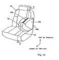
Fig. 12 is a perspective view of the vehicle seat when the passenger protecting apparatus ofFig. 8 is in the "collision foreseeing control" state. -
Fig. 13 illustrates the sectional structure of the vehicle seat shown inFig. 12 taken along a line B-B. -
Passenger protecting apparatuses 100 will be described, with diverse modifications, with reference toFigs. 1 to 13 , wherein onlyFigs. 8-13 show an embodiment of the present invention and then, passenger protecting apparatuses 400, 500 and 600 not representing embodiments of the vehicle passenger protecting apparatus of the present invention will be described with reference to Figs. 14 to 23. Theapparatuses 100 are broadly classified as cases using an air bag for passenger protection, and the apparatuses 400, 500, 600 are broadly classified as cases using a movable protecting pad for passenger protection. - In
Figs. 1 to 23 , description is based on passenger protecting apparatuses installed to the right in the vehicle compartment. - A
passenger protecting apparatus 100 attached to aright side wall 220 of a vehicle 200 (automobile) is schematically illustrated inFig. 1 . Theright side wall 220 is a side door trim or a pillar of the vehicle. Thispassenger protecting apparatus 100 may be attached to the portion in the interiorright side wall 220 to the right of the seat (right end of the seat). - As shown in
Fig. 1 , upon occurrence of a vehicle accident such as a side collision, e.g. with avehicle 210, or a roll-over of thevehicle 200, thepassenger protecting apparatus 100 has a function of protecting a passenger C sitting in aseat 10 of thevehicle 200. Thispassenger protecting apparatus 100 mainly comprises anair bag 101, aretainer 110, anair pump 111, anair tank 113, a fillingvalve 115, a dischargingvalve 117, aradar sensor 120, and a control unit (ECU) 130. - Upon occurrence of a vehicle accident such as a side collision or a roll-over of the
vehicle 200, theair bag 101 has a function of protecting the passenger C by intervening in the passenger protecting region between the passenger C and theright side wall 220. The details will be described later. Thisair bag 101 is expandable and contractible, and is deployed and expanded in the passenger protecting region prior to occurrence of a collision of thevehicle 200. Thisair bag 101 before deployment and expansion is housed in aretainer 110 in a state folded into the predetermined shape in advance. - The detailed configuration of the
air bag 101 will now be described with reference toFig. 2. Fig. 2 illustrates theair bag 101 housed in theretainer 110 in thepassenger protecting apparatus 100 shown inFig. 1 . InFig. 2 , the right side in the drawing represents the inside of the compartment. - As shown in
Fig. 2 , aspring member 103 is secured to the inner wall of theair bag 101. Thespring member 103 is a spring having a function of imparting an elastic energizing force to the air bag so that theair bag 101 wound into a roll shape is housed in theretainer 110. More specifically, a spring made of a resin formed into a coil shape can be used as aspring member 103. As a result, when air for expansion is not fed into theair bag 101, theair bag 101 is housed in the retainer in the form of a wound roll. - Referring again to
Fig. 1 , theair pump 111 compresses air (to a higher pressure) and supplies the resultant compressed air to theair tank 113. Theair tank 113 is a tank having a function of temporarily storing the compressed air supplied from theair pump 111. The fillingvalve 115 is installed in the air feeding path provided between theair bag 101 housed in theretainer 110 and theair tank 113, and conducts opening and closing of the air feeding path. the air discharging path for communicating of theair bag 101 housed in the retainer inside with the outside, and performs opening and closing of the air discharging path. - The
radar sensor 120 is mounted on the side wall of thevehicle 200, and is used for detecting a vehicle at the side which is an object of collision for the vehicle 200 (vehicle 210 inFig. 1 ) or foreseeing a collision of an obstacle on the side. By measuring waves reflected by the object of collision while directing electromagnetic waves having a wavelength of a few millimeters toward the object of collision (milli-wave or a laser beam), a radar known as a "milli-wave radar" or "laser radar", capable of detecting (measuring) detection information (detection signal) such as the distance to the object of collision and the relative speed may be used. - Although not specifically shown, the
control unit 130 comprises a CPU (central processing unit), an input/output unit, a storage unit, and peripheral devices. Thiscontrol unit 130 is electrically connected to theair pump 111, the fillingvalve 115, the dischargingvalve 117, and theradar sensor 120 to exchange detection signals and control signals with these component members. More specifically, detection information (detection signals) detected by theradar sensor 120 is entered as input signals into thecontrol unit 130. Thecontrol unit 130 issues an opening signal or a closing signal to the fillingvalve 115 and the dischargingvalve 117 on the basis of the input signals from theradar sensor 120. - This
control unit 130 may have a configuration for controlling only thepassenger protecting apparatus 100, or a configuration for controlling one or more vehicle component members other than the passenger protecting apparatus, in addition to thepassenger protecting apparatus 100. - Although not specifically shown, a detecting sensor determining whether or not the
vehicle 200 has been subjected to an accident such as a collision or roll-over is provided on thevehicle 200. Detection information (detection signal) detected by this detection sensor is entered as an input signal into thecontrol unit 130. A sensor known as a "acceleration sensor" having a function of permitting detection (measurement) of detection information (detection signal) including accelerations in three axial directions (X-axis, Y-axis and Z-axis) acting on the vehicle is applicable as a detection sensor. - The operation of the
passenger protecting apparatus 100 having the above-mentioned configuration will now be described with reference toFigs. 3 and4 in addition toFigs. 1 and2. Fig. 3 illustrates the process of deployment and expansion of theair bag 101 in thepassenger protecting apparatus 100, andFig. 4 shows theair bag 101 upon the completion of deployment and expansion in thepassenger protecting apparatus 100. InFigs. 3 and4 , the right side of the drawing represents the inside of the compartment. - In
Fig. 1 , theradar sensor 120 constantly detects information relative to an object of collision (a vehicle or an obstacle) on a side of thevehicle 200, the information about collision with thevehicle 210 in this embodiment, and enters the detected information into thecontrol unit 130. On the basis of this information, thecontrol unit 130 foresees a collision by determining the possibility of collision of the vehicle 200 (own vehicle) with the other vehicle 210 (other vehicle). - Upon start of operation of the
vehicle 200, thecontrol unit 130 causes operation of theair pump 111 in a state in which a closing signal is issued to the fillingvalve 115. This permits setting of the pressure in the air tank at a value elevated in advance to a predetermined pressure value. When no object of collision is detected on a side of thevehicle 200 by theradar sensor 120, i.e., when no side collision is foreseen, thecontrol unit 130 outputs an opening signal to the dischargingvalve 117, and issues a closing signal to the fillingvalve 115. As a result, theair bag 101 is never filled with compressed air. - When the
radar sensor 120 detects avehicle 210 near a side of thevehicle 200 and determines a high possibility of a side collision of thevehicle 210 with thevehicle 200, thecontrol unit 130 issues a closing signal to the dischargingvalve 117 prior to occurrence of a side collision of thevehicle 200, and outputs an opening signal to the fillingvalve 115. As a result, compressed air compressed in advance in theair tank 113 is filled (fed) into theair bag 101 through the air feeding path. Theair bag 101 is paid out from the air bag housing position (initial position) shown inFig. 2 against the elastic energizing force of thespring member 103 as shown inFig. 3 for deployment and expansion. This forms a state in which thespring member 103 is paid out in theair bag 101. In the state shown inFig. 3 , representing the process of deployment and expansion of theair bag 101, the passenger-side portion of theair bag 101 has reached the middle position P1. - When filling of compressed air into the
air bag 101 is further continued from the state shown inFig. 3 , theair bag 101 is further deployed and expanded against the elastic energizing force of thespring member 103, and a state in which the passenger-side portion of theair bag 101 is deployed and expanded at the passenger protecting position P2 is achieved. At this point in time, thecontrol unit 130 issues a closing signal to the fillingvalve 115, thereby completing the deployment and expansion of theair bag 101. Thisair bag 101 for which deployment and expansion have been completed before occurrence of a collision is ready for coping with passenger protection upon occurrence of a side collision of thevehicle 210 with thevehicle 200 which can occur subsequently. The air bag housing position (the initial position shown inFig. 2 ) of theair bag 101 corresponds to a first state; the middle position P1 of theair bag 101 corresponds to a second state and the passenger protecting position P2 of theair bag 101 corresponds to a third state. It is also possible to omit the second state and more directly from the first state to the third state, which would then be regarded as a second state. - When the
vehicle 210 actually collides on the side with thevehicle 200, i.e., when the above-mentioned detecting sensor detects occurrence of a collision, the impact force acting on the passenger is alleviated by theair bag 101 of which the deployment and expansion have been completed at the passenger protecting position P2 prior to occurrence of' the collision, thus ensuring passenger protection. - On the other hand, when the possibility of side collision of the
vehicle 210 with thevehicle 200 has once been determined to be high, but actually, the side collision is avoided, and theradar sensor 120 no further detects an object of collision on a side of thevehicle 200, thecontrol unit 130 performs control so as to house theair bag 101 into theretainer 110. More specifically, thecontrol unit 130 issues an opening signal to the dischargingvalve 117 to discharge the air contained in theair bag 101 to outside theair bag 101 via the air discharging path. As a result, theair bag 101 in the state shown inFig. 4 forms the state shown inFig. 3 , and then, is wound into a roll shape in accordance with the elastic energizing force of thespring member 103 to return to the housing position shown inFig. 2 . That is, the state in which thespring member 103 is wound is achieved in theair bag 101. As described above, theair bag 101 is reversibly operable in a direction approaching the passenger and in a direction away from the passenger between the housing position (initial position) shown inFig. 2 and the passenger protecting position (deployment/expansion completing position) P2 shown inFig. 4 . - A configuration other than the one shown in
Fig. 2 may be used for the configuration of theair bag 101. The configuration and the operation of apassenger protecting apparatus 100 having some modifications will now be described with reference toFigs. 5 to 7 . In thepassenger protecting apparatus 100 ofFigs. 5 to 7 , anair bag 101 similar to that in thepassenger protecting apparatus 100 ofFigs. 1 to 4 is used. -
Fig. 5 illustrates theair bag 101 housed in theretainer 110 in thepassenger protecting apparatus 100.Fig. 6 shows the process of deployment and expansion of theair bag 101 in thepassenger protecting apparatus 100.Fig. 7 represents theair bag 101 upon completion of deployment and expansion in thepassenger protecting apparatus 100. InFigs. 5 to 7 , the right side of the drawing represents the inside of the compartment. - An
elastic member 303 is secured by sewing to the inner wall of theair bag 101 in thepassenger protecting apparatus 100 shown inFig. 5 . Thiselastic member 303 has a function of imparting an elastic energizing force to theair bag 101 so that theair bag 101 in a state folded into a bellow (accordion-shape) is housed in theretainer 110. More specifically, an elastic-cord-like member is applicable as anelastic member 303. As a result, when air for expansion is not fed into theair bag 101, theair bag 101 is housed in the retainer in a state folded into a bellow shape. - In this configuration of the
passenger protecting apparatus 100, when thecontrol unit 130 determines that the possibility of a side collision of thevehicle 210 with thevehicle 200 is high, and compressed air is fed to theair bag 101, theair bag 101 is released from the folding state against the elastic energizing force of theelastic member 303 as shown inFig. 6 from the air bag housing position (initial position) shown inFig. 5 , and is deployed and expanded. That is, an elongated state of theelastic member 303 is achieved in theair bag 101. The state shown inFig. 6 is the process of deployment and expansion of theair bag 101, in which a passenger-side portion of theair bag 101 has reached the middle point P1. - When the
air bag 101 is further filled with compressed air from the state shown inFig. 6 , theair bag 101 is further deployed and expanded against the elastic energizing force of theelastic member 303, and the passenger-side portion of theair bag 101 is deployed and expanded to the passenger protecting position P2. Thisair bag 101 for which the deployment and expansion have been completed prior to occurrence of a collision is prepared for passenger protection upon occurrence of vehicle collision of thevehicle 210 with thevehicle 200 which can occur subsequently. - When the
vehicle 210 actually collides with a side of thevehicle 200, the impact force acting on the passenger is alleviated by theair bag 101 for which the deployment and expansion have been completed at the passenger protecting position P2 prior to occurrence of the collision, thus ensuring passenger protection. On the other hand, when the possibility of side collision of thevehicle 210 with thevehicle 200 has once been determined to be high, but actually, the side collision is avoided and theradar sensor 120 no further detects an object of collision on the side of thevehicle 200, theair bag 101 in the state shown inFig. 7 achieves the state shown inFig. 6 , and then, is folded into a bellow shape in accordance with the elastic energizing force of theelastic member 303 and returns to the housing position shown inFig. 5 . That is, theelastic member 303 is contracted in theair bag 101. As described above, theair bag 101 is reversibly operable in a direction approaching the passenger and in a direction away from the passenger between the housing position (initial position) shown inFig. 5 and the passenger protecting position P2 (deployment/expansion completing position) shown inFig. 7 . - A further variation of the
passenger protecting apparatus 100 representing an embodiment of the present invention will now be described with reference toFigs. 8 to 13 . InFigs. 8 to 13 again, the passenger protecting apparatus used for the vehicle passenger on the right vehicle seat is described. The configuration of the passenger protecting apparatus of this embodiment is similarly applicable to any of the passengers on vehicle seats including the driver's seat, the assistant driver's seat, and the rear seats. - The
passenger protecting apparatus 100 of this embodiment, as mounted on a vehicle 200 (automobile), is schematically illustrated inFig. 8 . Although details will be described later, thispassenger protecting apparatus 100 is attached in this embodiment to thevehicle seat 10 on which the vehicle passenger C is seated, in contact to thepassenger protecting apparatuses 100 ofFigs. 8 to 13 . In addition to thispassenger protecting apparatus 100, the configuration may comprise another passenger protecting apparatuses mounted on body side members such as a trim or a pillar. - In
Figs. 8-13 , elements similar or equivalent to those ofFigs. 1-7 bear the same reference numerals. Thispassenger protecting apparatus 100 mainly comprises anair bag 101, anair pump 111, anair tank 113, acontrol valve 116, and a control unit (ECU) 130, i.e. in contrast to the previously discussedapparatuses 100 ofFigs. 1 to 7 , only one valve is present. The components including aradar sensor 120 mounted on thevehicle 200 may be regarded as thepassenger protecting apparatus 100. - Upon occurrence of a vehicle accident such as a side collision or a roll-over of the
vehicle 200, theair bag 101 has a function of protecting the passenger C by intervening in the passenger protecting region of the vehicle passenger C. The details will be described later. In this embodiment, thisair bag 101 again is expandable and contractible, and is deployed and expanded in the passenger protecting region prior to occurrence of a collision of thevehicle 200. As this passenger protecting region, the region between the vehicle passenger C and the vehicle side wall, or a region in front of the vehicle passenger C is adopted. Thisair bag 101 before deployment and expansion is housed in thevehicle seat 10 in a state folded into a predetermined shape in advance. - Although not specifically shown, the
control unit 130 comprises a CPU (central processing unit), an input/output unit, a storage unit, and peripheral devices. In this embodiment, thiscontrol unit 130 is electrically connected to the driving means (actuator) 106, theair pump 111, thecontrol valve 116 and theradar sensor 120 to exchange detection signals and control signals with these component members. More specifically, detection information , (detection signals) detected by theradar sensor 120 is entered as input signals into thecontrol unit 130. Thecontrol unit 130 issues a driving signal to the driving means 106, a start or stop signal to theair pump 111, and an opening adjusting signal to thecontrol valve 116 on the basis of an input signal from theradar sensor 120. - This
control unit 130 may have a configuration for controlling only thepassenger protecting apparatus 100, or a configuration for controlling the vehicle component members other than the passenger protecting apparatus, in addition to thepassenger protecting apparatus 100 or for controlling the vehicle as a whole simultaneously. - The
radar sensor 120 is mounted on the side wall of thevehicle 200, and is used for detecting a vehicle at the side which is an object of collision for the vehicle 200 (vehicle 210 inFig. 8 ) as already described with reference toFigs. 1-7 . - The detailed configuration of the above-mentioned
passenger protecting apparatus 100 ofFig. 8 will now be described with reference toFigs. 9 and10 .Fig. 9 is a perspective view of thevehicle seat 10 in a state in which thepassenger protecting apparatus 100 of this embodiment is housed in the vehicle seat.Fig. 10 illustrates a sectional structure of thevehicle seat 10 shown inFig. 9 cut along the line A-A. In theseFigs. 9 and10 , thepassenger protecting apparatus 100 is incorporated into thevehicle seat 10, and control by thecontrol unit 130 is not as yet executed. - As shown in
Fig. 9 , thepassenger protecting apparatus 100 of this embodiment is housed in portions of the vehicle set 10 corresponding to the seat'back side portion and the seat cushion side portion. More specifically, as shown inFig. 10 , theair bag 101, areturn spring 203, and alatch member 105 are arranged on the seat backside member 12 on the vehicle rear side. Theair pump 111, theair tank 113 and thecontrol valve 116 are arranged below the seatcushion side member 14. - The seat back
side member 12 has a configuration covering the vehicle front side of theair bag 101, and comprises aconcave housing portion 12a, arotation shaft 12b, and anengagement portion 12c. Thehousing portion 12a serves as a housing space which houses theair bag 101 in the initial state or first state folded in advance in a predetermined shape. Therotation shaft 12b is fixed to thevehicle seat 10 side, and serves as a rotation fulcrum allowing rotation in thearrow 20 and thearrow 22 directions inFig. 10 of the seat back side member relative to thevehicle seat 10. The engagement portion 112c is a portion with which is engaged the other end of areturn spring 203 having an end fixed to thevehicle seat 10 side, and is also a portion engageable with theleading end 105a of alatch member 105. Thelatch member 105 is made rotatable in thearrow 20 and thearrow 22 directions inFig. 10 around therotation shaft 105b by a driving means (actuator) 106 such as an electric motor. - The seat back
side member 12 having the above-mentioned configuration can rotate between a first set position shown inFig. 10 and a second set position shown inFig. 13 as described later, with therotation shaft 12b as the fulcrum, and is elastically energized to the first set position by areturn spring 203 serving as an example for an elastic spring in the sense of the present invention. Applicable return springs 203 include various types of elastic springs capable of imparting an elastic energizing force such as a coil-shaped and sheet-shaped springs. This seat backside member 12 has a configuration in which, theengagement portion 12c thereof engages with (hooks with) theleading end 105a of thelatch member 105 driven by the driving means 106, and this prevents rotation thereof in thearrow 20 direction. - The
air pump 111 is a pump having a function of compressing the air (to a high pressure) and feeding the compressed air into theair tank 113. Theair tank 113 is a tank having a function of temporarily storing the compressed air fed from theair pump 111. - The
control valve 116, installed in an air feeding path between theair bag 101 and theair tank 113, is a valve having a function of feeding the compressed air into theair bag 101 via theair feeding section 116a and discharging the air outside theair bag 101 via theair discharging section 116b from the interior of theair bag 101. - Accordingly, in the
passenger protecting apparatus 100 shown inFig. 8 , thevalves Fig. 1 have been replaced by asingle valve 116. As a matter of course, also in a passenger protecting apparatus accommodated in a seat like the one shown inFigs. 8-13 two valves may be used, or one valve may be used in passenger protecting apparatus accommodated in a side wall of a vehicle. - Operation of the
passenger protecting apparatus 100 having the above-mentioned configuration will now be described with reference toFigs. 8 to 10 , and further, toFigs. 11 to 13 .Fig. 11 illustrates a sectional structure of thepassenger protecting apparatus 100 of this embodiment in the "initial control" state.Fig. 12 is a perspective view of thevehicle seat 10 in a "collision foreseeing control" state of the passenger protecting apparatus of this embodiment; andFig. 13 illustrates a sectional structure of thevehicle seat 10 shown inFig. 12 cut along the line B-B. - In
Fig. 8 , theradar sensor 120, similar toFig. 1 , detects information about vehicle collision of an object of collision (vehicles, obstacles, etc.) on the side of thevehicle 200, i.e., of thevehicle 210 in this embodiment, constantly or at certain time intervals, and enters the detected information into thecontrol unit 130. Thecontrol unit 130 foresees a vehicle collision by determining the possibility of the vehicle 200 (own vehicle) colliding with a vehicle 210 (other vehicle). In response to this collision foreseeing information, thecontrol unit 130 executes controls such as "initial control", "collision foreseeing control", "collision occurrence control", and "collision avoidance control" described later. - At the same time as the start of operation of the
vehicle 200, thecontrol unit 130 activates theair pump 111. Therefore, the pressure in theair tank 113 is set in a state elevated to a first pressure in advance. When an object of collision is not detected on a side of thevehicle 200 by theradar sensor 120, i.e., when a side collision is not foreseen, thecontrol unit 130 carries out initial control. By this initial control, thecontrol unit 130 adjusts the pressure in theair bag 101 to a second pressure lower than the first pressure in theair tank 113. More specifically, thecontrol unit 130, while issuing a signal for closing theair discharging section 116b to thecontrol valve 116, outputs a signal for once opening theair feeding section 116a, adjusts the pressure in theair bag 101 to the second level, and issues a signal for closing theair feeding section 116a. As a result, theair bag 101 expands in thehousing portion 12a of the seat backside member 12, as shown inFig. 11 , and the inner pressure thereof is kept at the second level. - The
control unit 130 issues a control signal to the driving means 106 so as to hold a state in which theleading end 105a of thelatch member 105 engages with (is caught by) theengagement portion 12c of the seat backside member 12, as shown inFig. 11 . In this initial control state shown inFig. 11 , the seat backside member 12 is elastically energized by thereturn spring 203 to the first set position, and the rotation in thearrow 20 direction is prevented by thelatch member 105. - When the
vehicle 210 approaching a side of thevehicle 200 is detected by theradar sensor 120, and the possibility of thevehicle 210 side-colliding with thevehicle 200 is determined to be high, a collision foreseeing control is conducted. Thecontrol unit 130 issues a signal for opening theair feeding section 116a and for closing theair discharging section 116b to thecontrol valve 116, prior to occurrence of the vehicle side collision. As a result, the compressed air of the first pressure by compression applied in advance in theair tank 113 is gradually filled in theair bag 101 via theair feeding section 116a. - As shown in
Fig. 13 , thecontrol unit 130 issues a control signal to the driving means 106 so as to cancel the engaged state (hooked state) of the leading and 105a of thelatch member 105 with the engagement portion of the seat backside member 12. In the state of this collision , foreseeing control shown inFig. 13 , the seat backside member 12 is allowed to make rotation in thearrow 22 direction against the elastic energizing force of thereturn spring 203. At this point in time, theair bag 101 is deployed and expanded from the ordinary housed state shown inFig. 11 (the ordinary initial state or first state in which theair bag 101 is housed) to the collision-preparing state or second state shown inFig. 12 (the state for preparing for actual vehicle collision upon occurrence thereof (preliminary state)). The pressing force of theair bag 101 surpasses the elastic energizing force of thereturn spring 203. As a result, the seat backside member 12 moves by rotation from the first set position shown inFig. 11 in thearrow 20 direction to the second set position shown inFig. 13 . Theair bag 101 is deployed and expanded along with this into a collision-preparing state in the collision-preparing region. This expandedair bag 101 in the collision-preparing state in the collision-preparing region is kept for passenger protection upon possible subsequent occurrence of a side collision of thevehicle 210 with thevehicle 200. The collision-preparing region shown inFig. 13 has a configuration of a region lying between the vehicle side wall and the side of the vehicle passenger (head, neck, shoulder, chest, abdomen, knees and lower limbs). In this embodiment, theair bag 101 has such a configuration that the collision-preparing state is closer to the vehicle passenger C than the ordinary housed state, thus permitting rapid coping with passenger protection upon occurrence of a vehicle accident in the collision occurrence control described later. - The state of the
air bag 101 shown inFig. 10 may be adopted as a housed state or first state. - When the
vehicle 210 actually side-collides with thevehicle 200 subsequently, i.e., when occurrence of a vehicle collision is detected by the detecting sensor having the above-mentioned configuration, the inner pressure of theair bag 101 is maintained for theair bag 101 deployed and expanded as a collision-preparing state in the collision-preparing region prior to occurrence of the vehicle collision in the collision foreseeing control, or the pressure is adjusted to a lower level by thecontrol valve 116. Under the effect of thisair bag 101, the impact force acting on the side of the vehicle passenger (vehicle passenger C inFig. 8 ) (head, neck, shoulder, chest, abdomen, knees, and lower limbs) is alleviated, thereby ensuring passenger protection. In other words, in this embodiment, the collision-preparing region serve as a region substantially in agreement with the passenger protecting region protecting the vehicle passenger C, and the collision-preparing state of theair bag 101 serves as the passenger protecting state as it is. - Regarding this collision occurring control, the
air bag 101 deployed and expanded as a collision-preparing state in the collision-preparing region prior to occurrence of the vehicle cushion in the collision foreseeing control may further be deployed and expanded as a passenger protecting state in a region different from the collision-preparing region, so as to protect the vehicle passenger C in that region. In this case, the collision-preparing region is formed as a region different from the passenger protecting region which protects the vehicle passenger C. Such a region may be formed as a region lying between the vehicle side wall and the side or the front of the vehicle passenger C (head, neck, shoulder, chest, abdomen, knees and lower limbs). This alleviates the impact force acting on the side or the front of the vehicle passenger C, thus ensuring passenger protection. In other words, in this embodiment, the collision-preparing region is a region different from the passenger protecting region when the vehicle passenger C is protected, and the collision-preparing state of theair bag 101 is configured as a state different from the passenger protecting state. - In this configuration, a series of operations of the
air bag 101 ranging from the ordinary housed state, through the collision preparing state, to the passenger protecting state can be carried out more smoothly by setting the collision preparing state so that theair bag 101 in standby prior to the vehicle collision does not disturb the vehicle passenger as far as possible. In this configuration, it suffices that theair bag 101 operations at least between the ordinary housed state and the collision preparing state be reversible or the configuration may be returnable from the passenger protecting state to the collision preparing state, or, after occurrence of the vehicle accident, it may be an irreversible configuration which does not return from the passenger protecting state to the collision preparing state. - On the other hand, when, once determining that the possibility is high for the
vehicle 210 to collide with thevehicle 200, the side collision is actually avoided, and the object of collision is no further detected on a side of thevehicle 200 by theradar sensor 120, thecontrol unit 130 performs control so as to cause contraction of theair bag 101 as the ordinary housed state (the state shown inFig. 10 or inFig. 11 ). - In other words, the
control unit 130 adjusts the pressure in theair bag 101 to a lower level by this collision avoidance control. More specifically, a signal for opening theair discharge section 116b is issued to thecontrol valve 116. This causes the pressing force of theair bag 101 to comply with the elastic energizing force of thereturn spring 203, and the seat backside member 12 rotates from the second set position shown inFig. 13 to the first set position shown inFig. 11 in thearrow 22 direction, and theair bag 101 contracts as an ordinary housed state. In this embodiment, theair bag 101 is reversibly operable between the ordinary housed state shown inFig. 10 or11 and the collision-preparing state shown inFig. 13 . - Subsequently the
control unit 130 activates theair pump 111 as in the initial control described above, sets the pressure in theair tank 113 in a state elevated in advance to the level of the first pressure, adjusts the pressure in theair bag 101 to the second pressure lower than the first pressure in theair tank 113 to prepare for the next collision foreseeing control. - According to this embodiment, the seat back
side member 12 forming a part of the vehicle seat is used also as an air bag cover which covers theair bag 101, thereby permitting rational use of component parts. - According to this embodiment, the seat back
side member 12 as the air bag cover is operated by the utilization of the expansion force of theair bag 101 and the elastic energizing force of thereturn spring 103, thus permitting simplification of the structure. - In the above-mentioned embodiment of
Figs. 8 to 13 , the case has been described in which the seat backside member 12 serving as the air bag cover is operated by using the expansion force of theair bag 101 and the elastic energizing force of thereturn spring 203. - The above-mentioned embodiment has described cases where the
passenger protecting apparatus 100 is housed over portion corresponding to the seat back side portion and the seat cushion side portion from among the various portions of thevehicle seat 10. In the present invention; the configuration is required only to be such that the passenger protecting means such as the air bag is operated reversibly between the ordinary housed state and the collision-preparing state, this making it possible to mount the passenger protecting apparatus at various portion of the vehicle seat. - In the above-mentioned embodiment, the case where the
air bag 101 is the state shown inFig. 11 (inner pressure is held at a second pressure) is deployed and expanded in the state shown inFig. 13 in the collision foreseeing control has been described. In the present invention, however, the configuration may be such that theair bag 101 in the state shown inFig. 10 is deployed and expanded in the state shown inFig. 13 through the state shown inFig. 11 or as it is. - According to the
passenger protecting apparatuses 100 of the first embodiment, as described above with reference toFigs. 8-13 , it is possible to achieve a configuration using theair bag 101 for ensuring rapid passenger protection upon occurrence of a vehicle accident. More specifically, in this embodiment, when a vehicle collision is foreseen, theair bag 101 can be expanded in advance from the ordinary housed state to the collision-preparing state to prepare for a subsequent occurrence of an accident. This permits rapid execution of passenger protection upon occurrence of a vehicle accident as it is by using anair bag 101 expanded in advance before the vehicle collision so as to achieve the collision-preparing state. Particularly as in this embodiment, by adapting a configuration in which the passenger protecting means 100 is attached to the vehicle seat arranged in the proximity of, or in close contact with, the vehicle passenger, it is possible to more rapidly cope with passenger protection upon occurrence of a vehicle accident. In this embodiment, when the vehicle collision does not actually occurs, it is possible to cause theair bag 101 to return from the collision-preparing state to the ordinary housed state to prepare for the next collision forecasting, thus providing a rational configuration. - By using the
passenger protecting apparatus 100 of this embodiment as described above, passenger protection upon occurrence of a vehicle accident can be rapidly coped with by use of theair bag 101 deployed and expanded so as to achieve a collision-preparing state in advance before the vehicle collision. - The present invention is not limited to the above-mentioned embodiments, but various applications and variations are conceivable. For example, the following embodiments can be achieved by applying the above-mentioned embodiments.
- In the above-explained embodiment, the
passenger protecting apparatus 100 which protects the passenger C sitting in a seat to the right of the vehicle, by being accommodated in a right vehicle seat have been presented as example. A passenger protecting apparatus for protecting a passenger sitting in the left seat of the vehicle can similarly be installed. In the present invention, thepassenger protecting apparatus 100 can be located at a different portion of the seat. For example, a passenger protecting apparatus having a configuration similar to that of thepassenger protecting apparatus 100 can be incorporated in the seat, for example at a seat side portion including a portion opposite to the vehicle side wall or the front portion of the seat cushion. - At the time of a vehicle accident, a passenger sitting in a seat tends to move forward from the seat or diagonally downward from the seat by slipping through the seat belt. The present invention is applicable to a passenger protecting apparatus for ensuring passenger protection by preventing this tendency known as a "submarine phenomenon". The submarine phenomenon can be prevented, for example, by incorporating an expanding article such as an air bag in the front portion of the seat cushion, expanding the expanding article, when a vehicle collision is foreseen, to cause the front portion of the seat cushion to bulge upward in advance, thereby lifting up the femora of the passenger, thereby preventing the submarine phenomenon from occurring in a collision. Or, the submarine phenomenon can be prevented in a collision by providing a protecting pad (protecting board) in the front portion of the seat cushion, and moving the protecting pad (protecting board) up above the seat in advance when a vehicle collision is foreseen to lift up the femora of the passenger.
- As described above, the present invention is not limited to technique for ensuring passenger protection in a side collision as in the above-mentioned embodiments, but is applicable to techniques for ensuring passenger protection also in front collision.
- The above-mentioned embodiments cover cases where passenger protecting means such as an
air bag 101 is arranged at the passenger protecting position P2 before a vehicle collision, and upon occurrence of a vehicle accident, the passenger is protected at the passage protecting position P2. In the present invention, however, it is possible to use a configuration in which the passenger protecting means is arranged at a position more distant toward the vehicle than the passenger protecting position P2 prior to the vehicle collision. More particularly, as already pointed out passenger protection can be achieved by arranging the passenger protecting means at a middle position P1 in advance before occurrence of a vehicle collision, and upon occurrence of the vehicle accident, moving the passenger protecting means from the middle position P1 to the passenger protecting position P2 (the "third position" in the present invention). - In the above-mentioned embodiments, the configurations of the vehicle passenger protecting apparatuses mounted on an automobile have been described. The present invention is also applicable to a vehicle passenger protecting apparatus mounted on any of various vehicles other than an automobile such as a train, a ship and the like.
Claims (9)
- A vehicle seat (10) with a vehicle passenger protecting apparatus (100), comprising:passenger protecting means (101) which, upon occurrence of a vehicle collision, protects a passenger (C) on the seat (10) of said vehicle (200);wherein said passenger protecting means comprises an expandable/contractible air bag (101);driving means (111, 113, 116, 116a, 116b; 402; 502; 602) capable of driving said passenger protecting means (101; 401),wherein said driving means comprises gas feeding means (111, 113, 116, 116a) capable of feeding a gas for expansion into the interior of said air bag (101); andan air bag cover (12) covering said air bag (101) forms a part of said vehicle seat (10), and is operable between a first set position where said air bag cover (12) covers said air bag (101) in a first state and a second set position where said air bag cover (12) allows expansion leading to a second state of said air bag (101),characterized in that
said driving means (111, 113, 116, 116a, 116b; 402; 502; 602) are capable of driving said passenger protecting means (101; 401) reversibly between said first state and a collision-preparing second state and comprise gas discharging means (116, 116b) capable of discharging the gas from the interior of said air bag (101);
control means (130) which controls said driving means (111, 113, 116, 116a, 116b);
wherein:said control means (130) is adapted to control, when a vehicle collision is foreseen, said gas feeding means (111, 113, 116, 116a) and said gas discharging means (116, 116b) so as to cause said air bag (101) to expand into said second state prior to the vehicle collision and to control said gas feeding means (111, 113, 116, 116a) and said gas discharging means so as to cause said air bag to contract into said first state when a vehicle collision is avoided,and in that the vehicle passenger protection apparatus (100) further comprises an energizing means (103) for energizing said air bag (101) to said first state such that said air bag (101) expands into said second state against an energizing force provided by said energizing means (103) and collapses into said first state supported by said energizing force. - The vehicle seat (10) according to claim 1,
the vehicle passenger protection apparatus (100) comprising detecting means (120) for detecting information about a collision of said vehicle (200), wherein the control means (130) are adopted to control said driving means (111, 113, 116, 116a, 116b) when said detecting means (120) foresees a vehicle collision. - The vehicle seat (10) according to claim 1 or claim 2,
wherein said second state is a state where said passenger protecting means (101) is closer to said passenger (C) of said vehicle (200) than in said first state. - The vehicle seat (10) according to any one of the preceding claims,
wherein said first state is a housed state. - The vehicle seat (10) according to any one of the preceding claims, wherein:said air bag cover (12) is elastically energized by an elastic spring (203) to said first set position; andduring the process of expansion into said second state, said air bag (101) presses said air bag cover (12) from said first set position to said second set position against the elastic energizing force of said elastic spring (203), and during the process of contraction into said first state, said air bag (101) is pressed, into said first state by said air bag cover (102) operating to said first set position in accordance with the elastic energizing force of said elastic spring (203).
- The vehicle seat (10) according to any one of the preceding claims, wherein
said second state corresponds to a position in a passenger protecting region in which the passenger (C) is protected; and
said control means (130) is adapted to control, upon occurrence of a vehicle collision, said driving means (111, 113, 116, 116a, 116b) so as to arrange said passenger protecting means (101) in said second state, whereby the passenger (C) is protected via said passenger protecting means (101). - The vehicle seat (10) according to any one of claims 1 to 6, wherein:said second state corresponds to a position spaced apart from a passenger protecting region where the passenger (C) is protected andsaid control means (130) is adapted to control, upon occurrence of an accident of the vehicle (200), said driving means (111, 113, 116, 116a, 116b) so as to arrange said passenger protecting means (101) from said second state to a third state corresponding to a position in said passenger protecting region, whereby the passenger (C) is protected via said passenger protecting means.
- The vehicle seat (10) according to claim 7,
wherein said second state corresponds to a position spaced apart from said passenger protecting region towards a side portion of said vehicle (200). - A passenger-protecting vehicle (200) having the vehicle seat (10) of any one of claims 1 to 8.
Applications Claiming Priority (4)
| Application Number | Priority Date | Filing Date | Title |
|---|---|---|---|
| JP2004018298 | 2004-01-27 | ||
| JP2004018298A JP2005212504A (en) | 2004-01-27 | 2004-01-27 | Occupant protective device for vehicle |
| JP2004373908 | 2004-12-24 | ||
| JP2004373908A JP4588438B2 (en) | 2004-12-24 | 2004-12-24 | Occupant protection device, vehicle with occupant protection device |
Publications (3)
| Publication Number | Publication Date |
|---|---|
| EP1559622A2 EP1559622A2 (en) | 2005-08-03 |
| EP1559622A3 EP1559622A3 (en) | 2005-12-28 |
| EP1559622B1 true EP1559622B1 (en) | 2013-05-22 |
Family
ID=34656277
Family Applications (1)
| Application Number | Title | Priority Date | Filing Date |
|---|---|---|---|
| EP05001737.5A Expired - Fee Related EP1559622B1 (en) | 2004-01-27 | 2005-01-27 | Vehicle passenger protecting apparatus |
Country Status (2)
| Country | Link |
|---|---|
| US (1) | US7380821B2 (en) |
| EP (1) | EP1559622B1 (en) |
Families Citing this family (30)
| Publication number | Priority date | Publication date | Assignee | Title |
|---|---|---|---|---|
| DE10252180B4 (en) * | 2002-11-09 | 2007-08-16 | Suspa Holding Gmbh | Active impact protection |
| JP4779879B2 (en) * | 2005-11-11 | 2011-09-28 | 日産自動車株式会社 | Occupant protection device and occupant protection method during vehicle rollover |
| DE102005062849A1 (en) * | 2005-12-23 | 2007-09-06 | Takata-Petri Ag | Occupant restraint device for a motor vehicle |
| JP4940772B2 (en) * | 2006-06-13 | 2012-05-30 | 日産自動車株式会社 | Airbag device |
| DE102007007002B4 (en) * | 2007-02-08 | 2010-06-02 | Autoliv Development Ab | safety device |
| JP5501772B2 (en) | 2007-03-15 | 2014-05-28 | タカタ・ペトリ アーゲー | Vehicle seat device |
| DE102007013105A1 (en) | 2007-03-15 | 2008-09-18 | Takata-Petri Ag | Occupant protection device for an occupant of a motor vehicle |
| DE102007044824B4 (en) * | 2007-09-20 | 2019-07-04 | Autoliv Development Ab | Safety device for a motor vehicle seat and motor vehicle seat |
| JP5485990B2 (en) | 2008-07-15 | 2014-05-07 | タカタ・ペトリ アーゲー | Vehicle seat device for automobile and vehicle occupant protection method |
| JP2011000962A (en) * | 2009-06-18 | 2011-01-06 | Honda Motor Co Ltd | Airbag device of saddle-riding type vehicle |
| US8888129B2 (en) * | 2011-01-31 | 2014-11-18 | Simon Fraser University | Inflation method and apparatus for an airbag |
| DE102013009673A1 (en) * | 2013-06-08 | 2014-12-11 | Brose Fahrzeugteile Gmbh & Co. Kommanditgesellschaft, Hallstadt | Collision protection method and collision protection device for an adjustable vehicle part |
| DE102013216583A1 (en) * | 2013-08-21 | 2015-02-26 | Robert Bosch Gmbh | Method and device for regulating a filling of an airbag for a vehicle and airbag system |
| US9376067B2 (en) | 2014-11-04 | 2016-06-28 | Nissan North America, Inc. | Vehicle interior trim assembly |
| JP6944930B2 (en) | 2016-04-28 | 2021-10-06 | セーレン株式会社 | Base cloth for airbags and airbags |
| CN105857236A (en) * | 2016-06-14 | 2016-08-17 | 胡达广 | Intelligent airbag capable of opening under non-explosive conditions |
| CN206374708U (en) * | 2016-11-14 | 2017-08-04 | 京东方科技集团股份有限公司 | A kind of automobile |
| US10501041B2 (en) * | 2017-08-11 | 2019-12-10 | Ford Global Technologies, Llc | Vehicle airbag system |
| GB201719108D0 (en) * | 2017-11-17 | 2018-01-03 | Xtract360 Ltd | Collision evaluation |
| CN108674265B (en) * | 2018-07-12 | 2024-02-27 | 浙江博安母婴用品有限公司 | Telescopic side protection airbag of child safety seat |
| US10946825B2 (en) * | 2018-12-04 | 2021-03-16 | Ford Global Technologies, Llc | Airbag assembly |
| KR102613182B1 (en) * | 2018-12-18 | 2023-12-14 | 현대자동차주식회사 | Vehicle and method of controlling airbag of vehicle |
| US10864876B2 (en) * | 2019-01-31 | 2020-12-15 | Ford Global Technologies, Llc | Deployable panel for an airbag |
| DE102019104095A1 (en) * | 2019-02-19 | 2020-08-20 | Trw Automotive Gmbh | Vehicle-integrated restraint system |
| US10919477B2 (en) * | 2019-02-21 | 2021-02-16 | Faurecia Interior Systems, Inc. | Deployable vehicle interior door panel |
| JP7214009B2 (en) * | 2019-11-25 | 2023-01-27 | オートリブ ディベロップメント エービー | airbag module |
| DE102020103243A1 (en) | 2020-02-10 | 2021-08-12 | Faurecia Autositze Gmbh | Pneumatic adjustment device for a side bolster of a vehicle seat |
| CN113511159B (en) * | 2020-04-10 | 2023-01-31 | 采埃孚汽车科技(上海)有限公司 | System and method for enhancing safety of driver and passenger through air bag |
| US11318868B1 (en) * | 2020-12-04 | 2022-05-03 | Zoox, Inc. | Side-impact crash structure for a vehicle seat |
| CN112848987B (en) * | 2021-03-02 | 2022-02-18 | 长沙理工大学 | Safety seat device |
Citations (1)
| Publication number | Priority date | Publication date | Assignee | Title |
|---|---|---|---|---|
| EP0953485A1 (en) * | 1998-04-28 | 1999-11-03 | TRW Automotive Safety Systems GmbH & Co. KG | Crash protecting device |
Family Cites Families (42)
| Publication number | Priority date | Publication date | Assignee | Title |
|---|---|---|---|---|
| US4258931A (en) | 1978-08-17 | 1981-03-31 | Lee Joseph K | Air bag system for automobiles |
| JPS55147948A (en) | 1979-05-02 | 1980-11-18 | Mitsubishi Electric Corp | Brush holder device |
| JPS58181621A (en) | 1982-04-20 | 1983-10-24 | Ikeda Bussan Co Ltd | Expansion mold for cushioning pad |
| US5490691A (en) * | 1992-06-30 | 1996-02-13 | Volkswagen Ag | Vehicle safety arrangement for positioning a vehicle occupant |
| US5308112A (en) | 1993-04-21 | 1994-05-03 | General Motors Corporation | Unfurled side impact air bag |
| US5344184A (en) * | 1993-12-21 | 1994-09-06 | Trw Vehicle Safety Systems Inc. | Method and apparatus for restraining a vehicle occupant |
| US5505487A (en) * | 1995-05-15 | 1996-04-09 | Trw Vehicle Safety Systems, Inc. | Side impact head air bag module |
| US5695242A (en) * | 1996-02-15 | 1997-12-09 | Breed Automotive Technology, Inc. | Seat cushion restraint system |
| DE19724628A1 (en) * | 1996-06-27 | 1998-01-02 | Volkswagen Ag | Occupant airbag for motor vehicle |
| US5842717A (en) * | 1996-06-29 | 1998-12-01 | Volkswagen Ag | Motor vehicle occupant protection arrangement |
| JPH10166989A (en) | 1996-12-05 | 1998-06-23 | Nippon Kuatsu Syst Kk | Air bag device |
| US6045151A (en) * | 1997-02-28 | 2000-04-04 | Hoover Universal, Inc. | Seat mounted side air bag with deployment force concentrator |
| DE19720585A1 (en) * | 1997-05-16 | 1998-11-19 | Porsche Ag | Side impact protection device for an occupant of a vehicle |
| US6024377A (en) * | 1997-09-22 | 2000-02-15 | Breed Automotive Technology, Inc. | Low mount airbag deployment system |
| US6170871B1 (en) * | 1998-06-24 | 2001-01-09 | Breed Automotive Technology, Inc. | Inflatable trim panel assembly for safety restraint systems |
| DE19916848B4 (en) * | 1999-04-14 | 2014-10-30 | Volkswagen Ag | Safety device with at least one rear airbag for a motor vehicle |
| EP1046551B1 (en) * | 1999-04-22 | 2003-06-18 | TRW Occupant Restraint Systems GmbH & Co. KG | Knee protection device |
| WO2000071389A1 (en) * | 1999-05-21 | 2000-11-30 | Volkswagen Aktiengesellschaft | Airbag device for a motor vehicle |
| US6357789B1 (en) * | 1999-06-24 | 2002-03-19 | Ts Tech Co., Ltd. | Seat provided with side air bag system |
| DE50010180D1 (en) * | 1999-08-24 | 2005-06-02 | Volkswagen Ag | AIR BAG DEVICE WITH CONTROLLED SEPARATOR |
| JP2001247010A (en) | 1999-12-28 | 2001-09-11 | Takata Corp | Occupant protective device |
| JP4273604B2 (en) | 2000-01-21 | 2009-06-03 | トヨタ自動車株式会社 | Vehicle occupant protection device |
| WO2001081126A1 (en) * | 2000-04-27 | 2001-11-01 | Volkswagen Ag | Airbag device and operating method for the same |
| JP4370689B2 (en) | 2000-05-19 | 2009-11-25 | 豊田合成株式会社 | Head protection airbag device |
| DE10131056A1 (en) * | 2000-06-29 | 2002-05-02 | Volkswagen Ag | Airbag device has flap that is held in opening by engagement elements on only one side and locking elements released when airbag is triggered so that flap moves to open position behind cladding |
| DE10056300A1 (en) * | 2000-11-14 | 2002-06-27 | Siemens Restraint Systems Gmbh | Airbag system for vehicles has pressurized gas supply that feeds gas into airbag via movable airbag connection in definable region of tubular housing on receiving trigger signal |
| US20020130495A1 (en) * | 2001-03-13 | 2002-09-19 | Lotspih John Anthony | Bias flap for side air bags |
| US6641166B2 (en) | 2001-05-25 | 2003-11-04 | General Motors Corporation | Extendable and retractable knee bolster system |
| US6877772B2 (en) * | 2002-01-03 | 2005-04-12 | Trw Vehicle Safety Systems Inc. | Air bag module with occupant engaging flap |
| DE10316543A1 (en) * | 2002-04-11 | 2003-11-13 | Toyoda Gosei Kk | Air bag device |
| US7104566B2 (en) * | 2002-04-25 | 2006-09-12 | Delphi Technologies, Inc. | Airbag module and cover arrangement |
| KR20040015832A (en) * | 2002-08-12 | 2004-02-21 | 현대모비스 주식회사 | Side air bag for a motor vehicle |
| US6846015B2 (en) * | 2002-09-10 | 2005-01-25 | Trw Vehicle Safety Systems Inc. | Energy absorbing knee bolster |
| US6971667B2 (en) * | 2003-01-14 | 2005-12-06 | Autoliv Asp, Inc. | Glove compartment airbag system |
| US6793243B2 (en) * | 2003-02-06 | 2004-09-21 | Key Safety Systems, Inc. | Airbag deployment rate sensor with spool brake |
| US6789819B1 (en) * | 2003-03-20 | 2004-09-14 | Key Safety Systems, Inc. | Sensor for monitoring airbag deployment |
| US7048298B2 (en) * | 2003-09-22 | 2006-05-23 | Key Safety Systems, Inc. | Upward deploying inflatable knee bolster with mechanical guides |
| JP2005170099A (en) * | 2003-12-08 | 2005-06-30 | Toyoda Gosei Co Ltd | Side air bag device |
| US7549672B2 (en) * | 2004-05-27 | 2009-06-23 | Toyoda Gosei Co., Ltd. | Side airbag device |
| JP2006001383A (en) | 2004-06-16 | 2006-01-05 | Toyota Motor Corp | Occupant crash protection device |
| DE102005042313B4 (en) * | 2004-09-08 | 2015-12-31 | Toyoda Gosei Co., Ltd. | Airbag device and airbag folding method |
| JP4822693B2 (en) * | 2004-11-16 | 2011-11-24 | タカタ株式会社 | Airbag device |
-
2005
- 2005-01-27 EP EP05001737.5A patent/EP1559622B1/en not_active Expired - Fee Related
- 2005-01-27 US US11/050,908 patent/US7380821B2/en not_active Expired - Fee Related
Patent Citations (1)
| Publication number | Priority date | Publication date | Assignee | Title |
|---|---|---|---|---|
| EP0953485A1 (en) * | 1998-04-28 | 1999-11-03 | TRW Automotive Safety Systems GmbH & Co. KG | Crash protecting device |
Also Published As
| Publication number | Publication date |
|---|---|
| US20050161921A1 (en) | 2005-07-28 |
| US7380821B2 (en) | 2008-06-03 |
| EP1559622A3 (en) | 2005-12-28 |
| EP1559622A2 (en) | 2005-08-03 |
Similar Documents
| Publication | Publication Date | Title |
|---|---|---|
| EP1559622B1 (en) | Vehicle passenger protecting apparatus | |
| US8820830B2 (en) | Vehicle seat | |
| US10486639B2 (en) | Occupant protection device | |
| US6568743B1 (en) | Active armrest for side impact protection | |
| CN101346262B (en) | Occupant restraint device for a motor vehicle | |
| CN1819938B (en) | An airbag arrangement | |
| US7628349B2 (en) | Inertia actuator for seat belt retractor | |
| CN108454560B (en) | Variable force limiter control system for vehicle | |
| EP2125446B1 (en) | Occupant restraint system | |
| US20220080917A1 (en) | Roof airbag system and vehicle | |
| GB2368518A (en) | An expandable headrest | |
| EP3530526B1 (en) | Airbag apparatus for vehicle | |
| CN110325408B (en) | Vehicle occupant restraint device and method for operating a vehicle occupant restraint device | |
| JP5962602B2 (en) | Front seat airbag system | |
| JP2021017164A (en) | Occupant protection device | |
| CN113428105A (en) | Vehicle seat incorporating a seat bottom front edge airbag | |
| JP7451114B2 (en) | Occupant protection device | |
| EP2014522B1 (en) | Occupant protection device | |
| EP1741605B1 (en) | Vehicle passenger-restraining system and method | |
| US10807551B2 (en) | Vehicle seat with deployable panel | |
| JP7168496B2 (en) | passenger protection device | |
| JP4588438B2 (en) | Occupant protection device, vehicle with occupant protection device | |
| KR102043045B1 (en) | Airbag apparatus of vehicle | |
| EP1031475A2 (en) | Protection system for rear impact crashes | |
| JP4134857B2 (en) | Protective device for passenger seat of vehicle |
Legal Events
| Date | Code | Title | Description |
|---|---|---|---|
| PUAI | Public reference made under article 153(3) epc to a published international application that has entered the european phase |
Free format text: ORIGINAL CODE: 0009012 |
|
| AK | Designated contracting states |
Kind code of ref document: A2 Designated state(s): AT BE BG CH CY CZ DE DK EE ES FI FR GB GR HU IE IS IT LI LT LU MC NL PL PT RO SE SI SK TR |
|
| AX | Request for extension of the european patent |
Extension state: AL BA HR LV MK YU |
|
| PUAL | Search report despatched |
Free format text: ORIGINAL CODE: 0009013 |
|
| AK | Designated contracting states |
Kind code of ref document: A3 Designated state(s): AT BE BG CH CY CZ DE DK EE ES FI FR GB GR HU IE IS IT LI LT LU MC NL PL PT RO SE SI SK TR |
|
| AX | Request for extension of the european patent |
Extension state: AL BA HR LV MK YU |
|
| 17P | Request for examination filed |
Effective date: 20060509 |
|
| AKX | Designation fees paid |
Designated state(s): DE FR GB SE |
|
| 17Q | First examination report despatched |
Effective date: 20060818 |
|
| GRAP | Despatch of communication of intention to grant a patent |
Free format text: ORIGINAL CODE: EPIDOSNIGR1 |
|
| REG | Reference to a national code |
Ref country code: DE Ref legal event code: R079 Ref document number: 602005039647 Country of ref document: DE Free format text: PREVIOUS MAIN CLASS: B60R0021280000 Ipc: B60R0021207000 |
|
| RIC1 | Information provided on ipc code assigned before grant |
Ipc: B60N 2/427 20060101ALI20121210BHEP Ipc: B60R 21/207 20060101AFI20121210BHEP |
|
| GRAS | Grant fee paid |
Free format text: ORIGINAL CODE: EPIDOSNIGR3 |
|
| GRAA | (expected) grant |
Free format text: ORIGINAL CODE: 0009210 |
|
| AK | Designated contracting states |
Kind code of ref document: B1 Designated state(s): DE FR GB SE |
|
| REG | Reference to a national code |
Ref country code: GB Ref legal event code: FG4D |
|
| RIN1 | Information on inventor provided before grant (corrected) |
Inventor name: HIGUCHI, KAZU |
|
| REG | Reference to a national code |
Ref country code: DE Ref legal event code: R096 Ref document number: 602005039647 Country of ref document: DE Effective date: 20130718 |
|
| PG25 | Lapsed in a contracting state [announced via postgrant information from national office to epo] |
Ref country code: SE Free format text: LAPSE BECAUSE OF FAILURE TO SUBMIT A TRANSLATION OF THE DESCRIPTION OR TO PAY THE FEE WITHIN THE PRESCRIBED TIME-LIMIT Effective date: 20130522 |
|
| PLBE | No opposition filed within time limit |
Free format text: ORIGINAL CODE: 0009261 |
|
| STAA | Information on the status of an ep patent application or granted ep patent |
Free format text: STATUS: NO OPPOSITION FILED WITHIN TIME LIMIT |
|
| 26N | No opposition filed |
Effective date: 20140225 |
|
| REG | Reference to a national code |
Ref country code: DE Ref legal event code: R097 Ref document number: 602005039647 Country of ref document: DE Effective date: 20140225 |
|
| REG | Reference to a national code |
Ref country code: DE Ref legal event code: R119 Ref document number: 602005039647 Country of ref document: DE |
|
| GBPC | Gb: european patent ceased through non-payment of renewal fee |
Effective date: 20140127 |
|
| PG25 | Lapsed in a contracting state [announced via postgrant information from national office to epo] |
Ref country code: DE Free format text: LAPSE BECAUSE OF NON-PAYMENT OF DUE FEES Effective date: 20140801 |
|
| REG | Reference to a national code |
Ref country code: FR Ref legal event code: ST Effective date: 20140930 |
|
| REG | Reference to a national code |
Ref country code: DE Ref legal event code: R119 Ref document number: 602005039647 Country of ref document: DE Effective date: 20140801 |
|
| PG25 | Lapsed in a contracting state [announced via postgrant information from national office to epo] |
Ref country code: GB Free format text: LAPSE BECAUSE OF NON-PAYMENT OF DUE FEES Effective date: 20140127 Ref country code: FR Free format text: LAPSE BECAUSE OF NON-PAYMENT OF DUE FEES Effective date: 20140131 |