EP1559252B1 - Blind Channel Estimation, Tracking, and Equalizing for OFDM based communications - Google Patents
Blind Channel Estimation, Tracking, and Equalizing for OFDM based communications Download PDFInfo
- Publication number
- EP1559252B1 EP1559252B1 EP03813028.2A EP03813028A EP1559252B1 EP 1559252 B1 EP1559252 B1 EP 1559252B1 EP 03813028 A EP03813028 A EP 03813028A EP 1559252 B1 EP1559252 B1 EP 1559252B1
- Authority
- EP
- European Patent Office
- Prior art keywords
- vector
- prefixes
- communication
- impulse response
- prefix
- Prior art date
- Legal status (The legal status is an assumption and is not a legal conclusion. Google has not performed a legal analysis and makes no representation as to the accuracy of the status listed.)
- Expired - Lifetime
Links
- 238000004891 communication Methods 0.000 title claims description 27
- 238000000034 method Methods 0.000 claims description 38
- 230000004044 response Effects 0.000 claims description 34
- 239000011159 matrix material Substances 0.000 claims description 29
- 230000005540 biological transmission Effects 0.000 claims description 4
- 230000003190 augmentative effect Effects 0.000 claims 2
- 230000001131 transforming effect Effects 0.000 claims 1
- 239000000969 carrier Substances 0.000 description 14
- 125000004122 cyclic group Chemical group 0.000 description 6
- 238000013459 approach Methods 0.000 description 5
- YZIYKJHYYHPJIB-UUPCJSQJSA-N chlorhexidine gluconate Chemical compound OC[C@@H](O)[C@@H](O)[C@H](O)[C@@H](O)C(O)=O.OC[C@@H](O)[C@@H](O)[C@H](O)[C@@H](O)C(O)=O.C1=CC(Cl)=CC=C1NC(=N)NC(=N)NCCCCCCNC(=N)NC(=N)NC1=CC=C(Cl)C=C1 YZIYKJHYYHPJIB-UUPCJSQJSA-N 0.000 description 4
- 230000006978 adaptation Effects 0.000 description 3
- 230000003595 spectral effect Effects 0.000 description 3
- 238000004364 calculation method Methods 0.000 description 2
- 230000015556 catabolic process Effects 0.000 description 2
- 238000006731 degradation reaction Methods 0.000 description 2
- 238000010586 diagram Methods 0.000 description 2
- 238000012545 processing Methods 0.000 description 2
- 230000005855 radiation Effects 0.000 description 2
- 238000001228 spectrum Methods 0.000 description 2
- 230000003044 adaptive effect Effects 0.000 description 1
- 239000000654 additive Substances 0.000 description 1
- 230000000996 additive effect Effects 0.000 description 1
- 230000008859 change Effects 0.000 description 1
- 239000013256 coordination polymer Substances 0.000 description 1
- 230000006870 function Effects 0.000 description 1
- 238000010606 normalization Methods 0.000 description 1
- 230000008569 process Effects 0.000 description 1
- 238000012552 review Methods 0.000 description 1
- 239000000523 sample Substances 0.000 description 1
- 238000012549 training Methods 0.000 description 1
- 230000017105 transposition Effects 0.000 description 1
- 239000002699 waste material Substances 0.000 description 1
Images


Classifications
-
- H—ELECTRICITY
- H04—ELECTRIC COMMUNICATION TECHNIQUE
- H04L—TRANSMISSION OF DIGITAL INFORMATION, e.g. TELEGRAPHIC COMMUNICATION
- H04L27/00—Modulated-carrier systems
- H04L27/26—Systems using multi-frequency codes
- H04L27/2601—Multicarrier modulation systems
- H04L27/2647—Arrangements specific to the receiver only
- H04L27/2655—Synchronisation arrangements
- H04L27/2689—Link with other circuits, i.e. special connections between synchronisation arrangements and other circuits for achieving synchronisation
- H04L27/2695—Link with other circuits, i.e. special connections between synchronisation arrangements and other circuits for achieving synchronisation with channel estimation, e.g. determination of delay spread, derivative or peak tracking
-
- H—ELECTRICITY
- H04—ELECTRIC COMMUNICATION TECHNIQUE
- H04L—TRANSMISSION OF DIGITAL INFORMATION, e.g. TELEGRAPHIC COMMUNICATION
- H04L25/00—Baseband systems
- H04L25/02—Details ; arrangements for supplying electrical power along data transmission lines
- H04L25/0202—Channel estimation
- H04L25/0212—Channel estimation of impulse response
-
- H—ELECTRICITY
- H04—ELECTRIC COMMUNICATION TECHNIQUE
- H04L—TRANSMISSION OF DIGITAL INFORMATION, e.g. TELEGRAPHIC COMMUNICATION
- H04L25/00—Baseband systems
- H04L25/02—Details ; arrangements for supplying electrical power along data transmission lines
- H04L25/0202—Channel estimation
- H04L25/0224—Channel estimation using sounding signals
-
- H—ELECTRICITY
- H04—ELECTRIC COMMUNICATION TECHNIQUE
- H04L—TRANSMISSION OF DIGITAL INFORMATION, e.g. TELEGRAPHIC COMMUNICATION
- H04L25/00—Baseband systems
- H04L25/02—Details ; arrangements for supplying electrical power along data transmission lines
- H04L25/0202—Channel estimation
- H04L25/0238—Channel estimation using blind estimation
-
- H—ELECTRICITY
- H04—ELECTRIC COMMUNICATION TECHNIQUE
- H04L—TRANSMISSION OF DIGITAL INFORMATION, e.g. TELEGRAPHIC COMMUNICATION
- H04L25/00—Baseband systems
- H04L25/02—Details ; arrangements for supplying electrical power along data transmission lines
- H04L25/0202—Channel estimation
- H04L25/024—Channel estimation channel estimation algorithms
- H04L25/0242—Channel estimation channel estimation algorithms using matrix methods
-
- H—ELECTRICITY
- H04—ELECTRIC COMMUNICATION TECHNIQUE
- H04L—TRANSMISSION OF DIGITAL INFORMATION, e.g. TELEGRAPHIC COMMUNICATION
- H04L27/00—Modulated-carrier systems
- H04L27/26—Systems using multi-frequency codes
- H04L27/2601—Multicarrier modulation systems
- H04L27/2602—Signal structure
- H04L27/2605—Symbol extensions, e.g. Zero Tail, Unique Word [UW]
-
- H—ELECTRICITY
- H04—ELECTRIC COMMUNICATION TECHNIQUE
- H04L—TRANSMISSION OF DIGITAL INFORMATION, e.g. TELEGRAPHIC COMMUNICATION
- H04L27/00—Modulated-carrier systems
- H04L27/26—Systems using multi-frequency codes
- H04L27/2601—Multicarrier modulation systems
- H04L27/2647—Arrangements specific to the receiver only
- H04L27/2655—Synchronisation arrangements
- H04L27/2668—Details of algorithms
- H04L27/2673—Details of algorithms characterised by synchronisation parameters
- H04L27/2675—Pilot or known symbols
Definitions
- This invention relates to communication using Orthogonal Frequency Division Multiplexing ('OFDM') and, more particularly, to channel estimation and tracking in OFDM communication.
- 'OFDM' Orthogonal Frequency Division Multiplexing
- OFDM communication has been chosen for most of the modern high-data rate communication systems (Digital Audio Broadcast - DAB, Terrestrial Digital Video Broadcast - DVB-T, and Broadband Radio Access Networks - BRAN such as HIPERLAN/2, IEEE802.11a, for example).
- Digital Audio Broadcast - DAB Terrestrial Digital Video Broadcast - DVB-T
- Broadband Radio Access Networks - BRAN such as HIPERLAN/2, IEEE802.11a, for example.
- the receiver needs an accurate estimate of the channel impulse response.
- each OFDM symbol of size N ⁇ N + is preceded by a guard interval that is longer than the channel impulse response (CIR) and a cyclic prefix of D ⁇ N + samples is inserted as the guard interval at the transmitter, the prefix consisting of D samples circularly replicated from the useful OFDM symbol time domain samples.
- the cyclic prefix enables very simple equalisation at the receiver, where the cyclic prefix is discarded and each truncated block is processed, for example using Fourier Transform (usually Fast Fourier Transform), to convert the frequency-selective channel output into N parallel flat-faded independent sub-channel outputs, each corresponding to a respective sub-carrier.
- Fourier Transform usually Fast Fourier Transform
- OFDM modulation encounters problems at high Doppler spreads, which occur notably when the user is moving fast, for example in a car.
- HIPERLAN/2 for example, was designed to work only up to speeds of 3 m/s ("pedestrian speed"). Accordingly, the channel impulse response needs to be constantly tracked and updated, especially in the presence of high Doppler spreads.
- pilot tones are added which may change their position from one OFDM symbol to another.
- the amplitudes and positions of the pilot tones are known to the receiver.
- the receiver uses the pilot tones to estimate the channel coefficients of the corresponding carriers. This method is widely used, but it degrades the system performance, since a certain number of carriers cannot be used for data, since they are reserved for the pilot tones.
- the OFDM modulation system would keep all the advantages of classic OFDM and additionally allow very simple and completely blind channel estimation at the receiver. No additional redundancy would be added to the system and therefore no bandwidth would be lost. Such a system would be advantageous in low-mobility scenarios and would make OFDM systems applicable to high-mobility scenarios as well.
- the present invention provides a method of, and a transmitter and a receiver for, communication using OFDM as described in the accompanying claims 1-15.
- references to embodiments are to be interpreted as examples useful for understanding the invention which is solely defined by the scope of claims 1-15.
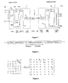
- Figure 1 shows an OFDM communication system in accordance with one embodiment of the invention comprising a transmitter comprising an OFDM modulator 1 and a receiver comprising an OFDM demodulator 2, the transmitter and the receiver communicating over a communication channel 3.
- the time domain OFDM signal is generated by means 4 which performs an Inverse Fourier Transform operation, or preferably an Inverse Fast Fourier Transform ('IFFT') operation
- ( ⁇ ) T is the transposition operator
- ( ⁇ )* is the complex conjugate operator:
- F N 1 N ⁇ W N lk 0 ⁇ l ⁇ N - 1 , 0 ⁇ k ⁇ N - 1
- W N e - j ⁇ 2 ⁇ ⁇ N .
- the series digital signal x n is then converted to an analogue signal x ( t ) by a digital-to-analogue converter 6 and transmitted over the channel 3.
- an analogue signal r ( t ) is received and converted to a digital signal r n by an analogue-to-digital converter 7.
- the digital signal r n is then converted to a parallel signal by a series-to-parallel converter r ( k ) and equalised and demodulated by equalisation and demodulation means 9 to produce demodulated signals s est ( k ).
- consideration of noise is omitted for the sake for simplicity. However, including the consideration of noise does not significantly modify the results.
- data from the end of the frame is repeated by the transmitter in the guard interval to produce a prefix.
- the prefix samples inserted as guard interval of OFDM symbol number k, ⁇ k .c 0 to ⁇ k .c D-1 are deterministic and are known to said receiver as well as to said transmitter.
- the weighting factor ⁇ k may be constant from one symbol to another.
- the weighting factor ⁇ k differs from one symbol to another, the elements of a given vector P D being multiplied by the same weighting factor.
- ⁇ k can be of any complex value.
- ⁇ k can be of any complex value.
- ⁇ 1 leads to performance degradation compared to preferred embodiments.
- ⁇ k such that its phase changes from OFDM symbol to OFDM symbol.
- P D is preferably chosen with respect to certain criteria, for example the following:
- the receiver is able to estimate the channel impulse response blindly, track the changes of the channel impulse response blindly and perform an arithmetically simple equalization.
- FIG. 2 An example of a frame of OFDM symbols in accordance with a preferred embodiment is illustrated in Figure 2 .
- the operation of the system will first be described for the specific case where ⁇ k is constant and equal to 1.
- [ H IBI ] is the contribution of the demodulator 9 channel matrix corresponding to inter-block-interference
- [ H ISI ] is its contribution to inter-symbol-interference.
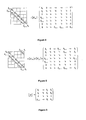
- the channel impulse response seen by demodulator 9 is represented by the sum of the inter-block-interference [ H IBI ] and the inter-symbol-interference [ H ISI ], as shown in Figure 5 .
- the resulting signal for this example is shown in Figure 9 , where r 0 ( k ) to r 4 ( k ) are successive parts of the OFDM symbol # k containing as well contributions of the preceding and following prefix convolved by the channel, x 0 ( k ) to x 3 ( k ) are corresponding parts of size D of the useful signal transmitted and x 4 ( k ) is a corresponding part of size D of the following prefix in this example.
- the example may be generalised to any N ⁇ N + , D ⁇ N + .
- the matrices [ H 0 ],[ H 1 ] and [ H ] are illustrated by Figure 8, Figure 7 and Figure 6 respectively.
- the channel impulse response is estimated using the following steps:
- the resulting channel estimation is ⁇ D of size D x1.
- This method works well in many circumstances and has a low arithmetic cost, since its calculations are based on matrices of size D x D .
- an OFDM symbol which usually is of size N > D samples will be equalized based on this estimation.
- this method works very well if the prefix-spectrum is non-zero everywhere in the FFT D ⁇ D domain (and, of course, everywhere well above channel noise). This can be a troublesome limitation in other circumstances.
- a second method of channel impulse response estimation on D carriers avoids this limitation, at the expense of increased arithmetic cost.
- This second method does not estimate ⁇ D based on a de-convolution in the FFT D ⁇ D domain as presented above, but estimates FFT N + D ⁇ N + D h ⁇ D T ⁇ 0 N T T directly based on the received vector ([ H 0 ]+[ H 1 ]) ⁇ P D .
- H N + D ⁇ N + D ⁇ P D T ⁇ 0 N T T E 4 T ⁇ E 0 T ⁇ 0 N - D T T
- the last step of the list presented above is not essential for the basic equalization algorithm but may be useful, for example in algorithms used to reduce noise levels.
- the Fourier matrix [ F ] can be chosen in the N + D carriers or D carriers domain
- a first method of equalization uses zero forcing in the N + D Domain and offers low complexity equalization.
- H H ISI + ⁇ k ⁇ k + 1 ⁇
- H 1 N + D ⁇ V - 1 ⁇ diag ⁇ H ⁇ ⁇ k - 1 N + D , H ⁇ e j ⁇ 2 ⁇ ⁇ N + D ⁇ ⁇ k - 1 N + D , ... , H ⁇ e j ⁇ 2 ⁇ ⁇ N + D ⁇ N + D - 1 ⁇ ⁇ k - 1 N + D ⁇ V ⁇ N + D .
- the Channel Impulse Response estimation obtained as described above is then used together with the known values of P D to perform the following operation
- [ H ] is a pseudo circulant channel matrix. So, the diagonalisation of such matrices can then be performed in order to calculate [ H ] ⁇ P D efficiently.
- several equalization approaches are possible, for example the Zero Forcing (ZF) approach or the Minimum Mean Square Error (MMSE) equalization approach.
- ZF Zero Forcing
- MMSE Minimum Mean Square Error
Landscapes
- Engineering & Computer Science (AREA)
- Computer Networks & Wireless Communication (AREA)
- Signal Processing (AREA)
- Power Engineering (AREA)
- Physics & Mathematics (AREA)
- Mathematical Physics (AREA)
- Cable Transmission Systems, Equalization Of Radio And Reduction Of Echo (AREA)
Description
- This invention relates to communication using Orthogonal Frequency Division Multiplexing ('OFDM') and, more particularly, to channel estimation and tracking in OFDM communication.
- OFDM communication has been chosen for most of the modern high-data rate communication systems (Digital Audio Broadcast - DAB, Terrestrial Digital Video Broadcast - DVB-T, and Broadband Radio Access Networks - BRAN such as HIPERLAN/2, IEEE802.11a, for example). However, in most cases the receiver needs an accurate estimate of the channel impulse response.
- In many known OFDM systems, each OFDM symbol of size


- Like other digital communication systems, OFDM modulation encounters problems at high Doppler spreads, which occur notably when the user is moving fast, for example in a car. HIPERLAN/2, for example, was designed to work only up to speeds of 3 m/s ("pedestrian speed"). Accordingly, the channel impulse response needs to be constantly tracked and updated, especially in the presence of high Doppler spreads.
- In a known OFDM communication system pilot tones are added which may change their position from one OFDM symbol to another. The amplitudes and positions of the pilot tones are known to the receiver. The receiver uses the pilot tones to estimate the channel coefficients of the corresponding carriers. This method is widely used, but it degrades the system performance, since a certain number of carriers cannot be used for data, since they are reserved for the pilot tones.
- It is also known to add learning sequences (See for example EBU Review Technical No. 224, August 1987, "Principles of modulation and channel coding for digital broadcasting for mobile receiver", by M. Alard and R. Lassalle.). In HIPERLAN/2, for example, there are at least 2 learning OFDM symbols per frame (i.e. 2 OFDM symbols of 2·4µs duration in total per 2ms). If the channel changes quickly, there must be many more training sequences and the consequence is an even bigger degradation in the system performance.
- Many of the known systems are unable to decode all carriers of OFDM symbols in the presence of channel nulls. Recent innovations propose ways for decoding OFDM symbols even in the presence of channel nulls (see for example the publication entitled "Reduced Complexity Equalizers for Zero-Padded OFDM transmissions" by B. Muquet, Marc de Courville, G. B. Giannakis, Z. Wang, P. Duhamel in the proceedings of the International Conference on Acoustics Speech and Signal Processing ('ICASSP') 2000 and the publication entitled "OFDM with trailing zeros versus OFDM with cyclic prefix: links, comparisons and application to the HiperLAN/2 system" by Muquet, B.; de Courville, M.; Dunamel, P.; Giannakis, G. in the proceedings of the IEEE International Conference on Communications, 2000, Volume: 2. However, these publications do not offer responses to the problems referred to above concerning channel estimation and channel tracking.
- Ideally, the OFDM modulation system would keep all the advantages of classic OFDM and additionally allow very simple and completely blind channel estimation at the receiver. No additional redundancy would be added to the system and therefore no bandwidth would be lost. Such a system would be advantageous in low-mobility scenarios and would make OFDM systems applicable to high-mobility scenarios as well.
- Many of the examples and illustrations presented below are based on the assumption N = 4 · D, that is to say that the size of the prefix (D samples) is assumed to be one quarter of the size of the useful OFDM symbol (N samples). This corresponds to the case of HiperLAN/2 or IEEE802.11. This restriction is introduced for sake of simplicity only. It will be appreciated that the examples and illustrations are applicable more generally to the case of


- The present invention provides a method of, and a transmitter and a receiver for, communication using OFDM as described in the accompanying claims 1-15. In the following, references to embodiments are to be interpreted as examples useful for understanding the invention which is solely defined by the scope of claims 1-15.
-
-
Figure 1 is a block schematic diagram of an OFDM communication system comprising a transmitter and a receiver in accordance with one embodiment of the invention, given by way of example, -
Figure 2 is a schematic diagram of an OFDM frame in a signal appearing in operation of the system ofFigure 1 , -
Figure 3 is a matrix equation representing the channel impulse response for inter-block interference in operation of the system ofFigure 1 , -
Figure 4 is a matrix equation representing the channel impulse response for inter-symbol interference in operation of the system ofFigure 1 , -
Figure 5 is a matrix equation representing the combined channel impulse response in operation of the system ofFigure 1 , -
Figure 6 is a representation of a sub-matrix corresponding to the combined channel impulse response in operation of the system ofFigure 1 for a prefix part of the signal ofFigure 2 , -
Figure 7 represents the upper triangular sub-matrix of the channel matrix presented byFigure 6 , -
Figure 8 represents the lower triangular sub-matrix of the channel matrix presented byFigure 6 , and -
Figure 9 is a matrix equation representing signals appearing as a result of the combined channel impulse response in operation of one embodiment of a system of the kind shown inFigure 1 , -
Figure 10 is a matrix equation representing signals appearing during channel estimation in operation of one embodiment of a system as shown inFigure 1 , -
Figure 11 is a matrix equation representing signals appearing as a result of the combined channel impulse response in operation of another embodiment of a system of the kind shown inFigure 1 -
Figure 12 is a graph representing preferred values of prefixes used in the system ofFigure 1 . -
Figure 1 shows an OFDM communication system in accordance with one embodiment of the invention comprising a transmitter comprising anOFDM modulator 1 and a receiver comprising anOFDM demodulator 2, the transmitter and the receiver communicating over acommunication channel 3. - An input bit-stream bn ∈ (0,1),n = 0,1,...,K -1 is modulated onto a set of N carriers whose carrier amplitudes are given by the vector X(k) = (X 0(k), X 1(k),...,X N-1(k)) T , corresponding to OFDM symbol number k. Afterwards, the time domain OFDM signal is generated by means 4 which performs an Inverse Fourier Transform operation, or preferably an Inverse Fast Fourier Transform ('IFFT') operation [FN ]-1 = [FN ] H with [FN ] H = ([FN ] T )* where (·) T is the transposition operator and (·)* is the complex conjugate operator:

where

- The resulting parallel signal x(k) vector is converted to a series signal by a parallel-to-
series converter 5, a prefix, represented by the D×1 vector PD = (c 0,...,c D-1) T , being inserted into the signal as guard interval between each OFDM symbol to produce a series digital signal xn . The series digital signal xn is then converted to an analogue signal x(t) by a digital-to-analogue converter 6 and transmitted over thechannel 3. - The
channel 3 has a Channel Impulse Response H(k) = C(k) and also introduces noise v. - At the
receiver 2, an analogue signal r(t) is received and converted to a digital signal rn by an analogue-to-digital converter 7. The digital signal rn is then converted to a parallel signal by a series-to-parallel converter r(k) and equalised and demodulated by equalisation and demodulation means 9 to produce demodulated signals sest (k). In the following analysis, consideration of noise is omitted for the sake for simplicity. However, including the consideration of noise does not significantly modify the results. - In some known OFDM communication systems, the guard interval is used to add some redundancy (D samples of redundancy are added) by introducing a cyclic prefix, for example in the following manner:

In other words, data from the end of the frame is repeated by the transmitter in the guard interval to produce a prefix. - In accordance with this embodiment, however, the prefix samples inserted as guard interval of OFDM symbol number k, α k.c0 to α k.cD-1, are deterministic and are known to said receiver as well as to said transmitter. The prefixes comprise a vector PD = (c0 ,...,cD-1 ) T of size D×1 that is common to the symbols multiplied by at least one weighting factor α k , so that the prefixes have the overall form α k.c0 to α k.cD-1. The weighting factor α k may be constant from one symbol to another. However, in a preferred embodiment, the weighting factor α k differs from one symbol to another, the elements of a given vector PD being multiplied by the same weighting factor. With an OFDM modulator in the transmitter functioning in this way, blind channel estimation in the receiver can be done simply and at low arithmetical complexity. In particular, the receiver can constantly estimate and track the channel impulse response without any loss of data bandwidth. Moreover, the demodulator at the receiver can have advantageous characteristics, ranging from very low arithmetical cost (at medium performance) to high arithmetical cost (very good system performance).
- More particularly, in the preferred embodiment, the prefix of D samples that is added in the guard interval comprises a pre-calculated suitable vector PD = (c 0,...,cD-1 ) T of D samples that is independent of the data and that is weighted by a pseudo-random factor α k that only depends on the number k of the latest OFDM symbol:

- For the purposes of the analysis below, a second prefix/OFDM symbol vector is defined as follows:

- Several choices for α k are possible. It is possible to choose

- It is possible to limit the choice of α k , somewhat less generally to

- Accordingly, in the preferred embodiment, the phase of α k is chosen so that

- For the sake of simplicity, the following analysis assumes that the weighting factor has been chosen as

- It proves to be very useful to choose α k such that its phase changes from OFDM symbol to OFDM symbol. The constant prefix PD is preferably chosen with respect to certain criteria, for example the following:
- In the frequency domain, PD is as flat as possible over the frequency band used for data carriers.
- In the frequency domain, PD is as near to zero as possible for all unused parts of the band.
- In the time domain, PD has a low peak-to-average-power-ratio (PAPR).
- The length of PD is the size of the OFDM guard interval, that is to say D samples. Alternatively, a shorter sequence of length D < D may be chosen where D - D̂ zeros are appended.
- With these criteria, without any complication of the transmitter, the receiver is able to estimate the channel impulse response blindly, track the changes of the channel impulse response blindly and perform an arithmetically simple equalization.
- An example of a frame of OFDM symbols in accordance with a preferred embodiment is illustrated in
Figure 2 . The operation of the system will first be described for the specific case where α k is constant and equal to 1. - Now, the modulation unit of the transmitter is clearly defined. In the following, the operations to be performed in the receiver are considered. Each received OFDM symbol selected at the input of the demodulator 9 can then be expressed as follows (neglecting additive noise):

where the channel impulse response of the demodulator 9 is assumed to be h = (h 0,...,h D-1), [HIBI ] is the contribution of the demodulator 9 channel matrix corresponding to inter-block-interference and [HISI ] is its contribution to inter-symbol-interference. - The components of the received signal corresponding to inter-block-interference [HIBI ]r(k-1) are illustrated in
Figure 3 , where blank elements correspond to zero values, for an example where N = 4 · D (for example, in the case of HiperLAN/2 or IEEE802.11, N = 64 and D = 16). It will be seen that [HIBI ] is a matrix of size (N+D)x(N+D) with a triangular sub-matrix [H I] of size (D-1)x(D-1) at its upper right-hand corner, illustrated byFigure 7 , the other elements of the matrix being zero. - The components of the received signal corresponding to inter-symbol-interference [HISI ]r(k) are illustrated in
Figure 4 , for the same case and in the same manner asFigure 3 . It will be seen that [HISI ] is a matrix of size (N+D)x(N+D) with triangular sub-matrices [H 0] on its major diagonal as illustrated byFigure 8 and triangular sub-matrices [H 1] of size DxD on the diagonal immediately below the main diagonal as illustrated byFigure 7 , the other elements of the matrix being zero. - The channel impulse response seen by demodulator 9 is represented by the sum of the inter-block-interference [HIBI ] and the inter-symbol-interference [HISI ], as shown in
Figure 5 . The resulting signal for this example is shown inFigure 9 , where r0 (k) to r4 (k) are successive parts of the OFDM symbol #k containing as well contributions of the preceding and following prefix convolved by the channel, x0 (k) to x 3(k) are corresponding parts of size D of the useful signal transmitted and x4 (k) is a corresponding part of size D of the following prefix in this example. Of course, the example may be generalised to any N ∈ N+, D ∈ N+. - The expectation values of the parts of the received signals are as follows:


- It will be appreciated that the expectation values of the useful parts x 0(k) to x 3(k) of the OFDM symbol tend to zero over a large number of symbols since they are quasi-random with zero mean. However, the prefix PD is known to the receiver (and in this embodiment is constant over successive symbols) and enables [H]= [H 0]+[H 1] to be estimated, by approximating the expectation values E 0 and E 4 over a large number R of symbols:

- The sum of the expectation values E 0 and E 4 is then given by:

- A first method of channel impulse response estimation on D symbols utilises the expression of the above equation as follows:

Figure 8, Figure 7 andFigure 6 respectively. - Accordingly, in this first method, the channel impulse response is estimated using the following steps:
- Perform a FFT D×D on VHP = ([H 0] + [H 1])·PD = E 0 + E 4
- Perform a FFTD×D on VP = PD
- Perform a component-by-component division of the first result by the second


- Perform an IFFT on


- The resulting channel estimation is ĥD of size Dx1. This method works well in many circumstances and has a low arithmetic cost, since its calculations are based on matrices of size DxD. However, an OFDM symbol which usually is of size N>D samples will be equalized based on this estimation. Thus, this method works very well if the prefix-spectrum is non-zero everywhere in the FFT D×D domain (and, of course, everywhere well above channel noise). This can be a troublesome limitation in other circumstances.
- A second method of channel impulse response estimation on D carriers avoids this limitation, at the expense of increased arithmetic cost. This second method does not estimate ĥD based on a de-convolution in the FFT D×D domain as presented above, but estimates


- This equation is represented in more detail in
Figure 10 . In this second method, the channel impulse response is estimated using the following steps: - Perform a FFT (N+D)×(N+D) on

- Perform a FFT (N+D)×(N+D) on

- Perform a component-by-component division

- If desired, perform an IFFT on

- The last step of the list presented above is not essential for the basic equalization algorithm but may be useful, for example in algorithms used to reduce noise levels.
- The above methods have been described with reference to the specific case where α k is constant and equal to 1. In preferred embodiments however, the weight α k of the prefix to each symbol k is a preferably complex pseudo-random factor that only depends on the number k of the latest OFDM symbol. The adaptations to this method of the basic equations (shown in
Figure 9 ) are shown inFigure 11 . - It is found that equations 4 and 8 are to be adapted as follows:


- The procedures for blind channel estimation described above remain applicable by setting E 0=E α,0 and E 4=E α,4,. This amounts to weighting the preceding and following D prefix-samples of each received symbol by the corresponding


- The values of the prefixes α k ·PD are chosen as a function of selected criteria, as mentioned above. Values that have been found to give good results with the criteria:
- Low Peak-to-Average-Power-Ratio of the time domain signal
- Low Out-of-Band Radiation, that is to say maximise the energy of the prefix over the useful band and not waste prefix energy over null carriers
- Spectral Flatness, e.g. SNR of each channel estimates shall be approx. constant
- Low-Complexity Channel Estimation, i.e. by prefix spectrum whose spectral contributions are mainly just phases (i.e. of constant modulus),
- Size of the Prefix in Time Domain: D=16 Samples
- Size of the OFDM symbols in the frame: N=64 Samples
- Carriers where channel coefficients are to be estimated (over N+D=80 carriers):
Carriers 1 to 52 - Out-of-Band region: Carriers 76 to 80
- Maximum PAPR has not been limited
- Out-of-Band Radiation as low as possible
- Spectral Flatness as good as possible.
- The channel estimation is done by calculating the expectation value over a number of samples of the received vector as explained above. If the tracking of the channel is done based on a first estimation ĥ(k-1)=[(FD ] H · Ĥ(k-1) of the channel impulse response and a number R of OFDM symbols, the first estimate is then updated as follows:


based on the ideas of the first method for channel estimation that has been presented above. Alternatively, the second method can be applied by

where the factors sn,n = 0,1,...,R -1 are positive real numbers that are used for normalization and weighting of the different contributions. Thus, for example it is possible to take older OFDM symbols less into account for the channel estimation than later ones. The Fourier matrix [F] can be chosen in the N+D carriers or D carriers domain - Several equalization methods are advantageous using the pseudo-random prefix OFDM. In general, the different methods offer different performance-complexity trade-offs.
- A first method of equalization uses zero forcing in the N+D Domain and offers low complexity equalization.
- With


- Still assuming that the length of the channel impulse response is D, the coefficients h D+1,...,h N+D-1 are set to zero. This is a so-called pseudo-circulant matrix, corresponding to the case where β k is not equal to 1, and can be diagonalized as follows:

- With the assumption that


the procedure of this method of zero forcing equalisation is: - Perform Multiplication

where
- Calculate the frequency shifted, estimated CIR coefficients

- Perform a component-by-component division

- Perform Multiplication

- Extract the N equalized samples of the kth OFDM-data symbol to SEQ (k).
- Transform the kth OFDM data symbol SEQ (k) into the frequency domain by a Fourier transform SF EQ (k)=[FN ]·SEQ (k).
- Proceed with metric calculation, etc. on the received equalised carriers.
- Another method of equalization uses a method known from studies on zero padding. The received vector R(k) in the OFDM Pseudo Random Prefix Scheme can be expressed as follows, where [P] contains a (N+D)×N precoding matrix and IN is the NxN identity matrix:

- The Channel Impulse Response estimation obtained as described above is then used together with the known values of PD to perform the following operation

in which the known prefix values are multiplied by the Channel Impulse Response estimation and the result is subtracted from the received signal. In the general case, [H] is a pseudo circulant channel matrix. So, the diagonalisation of such matrices can then be performed in order to calculate [H] · PD efficiently. Then, several equalization approaches are possible, for example the Zero Forcing (ZF) approach or the Minimum Mean Square Error (MMSE) equalization approach. Examples of MMSE equalization methods are described in the articles " OFDM with trailing zeros versus OFDM with cyclic prefix: links, comparisons and application to the HiperLANl2 system" by Muquet, B.; de Courville, M.; Dunamel, P.; Giannakis, G. ICC 2000 - IEEE International Conference on Communications, and " Reduced Complexity Equalizers for Zero-Padded OFDM transmissions" by Muquet, B.; de Courville, M.; Giannakis, G. B.; Wang, Z.; Duhamel, P. International Conference on Acoustics Speech and Signal Processing (ICASSP) 2000. - In one example, the equalisation is performed based on a zero-forcing approach by multiplying y (1) by the Moore-Penrose pseudo-inverse [G] of the


- The definition of the Moore-Penrose pseudo-inverse is, among others, discussed by Haykin in the book: " Adaptive Filter Theory" by Simon Haykin, 3rd edition, Prentice Hall Information and System Science Series, 1996. Haykin uses the common definition

Claims (15)
- A method of communication using Orthogonal Frequency Division Multiplexing, OFDM, the method comprising the steps of:generating bit streams bn ∈ (0,1),n =0,1,.., K -1 and corresponding frequency domain carrier amplitudes X 0(k) to XN (k), where k is the OFDM symbol number, modulated as OFDM symbols to be transmitted from a transmitter (1),inserting prefixes as guard intervals in said OFDM symbols,transmitting said OFDM symbols from said transmitter to a receiver (2) over transmission channel,using information from said prefixes to estimate the Channel Impulse Response
 using the estimated Channel impulse Response
 characterised in that said prefixes, denotes as, α k. c 0 to α k.c D-1 are non-zero and deterministic and are known to said receiver as well as to said transmitter, wherein α k is weighting factor of said prefixes and is proportional to
- A method of communication as claimed in claim 1, wherein said prefixes α k. c 0 to α k. c D-1 comprise said vector PD that is common to said OFDM symbols multiplied by at least said weighting factor α k .
- A method of communication as claimed in claim 2, wherein said weighting factor α k differs from one OFDM symbol to another but the elements of said vector PD are multiplied by the same weighting factor.
- A method of communication as claimed in claim 3, wherein said weighting factor α k has a pseudo-random value.
- A method of communication as claimed in claim 1, wherein said weighting factor α k is a complex value.
- A method of communication as claimed in claim 5, wherein the modulus of said weighting factor α k is constant from one OFDM symbol to another.
- A method of communication as claimed in claim 1, wherein estimating said Channel Impulse Response

- A method of communication as claimed in claim 7, wherein said prefixes comprise said vector PD that is common to said OFDM symbols multiplied by weighting factors α k , α k+1, said weighting factors differing from one OFDM symbol to another but the elements of said vector being multiplied by the same weighting factor, and wherein components of one of said received signals corresponding to said one of said prefixes α k. c 0 to α k. c D-1 and components of said received signals corresponding to one of further prefixes α k+1. c 0 to α k+1. c D-1 are weighted by the respective value of said weighting factor α k, α k+1 before performing said Fourier Transform to produce said received prefix signal transform VHP,F .
- A method of communication as claimed in claim 7, wherein said first and second Fourier Transforms are of dimension DxD, where D is the number of elements contained in said vector PD.
- A method of communication as claimed in claim 7, wherein said first and second Fourier Transforms are of dimension (D+N)x(D+N), where D is the number of elements contained in said prefix vector PD and N is the number of OFDM symbols, said first vector VHP comprises the sum of said components corresponding to one of said prefixes α k. c 0 to α k. c D-1 and one of said prefixes α k+1. c 0 to α k+1. c D-1 augmented by a zero value vector


- A method of communication as claimed in claim 1, wherein estimating said Channel Impulse Response


- A method of communication as claimed in claim 1, wherein demodulating said bit streams comprises: obtaining a received signal vector R(1)(k) by performing the multiplication:


calculating the frequency shifted CIR coefficients of said Channel Impulse Response:
performing a component-by-component division :
performing the multiplication:
extracting the N equalized samples corresponding to the kth OFDM symbol to the vector SEQ (k),
and
transforming the vector SEQ (k) into frequency domain by performing: SF EQ (k) = [FNxN ]·SEQ (k), wherein [FN+D] and [FNxN] are Fourier transform matrices of dimension (N+D)x(N+D) and NxN, respectively. - A method of communication as claimed in claim 1, wherein demodulating said bit streams includes padding a received signal matrix comprising said received signals and an operator matrix with zeros to obtain compatible dimensions for subsequent operations, multiplying a prefix value matrix comprising said prefixes by a Channel Impulse Response estimation matrix comprising coefficient of said estimated Channel Impulse Response and subtracting the multiplication result from the received signal matrix.
- A transmitter comprising means (1) for performing The steps of generating, inserting, and transmitting according to claim 1.
- A receiver comprising means (2) for performing the steps of estimating the Channel Impulse Response and demodulating the bit streams according to claim 1.
Priority Applications (1)
| Application Number | Priority Date | Filing Date | Title |
|---|---|---|---|
| EP03813028.2A EP1559252B1 (en) | 2002-10-31 | 2003-10-30 | Blind Channel Estimation, Tracking, and Equalizing for OFDM based communications |
Applications Claiming Priority (4)
| Application Number | Priority Date | Filing Date | Title |
|---|---|---|---|
| EP20020292730 EP1416689A1 (en) | 2002-10-31 | 2002-10-31 | Channel estimation using the guard interval of a multicarrier signal |
| EP02292730 | 2002-10-31 | ||
| PCT/EP2003/050767 WO2004064344A1 (en) | 2002-10-31 | 2003-10-30 | Channel estimation using the guard interval of a multicarrier signal |
| EP03813028.2A EP1559252B1 (en) | 2002-10-31 | 2003-10-30 | Blind Channel Estimation, Tracking, and Equalizing for OFDM based communications |
Publications (2)
| Publication Number | Publication Date |
|---|---|
| EP1559252A1 EP1559252A1 (en) | 2005-08-03 |
| EP1559252B1 true EP1559252B1 (en) | 2015-06-17 |
Family
ID=32088083
Family Applications (2)
| Application Number | Title | Priority Date | Filing Date |
|---|---|---|---|
| EP20020292730 Withdrawn EP1416689A1 (en) | 2002-10-31 | 2002-10-31 | Channel estimation using the guard interval of a multicarrier signal |
| EP03813028.2A Expired - Lifetime EP1559252B1 (en) | 2002-10-31 | 2003-10-30 | Blind Channel Estimation, Tracking, and Equalizing for OFDM based communications |
Family Applications Before (1)
| Application Number | Title | Priority Date | Filing Date |
|---|---|---|---|
| EP20020292730 Withdrawn EP1416689A1 (en) | 2002-10-31 | 2002-10-31 | Channel estimation using the guard interval of a multicarrier signal |
Country Status (7)
| Country | Link |
|---|---|
| US (1) | US7450490B2 (en) |
| EP (2) | EP1416689A1 (en) |
| JP (1) | JP4125722B2 (en) |
| KR (1) | KR100861672B1 (en) |
| CN (1) | CN1708965A (en) |
| AU (1) | AU2003303109A1 (en) |
| WO (1) | WO2004064344A1 (en) |
Families Citing this family (9)
| Publication number | Priority date | Publication date | Assignee | Title |
|---|---|---|---|---|
| US7400573B2 (en) * | 2003-04-29 | 2008-07-15 | Intel Corporation | Dynamic allocation of cyclic extension in orthogonal frequency division multiplexing systems |
| JP2005191997A (en) * | 2003-12-26 | 2005-07-14 | Sanyo Electric Co Ltd | Receiving method and apparatus thereof |
| US8149685B2 (en) * | 2004-09-03 | 2012-04-03 | University Of South Florida | Covert OFDM transmission using cyclic prefix |
| DE102004045075B4 (en) * | 2004-09-15 | 2015-06-03 | IAD Gesellschaft für Informatik, Automatisierung und Datenverarbeitung mbH | Method and device for recessing adjustable narrow frequency bands in a broadband transmission signal |
| US20060159187A1 (en) * | 2005-01-14 | 2006-07-20 | Haifeng Wang | System and method for utilizing different known guard intervals in single/multiple carrier communication systems |
| US7551547B2 (en) * | 2005-01-28 | 2009-06-23 | At&T Intellectual Property I, L.P. | Delay restricted channel estimation for multi-carrier systems |
| US7813383B2 (en) * | 2005-03-10 | 2010-10-12 | Qualcomm Incorporated | Method for transmission of time division multiplexed pilot symbols to aid channel estimation, time synchronization, and AGC bootstrapping in a multicast wireless system |
| US7929620B2 (en) | 2005-12-08 | 2011-04-19 | Electronics And Telecommunications Research Institute | Blind channel estimation in an orthogonal frequency division multiplexing system |
| US8315151B2 (en) * | 2006-01-18 | 2012-11-20 | St-Ericsson Sa | Radio communication system |
Family Cites Families (7)
| Publication number | Priority date | Publication date | Assignee | Title |
|---|---|---|---|---|
| US5113444A (en) * | 1990-09-05 | 1992-05-12 | Arnold Vobach | Random choice cipher system and method |
| US5495432A (en) * | 1994-01-03 | 1996-02-27 | Industrial Technology Research Institute | Apparatus and method for sampling rate conversion |
| US6144711A (en) * | 1996-08-29 | 2000-11-07 | Cisco Systems, Inc. | Spatio-temporal processing for communication |
| US7027464B1 (en) | 1999-07-30 | 2006-04-11 | Matsushita Electric Industrial Co., Ltd. | OFDM signal transmission scheme, and OFDM signal transmitter/receiver |
| US20020048333A1 (en) * | 2000-05-25 | 2002-04-25 | Nadeem Ahmed | Joint detection in OFDM systems |
| US9130810B2 (en) * | 2000-09-13 | 2015-09-08 | Qualcomm Incorporated | OFDM communications methods and apparatus |
| US6369758B1 (en) * | 2000-11-01 | 2002-04-09 | Unique Broadband Systems, Inc. | Adaptive antenna array for mobile communication |
-
2002
- 2002-10-31 EP EP20020292730 patent/EP1416689A1/en not_active Withdrawn
-
2003
- 2003-10-30 KR KR1020057007688A patent/KR100861672B1/en active IP Right Grant
- 2003-10-30 CN CNA2003801024817A patent/CN1708965A/en active Pending
- 2003-10-30 JP JP2004566049A patent/JP4125722B2/en not_active Expired - Fee Related
- 2003-10-30 WO PCT/EP2003/050767 patent/WO2004064344A1/en active Application Filing
- 2003-10-30 EP EP03813028.2A patent/EP1559252B1/en not_active Expired - Lifetime
- 2003-10-30 AU AU2003303109A patent/AU2003303109A1/en not_active Abandoned
- 2003-10-30 US US10/531,785 patent/US7450490B2/en not_active Expired - Fee Related
Also Published As
| Publication number | Publication date |
|---|---|
| KR100861672B1 (en) | 2008-10-07 |
| WO2004064344A1 (en) | 2004-07-29 |
| JP2006506921A (en) | 2006-02-23 |
| AU2003303109A1 (en) | 2004-08-10 |
| CN1708965A (en) | 2005-12-14 |
| US7450490B2 (en) | 2008-11-11 |
| KR20050071651A (en) | 2005-07-07 |
| EP1559252A1 (en) | 2005-08-03 |
| JP4125722B2 (en) | 2008-07-30 |
| US20060120275A1 (en) | 2006-06-08 |
| EP1416689A1 (en) | 2004-05-06 |
Similar Documents
| Publication | Publication Date | Title |
|---|---|---|
| EP1511210B1 (en) | OFDM channel estimation and tracking for multiple transmit antennas | |
| EP1512258B1 (en) | Apparatus and method for estimating a channel in a multiple input transmission system | |
| US8351553B2 (en) | MIMO receiving apparatus and receiving method | |
| EP1949632B1 (en) | Methods and apparatus for mitigation of nonlinear distortion | |
| EP1861972B1 (en) | Channel estimation optimization | |
| EP1171983B1 (en) | Multicarrier receiver with channel estimator | |
| US6990153B1 (en) | Method and apparatus for semi-blind communication channel estimation | |
| EP2002622A1 (en) | Channel estimation for rapid dispersive fading channels | |
| EP1842305A2 (en) | Delay restricted channel estimation for multi-carrier systems | |
| EP2420033B1 (en) | Method and receiver for jointly decoding received communication signals using maximum likelihood detection | |
| EP2192735A1 (en) | Receiving apparatus and method for receiving signals in a wireless communication system with improved equalization performance | |
| Ehsanfar et al. | Interference-free pilots insertion for MIMO-GFDM channel estimation | |
| EP1335518A1 (en) | Reception of multicarrier spread-spectrum signals | |
| US20070133393A1 (en) | Multi-carrier receiving method and multi-carrier receiving apparatus | |
| EP1901505A2 (en) | Wireless communication apparatus | |
| JP3910956B2 (en) | Propagation path estimator and receiving apparatus using the same for OFDM wireless communication system | |
| EP1559252B1 (en) | Blind Channel Estimation, Tracking, and Equalizing for OFDM based communications | |
| CN115699690A (en) | Generalized orthogonal linear frequency modulated waveform | |
| US20060017613A1 (en) | High doppler channel estimation for OFD multiple antenna systems | |
| EP1629649B1 (en) | Apparatus and method for precoding a multicarrier signal | |
| Patra et al. | A novel LMMSE-EM channel estimator for high mobility STBC-OFDM system | |
| Zemen et al. | Improved channel estimation for iterative receivers | |
| Haghighi et al. | Effects of side information on complexity reduction in superimposed pilot channel estimation in OFDM systems | |
| Patra et al. | Efficient signal detection methods for high mobility OFDM system with transmit diversity | |
| Ribeiro et al. | An OFDM Symbol Design for Reduced Complexity MMSE Channel Estimation. |
Legal Events
| Date | Code | Title | Description |
|---|---|---|---|
| PUAI | Public reference made under article 153(3) epc to a published international application that has entered the european phase |
Free format text: ORIGINAL CODE: 0009012 |
|
| 17P | Request for examination filed |
Effective date: 20050531 |
|
| AK | Designated contracting states |
Kind code of ref document: A1 Designated state(s): AT BE BG CH CY CZ DE DK EE ES FI FR GB GR HU IE IT LI LU MC NL PT RO SE SI SK TR |
|
| AX | Request for extension of the european patent |
Extension state: AL LT LV MK |
|
| DAX | Request for extension of the european patent (deleted) | ||
| RIN1 | Information on inventor provided before grant (corrected) |
Inventor name: DE COURVILLE, MARC Inventor name: DEBBAH, MEROUANE Inventor name: MUCK, MARKUS |
|
| RIN1 | Information on inventor provided before grant (corrected) |
Inventor name: MUCK, MARKUS Inventor name: DEBBAH, MEROUANE Inventor name: DE COURVILLE, MARC |
|
| 17Q | First examination report despatched |
Effective date: 20091208 |
|
| RAP1 | Party data changed (applicant data changed or rights of an application transferred) |
Owner name: MOTOROLA MOBILITY, INC. |
|
| RAP1 | Party data changed (applicant data changed or rights of an application transferred) |
Owner name: MOTOROLA MOBILITY LLC |
|
| GRAP | Despatch of communication of intention to grant a patent |
Free format text: ORIGINAL CODE: EPIDOSNIGR1 |
|
| INTG | Intention to grant announced |
Effective date: 20150105 |
|
| GRAS | Grant fee paid |
Free format text: ORIGINAL CODE: EPIDOSNIGR3 |
|
| GRAA | (expected) grant |
Free format text: ORIGINAL CODE: 0009210 |
|
| AK | Designated contracting states |
Kind code of ref document: B1 Designated state(s): AT BE BG CH CY CZ DE DK EE ES FI FR GB GR HU IE IT LI LU MC NL PT RO SE SI SK TR |
|
| REG | Reference to a national code |
Ref country code: GB Ref legal event code: FG4D |
|
| REG | Reference to a national code |
Ref country code: DE Ref legal event code: R081 Ref document number: 60347721 Country of ref document: DE Owner name: GOOGLE TECHNOLOGY HOLDINGS LLC, MOUNTAIN VIEW, US Free format text: FORMER OWNER: MOTOROLA, INC., SCHAUMBURG, ILL., US |
|
| REG | Reference to a national code |
Ref country code: CH Ref legal event code: EP |
|
| REG | Reference to a national code |
Ref country code: AT Ref legal event code: REF Ref document number: 732425 Country of ref document: AT Kind code of ref document: T Effective date: 20150715 |
|
| REG | Reference to a national code |
Ref country code: IE Ref legal event code: FG4D |
|
| REG | Reference to a national code |
Ref country code: DE Ref legal event code: R096 Ref document number: 60347721 Country of ref document: DE |
|
| REG | Reference to a national code |
Ref country code: FR Ref legal event code: PLFP Year of fee payment: 13 |
|
| PG25 | Lapsed in a contracting state [announced via postgrant information from national office to epo] |
Ref country code: FI Free format text: LAPSE BECAUSE OF FAILURE TO SUBMIT A TRANSLATION OF THE DESCRIPTION OR TO PAY THE FEE WITHIN THE PRESCRIBED TIME-LIMIT Effective date: 20150617 |
|
| REG | Reference to a national code |
Ref country code: AT Ref legal event code: MK05 Ref document number: 732425 Country of ref document: AT Kind code of ref document: T Effective date: 20150617 |
|
| REG | Reference to a national code |
Ref country code: NL Ref legal event code: MP Effective date: 20150617 |
|
| PG25 | Lapsed in a contracting state [announced via postgrant information from national office to epo] |
Ref country code: BG Free format text: LAPSE BECAUSE OF FAILURE TO SUBMIT A TRANSLATION OF THE DESCRIPTION OR TO PAY THE FEE WITHIN THE PRESCRIBED TIME-LIMIT Effective date: 20150917 Ref country code: GR Free format text: LAPSE BECAUSE OF FAILURE TO SUBMIT A TRANSLATION OF THE DESCRIPTION OR TO PAY THE FEE WITHIN THE PRESCRIBED TIME-LIMIT Effective date: 20150918 |
|
| PG25 | Lapsed in a contracting state [announced via postgrant information from national office to epo] |
Ref country code: EE Free format text: LAPSE BECAUSE OF FAILURE TO SUBMIT A TRANSLATION OF THE DESCRIPTION OR TO PAY THE FEE WITHIN THE PRESCRIBED TIME-LIMIT Effective date: 20150617 |
|
| PG25 | Lapsed in a contracting state [announced via postgrant information from national office to epo] |
Ref country code: AT Free format text: LAPSE BECAUSE OF FAILURE TO SUBMIT A TRANSLATION OF THE DESCRIPTION OR TO PAY THE FEE WITHIN THE PRESCRIBED TIME-LIMIT Effective date: 20150617 Ref country code: RO Free format text: LAPSE BECAUSE OF NON-PAYMENT OF DUE FEES Effective date: 20150617 Ref country code: CZ Free format text: LAPSE BECAUSE OF FAILURE TO SUBMIT A TRANSLATION OF THE DESCRIPTION OR TO PAY THE FEE WITHIN THE PRESCRIBED TIME-LIMIT Effective date: 20150617 Ref country code: SK Free format text: LAPSE BECAUSE OF FAILURE TO SUBMIT A TRANSLATION OF THE DESCRIPTION OR TO PAY THE FEE WITHIN THE PRESCRIBED TIME-LIMIT Effective date: 20150617 Ref country code: PT Free format text: LAPSE BECAUSE OF FAILURE TO SUBMIT A TRANSLATION OF THE DESCRIPTION OR TO PAY THE FEE WITHIN THE PRESCRIBED TIME-LIMIT Effective date: 20151019 Ref country code: ES Free format text: LAPSE BECAUSE OF FAILURE TO SUBMIT A TRANSLATION OF THE DESCRIPTION OR TO PAY THE FEE WITHIN THE PRESCRIBED TIME-LIMIT Effective date: 20150617 |
|
| REG | Reference to a national code |
Ref country code: DE Ref legal event code: R097 Ref document number: 60347721 Country of ref document: DE |
|
| PLBE | No opposition filed within time limit |
Free format text: ORIGINAL CODE: 0009261 |
|
| STAA | Information on the status of an ep patent application or granted ep patent |
Free format text: STATUS: NO OPPOSITION FILED WITHIN TIME LIMIT |
|
| RAP2 | Party data changed (patent owner data changed or rights of a patent transferred) |
Owner name: GOOGLE TECHNOLOGY HOLDINGS LLC |
|
| PG25 | Lapsed in a contracting state [announced via postgrant information from national office to epo] |
Ref country code: DK Free format text: LAPSE BECAUSE OF FAILURE TO SUBMIT A TRANSLATION OF THE DESCRIPTION OR TO PAY THE FEE WITHIN THE PRESCRIBED TIME-LIMIT Effective date: 20150617 Ref country code: IT Free format text: LAPSE BECAUSE OF FAILURE TO SUBMIT A TRANSLATION OF THE DESCRIPTION OR TO PAY THE FEE WITHIN THE PRESCRIBED TIME-LIMIT Effective date: 20150617 |
|
| 26N | No opposition filed |
Effective date: 20160318 |
|
| PG25 | Lapsed in a contracting state [announced via postgrant information from national office to epo] |
Ref country code: LU Free format text: LAPSE BECAUSE OF FAILURE TO SUBMIT A TRANSLATION OF THE DESCRIPTION OR TO PAY THE FEE WITHIN THE PRESCRIBED TIME-LIMIT Effective date: 20151030 |
|
| REG | Reference to a national code |
Ref country code: CH Ref legal event code: PL |
|
| PG25 | Lapsed in a contracting state [announced via postgrant information from national office to epo] |
Ref country code: MC Free format text: LAPSE BECAUSE OF FAILURE TO SUBMIT A TRANSLATION OF THE DESCRIPTION OR TO PAY THE FEE WITHIN THE PRESCRIBED TIME-LIMIT Effective date: 20150617 |
|
| REG | Reference to a national code |
Ref country code: IE Ref legal event code: MM4A |
|
| PG25 | Lapsed in a contracting state [announced via postgrant information from national office to epo] |
Ref country code: LI Free format text: LAPSE BECAUSE OF NON-PAYMENT OF DUE FEES Effective date: 20151031 Ref country code: CH Free format text: LAPSE BECAUSE OF NON-PAYMENT OF DUE FEES Effective date: 20151031 |
|
| PG25 | Lapsed in a contracting state [announced via postgrant information from national office to epo] |
Ref country code: SI Free format text: LAPSE BECAUSE OF FAILURE TO SUBMIT A TRANSLATION OF THE DESCRIPTION OR TO PAY THE FEE WITHIN THE PRESCRIBED TIME-LIMIT Effective date: 20150617 |
|
| REG | Reference to a national code |
Ref country code: FR Ref legal event code: PLFP Year of fee payment: 14 |
|
| PG25 | Lapsed in a contracting state [announced via postgrant information from national office to epo] |
Ref country code: IE Free format text: LAPSE BECAUSE OF NON-PAYMENT OF DUE FEES Effective date: 20151030 |
|
| PG25 | Lapsed in a contracting state [announced via postgrant information from national office to epo] |
Ref country code: BE Free format text: LAPSE BECAUSE OF FAILURE TO SUBMIT A TRANSLATION OF THE DESCRIPTION OR TO PAY THE FEE WITHIN THE PRESCRIBED TIME-LIMIT Effective date: 20150617 |
|
| PG25 | Lapsed in a contracting state [announced via postgrant information from national office to epo] |
Ref country code: HU Free format text: LAPSE BECAUSE OF FAILURE TO SUBMIT A TRANSLATION OF THE DESCRIPTION OR TO PAY THE FEE WITHIN THE PRESCRIBED TIME-LIMIT; INVALID AB INITIO Effective date: 20031030 |
|
| PG25 | Lapsed in a contracting state [announced via postgrant information from national office to epo] |
Ref country code: CY Free format text: LAPSE BECAUSE OF FAILURE TO SUBMIT A TRANSLATION OF THE DESCRIPTION OR TO PAY THE FEE WITHIN THE PRESCRIBED TIME-LIMIT Effective date: 20150617 Ref country code: NL Free format text: LAPSE BECAUSE OF FAILURE TO SUBMIT A TRANSLATION OF THE DESCRIPTION OR TO PAY THE FEE WITHIN THE PRESCRIBED TIME-LIMIT Effective date: 20150617 Ref country code: SE Free format text: LAPSE BECAUSE OF FAILURE TO SUBMIT A TRANSLATION OF THE DESCRIPTION OR TO PAY THE FEE WITHIN THE PRESCRIBED TIME-LIMIT Effective date: 20150617 |
|
| PG25 | Lapsed in a contracting state [announced via postgrant information from national office to epo] |
Ref country code: TR Free format text: LAPSE BECAUSE OF FAILURE TO SUBMIT A TRANSLATION OF THE DESCRIPTION OR TO PAY THE FEE WITHIN THE PRESCRIBED TIME-LIMIT Effective date: 20150617 |
|
| REG | Reference to a national code |
Ref country code: GB Ref legal event code: 732E Free format text: REGISTERED BETWEEN 20170831 AND 20170906 |
|
| REG | Reference to a national code |
Ref country code: FR Ref legal event code: PLFP Year of fee payment: 15 |
|
| REG | Reference to a national code |
Ref country code: DE Ref legal event code: R082 Ref document number: 60347721 Country of ref document: DE Representative=s name: BETTEN & RESCH PATENT- UND RECHTSANWAELTE PART, DE Ref country code: DE Ref legal event code: R081 Ref document number: 60347721 Country of ref document: DE Owner name: GOOGLE TECHNOLOGY HOLDINGS LLC, MOUNTAIN VIEW, US Free format text: FORMER OWNER: MOTOROLA MOBILITY LLC, LIBERTYVILLE, ILL., US |
|
| REG | Reference to a national code |
Ref country code: FR Ref legal event code: PLFP Year of fee payment: 16 |
|
| PGFP | Annual fee paid to national office [announced via postgrant information from national office to epo] |
Ref country code: FR Payment date: 20201026 Year of fee payment: 18 |
|
| PG25 | Lapsed in a contracting state [announced via postgrant information from national office to epo] |
Ref country code: FR Free format text: LAPSE BECAUSE OF NON-PAYMENT OF DUE FEES Effective date: 20211031 |
|
| PGFP | Annual fee paid to national office [announced via postgrant information from national office to epo] |
Ref country code: GB Payment date: 20221027 Year of fee payment: 20 Ref country code: DE Payment date: 20221027 Year of fee payment: 20 |
|
| REG | Reference to a national code |
Ref country code: DE Ref legal event code: R071 Ref document number: 60347721 Country of ref document: DE |
|
| REG | Reference to a national code |
Ref country code: GB Ref legal event code: PE20 Expiry date: 20231029 |
|
| PG25 | Lapsed in a contracting state [announced via postgrant information from national office to epo] |
Ref country code: GB Free format text: LAPSE BECAUSE OF EXPIRATION OF PROTECTION Effective date: 20231029 |
|
| PG25 | Lapsed in a contracting state [announced via postgrant information from national office to epo] |
Ref country code: GB Free format text: LAPSE BECAUSE OF EXPIRATION OF PROTECTION Effective date: 20231029 |