EP1557646B1 - Rotary encoder and method for scanning the code disk of a rotary encoder - Google Patents
Rotary encoder and method for scanning the code disk of a rotary encoder Download PDFInfo
- Publication number
- EP1557646B1 EP1557646B1 EP04030902A EP04030902A EP1557646B1 EP 1557646 B1 EP1557646 B1 EP 1557646B1 EP 04030902 A EP04030902 A EP 04030902A EP 04030902 A EP04030902 A EP 04030902A EP 1557646 B1 EP1557646 B1 EP 1557646B1
- Authority
- EP
- European Patent Office
- Prior art keywords
- code
- analog
- angle
- track
- rotary encoder
- Prior art date
- Legal status (The legal status is an assumption and is not a legal conclusion. Google has not performed a legal analysis and makes no representation as to the accuracy of the status listed.)
- Expired - Fee Related
Links
Images


Classifications
-
- G—PHYSICS
- G01—MEASURING; TESTING
- G01D—MEASURING NOT SPECIALLY ADAPTED FOR A SPECIFIC VARIABLE; ARRANGEMENTS FOR MEASURING TWO OR MORE VARIABLES NOT COVERED IN A SINGLE OTHER SUBCLASS; TARIFF METERING APPARATUS; MEASURING OR TESTING NOT OTHERWISE PROVIDED FOR
- G01D5/00—Mechanical means for transferring the output of a sensing member; Means for converting the output of a sensing member to another variable where the form or nature of the sensing member does not constrain the means for converting; Transducers not specially adapted for a specific variable
- G01D5/12—Mechanical means for transferring the output of a sensing member; Means for converting the output of a sensing member to another variable where the form or nature of the sensing member does not constrain the means for converting; Transducers not specially adapted for a specific variable using electric or magnetic means
- G01D5/244—Mechanical means for transferring the output of a sensing member; Means for converting the output of a sensing member to another variable where the form or nature of the sensing member does not constrain the means for converting; Transducers not specially adapted for a specific variable using electric or magnetic means influencing characteristics of pulses or pulse trains; generating pulses or pulse trains
- G01D5/24471—Error correction
- G01D5/24476—Signal processing
Definitions
- the invention relates to a method for scanning a code disk of a rotary encoder according to the preamble of claim 1.
- Absolute encoders are also known which are based on a purely analog scanning of a code disk (see, for example, US Pat DE 101 43 662 ).
- these angle encoders have the disadvantage that the analog track must be made very accurately over a relatively long distance.
- the drive range of such encoders is limited, and the required accuracy of the downstream analog-to-digital converters is relatively high.
- a rotary encoder is known in which a series of gray code tracks is used and which achieves a refined angular accuracy by means of a sawtooth-shaped analog track.
- This arrangement has the disadvantage that it produces the same brightness at the discontinuities of the sawtooth as in the middle of a tooth. This gives an ambiguity of the angle to be read. Furthermore, it is not protected against damage to the code tracks.
- a goniometer having a plurality of gray coded digital tracks and an analog track continuously increasing or decreasing in synchronism therewith.
- the scanning is carried out by means of a regular arrangement of a plurality of light sensors whose distance from each other is significantly smaller than the analog gauge.
- This arrangement has the disadvantage that the achievable resolution improvement is limited by the number of light sensors attributable to the analog track width. With a relatively high demanded improvement in accuracy, this technique only becomes attractive when the required light sensor array decreases significantly. Alternatively, the width of the analog track would have to be increased, which can lead to illumination problems and also at the expense of space.
- a further disadvantage of the arrangement described is that, with maximum utilization of the angular interval available for the resolution enhancement (between two digital code jumps), it requires a second, similar and out-of-phase track in order to avoid ambiguities in the samples.
- the invention is based on the object to provide a method for scanning a code disk of a rotary encoder, which can achieve the highest possible accuracy using as few code tracks as possible and in which the demands on the manufacturing accuracy are reduced as much as possible.
- This object is achieved by a method for scanning a code disc of a rotary encoder, with a digital coding, by means of which a current angular interval can be determined from a plurality of possible angular intervals, and an analog coding, by means of the exact angular position of the code disc within the current angular interval can be determined, wherein the analog coding has successively maxima and minima, wherein the analog coding is sampled and a found maximum or minimum sample is stored as an analog reference for the respective associated angular interval in a downstream processing system and the exact angle between a maximum and a adjacent minimum in the angular interval thereafter determined by interpolation.
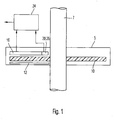
- FIG. 1 a rotary encoder 5 is shown, which is part of a steering angle sensor.
- the steering angle sensor serves to determine the angular position of a schematically indicated steering shaft 7.
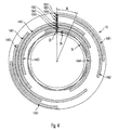
- the rotary encoder has a code disk 10 (see also FIG. 2 ), which is non-rotatably connected to the steering shaft 7.
- the code disk 10 is made of plastic and is made transparent in the embodiment shown.
- On the code disc different code tracks are arranged, which allow two types of angle determination, namely on the one hand a distinction of different angular intervals W and on the other hand, an angle determination within one of these angular intervals (see also FIG. 3 ).
- the code tracks are illuminated by a schematically shown light source 12.
- each code track 14 provides digital information to a light sensor 16 assigned to it, for example passage of light or light absorption or else light reflection or light absorption.
- the coding of the code tracks 14 can thus consist of a light-absorbing material or of a reflective material.
- the code disk 10 is divided into 16 angular intervals W and has six digital code tracks 14. It is obvious that a higher number of angular intervals W could be used.
- an analog code track 18 is provided in addition to the digital code tracks 14.
- analog means that the information readable by this code track can take a variety of discrete values.
- the analog code track 18 changes continuously within an angular interval W.
- a code track 18 is used whose width increases continuously linearly in an angular interval W and again decreases linearly from the change to the next angular interval W again.
- the analog code track 18 is scanned by a light sensor 20.
- the analog code track 18 is made opaque or translucent.
- Each found maximum (or minimum) sample of the analog code track 18 is stored as an analog reference for the respective associated angular interval W in a downstream processing system 24.
- the exact angle between a maximum and an adjacent minimum in the angular interval W is then determined by interpolation.
- the maximum or minimum samples of the analog code track 18 can be regularly updated during operation of the rotary encoder. This constantly recalibrated method ensures that the aging of the components involved plays only a minor role.
- the demands on the linearity of the analog track in the relatively small area limited within an angular interval W.
- the requirements for the accuracy of the downstream analog / digital converter are also limited to the division of the angular interval W in the desired angular accuracy.
- the analog track 18 is scanned to protect against analog track defects with another, offset from the first sensor 20 by an angle sensor 26.
- This angle is preferably half of the angular interval W plus an integer multiple of this angular interval. Since only certain sample pairs of the sensors 20, 26 are permissible for each angle in the angular interval W, damage to the analog track can therefore be reliably detected.
- the current angular interval can thus be distinguished from the adjacent angular interval even without digital track information. Thus even those damage to the digital track can be seen, which produce an angular error in the size of an angular interval.
- FIG. 4 shows a code plate 10 and its associated light sensors 16A1 to 16A4 and 16B1 and 16B2 for a rotary encoder according to a second embodiment, this only for the explanation of in FIG. 5 shown code disk and its associated sensors is used.
- the code disk 10 according to FIG. 4 is again divided into 16 angular intervals W and has as well as the code plate 10 from FIG. 2 six digital code tracks 14A1 to 14A4 and 14B1 and 14B2, which are present in an alternative arrangement, in turn, each progressing angle interval W each exactly one track changes state. Otherwise, the code disk 10 with the in the FIG. 2 shown code plate identical and can be used identically to determine the exact angular position of a steering shaft. How out FIG.
- the one labeled 14B2 will be off two-section code track is in the same position as the two-section code track designated 14B1 after the entire code track 14B2 has been rotated by an angular interval in the counterclockwise direction.
- a further reduction of the installation space is possible by the code tracks designated 14A1 to 14A4 also shifted relative to each other and summarized after these phase shifts to a single code track 14A, also at the same time a corresponding shift of the code tracks associated sensors 16A1 to 16A4 is made.
- the thus-reduced coded disc code disc 10 including the associated sensors 16A1 to 16A4 and 16B1 and 16B2 is shown in FIG FIG. 5 shown. This offers the advantage of a greatly reduced installation space while retaining the fault-tolerance of the in FIG. 2 shown code disk and a significant reduction in manufacturing costs.
Landscapes
- Engineering & Computer Science (AREA)
- Signal Processing (AREA)
- Physics & Mathematics (AREA)
- General Physics & Mathematics (AREA)
- Optical Transform (AREA)
- Transmission And Conversion Of Sensor Element Output (AREA)
- Length Measuring Devices By Optical Means (AREA)
Description
Die Erfindung betrifft ein Verfahren zum Abtasten einer Codescheibe eines Drehwinkelgebers gemäß dem Oberbegriff des Anspruchs 1.The invention relates to a method for scanning a code disk of a rotary encoder according to the preamble of claim 1.
Aus dem Stand der Technik sind verschiedene absolut arbeitende optische Winkelgeber bekannt, die auf dem durchleuchtenden oder reflektierenden Abtasten einer Codescheibe mit digitalen Spuren basieren (siehe beispielsweise die
Zur Absicherung solcher Drehgeber gegen eventuell auftretende Defekte wie beispielsweise eine beschädigte Codescheibe werden weitere Maßnahmen notwendig. Ein Ansatz besteht darin, die benötigten Spuren zur Absicherung doppelt auszuführen. Diese Maßnahmen verschärfen aber das Lichtmengenproblem zusätzlich. Die rein digitalen Sensoren haben außerdem den Nachteil, daß die Aufbringung der Codes für alle Spuren gleichermaßen genau ausgeführt werden muß.To protect such encoders against any defects such as a damaged code disc further action is necessary. One approach is to duplicate the required traces for backup. But these measures aggravate this Additional light quantity problem. The purely digital sensors also have the disadvantage that the application of the codes must be performed equally well for all tracks.
Es sind auch absolute Winkelgeber bekannt, die auf einem rein analogen Abtasten einer Codescheibe basieren (siehe beispielsweise die
Aus der
Aus der
Aus der
Der Erfindung liegt die Aufgabe zu Grunde, ein Verfahren zur Abtastung einer Codescheibe eines Drehgebers zu schaffen, der bzw. das unter Verwendung möglichst weniger Codespuren eine möglichst hohe Genauigkeit erreichen kann und bei dem die Anforderungen an die Herstellgenauigkeit so weit wie möglich reduziert sind.The invention is based on the object to provide a method for scanning a code disk of a rotary encoder, which can achieve the highest possible accuracy using as few code tracks as possible and in which the demands on the manufacturing accuracy are reduced as much as possible.
Diese Aufgabe wird gelöst durch ein Verfahren zum Abtasten eine Codescheibe eines Drehwinkelgebers, mit einer digitalen Codierung, mittels der ein aktuelles Winkelintervall aus einer Vielzahl von möglichen Winkelintervallen bestimmt werden kann, und einer analogen Codierung, mittels der die genaue Winkelposition der Codescheibe innerhalb des aktuellen Winkelintervalls bestimmt werden kann, wobei die analoge Codierung aufeinanderfolgend Maxima und Minima aufweist, wobei die analoge Codierung abgetastet wird und ein gefundener maximaler bzw. minimaler Abtastwert als Analogreferenz für das jeweilige zugeordnete Winkelintervall in einem nachgeschalteten Verarbeitungssystem abgespeichert wird und der genaue Winkel zwischen einem Maximum und einem benachbarten Minimum im Winkelintervall danach durch Interpolation ermittelt wird.This object is achieved by a method for scanning a code disc of a rotary encoder, with a digital coding, by means of which a current angular interval can be determined from a plurality of possible angular intervals, and an analog coding, by means of the exact angular position of the code disc within the current angular interval can be determined, wherein the analog coding has successively maxima and minima, wherein the analog coding is sampled and a found maximum or minimum sample is stored as an analog reference for the respective associated angular interval in a downstream processing system and the exact angle between a maximum and a adjacent minimum in the angular interval thereafter determined by interpolation.
Die Erfindung wird nachfolgend anhand mehrerer Ausführungsformen beschrieben, die in den beigefügten Zeichnungen dargestellt sind. In diesen zeigen:
-
Figur 1 einen Querschnitt durch einen Drehwinkelgeber; -
Figur 2 eine schematische Draufsicht auf eine Codescheibe und zugeordnete Lichtsensoren gemäß einer ersten Ausführungsform, die beim Drehwinkelgeber vonFigur 1 verwendet werden können; -
Figur 3 schematisch den Ablauf einer Winkelbestimmung; -
Figur 4 eine schematische Draufsicht auf eine Codescheibe und zugeordnete Lichtsensoren gemäß einer zweiten Ausführungsform, die der Erläuterung derFigur 5 -
Figur 5
-
FIG. 1 a cross section through a rotary encoder; -
FIG. 2 a schematic plan view of a code disc and associated light sensors according to a first embodiment, which in the rotary encoder ofFIG. 1 can be used; -
FIG. 3 schematically the course of an angle determination; -
FIG. 4 a schematic plan view of a code disk and associated light sensors according to a second embodiment, the explanation of theFIG. 5 is used; and -
FIG. 5 a schematic plan view of a code disk and associated light sensors according to a third embodiment.
In
Der Drehwinkelgeber weist eine Codescheibe 10 auf (siehe auch
Zur Unterscheidung zwischen verschiedenen Winkelintervallen W sind mehrere Reihen von digitalen Codespuren 14 vorgesehen. "Digital" bedeutet hier, daß jede Codespur 14 einem ihr zugeordneten Lichtsensor 16 eine digitale Information liefert, beispielsweise Lichtdurchgang oder Lichtabsorption oder auch Lichtreflexion oder Lichtabsorption. Die Codierung der Codespuren 14 kann also aus einem lichtabsorbierenden Material bestehen oder auch aus einem reflektierenden Material. Bei dem gezeigten Ausführungsbeispiel ist die Codescheibe 10 in 16 Winkelintervalle W unterteilt und weist sechs digitale Codespuren 14 auf. Es ist offensichtlich, daß auch eine höhere Anzahl von Winkelintervallen W verwendet werden könnte.To distinguish between different angular intervals W several rows of
Aus Gründen der Fehlersicherheit wird eine spezielle Anordnung der digitalen Codespuren 14 verwendet, bei dem je fortschreitender Winkelposition jeweils genau eine Spur ihren Zustand wechselt. Daher führt ein Einfachfehler (d. h. eine Beschädigung einer Codespur in einer beliebigen Winkelposition) höchstens zur Ausgabe eines Winkelfehlers in der Größe eines Winkelintervalls. Andere Defekte als ein Einfachfehler werden direkt als auf der Scheibe nicht vorkommender Code erkannt. Dies erlaubt, auf eine Verdopplung der Codespuren zur Absicherung gegen Defekte zu verzichten.For reasons of fault tolerance, a special arrangement of the
Zur Feststellung der genauen Winkelposition innerhalb eines Winkelintervalls W ist zusätzlich zu den digitalen Codespuren 14 eine analoge Codespur 18 vorgesehen. "Analog" bedeutet hier, daß die von dieser Codespur auslesbare Information eine Vielzahl von diskreten Werten einnehmen kann. Die analoge Codespur 18 ändert sich innerhalb eines Winkelintervalls W kontinuierlich. Bei dem hier gezeigten Ausführungsbeispiel wird eine Codespur 18 verwendet, deren Breite in einem Winkelintervall W kontinuierlich linear zunimmt und ab dem Wechsel zum nächsten Winkelintervall W wieder kontinuierlich linear abnimmt. Die analoge Codespur 18 wird von einem Lichtsensor 20 abgetastet. Je nach Ausführungsform ist die analoge Codespur 18 lichtundurchlässig oder lichtdurchlässig ausgeführt.To determine the exact angular position within an angular interval W, an
Jeder gefundene maximale (bzw. minimale) Abtastwert der analogen Codespur 18 wird als Analogreferenz für das jeweilige zugeordnete Winkelintervall W in einem nachgeschalteten Verarbeitungssystem 24 abgespeichert. Der genaue Winkel zwischen einem Maximum und einem benachbarten Minimum im Winkelintervall W wird danach durch Interpolation ermittelt.Each found maximum (or minimum) sample of the
Die maximalen bzw. minimalen Abtastwerte der analogen Codespur 18 können im Betrieb des Drehwinkelgebers regelmäßig aktualisiert werden. Mit diesem ständig rekalibrierenden Verfahren wird erreicht, daß die Alterung der beteiligten Bauteile nur eine untergeordnete Rolle spielt. Außerdem werden die Anforderungen an die Linearität der Analogspur auf den relativ kleinen Bereich innerhalb eines Winkelintervalls W beschränkt. Die Anforderungen an die Genauigkeit des nachgeschalteten Analog/Digitalwandlers beschränken sich ebenfalls auf die Unterteilung des Winkelintervalls W in die gewünschte Winkelgenauigkeit.The maximum or minimum samples of the
Die Analogspur 18 wird zur Absicherung gegen Analogspurdefekte mit einem weiteren, gegen den ersten Sensor 20 um einen Winkel versetzten Sensor 26 abgetastet. Dieser Winkel beträgt vorzugsweise die Hälfte des Winkelintervalls W plus ein ganzzahliges Vielfaches dieses Winkelintervalls. Da für jeden Winkel im Winkelintervall W nur bestimmte Abtastwertpaare der Sensoren 20, 26 zulässig sind, werden Beschädigungen der Analogspur damit zuverlässig erkennbar. Außerdem kann damit auch ohne Digitalspurinformation das aktuelle Winkelintervall vom benachbarten Winkelintervall unterschieden werden. Damit werden auch noch jene Beschädigungen der Digitalspur erkennbar, die einen Winkelfehler in der Größe eines Winkelintervalls erzeugen.The
Eine weitere Verringerung des Bauraumes ist möglich, indem die mit 14A1 bis 14A4 bezeichneten Codespuren ebenso relativ zueinander verschoben und nach diesen Phasenverschiebungen zu einer einzigen Codespur 14A zusammengefaßt werden, wobei auch hier gleichzeitig eine entsprechende Verschiebung der den Codespuren zugeordneten Sensoren 16A1 bis 16A4 vorgenommen wird. Die auf diese Weise gebildete Codescheibe 10 mit verringerter Codespuranzahl inklusive der zugeordneten Sensoren 16A1 bis 16A4 sowie 16B1 und 16B2 ist in
Claims (4)
- A method of scanning a code disc (10) of a rotation angle encoder, with a digital coding (14) by means of which a current angle interval can be determined from a multitude of possible angle intervals (W), and an analog coding (18) by means of which the precise angle position of the code disc (10) can be determined within the current angle interval (W), the analog coding (18) having maxima and minima in succession, the analog coding (18) being scanned, characterized in that a maximum or minimum scanning value that is found is stored as an analog reference for the respective associated angle interval (W) in a processing system (24) connected downstream and the precise angle between a maximum and an adjacent minimum in the angle interval (W) is then determined by interpolation.
- The method according to claim 1, characterized in that the maximum or minimum scanning values of the analog coding (18) are updated during operation of the rotation angle encoder.
- The method according to either of the preceding claims, characterized in that the information obtained from the digital coding is checked for plausibility using the current angle interval (W).
- The method according to Claim 3, characterized in that when there is an error of the digital coding (14) on the order of an angle interval (W), the angle interval (W) in which the code disc (10) is located is determined by reading out the analog coding (18).
Applications Claiming Priority (4)
| Application Number | Priority Date | Filing Date | Title |
|---|---|---|---|
| DE102004001996 | 2004-01-14 | ||
| DE102004001996A DE102004001996A1 (en) | 2004-01-14 | 2004-01-14 | Rotary input encoder, e.g. for use in a motor vehicle steering angle sensor, has multiple digital coding tracks and an analogue coding for determining precise angular position within a digitally determined interval |
| DE202004011508U | 2004-07-23 | ||
| DE202004011508U DE202004011508U1 (en) | 2004-01-14 | 2004-07-23 | Rotary encoder |
Publications (2)
| Publication Number | Publication Date |
|---|---|
| EP1557646A1 EP1557646A1 (en) | 2005-07-27 |
| EP1557646B1 true EP1557646B1 (en) | 2012-02-08 |
Family
ID=34635217
Family Applications (1)
| Application Number | Title | Priority Date | Filing Date |
|---|---|---|---|
| EP04030902A Expired - Fee Related EP1557646B1 (en) | 2004-01-14 | 2004-12-28 | Rotary encoder and method for scanning the code disk of a rotary encoder |
Country Status (6)
| Country | Link |
|---|---|
| US (1) | US7902493B2 (en) |
| EP (1) | EP1557646B1 (en) |
| JP (1) | JP4327735B2 (en) |
| CN (1) | CN100514004C (en) |
| BR (1) | BRPI0500034A (en) |
| MX (1) | MXPA05000677A (en) |
Families Citing this family (17)
| Publication number | Priority date | Publication date | Assignee | Title |
|---|---|---|---|---|
| JP2007071732A (en) * | 2005-09-07 | 2007-03-22 | Fuji Electric Holdings Co Ltd | Absolute value encoder of optical type |
| CN102243082B (en) * | 2010-05-10 | 2015-05-20 | 上海宏曲电子科技有限公司 | Photosensitive angular position sensor |
| EP2388556B1 (en) * | 2010-05-18 | 2013-03-13 | Baumer Electric AG | Optical position sensor |
| EP2434312B1 (en) * | 2010-09-24 | 2013-01-16 | Sick AG | Laser scanner with light deflection means and angle indicator in one piece |
| CN102478406A (en) * | 2010-11-25 | 2012-05-30 | 上海宏曲电子科技有限公司 | Direct passive laser angular displacement sensor |
| CN102478393A (en) * | 2010-11-25 | 2012-05-30 | 上海宏曲电子科技有限公司 | Direct split passive laser angle sensor |
| CN102478394A (en) * | 2010-11-25 | 2012-05-30 | 上海宏曲电子科技有限公司 | Indirect split active laser angle sensor |
| CN102478391A (en) * | 2010-11-25 | 2012-05-30 | 上海宏曲电子科技有限公司 | Direct-type active laser angular position sensor |
| CN102478409A (en) * | 2010-11-25 | 2012-05-30 | 上海宏曲电子科技有限公司 | Indirect passive laser angle position sensor |
| PL2798311T3 (en) * | 2011-12-28 | 2019-07-31 | Servosense (Smc) Ltd. | High resolution absolute encoder |
| CN103407489B (en) * | 2013-08-12 | 2016-07-06 | 长沙中联重科环卫机械有限公司 | A kind of vehicle steering device and vehicle |
| JP2016158870A (en) * | 2015-03-02 | 2016-09-05 | 株式会社三洋物産 | Game machine |
| DE102015207374A1 (en) * | 2015-04-22 | 2016-10-27 | KONUX Inc. | Offset sensor arrangement and its elements |
| FR3052254B1 (en) * | 2016-06-07 | 2018-06-15 | Stmicroelectronics (Rousset) Sas | DEVICE FOR DETERMINING THE MOTION OF A ROTARY MEMBER, ESPECIALLY FOR WATER AND / OR GAS COUNTER TESTS |
| DE102019103465A1 (en) * | 2019-02-12 | 2020-08-13 | Ic-Haus Gmbh | Position measuring device for measuring an absolute position |
| CN110304142B (en) * | 2019-07-12 | 2020-08-07 | 山东职业学院 | Automobile steering wheel corner measuring system device |
| CN115493628B (en) * | 2022-11-16 | 2023-04-07 | 惠州市正牌科电有限公司 | Code disc, gray code encoder and encoding method thereof |
Family Cites Families (16)
| Publication number | Priority date | Publication date | Assignee | Title |
|---|---|---|---|---|
| US4335306A (en) * | 1976-11-18 | 1982-06-15 | Hewlett-Packard Company | Surveying instrument |
| DE2729697A1 (en) | 1977-07-01 | 1979-01-04 | Heidenhain Gmbh Dr Johannes | METHOD OF INTERPOLATION |
| DE3322897A1 (en) | 1983-06-25 | 1985-01-03 | Sütron electronic GmbH, 7024 Filderstadt 4 | Absolute-value angle encoder |
| US5237391A (en) * | 1988-11-23 | 1993-08-17 | The Boeing Company | Multitrack multilevel sensing system |
| DE4014479A1 (en) * | 1989-05-11 | 1990-11-15 | Volkswagen Ag | Measurement of distance between two relatively movable parts - using optical binary code tracks with light source, receiver detectors, and analogue vernier track for intermediate values |
| JP3029657B2 (en) * | 1990-09-28 | 2000-04-04 | カヤバ工業株式会社 | Position detection device |
| DE4220502C1 (en) | 1992-06-23 | 1993-12-16 | Stegmann Max Antriebstech | Angle measurement system |
| DE4302076C2 (en) | 1993-01-27 | 1996-09-05 | Daimler Benz Ag | Density meter |
| US5519393A (en) * | 1993-07-22 | 1996-05-21 | Bouens, Inc. | Absolute digital position encoder with multiple sensors per track |
| EP0635700A1 (en) * | 1993-07-22 | 1995-01-25 | Marco Dr. Brandestini | Absolute digital position encoder |
| DE4439693C2 (en) | 1994-11-05 | 1997-04-24 | Hengstler Gmbh | Sensor unit for a rotary encoder or linear encoder |
| DE19604502A1 (en) * | 1996-02-08 | 1997-08-14 | Lothar Sachse | Opto-electronic reading head for reading digital coding and its outer field |
| DE19855064B4 (en) | 1998-11-28 | 2004-07-01 | Leopold Kostal Gmbh & Co Kg | Steering angle sensor |
| DE19944005A1 (en) | 1999-09-14 | 2001-03-15 | Kostal Leopold Gmbh & Co Kg | Optoelectronic rotation angle sensor |
| DE10006675C2 (en) | 2000-02-15 | 2002-05-16 | Kostal Leopold Gmbh & Co Kg | Code disc for an optoelectronic displacement or angle measuring device |
| DE10143662A1 (en) | 2001-09-06 | 2003-03-27 | Wolfgang Nestler | Absolute rotation angle measurement device, for use with control electronics, comprises a hollow cylinder with a screw type sloping end, a light source and phototransistor that delivers a position dependent output current |
-
2004
- 2004-12-28 EP EP04030902A patent/EP1557646B1/en not_active Expired - Fee Related
-
2005
- 2005-01-07 BR BR0500034-3A patent/BRPI0500034A/en not_active IP Right Cessation
- 2005-01-13 US US11/034,468 patent/US7902493B2/en not_active Expired - Fee Related
- 2005-01-14 JP JP2005007054A patent/JP4327735B2/en not_active Expired - Fee Related
- 2005-01-14 CN CNB2005100045249A patent/CN100514004C/en not_active Expired - Fee Related
- 2005-01-14 MX MXPA05000677A patent/MXPA05000677A/en active IP Right Grant
Also Published As
| Publication number | Publication date |
|---|---|
| CN1641319A (en) | 2005-07-20 |
| BRPI0500034A (en) | 2005-09-06 |
| US20050151070A1 (en) | 2005-07-14 |
| JP4327735B2 (en) | 2009-09-09 |
| MXPA05000677A (en) | 2005-08-19 |
| EP1557646A1 (en) | 2005-07-27 |
| CN100514004C (en) | 2009-07-15 |
| US7902493B2 (en) | 2011-03-08 |
| JP2005208059A (en) | 2005-08-04 |
Similar Documents
| Publication | Publication Date | Title |
|---|---|---|
| EP1557646B1 (en) | Rotary encoder and method for scanning the code disk of a rotary encoder | |
| EP1821073B1 (en) | Position measuring device | |
| EP1222471B1 (en) | Sensor system comprising an acceleration sensor and a position sensor | |
| EP1202025B1 (en) | Angle measuring device | |
| DE19545949A1 (en) | Digital absolute position encoder and coding method | |
| DE102008043556B4 (en) | position measuring device | |
| EP1632754A1 (en) | Method and device for precise determination of an angle of rotation | |
| EP3511680B1 (en) | Position measuring device | |
| DE4438156A1 (en) | Length measuring system | |
| CH672185A5 (en) | ||
| EP1255965A1 (en) | Coded disc for an optoelectronic displacement or angle measuring device | |
| EP0895063B1 (en) | Position measuring device | |
| EP1195579B1 (en) | Method for determining the absolute position | |
| EP1524503B1 (en) | Optical encoder | |
| EP0303008B1 (en) | Incremental length or angle measuring device | |
| EP2342539B1 (en) | Absolute position measuring device | |
| EP0541829B1 (en) | Device to create periodic signals without harmonics | |
| EP0660085B1 (en) | Absolute position measuring device | |
| EP1770375B1 (en) | Position measuring device with two scales whose coded tracks overlap one another | |
| DE202004011508U1 (en) | Rotary encoder | |
| DE102009023395B4 (en) | Code disc for an encoder | |
| EP0547270B1 (en) | Fotoelectric apparatus for the generation of harmonic-free periodic signals | |
| EP1043571A1 (en) | Absolute position measuring device | |
| EP0517690B1 (en) | Incremental measuring system | |
| DE102021110583A1 (en) | Sensor device and method for determining an absolute position |
Legal Events
| Date | Code | Title | Description |
|---|---|---|---|
| PUAI | Public reference made under article 153(3) epc to a published international application that has entered the european phase |
Free format text: ORIGINAL CODE: 0009012 |
|
| AK | Designated contracting states |
Kind code of ref document: A1 Designated state(s): AT BE BG CH CY CZ DE DK EE ES FI FR GB GR HU IE IS IT LI LT LU MC NL PL PT RO SE SI SK TR |
|
| AX | Request for extension of the european patent |
Extension state: AL BA HR LV MK YU |
|
| 17P | Request for examination filed |
Effective date: 20051227 |
|
| AKX | Designation fees paid |
Designated state(s): CZ DE ES FR GB IT |
|
| 17Q | First examination report despatched |
Effective date: 20061020 |
|
| GRAP | Despatch of communication of intention to grant a patent |
Free format text: ORIGINAL CODE: EPIDOSNIGR1 |
|
| GRAS | Grant fee paid |
Free format text: ORIGINAL CODE: EPIDOSNIGR3 |
|
| GRAA | (expected) grant |
Free format text: ORIGINAL CODE: 0009210 |
|
| RAP1 | Party data changed (applicant data changed or rights of an application transferred) |
Owner name: TRW AUTOMOTIVE ELECTRONICS & COMPONENTS GMBH |
|
| AK | Designated contracting states |
Kind code of ref document: B1 Designated state(s): CZ DE ES FR GB IT |
|
| REG | Reference to a national code |
Ref country code: GB Ref legal event code: FG4D Free format text: NOT ENGLISH |
|
| REG | Reference to a national code |
Ref country code: DE Ref legal event code: R096 Ref document number: 502004013284 Country of ref document: DE Effective date: 20120329 |
|
| REG | Reference to a national code |
Ref country code: ES Ref legal event code: FG2A Ref document number: 2379077 Country of ref document: ES Kind code of ref document: T3 Effective date: 20120420 |
|
| PLBE | No opposition filed within time limit |
Free format text: ORIGINAL CODE: 0009261 |
|
| STAA | Information on the status of an ep patent application or granted ep patent |
Free format text: STATUS: NO OPPOSITION FILED WITHIN TIME LIMIT |
|
| 26N | No opposition filed |
Effective date: 20121109 |
|
| REG | Reference to a national code |
Ref country code: DE Ref legal event code: R097 Ref document number: 502004013284 Country of ref document: DE Effective date: 20121109 |
|
| PGFP | Annual fee paid to national office [announced via postgrant information from national office to epo] |
Ref country code: DE Payment date: 20131230 Year of fee payment: 10 Ref country code: GB Payment date: 20131227 Year of fee payment: 10 Ref country code: CZ Payment date: 20131211 Year of fee payment: 10 |
|
| PGFP | Annual fee paid to national office [announced via postgrant information from national office to epo] |
Ref country code: ES Payment date: 20131226 Year of fee payment: 10 Ref country code: FR Payment date: 20131217 Year of fee payment: 10 Ref country code: IT Payment date: 20131223 Year of fee payment: 10 |
|
| REG | Reference to a national code |
Ref country code: DE Ref legal event code: R119 Ref document number: 502004013284 Country of ref document: DE |
|
| PG25 | Lapsed in a contracting state [announced via postgrant information from national office to epo] |
Ref country code: CZ Free format text: LAPSE BECAUSE OF NON-PAYMENT OF DUE FEES Effective date: 20141228 |
|
| GBPC | Gb: european patent ceased through non-payment of renewal fee |
Effective date: 20141228 |
|
| REG | Reference to a national code |
Ref country code: FR Ref legal event code: ST Effective date: 20150831 |
|
| PG25 | Lapsed in a contracting state [announced via postgrant information from national office to epo] |
Ref country code: DE Free format text: LAPSE BECAUSE OF NON-PAYMENT OF DUE FEES Effective date: 20150701 Ref country code: GB Free format text: LAPSE BECAUSE OF NON-PAYMENT OF DUE FEES Effective date: 20141228 |
|
| PG25 | Lapsed in a contracting state [announced via postgrant information from national office to epo] |
Ref country code: FR Free format text: LAPSE BECAUSE OF NON-PAYMENT OF DUE FEES Effective date: 20141231 |
|
| PG25 | Lapsed in a contracting state [announced via postgrant information from national office to epo] |
Ref country code: IT Free format text: LAPSE BECAUSE OF NON-PAYMENT OF DUE FEES Effective date: 20141228 |
|
| REG | Reference to a national code |
Ref country code: ES Ref legal event code: FD2A Effective date: 20160128 |
|
| PG25 | Lapsed in a contracting state [announced via postgrant information from national office to epo] |
Ref country code: ES Free format text: LAPSE BECAUSE OF NON-PAYMENT OF DUE FEES Effective date: 20141229 |