EP1553801A1 - Suspension and electro-acoustic transducer using the suspension - Google Patents
Suspension and electro-acoustic transducer using the suspension Download PDFInfo
- Publication number
- EP1553801A1 EP1553801A1 EP03753988A EP03753988A EP1553801A1 EP 1553801 A1 EP1553801 A1 EP 1553801A1 EP 03753988 A EP03753988 A EP 03753988A EP 03753988 A EP03753988 A EP 03753988A EP 1553801 A1 EP1553801 A1 EP 1553801A1
- Authority
- EP
- European Patent Office
- Prior art keywords
- suspension
- roll
- roll sections
- section
- disposed
- Prior art date
- Legal status (The legal status is an assumption and is not a legal conclusion. Google has not performed a legal analysis and makes no representation as to the accuracy of the status listed.)
- Withdrawn
Links
Images


Classifications
-
- H—ELECTRICITY
- H04—ELECTRIC COMMUNICATION TECHNIQUE
- H04R—LOUDSPEAKERS, MICROPHONES, GRAMOPHONE PICK-UPS OR LIKE ACOUSTIC ELECTROMECHANICAL TRANSDUCERS; DEAF-AID SETS; PUBLIC ADDRESS SYSTEMS
- H04R7/00—Diaphragms for electromechanical transducers; Cones
- H04R7/16—Mounting or tensioning of diaphragms or cones
- H04R7/18—Mounting or tensioning of diaphragms or cones at the periphery
- H04R7/20—Securing diaphragm or cone resiliently to support by flexible material, springs, cords, or strands
-
- H—ELECTRICITY
- H04—ELECTRIC COMMUNICATION TECHNIQUE
- H04R—LOUDSPEAKERS, MICROPHONES, GRAMOPHONE PICK-UPS OR LIKE ACOUSTIC ELECTROMECHANICAL TRANSDUCERS; DEAF-AID SETS; PUBLIC ADDRESS SYSTEMS
- H04R9/00—Transducers of moving-coil, moving-strip, or moving-wire type
- H04R9/02—Details
- H04R9/04—Construction, mounting, or centering of coil
- H04R9/041—Centering
- H04R9/043—Inner suspension or damper, e.g. spider
-
- H—ELECTRICITY
- H04—ELECTRIC COMMUNICATION TECHNIQUE
- H04R—LOUDSPEAKERS, MICROPHONES, GRAMOPHONE PICK-UPS OR LIKE ACOUSTIC ELECTROMECHANICAL TRANSDUCERS; DEAF-AID SETS; PUBLIC ADDRESS SYSTEMS
- H04R2307/00—Details of diaphragms or cones for electromechanical transducers, their suspension or their manufacture covered by H04R7/00 or H04R31/003, not provided for in any of its subgroups
- H04R2307/207—Shape aspects of the outer suspension of loudspeaker diaphragms
Definitions
- the present invention relates to a suspension used in an apparatus for reproducing a sound such as a voice, music or a dial tone, and an electro-acoustic transducer using the same.
- Fig. 8 is a sectional view of the electro-acoustic transducer.
- Fig. 9A is a plan view of a diaphragm.
- Fig. 9B is a sectional view of Fig. 9A taken along the line 9B-9B.
- diaphragm 6 generates aerial vibration.
- Diaphragm 6 is fixed to frame 11 by frame fixing part 4 through suspension 1 which has vibrating functions and supporting functions.
- Suspension 1 is of a semicylindrical shape in a cross section and uniform in a circumference direction.
- Diaphragm 6 is coupled with voice coil 10.
- Voice coil 10 is placed within magnetic gap 9 of magnetic circuit 8 which is provided at the middle of the frame 11 and formed of plate 13, magnet 14 and yoke 15.
- protector 12 for protecting diaphragm 6 is bonded by using an adhesive. An operation of an electromotive loudspeaker structured mentioned above is described hereinafter.
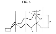
- the conventional suspension has a uniform disk shape in a circumference direction and a closed structure. Therefore, as shown in an arbitrary point P of Fig. 5, which is a sectional view of the suspension in vibration and demonstrated later, when the suspension vibrates by ⁇ X, a radius of point P changes by ⁇ r, so that force is generated in a circumference direction.
- a suspension includes a plurality of roll sections each of which has a semicylindrical shape in a cross section.
- the roll sections are disposed side by side based on a straight line connecting two points on an inner periphery or an outer periphery.
- the roll sections form a closed loop in a manner that a roll section of the roll sections being disposed first adjoins a roll section of the roll sections being disposed last.
- Adjacent roll sections are coupled with each other through a boundary section forming a continuous three dimensional curved surface.
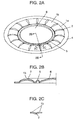
- Fig. 1A is a plan view of a suspension in accordance with the first exemplary embodiment of the present invention.
- Fig. 1B is a sectional view of Fig. 1A taken along the line 1B-1B.
- Fig. 2A is a perspective view of Fig. 1A.
- Fig. 2B is an enlarged sectional view of Fig. 2A taken along the line 2B-2B.
- Fig. 2C is an enlarged sectional view of Fig. 2A taken along the line 2C-2C.
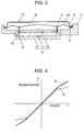
- Fig. 3 is a sectional view of an electro-acoustic transducer using the suspension.
- Fig. 4 is a graph showing a force-displacement characteristic of the suspension in vibration.
- Fig. 5 shows a condition of the suspension in vibration.
- roll sections 1b are disposed radially at a periphery of diaphragm 6 so as to form suspension 1a.
- Connecting part 3 between frame fixing part 4 and vibration system fixing part 5 is formed linear.
- Adjacent roll sections 1b are coupled with each other through boundary section 2 which forms a continuous three dimensional curved surface.
- Non-continuous parts of connecting parts 3 between frame fixing part 4 and vibration system fixing part 5 are trimmed, so that connecting parts 3 forms a closed loop. Because a plane of vibration is structured as a circle, an ellipse, or a polygon such as a quadrilateral or a rectangle in its plan view, roll section 1b is not limited in size or arrangement.
- each roll section 1b has the same shape, roll sections 1b are disposed at regular intervals, thereby forming a closed loop. Adjacent roll sections 1b are coupled with each other through boundary section 2 which forms a continuous three dimensional curved surface. Non-continuous parts of connecting parts 3 between frame fixing part 4 and vibration system fixing part 5 are trimmed, so that connecting parts 3 form a closed loop.
- An outer periphery part of suspension 1a is fixed to frame 11 by frame fixing part 4, and an inner periphery part thereof is fixed to diaphragm 6 or voice coil 10 by vibration system fixing part 5.
- connecting part 3 of roll section 1b is formed linear, force caused by generation of ⁇ r in Fig. 5 is not generated in lateral direction.
- boundary section 2 accommodates stress generated at a boundary between adjacent roll sections 1b. Therefore, as shown in "B" at large amplitude of the force-displacement characteristic of Fig. 4, a superior linearity of compliance can be obtained even at large amplitude, so that unnecessary resonance can be restricted.
- boundary section 2 covers a gap between roll sections 1b, so that dust can be prevented at magnetic gap 9.
- a sectional shape of boundary section 2 between roll sections 1b is not limited to a semicylindrical shape shown in Fig. 2C.
- the outer periphery part of the suspension is fixed to the roll sections forming a closed loop, and non-continuous parts are trimmed, so that the suspension is formed. Connection between the roll sections and the inner periphery part is trimmed, so that generation of distortion or the like is prevented.
- frame fixing part 4 which is a connecting part between an outer linear portion of roll section 1b and frame 11, is trimmed to be formed as a continuous shape and fixed to frame 11.
- vibration system fixing part 5 which is a connecting part between an inner linear portion of roll section 1b and diaphragm 6, is trimmed to be formed as a continuous shape and fixed to diaphragm 6 or voice coil 10.
- an odd number of roll sections 1b are described. Because the roll sections disposed at a periphery are formed asymmetric, generation of rolling in driving is prevented when the suspension is mounted in an electro-acoustic transducer.
- amplitude becomes stable, so that deformation, which causes the rolling phenomenon, of suspension 1a can be prevented. As a result, distortion which affects acoustic characteristics can be reduced.
- suspension 1a may be formed by heat-molding of a polymer resin film or thermoplastic elastomer film, or formed by injection-molding of resin. Using the method mentioned above, a complicated shape is easy to be formed, and suspension 1a can be integrally molded with diaphragm 6, so that the number of manufacturing processes can decrease.
- suspension 1a may be formed by weaving vegetable fiber and/or chemical fiber, impregnating resin and press-molding.
- suspension 1a may be formed by heat-molding a sliced sheet of polyurethane form which is obtained after chemical reaction of mixing of isocyanate and polyol.
- suspension 1a may be formed by vulcanizing unvulcanized compositions such as NBR, SBR or EPDM, which are pliable material, using heat press. Using suspension 1a discussed above, deformation can be prevented and a linearity of compliance can be obtained.
- suspension 1a is coupled with diaphragm 6, however, suspension 1a may be fixed to voice coil 10.
- roll section 1b is formed based on a straight line connecting two points on an outer periphery, however, roll section 1b may be formed based on a straight line connecting two points on an inner periphery
- Fig. 6A is a plan view of suspension device 20 in accordance with the second exemplary embodiment of the present invention.
- Fig. 6B is a sectional view of Fig. 6A taken along the line 6B-6B.
- Suspensions 1c and 1d each have the same shape as suspension 1a, and are fixed to voice coil 10. Suspension 1c is placed above suspension 1d at a certain distance. Suspension device 20 has suspensions 1c and 1d. Suspension 1c may be fixed to or integrally molded with diaphragm 6.
- Fig. 7A is a plan view of suspension device 20 in accordance with the third exemplary embodiment of the present invention.
- Fig. 7B is a sectional view of Fig. 7A taken along the line 7B-7B.
- Suspension device 20 has suspensions 1c and 1d.
- Suspensions 1c and 1d each have the same shape as suspension 1a, and suspension 1c is shifted from suspension 1d by approximately 1/2 of width "L" of the roll section in a rotating direction (i.e., a periphery direction).
- suspensions 1c and 1d are disposed in a substantially vertical direction, and one of suspensions 1c and 1d is rotated by 1/2 of a width of the roll section with respect to an axis in the periphery direction. Generation of rolling in driving can be prevented when the suspension is mounted in an electro-acoustic transducer.
- Suspensions 1c and 1d are fixed to voice coil 10 and spaced each other. Suspension 1c may have the same direction as suspension 1d or have a reverse direction of suspension 1d. Using the structure discussed above, rigidity of suspension device 20 increases and rolling is further prevented.
- upper suspension 1c is fixed to the diaphragm, however, suspension 1c may be coupled with voice coil 10.
- the present invention provides a suspension where stress generated at its inside in a circumference direction is individually divided. Using this structure, a superior linearity of compliance can be obtained, distortion which affects acoustic characteristics can be reduced and rolling caused by deformation can be restricted. As a result, the suspension which is suitable for large amplitude and has supporting functions can be obtained. Therefore, an electro-acoustic transducer which can expand low-tone-reproducing bands by reducing a minimum resonance frequency is provided, even when it is structured with the same width as a conventional one.
Landscapes
- Engineering & Computer Science (AREA)
- Physics & Mathematics (AREA)
- Acoustics & Sound (AREA)
- Signal Processing (AREA)
- Multimedia (AREA)
- Audible-Bandwidth Dynamoelectric Transducers Other Than Pickups (AREA)
- Diaphragms For Electromechanical Transducers (AREA)
- Investigating Or Analyzing Materials By The Use Of Ultrasonic Waves (AREA)
Abstract
Description
- The present invention relates to a suspension used in an apparatus for reproducing a sound such as a voice, music or a dial tone, and an electro-acoustic transducer using the same.
- A conventional electro- acoustic transducer is demonstrated hereinafter with reference to Figs. 8, 9A and 9B. Fig. 8 is a sectional view of the electro-acoustic transducer. Fig. 9A is a plan view of a diaphragm. Fig. 9B is a sectional view of Fig. 9A taken along the
line 9B-9B. In Fig 8,diaphragm 6 generates aerial vibration.Diaphragm 6 is fixed toframe 11 byframe fixing part 4 throughsuspension 1 which has vibrating functions and supporting functions.Suspension 1 is of a semicylindrical shape in a cross section and uniform in a circumference direction.Diaphragm 6 is coupled withvoice coil 10.Voice coil 10 is placed withinmagnetic gap 9 ofmagnetic circuit 8 which is provided at the middle of theframe 11 and formed ofplate 13,magnet 14 andyoke 15. - Furthermore,
protector 12 for protectingdiaphragm 6 is bonded by using an adhesive. An operation of an electromotive loudspeaker structured mentioned above is described hereinafter. - When a current flows in
voice coil 10, the current crosses a magnetic field inmagnetic gap 9 at right angles, and driving force generated atvoice coil 10 is transmitted todiaphragm 6. Thensuspension 1 supportsvoice coil 10 in a manner thatvoice coil 10 becomes concentric withplate 13, and works as a spring in a vibrating direction whendiaphragm 6 vibrates. When an alternating current (e.g., a voice signal) flows invoice coil 10,voice coil 10 anddiaphragm 6 vibrate while being supported bysuspension 1. As a result, air vibrates and a compressional wave is generated, so that a sound can be heard. For example, Japanese Patent Unexamined Publication H5-103395 is known as a related art of this invention. - However, the conventional suspension has a uniform disk shape in a circumference direction and a closed structure. Therefore, as shown in an arbitrary point P of Fig. 5, which is a sectional view of the suspension in vibration and demonstrated later, when the suspension vibrates by ΔX, a radius of point P changes by Δr, so that force is generated in a circumference direction.
- This force is easy to be generated according as the suspension vibrates at large amplitude. As shown in line "A" of Fig. 4, which is a force-displacement characteristic and demonstrated later, compliance becomes non-linear at the large amplitude. Non-linearity of the compliance of supporting force, which is caused by a shape of
suspension 1, causes distortion particularly in reproduction of a low tone area where amplitude becomes large. - Compliance of the suspension becomes difficult to be maintained due to these phenomena, so that harmonic distortion is generated at sound pressure frequency characteristics. In addition, a deformation of the suspension is also induced, thereby causing a rolling phenomenon of the diaphragm.
- A suspension includes a plurality of roll sections each of which has a semicylindrical shape in a cross section. The roll sections are disposed side by side based on a straight line connecting two points on an inner periphery or an outer periphery. The roll sections form a closed loop in a manner that a roll section of the roll sections being disposed first adjoins a roll section of the roll sections being disposed last. Adjacent roll sections are coupled with each other through a boundary section forming a continuous three dimensional curved surface.
-
- Fig. 1A is a plan view of a suspension in accordance with a first exemplary embodiment of the present invention.
- Fig. 1B is a sectional view of the suspension of Fig. 1A taken along the
line 1B-1B in accordance with the first exemplary embodiment of the present invention. - Fig. 2A is a perspective view of the suspension in accordance with the first exemplary embodiment of the present invention.
- Fig. 2B is an enlarged sectional view of the suspension of Fig. 2A taken
along the
line 2B-2B in accordance with the first exemplary embodiment of the present invention. - Fig. 2C is an enlarged sectional view of the suspension of Fig. 2A taken
along the
line 2C-2C in accordance with the first exemplary embodiment of the present invention. - Fig. 3 is a sectional view of an electro-acoustic transducer using the suspension in accordance with the first exemplary embodiment of the present invention.
- Fig. 4 is a graph showing a force -displacement characteristic of the suspension in vibration in accordance with the first exemplary embodiment of the present invention.
- Fig. 5 shows a condition of the suspension in vibration in accordance with the first exemplary embodiment of the present invention.
- Fig. 6A is a plan view of a suspension device in accordance with a second exemplary embodiment of the present invention.
- Fig. 6B is a sectional view of the suspension device of Fig. 6A taken along the line 6B-6B in accordance with the second exemplary embodiment of the present invention.
- Fig. 7A is a plan view of a suspension device in accordance with a third exemplary embodiment of the present invention.
- Fig. 7B is a sectional view of the suspension device of Fig. 7A taken along
the
line 7B-7B in accordance with the third exemplary embodiment of the present invention. - Fig. 8 is a sectional view of a conventional electro-acoustic transducer.
- Fig. 9A is a plan view of a suspension which is an essential part of the conventional electro-acoustic transducer.
- Fig. 9B is a sectional view of the suspension of the conventional
electro-acoustic transducer of Fig. 9A taken along the
line 9B-9B. -
- Exemplary embodiments of suspensions of the present invention are demonstrated hereinafter with reference to Fig 1 through Fig 7B. In the description, the same elements used in the background art have the same reference marks, and the descriptions of those elements are omitted here.
- The first exemplary embodiment of the present invention is demonstrated hereinafter with reference to Fig 1 through Fig 5.
- Fig. 1A is a plan view of a suspension in accordance with the first exemplary embodiment of the present invention. Fig. 1B is a sectional view of Fig. 1A taken along the
line 1B-1B. Fig. 2A is a perspective view of Fig. 1A. Fig. 2B is an enlarged sectional view of Fig. 2A taken along theline 2B-2B. Fig. 2C is an enlarged sectional view of Fig. 2A taken along theline 2C-2C. Fig. 3 is a sectional view of an electro-acoustic transducer using the suspension. Fig. 4 is a graph showing a force-displacement characteristic of the suspension in vibration. Fig. 5 shows a condition of the suspension in vibration. - In Figs. 1A and 1B,
roll sections 1b are disposed radially at a periphery ofdiaphragm 6 so as to formsuspension 1a.Connecting part 3 betweenframe fixing part 4 and vibrationsystem fixing part 5 is formed linear.Adjacent roll sections 1b are coupled with each other throughboundary section 2 which forms a continuous three dimensional curved surface. Non-continuous parts of connectingparts 3 betweenframe fixing part 4 and vibrationsystem fixing part 5 are trimmed, so that connectingparts 3 forms a closed loop. Because a plane of vibration is structured as a circle, an ellipse, or a polygon such as a quadrilateral or a rectangle in its plan view,roll section 1b is not limited in size or arrangement. - When each
roll section 1b has the same shape,roll sections 1b are disposed at regular intervals, thereby forming a closed loop.Adjacent roll sections 1b are coupled with each other throughboundary section 2 which forms a continuous three dimensional curved surface. Non-continuous parts of connectingparts 3 betweenframe fixing part 4 and vibrationsystem fixing part 5 are trimmed, so that connectingparts 3 form a closed loop. An outer periphery part ofsuspension 1a is fixed to frame 11 byframe fixing part 4, and an inner periphery part thereof is fixed todiaphragm 6 orvoice coil 10 by vibrationsystem fixing part 5. - Because connecting
part 3 ofroll section 1b is formed linear, force caused by generation of Δr in Fig. 5 is not generated in lateral direction. Because of deformation of a semicylindrical shape ofroll section 1b in vibration,boundary section 2 accommodates stress generated at a boundary betweenadjacent roll sections 1b. Therefore, as shown in "B" at large amplitude of the force-displacement characteristic of Fig. 4, a superior linearity of compliance can be obtained even at large amplitude, so that unnecessary resonance can be restricted. In addition,boundary section 2 covers a gap betweenroll sections 1b, so that dust can be prevented atmagnetic gap 9. - Besides, a sectional shape of
boundary section 2 betweenroll sections 1b is not limited to a semicylindrical shape shown in Fig. 2C. - The outer periphery part of the suspension is fixed to the roll sections forming a closed loop, and non-continuous parts are trimmed, so that the suspension is formed. Connection between the roll sections and the inner periphery part is trimmed, so that generation of distortion or the like is prevented.
- In addition,
frame fixing part 4, which is a connecting part between an outer linear portion ofroll section 1b andframe 11, is trimmed to be formed as a continuous shape and fixed to frame 11. - Furthermore, vibration
system fixing part 5, which is a connecting part between an inner linear portion ofroll section 1b anddiaphragm 6, is trimmed to be formed as a continuous shape and fixed todiaphragm 6 orvoice coil 10. - According to the first exemplary embodiment, an odd number of
roll sections 1b are described. Because the roll sections disposed at a periphery are formed asymmetric, generation of rolling in driving is prevented when the suspension is mounted in an electro-acoustic transducer. - Using the structure discussed above, amplitude becomes stable, so that deformation, which causes the rolling phenomenon, of
suspension 1a can be prevented. As a result, distortion which affects acoustic characteristics can be reduced. - In addition,
suspension 1a may be formed by heat-molding of a polymer resin film or thermoplastic elastomer film, or formed by injection-molding of resin. Using the method mentioned above, a complicated shape is easy to be formed, andsuspension 1a can be integrally molded withdiaphragm 6, so that the number of manufacturing processes can decrease. - Furthermore,
suspension 1a may be formed by weaving vegetable fiber and/or chemical fiber, impregnating resin and press-molding. In addition,suspension 1a may be formed by heat-molding a sliced sheet of polyurethane form which is obtained after chemical reaction of mixing of isocyanate and polyol. Besides,suspension 1a may be formed by vulcanizing unvulcanized compositions such as NBR, SBR or EPDM, which are pliable material, using heat press. Usingsuspension 1a discussed above, deformation can be prevented and a linearity of compliance can be obtained. - According to the first embodiment,
suspension 1a is coupled withdiaphragm 6, however,suspension 1a may be fixed tovoice coil 10. - Furthermore, according to the first embodiment,
roll section 1b is formed based on a straight line connecting two points on an outer periphery, however, rollsection 1b may be formed based on a straight line connecting two points on an inner periphery - The second exemplary embodiment of
suspension device 20 of the present invention is demonstrated hereinafter with reference to Figs 6A and 6B. - Fig. 6A is a plan view of
suspension device 20 in accordance with the second exemplary embodiment of the present invention. Fig. 6B is a sectional view of Fig. 6A taken along the line 6B-6B. - Only different point between the first embodiment and the second embodiment is described hereinafter with reference to Figs. 6A and 6B.
Suspensions suspension 1a, and are fixed tovoice coil 10.Suspension 1c is placed abovesuspension 1d at a certain distance.Suspension device 20 hassuspensions Suspension 1c may be fixed to or integrally molded withdiaphragm 6. - The third exemplary embodiment of
suspension device 20 of the present invention is demonstrated hereinafter with reference to Figs 7A and 7B. - Fig. 7A is a plan view of
suspension device 20 in accordance with the third exemplary embodiment of the present invention. Fig. 7B is a sectional view of Fig. 7A taken along theline 7B-7B.Suspension device 20 hassuspensions Suspensions suspension 1a, andsuspension 1c is shifted fromsuspension 1d by approximately 1/2 of width "L" of the roll section in a rotating direction (i.e., a periphery direction). - In other words,
suspensions suspensions -
Suspensions voice coil 10 and spaced each other.Suspension 1c may have the same direction assuspension 1d or have a reverse direction ofsuspension 1d. Using the structure discussed above, rigidity ofsuspension device 20 increases and rolling is further prevented. - According to the second and third embodiments,
upper suspension 1c is fixed to the diaphragm, however,suspension 1c may be coupled withvoice coil 10. - In addition, rolling is further prevented by widening interval "d" between
suspensions - The present invention provides a suspension where stress generated at its inside in a circumference direction is individually divided. Using this structure, a superior linearity of compliance can be obtained, distortion which affects acoustic characteristics can be reduced and rolling caused by deformation can be restricted. As a result, the suspension which is suitable for large amplitude and has supporting functions can be obtained. Therefore, an electro-acoustic transducer which can expand low-tone-reproducing bands by reducing a minimum resonance frequency is provided, even when it is structured with the same width as a conventional one.
Claims (8)
- A suspension comprising:a plurality of roll sections each of which has a semicylindrical shape in a cross section,wherein the roll sections are disposed side by side based on a straight line connecting two points on an inner periphery or an outer periphery,wherein the roll sections form a closed loop in a manner that a roll section of the roll sections being disposed first adjoins a roll section of the roll sections being disposed last,wherein adjacent roll sections are coupled with each other through a boundary section forming a continuous three dimensional curved surface.
- A suspension comprising:a plurality of roll sections each of which has a semicylindrical shape in a cross section,wherein the roll sections are disposed radially side by side at regular intervals based on a straight line connecting two points on an inner periphery or an outer periphery,wherein the roll sections form a closed loop in a manner that a roll section of the roll sections being disposed first adjoins a roll section of the roll sections being disposed last,wherein adjacent roll sections are coupled with each other through a boundary section forming a continuous three dimensional curved surface.
- The suspension of claim 1 or 2,wherein the inner periphery is coupled with the roll sections forming the closed loop, and non-continuous parts of the inner periphery are trimmed,wherein the outer periphery has a frame fixing part for being fixed at a frame.
- The suspension of claim 1 or 2,wherein the outer periphery is coupled with the roll sections forming the closed loop, and non-continuous parts of the outer periphery are trimmed,wherein the inner periphery has a vibration system fixing part for fixing a diaphragm or a voice coil.
- The suspension of claim 1 or 2,wherein an odd number of the roll sections are disposed.
- A suspension device comprising:two suspensions of claim 1 or 2 being disposed in a substantially vertical direction.
- A suspension device comprising:two suspensions of claim 1 or 2 being disposed in a substantially vertical direction,wherein one of the suspensions is rotated by 1/2 of a width of the roll section with respect to an axis in a periphery direction.
- An electro-acoustic transducer comprising:a suspension of claim 1 or 2,wherein the inner periphery is coupled with a voice coil placed in a magnetic gap of a magnetic circuit or an outer periphery part of a diaphragm coupled with the voice coil,wherein the outer periphery is fixed to a frame which supports the magnetic circuit and a vibration system.
Applications Claiming Priority (3)
| Application Number | Priority Date | Filing Date | Title |
|---|---|---|---|
| JP2002310771A JP3896945B2 (en) | 2002-04-03 | 2002-10-25 | Suspension and electroacoustic transducer using the same |
| JP2002310771 | 2002-10-25 | ||
| PCT/JP2003/012644 WO2004039124A1 (en) | 2002-10-25 | 2003-10-02 | Suspension and electro-acoustic transducer using the suspension |
Publications (2)
| Publication Number | Publication Date |
|---|---|
| EP1553801A1 true EP1553801A1 (en) | 2005-07-13 |
| EP1553801A4 EP1553801A4 (en) | 2008-01-09 |
Family
ID=32171060
Family Applications (1)
| Application Number | Title | Priority Date | Filing Date |
|---|---|---|---|
| EP03753988A Withdrawn EP1553801A4 (en) | 2002-10-25 | 2003-10-02 | Suspension and electro-acoustic transducer using the suspension |
Country Status (7)
| Country | Link |
|---|---|
| US (1) | US7428946B2 (en) |
| EP (1) | EP1553801A4 (en) |
| KR (1) | KR100676719B1 (en) |
| CN (1) | CN1692676B (en) |
| AU (1) | AU2003272919A1 (en) |
| RU (1) | RU2290771C2 (en) |
| WO (1) | WO2004039124A1 (en) |
Families Citing this family (30)
| Publication number | Priority date | Publication date | Assignee | Title |
|---|---|---|---|---|
| US6851513B2 (en) * | 2001-03-27 | 2005-02-08 | Harvard International Industries, Incorporated | Tangential stress reduction system in a loudspeaker suspension |
| EP1694094A1 (en) * | 2005-02-18 | 2006-08-23 | AKG Acoustics GmbH | Membrane for a dynamic converter |
| DE102006058369B4 (en) * | 2006-12-08 | 2014-01-23 | Sennheiser Electronic Gmbh & Co. Kg | Electroacoustic transducer |
| US7931115B2 (en) * | 2007-05-31 | 2011-04-26 | Bose Corporation | Diaphragm surrounding |
| US7699139B2 (en) * | 2007-05-31 | 2010-04-20 | Bose Corporation | Diaphragm surround |
| WO2009107192A1 (en) * | 2008-02-25 | 2009-09-03 | パイオニア株式会社 | Vibrator for acoustic converter, and speaker device |
| TWI419578B (en) * | 2008-12-26 | 2013-12-11 | Merry Electronics Co Ltd | Diaphragm of electro-acoustic transducer |
| US20100236861A1 (en) * | 2009-03-17 | 2010-09-23 | Merry Electronics Co., Ltd. | Diaphragm of electro-acoustic transducer |
| US20110293120A1 (en) * | 2010-05-25 | 2011-12-01 | Timothy Val Kolton | Earphone transducer |
| CN202004956U (en) * | 2010-12-31 | 2011-10-05 | 瑞声光电科技(常州)有限公司 | Acoustic generator |
| US9351078B2 (en) * | 2011-05-19 | 2016-05-24 | Tang Band Industries Co., Ltd. | Vibrating panel device for electromagnetic vibrator and its manufacture method |
| US8397861B1 (en) | 2012-03-02 | 2013-03-19 | Bose Corporation | Diaphragm surround |
| CN202949560U (en) * | 2012-11-16 | 2013-05-22 | 瑞声声学科技(常州)有限公司 | Sounder |
| US9788122B2 (en) * | 2012-12-26 | 2017-10-10 | Xin Min HUANG | Vibrating panel device for electromagnetic vibrator and manufacture method thereof |
| KR101483089B1 (en) * | 2013-04-24 | 2015-01-19 | 주식회사 이엠텍 | Suspension for sound transducer |
| US9253576B2 (en) | 2013-11-21 | 2016-02-02 | Bose Corporation | Suspension for acoustic device |
| US10129650B2 (en) * | 2013-12-19 | 2018-11-13 | Tang Band Industries Co., Ltd. | Vibration unit for acoustic arrangement |
| CN204031456U (en) * | 2014-01-22 | 2014-12-17 | 宁波升亚电子有限公司 | A kind of non-elastic wave loudspeaker |
| US10129652B2 (en) * | 2014-09-12 | 2018-11-13 | Apple Inc. | Audio speaker surround geometry for improved pistonic motion |
| US9466280B2 (en) | 2014-10-24 | 2016-10-11 | Bose Corporation | Acoustic device suspension |
| US9654879B2 (en) | 2014-10-24 | 2017-05-16 | Bose Corporation | Suspension for acoustic device |
| CN105872916B (en) * | 2015-01-22 | 2023-04-21 | 宁波升亚电子有限公司 | Spring rib type hanging edge, loudspeaker and manufacturing method thereof |
| US9924273B2 (en) | 2016-03-31 | 2018-03-20 | Bose Corporation | Acoustic device configuration and method |
| CN205961442U (en) * | 2016-07-21 | 2017-02-15 | 瑞声科技(新加坡)有限公司 | Loudspeaker |
| CN205847592U (en) * | 2016-07-21 | 2016-12-28 | 瑞声科技(新加坡)有限公司 | Speaker |
| GB2560496B (en) * | 2017-03-16 | 2021-09-29 | Gp Acoustics Uk Ltd | Loudspeaker driver surround |
| USD916053S1 (en) * | 2018-11-09 | 2021-04-13 | Purifi Aps | Part of a loudspeaker |
| CN109936804A (en) * | 2019-02-28 | 2019-06-25 | 瑞声光电科技(常州)有限公司 | Sound film and microphone device with the sound film |
| USD966235S1 (en) | 2019-08-23 | 2022-10-11 | Tymphany Acoustic Technology Limited | Waveguide |
| USD971176S1 (en) * | 2019-09-18 | 2022-11-29 | Sony Corporation | Acoustic transducer |
Citations (4)
| Publication number | Priority date | Publication date | Assignee | Title |
|---|---|---|---|---|
| GB393313A (en) * | 1931-12-02 | 1933-06-02 | Alexander Isidore Abrahams | Improvements in or connected with diaphragms or the like for sound reproducers |
| GB2348336A (en) * | 1999-03-24 | 2000-09-27 | Edwin William Form | A suspension for diaphragm actuators |
| JP2001128284A (en) * | 1999-11-01 | 2001-05-11 | Foster Electric Co Ltd | Electroacoustic transducer |
| WO2003009640A2 (en) * | 2001-07-19 | 2003-01-30 | Koninklijke Philips Electronics N.V. | Electroacoustic transducer comprising a membrane with an improved pleats area |
Family Cites Families (16)
| Publication number | Priority date | Publication date | Assignee | Title |
|---|---|---|---|---|
| US4324312A (en) * | 1978-11-14 | 1982-04-13 | James B. Lansing Sound, Inc. | Diaphragm suspension construction |
| JPS5734789U (en) * | 1980-07-31 | 1982-02-24 | ||
| JPS5734789A (en) | 1980-08-12 | 1982-02-25 | Toshiba Corp | Controlling device for synchronous motor |
| US4881617A (en) * | 1988-12-30 | 1989-11-21 | Alexander Faraone | Radially arcuated speaker cone |
| JP2949957B2 (en) * | 1991-10-07 | 1999-09-20 | 松下電器産業株式会社 | Speaker damper |
| DE69535049T2 (en) * | 1994-04-25 | 2007-05-10 | Matsushita Electric Industrial Co., Ltd., Kadoma | Extended speaker |
| TW353849B (en) * | 1996-11-29 | 1999-03-01 | Matsushita Electric Ind Co Ltd | Electric-to-mechanical-to-acoustic converter and portable terminal unit |
| US5880412A (en) * | 1997-11-10 | 1999-03-09 | Faraone; Alexander | High frequency radially arcuated center speaker cone |
| DE19757098C2 (en) * | 1997-12-20 | 2003-01-09 | Harman Audio Electronic Sys | Suspension for sound reproduction arrangements based on the bending wave principle |
| JP3796937B2 (en) * | 1998-01-13 | 2006-07-12 | 松下電器産業株式会社 | Speaker |
| US20030068064A1 (en) * | 2001-10-09 | 2003-04-10 | Czerwinski Eugene J. | Neoprene surround for an electro-dynamic acoustical transducer |
| US20030228027A1 (en) * | 1998-01-28 | 2003-12-11 | Czerwinski Eugene J. | Sub-woofer with two passive radiators |
| US6044925A (en) * | 1998-11-30 | 2000-04-04 | Sahyoun; Joseph Yaacoub | Passive speaker |
| JP2002095086A (en) | 2000-09-18 | 2002-03-29 | Onkyo Corp | Loudspeaker unit |
| US6851513B2 (en) * | 2001-03-27 | 2005-02-08 | Harvard International Industries, Incorporated | Tangential stress reduction system in a loudspeaker suspension |
| US7054459B2 (en) * | 2002-05-17 | 2006-05-30 | Matsushita Electric Industrial Co., Ltd. | Surrounding structure of a loudspeaker |
-
2003
- 2003-10-02 CN CN2003801007239A patent/CN1692676B/en not_active Expired - Lifetime
- 2003-10-02 AU AU2003272919A patent/AU2003272919A1/en not_active Abandoned
- 2003-10-02 KR KR1020057004342A patent/KR100676719B1/en not_active IP Right Cessation
- 2003-10-02 US US10/523,694 patent/US7428946B2/en not_active Expired - Lifetime
- 2003-10-02 WO PCT/JP2003/012644 patent/WO2004039124A1/en active Application Filing
- 2003-10-02 RU RU2005108356/28A patent/RU2290771C2/en not_active IP Right Cessation
- 2003-10-02 EP EP03753988A patent/EP1553801A4/en not_active Withdrawn
Patent Citations (5)
| Publication number | Priority date | Publication date | Assignee | Title |
|---|---|---|---|---|
| GB393313A (en) * | 1931-12-02 | 1933-06-02 | Alexander Isidore Abrahams | Improvements in or connected with diaphragms or the like for sound reproducers |
| GB2348336A (en) * | 1999-03-24 | 2000-09-27 | Edwin William Form | A suspension for diaphragm actuators |
| JP2001128284A (en) * | 1999-11-01 | 2001-05-11 | Foster Electric Co Ltd | Electroacoustic transducer |
| US6516077B1 (en) * | 1999-11-01 | 2003-02-04 | Foster Electric Company | Electroacoustic transducer |
| WO2003009640A2 (en) * | 2001-07-19 | 2003-01-30 | Koninklijke Philips Electronics N.V. | Electroacoustic transducer comprising a membrane with an improved pleats area |
Non-Patent Citations (1)
| Title |
|---|
| See also references of WO2004039124A1 * |
Also Published As
| Publication number | Publication date |
|---|---|
| WO2004039124A1 (en) | 2004-05-06 |
| KR20050043956A (en) | 2005-05-11 |
| EP1553801A4 (en) | 2008-01-09 |
| RU2290771C2 (en) | 2006-12-27 |
| AU2003272919A1 (en) | 2004-05-13 |
| CN1692676A (en) | 2005-11-02 |
| KR100676719B1 (en) | 2007-02-01 |
| US20060162993A1 (en) | 2006-07-27 |
| CN1692676B (en) | 2011-01-12 |
| US7428946B2 (en) | 2008-09-30 |
| RU2005108356A (en) | 2005-08-10 |
Similar Documents
| Publication | Publication Date | Title |
|---|---|---|
| US7428946B2 (en) | Suspension and electro-acoustic transducer using the suspension | |
| US8199962B2 (en) | Loudspeaker diaphragm and loudspeaker using the same | |
| EP1786237B1 (en) | Speaker | |
| JP2007142982A (en) | Speaker apparatus | |
| US20080063234A1 (en) | Electroacoustic transducer | |
| EP1091616A1 (en) | Loudspeaker diaphragm | |
| US20170085979A1 (en) | Electroacoustic Transducer | |
| CN112911470A (en) | Loudspeaker module | |
| WO2011007403A1 (en) | Electromagnetic converter | |
| US20030068064A1 (en) | Neoprene surround for an electro-dynamic acoustical transducer | |
| JP2009201005A (en) | Motor-driven type speaker | |
| JP4578986B2 (en) | Dynamic microphone unit and manufacturing method thereof | |
| KR20060058711A (en) | Shallow loudspeaker | |
| WO2011024398A1 (en) | Electroacoustic transducer | |
| JP4513220B2 (en) | Speaker device | |
| JP4301531B2 (en) | Multi-functional pronunciation body | |
| JP6065819B2 (en) | Electroacoustic transducer | |
| JP2000004569A (en) | Oscillating actuator | |
| JP4134419B2 (en) | Speaker | |
| WO2013099790A1 (en) | Headphones and headphone driver | |
| JP2000316268A (en) | Vibration actuator | |
| JP3896945B2 (en) | Suspension and electroacoustic transducer using the same | |
| JP2002281587A (en) | Speaker | |
| JP6187666B2 (en) | Electroacoustic transducer | |
| JP4413119B2 (en) | Speaker |
Legal Events
| Date | Code | Title | Description |
|---|---|---|---|
| PUAI | Public reference made under article 153(3) epc to a published international application that has entered the european phase |
Free format text: ORIGINAL CODE: 0009012 |
|
| 17P | Request for examination filed |
Effective date: 20050311 |
|
| AK | Designated contracting states |
Kind code of ref document: A1 Designated state(s): AT BE BG CH CY CZ DE DK EE ES FI FR GB GR HU IE IT LI LU MC NL PT RO SE SI SK TR |
|
| AX | Request for extension of the european patent |
Extension state: AL LT LV MK |
|
| DAX | Request for extension of the european patent (deleted) | ||
| RIN1 | Information on inventor provided before grant (corrected) |
Inventor name: OMORI, TATSUYA Inventor name: SANO, KOJI Inventor name: HONDA, KAZUKI |
|
| A4 | Supplementary search report drawn up and despatched |
Effective date: 20071206 |
|
| RAP1 | Party data changed (applicant data changed or rights of an application transferred) |
Owner name: PANASONIC CORPORATION |
|
| 17Q | First examination report despatched |
Effective date: 20100818 |
|
| STAA | Information on the status of an ep patent application or granted ep patent |
Free format text: STATUS: THE APPLICATION IS DEEMED TO BE WITHDRAWN |
|
| 18D | Application deemed to be withdrawn |
Effective date: 20101229 |