EP1550628A1 - Method and apparatus for processing sheets of different sizes to a mail item - Google Patents
Method and apparatus for processing sheets of different sizes to a mail item Download PDFInfo
- Publication number
- EP1550628A1 EP1550628A1 EP04078571A EP04078571A EP1550628A1 EP 1550628 A1 EP1550628 A1 EP 1550628A1 EP 04078571 A EP04078571 A EP 04078571A EP 04078571 A EP04078571 A EP 04078571A EP 1550628 A1 EP1550628 A1 EP 1550628A1
- Authority
- EP
- European Patent Office
- Prior art keywords
- sheet
- sheets
- conveyor track
- size
- folding
- Prior art date
- Legal status (The legal status is an assumption and is not a legal conclusion. Google has not performed a legal analysis and makes no representation as to the accuracy of the status listed.)
- Granted
Links
- 238000000034 method Methods 0.000 title claims description 10
- 230000004044 response Effects 0.000 claims abstract description 14
- 238000001514 detection method Methods 0.000 claims description 6
- 230000008878 coupling Effects 0.000 description 13
- 238000010168 coupling process Methods 0.000 description 13
- 238000005859 coupling reaction Methods 0.000 description 13
- 238000011144 upstream manufacturing Methods 0.000 description 4
- 239000000853 adhesive Substances 0.000 description 3
- 230000001070 adhesive effect Effects 0.000 description 3
- 239000000969 carrier Substances 0.000 description 2
- 230000001419 dependent effect Effects 0.000 description 1
- 230000000694 effects Effects 0.000 description 1
- 238000012544 monitoring process Methods 0.000 description 1
- 238000003672 processing method Methods 0.000 description 1
- 238000000926 separation method Methods 0.000 description 1
- 230000011664 signaling Effects 0.000 description 1
Images
Classifications
-
- B—PERFORMING OPERATIONS; TRANSPORTING
- B43—WRITING OR DRAWING IMPLEMENTS; BUREAU ACCESSORIES
- B43M—BUREAU ACCESSORIES NOT OTHERWISE PROVIDED FOR
- B43M3/00—Devices for inserting documents into envelopes
- B43M3/04—Devices for inserting documents into envelopes automatic
-
- B—PERFORMING OPERATIONS; TRANSPORTING
- B65—CONVEYING; PACKING; STORING; HANDLING THIN OR FILAMENTARY MATERIAL
- B65H—HANDLING THIN OR FILAMENTARY MATERIAL, e.g. SHEETS, WEBS, CABLES
- B65H39/00—Associating, collating, or gathering articles or webs
- B65H39/02—Associating,collating or gathering articles from several sources
- B65H39/04—Associating,collating or gathering articles from several sources from piles
- B65H39/043—Associating,collating or gathering articles from several sources from piles the piles being disposed in juxtaposed carriers
-
- B—PERFORMING OPERATIONS; TRANSPORTING
- B65—CONVEYING; PACKING; STORING; HANDLING THIN OR FILAMENTARY MATERIAL
- B65H—HANDLING THIN OR FILAMENTARY MATERIAL, e.g. SHEETS, WEBS, CABLES
- B65H39/00—Associating, collating, or gathering articles or webs
- B65H39/02—Associating,collating or gathering articles from several sources
- B65H39/04—Associating,collating or gathering articles from several sources from piles
- B65H39/055—Associating,collating or gathering articles from several sources from piles by collecting in juxtaposed carriers
-
- B—PERFORMING OPERATIONS; TRANSPORTING
- B65—CONVEYING; PACKING; STORING; HANDLING THIN OR FILAMENTARY MATERIAL
- B65H—HANDLING THIN OR FILAMENTARY MATERIAL, e.g. SHEETS, WEBS, CABLES
- B65H39/00—Associating, collating, or gathering articles or webs
- B65H39/02—Associating,collating or gathering articles from several sources
- B65H39/06—Associating,collating or gathering articles from several sources from delivery streams
-
- B—PERFORMING OPERATIONS; TRANSPORTING
- B65—CONVEYING; PACKING; STORING; HANDLING THIN OR FILAMENTARY MATERIAL
- B65H—HANDLING THIN OR FILAMENTARY MATERIAL, e.g. SHEETS, WEBS, CABLES
- B65H45/00—Folding thin material
- B65H45/12—Folding articles or webs with application of pressure to define or form crease lines
- B65H45/14—Buckling folders
- B65H45/142—Pocket-type folders
-
- B—PERFORMING OPERATIONS; TRANSPORTING
- B65—CONVEYING; PACKING; STORING; HANDLING THIN OR FILAMENTARY MATERIAL
- B65H—HANDLING THIN OR FILAMENTARY MATERIAL, e.g. SHEETS, WEBS, CABLES
- B65H2301/00—Handling processes for sheets or webs
- B65H2301/40—Type of handling process
- B65H2301/42—Piling, depiling, handling piles
- B65H2301/422—Handling piles, sets or stacks of articles
- B65H2301/4227—Deforming piles, e.g. folding
-
- B—PERFORMING OPERATIONS; TRANSPORTING
- B65—CONVEYING; PACKING; STORING; HANDLING THIN OR FILAMENTARY MATERIAL
- B65H—HANDLING THIN OR FILAMENTARY MATERIAL, e.g. SHEETS, WEBS, CABLES
- B65H2301/00—Handling processes for sheets or webs
- B65H2301/40—Type of handling process
- B65H2301/43—Gathering; Associating; Assembling
- B65H2301/435—Gathering; Associating; Assembling on collecting conveyor
-
- B—PERFORMING OPERATIONS; TRANSPORTING
- B65—CONVEYING; PACKING; STORING; HANDLING THIN OR FILAMENTARY MATERIAL
- B65H—HANDLING THIN OR FILAMENTARY MATERIAL, e.g. SHEETS, WEBS, CABLES
- B65H2301/00—Handling processes for sheets or webs
- B65H2301/40—Type of handling process
- B65H2301/44—Moving, forwarding, guiding material
- B65H2301/445—Moving, forwarding, guiding material stream of articles separated from each other
- B65H2301/4454—Merging two or more streams
-
- B—PERFORMING OPERATIONS; TRANSPORTING
- B65—CONVEYING; PACKING; STORING; HANDLING THIN OR FILAMENTARY MATERIAL
- B65H—HANDLING THIN OR FILAMENTARY MATERIAL, e.g. SHEETS, WEBS, CABLES
- B65H2511/00—Dimensions; Position; Numbers; Identification; Occurrences
- B65H2511/10—Size; Dimensions
- B65H2511/11—Length
-
- B—PERFORMING OPERATIONS; TRANSPORTING
- B65—CONVEYING; PACKING; STORING; HANDLING THIN OR FILAMENTARY MATERIAL
- B65H—HANDLING THIN OR FILAMENTARY MATERIAL, e.g. SHEETS, WEBS, CABLES
- B65H2511/00—Dimensions; Position; Numbers; Identification; Occurrences
- B65H2511/20—Location in space
- B65H2511/22—Distance
-
- B—PERFORMING OPERATIONS; TRANSPORTING
- B65—CONVEYING; PACKING; STORING; HANDLING THIN OR FILAMENTARY MATERIAL
- B65H—HANDLING THIN OR FILAMENTARY MATERIAL, e.g. SHEETS, WEBS, CABLES
- B65H2701/00—Handled material; Storage means
- B65H2701/10—Handled articles or webs
- B65H2701/13—Parts concerned of the handled material
- B65H2701/131—Edges
- B65H2701/1311—Edges leading edge
-
- B—PERFORMING OPERATIONS; TRANSPORTING
- B65—CONVEYING; PACKING; STORING; HANDLING THIN OR FILAMENTARY MATERIAL
- B65H—HANDLING THIN OR FILAMENTARY MATERIAL, e.g. SHEETS, WEBS, CABLES
- B65H2701/00—Handled material; Storage means
- B65H2701/10—Handled articles or webs
- B65H2701/13—Parts concerned of the handled material
- B65H2701/131—Edges
- B65H2701/1313—Edges trailing edge
Definitions
- the invention relates to a method and an apparatus for processing sheets of different sizes to a mail item.
- the sheets may also comprise, for instance, address carriers, brochures, reply cards, prepaid envelopes, carriers with a plastic card, etc.
- this object is achieved by providing a method according to claim 1.
- the invention further provides an apparatus according to claim 4, with which the method according to the invention can be carried out.
- a small sheet which is smaller in conveying direction than a large sheet of that set can be positioned, with respect to the large sheet, with both its leading edge spaced from the leading edge of the large sheet and its trailing edge spaced from the trailing edge of the large sheet, and the sheets can be held in that relative position until folding, small sheets of a large variety of sizes in conveying direction can be folded together with the large sheet to be folded, without this leading to disturbances during folding.
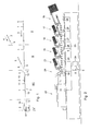
- Fig. 1 illustrates an example of the method according to the invention in four successive stages I, II, III and IV shown from right to left.
- two sheets 1, 2 of a first size and a second size are intended to be processed to a mail item.
- the sheet 1 of the first size is of A4 size and, according to this example, the sheet 2 is 12 cm long, measured in conveying direction.
- stage I the sheets 1, 2 are conveyed along a first conveyor track 5 and a second conveyor track 6 in conveying directions 3 and 4, respectively.
- stage II at least one of the sheets 1, 2 is stopped, until the relative positions of the sheets 1, 2 are suitable for combining the sheets 1, 2 to a stacked set 7 and then the sheets 1, 2 are simultaneously conveyed further and combined to a stacked set 7.
- stage III The condition in which the stacked set 7 has been formed is shown as stage III.
- the stacked set 7 is then folded twice to a zigzag structure, while, in both cases, a predetermined folding length ⁇ of 10 cm stored in a memory 8 of a control structure 9 (see Figures 2 and 3) is observed.
- a folding length is understood to mean the size in a direction perpendicular to the fold of a panel of a set of sheets adjoining the fold.
- the folding length is chosen such that the folded set fits, with a suitable play in a direction perpendicular to the folds, into an envelope into which the sheets are inserted after folding.
- at least one of the sheets of the set has one or more adhesive edges, such as a gummed edge, which are attached to one another during or after folding, so that the sheet forms the cover of the set.
- stage IV The condition of the set 7 processed according to this example after folding is shown as stage IV.
- the size in the conveying direction of the small sheet 2 supplied alon g the second conveyor track 6 has been inputted into the control structure. This size may, for instance, have been scanned during a startup stage prior to the operational stage in which mail items are actually assembled or may have been inputted manually via a user interface.
- the difference between the predetermined folding length ⁇ and the size of the sheet 2 of the second, smaller size is -2 cm according to this example. This value is within a predetermined range, for which it holds true that, during folding, there is an increased risk of disturbances if the sheet 2 of the second, smaller size is folded with a leading or trailing edge in alignment with the leading and trailing edge, respectively, of the sheet 1 of the first, larger size.
- the reason for this may, for instance, be that the panel to be folded of the sheet 2 of the second, smaller size is too small to be folded reliably by the folding station or that the length of the panel to be folded of the sheet 2 of the second, smaller size is such that, during folding, the free edge thereof strikes an arch of the sheet 1 of the first, larger size, or cannot be conveyed reliably.
- the conveying tracks 5, 6 have been controlled by the control structure 9 for combining the sheets 1, 2 to a set with leading edges 10, 11 at a mutual distance in the conveying direction 3 and with trailing edges 12, 13 at a mutual distance in the conveying direction 3.
- the mutual distance of the trailing edges 12, 13 of the sheets 1, 2 is 2 cm.
- the sheets 1, 2 of the set 7 are then, from the combining (stage III) to the folding of the set 7 (completed in stage IV), mutually fixed.
- a first fold 14 is provided in the two sheets 1, 2 of the set 7 and a second fold 15 is only provided in the sheet 1 of the first, larger size.
- the size of the smallest panel to be folded, measured perpendicular to the fold 14, is 4 cm, and not 2 cm as would be the case if the sheets 1, 2 were folded with aligned trailing edges 12, 13.
- the sheet 2 of the second, smaller size can reliably be folded along with the sheet 1 of the first, larger size. It is therefore not necessary to stack folded sheets with other sheets, folded or not, and only one folding stage is needed, even if the smaller sheet is to be folded as well.
- the sheets 1, 2, due to the fold 14 made in the set 7, are less easily movable relative to each other in conveying direction and the set can be driven by pushing the closed side of the fold 14, without the sheets 1, 2 thereby being moved relative to each other.
- the sheets when being combined into a set are preferably gathered such that the sheet of the first, larger size projects, at its leading and trailing ends, with respect to the sheet of the second, smaller size. Then, the total length in conveying direction of the collected set is not larger than the length in conveying direction of the sheet with the largest size in conveying direction.
- This relative positioning during combining is further particularly advantageous if the set contains only one sheet with a largest length in conveying direction and if this sheet is provided with adhesive edges, such as gummed edges. It can then be guaranteed reliably that the panels of the sheet or the sheets of the smaller size or the sheets of the smaller sizes do not cover the adhesive edges after folding and the sheet of the largest size can reliably be processed to an envelope enveloping the other sheet or the other sheets of the respective set.
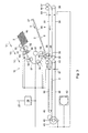
- FIG. 2 and 3 An example of an apparatus with which the method according to the above-described example can be carried out is shown in Figs. 2 and 3.
- This apparatus for assembling mail items is provided with a supply station 16 for supplying main documents, supply stations 17-20 for supplying attachments, a folding station 21 and an inserter station 22.
- the first conveyor track 5 extends from the supply station 16 for supplying main documents to the inserter station 22.
- the control structure 9 comprises a main control unit 24 with a memory 8 and a connecting structure 23 which operatively connects the main control unit 24 with the station 16-22, as Fig. 2 diagrammatically shows.
- the stations are provided with distributed control units 25-31 for processing instructions coming from the main control unit 24 and for delivering signals representing the status of the respective station 16-20.
- the supply stations 16-20 are each suitable for feeding multiple sheets to each set. However, the supply stations may also be arranged for each time feeding at most one sheet for each set 7 intended for a mail item.
- Fig. 3 shows the attachment supply station 19 of the apparatus according to Fig. 2 in more detail.
- the first conveyor track 5 for conveying sheets 1 is designed with pairs of opposite sets of conveyor belts 32, 33, 34, 35.
- the conveyor belts are each tensioned around end rollers 36-44.
- Tension rollers 44, 45 serve for tensioning the upper conveyor belts 33, 35.
- the opposite sets of conveyor belts 32-35 operatively ensure that sheets of sets 7 conveyed therebetween are mutually fixed in a reliable manner.
- the second conveyor track 6 converging with the first conveyor track 5 is determined by a collecting platform 46 with an adjustable end stop 47 and a pair of conveyor rollers 58 located downstream thereof.
- the means for piece by piece supplying sheets from a stock comprise a sheet holder 49, a supply roller 50 for supplying sheets, a conveyor roller 51 and a separation roller 52 for conveying and, if needed, separating sheets 2 supplied by a supply roller 50, two sets of conveyor rollers 53, 54, 55, 56 for conveying separated sheets at increasing speeds ⁇ 1, ⁇ 2, ⁇ 3 and a diagrammatically shown system of guides 57.
- the nip between the pair of conveyor rollers 58 downstream of the collecting platform forms the connection of the second conveyor track 6 to the first conveyor track 5 for each time combining sheets 1, 2 supplied via the first and second conveyor tracks 5, 6 to a stacked set 7.
- the means for supplying sheets 2 to the sheet platform 47 comprise a first attachment detector 59 for detecting the presence of a sheet 2 directly downstream of the nip between the conveyor roller pair 53.
- a coupling 60 operates the drive of the conveyor rollers 50, 51 and 53 upstream of the detector 60 by coupling or uncoupling the detector with or from a motor/pulse disc assembly 61, while the local control unit 28 is arranged for controlling the coupling for stopping sheets in a waiting position with a leading edge shortly beyond the first attachment detector 59 and for each time driving the conveyor rollers 50, 51 and 53 upstream of the detector 60, until the detector has detected and signaled the presence of a leading edge of a next sheet 2.
- the central control unit 24 is arranged for determining the folding length or folding lengths ⁇ of the set 7 to be folded and for storing data representing the size of the sheets 2 of the second, smaller size in the memory 8. Further, the central control unit 24 is arranged for, in response to the difference between the folding length or folding lengths ⁇ and the size of the second sheets which is within a predetermined range, signaling to the respective distributed control units 26-29 of the attachment supply stations 17-20 that, during the combining of sheets 1 and 2, supplied via the first and the second conveyor tracks 5, 6, to the set 7, leading edges 10, 11 of the sheets 1, 2 are to be positioned at a mutual distance in the conveying direction 3 and trailing edges of the sheets 1, 2 are to be positioned at a mutual distance in the conveying direction 3.
- the central control unit 24 does not position the sheets 2 of the second, smaller size with leading or trailing edges 11, 13 in alignment on the leading and trailing edges, respectively, of the sheets 1 of the first, larger size, depends on the specific properties of the specific properties of the folding station 21 with which the sets 7 are folded.
- the apparatus For controlled positioning of the sheets 2 of the second, smaller size with respect to the sheets 1 of the first, larger size in a position with both leading and trailing edges mutually staggered over (directly or indirectly) predetermined distances in conveying direction, the apparatus according to the example shown is designed as follows.
- a drive structure For driving the first conveyor track 5 in the area of the attachment supply station 19, a drive structure is provided, of which an AC motor 62 and a pulse disc 63 are part. Operating means for starting and stopping the first drive structure are formed by the local control unit 28. For this purpose, this is provided with a motor control. This can also be part of the drive structure.
- a track monitoring detector 64 For detecting at least one leading or trailing edge of a sheet 1 in the first conveyor track 5, a track monitoring detector 64 has been placed upstream of the area where the second conveyor track 6 connects to the first conveyor track 5.
- a second drive structure for driving the second conveyor track 6 is formed by the motor/pulse disc assembly 61 and a second coupling 65 with which the conveyor roller pair 58 downstream of the collecting platform can be coupled with and uncoupled from the motor/pulse disc assembly 61.
- the local control unit 28 is further arranged for starting and stopping the second drive structure, and in particular the conveyor roller pair 58 downstream of the collecting platform 46, by operating the second coupling 65.
- a second attachment detector 66 for detecting at least one leading or trailing edge of a sheet 2 in the second conveyor track 6 is located just downstream of the conveyor roller pair 58 downstream of the collecting platform 46.
- the local control unit 28 is arranged for releasing the second conveyor track 6 and for controlling the second coupling 65 for starting the drive of the second conveyor track 6 by coupling and for starting the motor 62 for driving the first conveyor track 5.
- sheets 1 and 2 are supplied along the first and second conveyor tracks 5, 6.
- the local control unit 28 is further arranged for then, in response to detection of a leading or trailing edge 11 or 13 of a sheet 2 in the second conveyor track 6, controlling the second coupling 65 for interrupting the drive of the second conveyor track 6 by uncoupling.
- the sheet in the second conveyor track 6 is stopped in a known waiting position.
- the local control unit 28 is further arranged for then, in response to detection of a leading or trailing edge 10 or 12 of a sheet by the detector 64 along the first conveyor track 5, controlling the second coupling 65 for restarting the drive of the second conveyor track 6 by recoupling. Because the distances from the detector 64 along the first conveyor track 5 and the distance from the second attachment detector 66 along the second conveyor track 6 and from the stop 47 to the place where the second conveyor track 6 converges with the first conveyor track 5 are known, by carrying out the restart of the drive of the second conveyor track 6 at a suitable time, the second sheet 2 can accurately be positioned in any desired position on the first sheet 1.
- a downstream detector 67 is located for detecting the trailing edge 12 of a set 7 gathered in the attachment supply station 19.
- the local control unit 28 is arranged for stopping the motor 62 which drives the first conveyor track 5 in response to a signal from the detector 67 which indicates the passage of such a trailing edge 12.
- Detection Action ready signal (for instance coming from downstream station 20) coupling 65 IN, motor 62 ON leading edge of sheet 2 at detector; second attachment detector 66 coupling 65 FREE trailing edge at detector 64 start counting pulses by pulse disc 3 pulse counting has reached predetermined value coupling 65 IN trailing edge at detector 67 coupling 65 FREE, motor 62 OFF
- the pulse disc 63 thus forms a movement indicator coupled with the local control unit 28 of the control structure 9 for detecting movement in conveying direction by the first conveyor track 5.
- the local control unit 28 is here arranged for restarting the second conveyor track 6 in response to a particular movement indicated by the movement indicator 63, which movement has been chosen such that the sheet 2 of the second size is positioned in the intended position in conveying direction on the sheet 1 of the first size.
- it is preferred to stop or at least decelerate the second conveyor track until the intended relative positioning of the sheets 1, 2 has been obtained it is also possible to stop or decelerate the first conveyor track 5 for obtaining the intended relative positions.
Landscapes
- Folding Of Thin Sheet-Like Materials, Special Discharging Devices, And Others (AREA)
Abstract
Description
| Detection | Action | |
| ready signal (for instance coming from downstream station 20) | | |
| leading edge of | | |
| trailing edge at | start counting pulses by | |
| pulse counting has reached | coupling | 65 IN |
| trailing edge at | |
Claims (6)
- A method for processing sheets (1, 2) with different sizes to a mail item, comprising:wherein said at least one sheet (1) of the first size has a size in conveying direction (3) which differs from the size in conveying direction (4) of said at least one sheet (2) of the second size;conveying at least one sheet (1) of a first size along a first conveyor track (5);conveying at least one sheet (2) of a second size along a second conveyor track (6) converging with said first conveyor track (5);combining the at least one sheet (1) of the first size and the at least one sheet (2) of the second size to a stacked set (7);folding the stacked set (7) with at least one predetermined folding length (a) stored in a memory (8) of a control structure (9);
wherein at least the size in said conveying direction (4) of said at least one sheet (2) of the second size is inputted into the control structure (9);
wherein, in response to a difference between said at least one folding length (a) and said size of the sheet (2) of the second size, which is within a predetermined range, said conveyor tracks (5, 6) are controlled by the control structure (9) for combining at least said sheets (1, 2) with leading edges (10, 11) at a mutual distance in said conveying direction (3) and with trailing edges (12, 13) at a mutual distance in said conveying direction (3) to form the set (7);
wherein said sheets (1, 2) are mutually fixed from the combining until the folding; and
wherein, during the folding, at least one fold (14) is provided in both sheets (1, 2). - A method according to claim 1, wherein said at least one fold (14) is provided in said sheets (1, 2) at the same time.
- A method according to claim 1 or 2, wherein said sheets (1, 2) are inserted into an envelope.
- An apparatus for assembling mail items comprising sheets (1, 2) with different sizes, comprising:a first conveyor track (5) for conveying sheets (1);a second conveyor track (6) converging with said first conveyor track (5) for conveying sheets (2);a connection of the second conveyor track (6) to the first conveyor track (5) for each time combining at least one sheet (1) supplied via the first conveyor track (5) and at least one sheet (2) supplied via the second conveyor track (6) to form a stacked set (7);a folding station (21) downstream of said connection for folding supplied sets (7) with at least one predetermined folding length (a); anda control structure (9) for determining the at least one folding length (a) of the set (7) to be folded and for controlling the first and second conveyor tracks (5, 6) such that, in response to a difference between said at least one folding length (a) and the size in conveying direction of the sheet (2) conveyed along the second conveyor track (6), which is within a predetermined range, the conveyor tracks (5, 6) are controlled by the control structure (9) for combining at least said sheets (1, 2) with leading edges (10, 11) at a mutual distance in conveying direction (3) and with trailing edges (12, 13) at a mutual distance in conveying direction (3) to form the set (7).
- An apparatus according to claim 4, comprising:wherein said control structure (9) is arranged for starting the first and second drive structures, for then stopping at least the first or the second drive structure in response to detection of a leading or trailing edge of a sheet (1, 2) in the first or second conveyor track (5, 6), respectively, and for then restarting at least the first or the second drive structure, respectively, in response to detection of a leading or trailing edge of a sheet in the second or the first conveyor track (6, 5), respectively.a first drive structure (62) for driving the first conveyor track (5);a first detector (64) for detecting at least one leading or trailing edge (10, 12) of a sheet (1) in the first conveyor track (5);a second drive structure (61, 65) for driving the second conveyor track (6); anda second detector (66) for detecting at least one leading or trailing edge (11, 13) of a sheet (2) in the second conveyor track (6);
- An apparatus according to claim 5, further comprising a movement indicator (63) coupled with the control structure (9) for detecting movement in conveying direction by the first or second conveyor track (5, 6), wherein the control structure (9) is arranged for restarting the second or the first conveyor track (6), respectively, in response to a particular movement indicated by said movement indicator (63).
Applications Claiming Priority (2)
| Application Number | Priority Date | Filing Date | Title |
|---|---|---|---|
| NL1025160 | 2003-12-31 | ||
| NL1025160A NL1025160C2 (en) | 2003-12-31 | 2003-12-31 | Method and device for processing sheets of different sizes into a postal item. |
Publications (2)
| Publication Number | Publication Date |
|---|---|
| EP1550628A1 true EP1550628A1 (en) | 2005-07-06 |
| EP1550628B1 EP1550628B1 (en) | 2008-02-13 |
Family
ID=34568038
Family Applications (1)
| Application Number | Title | Priority Date | Filing Date |
|---|---|---|---|
| EP04078571A Expired - Fee Related EP1550628B1 (en) | 2003-12-31 | 2004-12-30 | Method and apparatus for processing sheets of different sizes to a mail item |
Country Status (4)
| Country | Link |
|---|---|
| US (1) | US8544242B2 (en) |
| EP (1) | EP1550628B1 (en) |
| DE (1) | DE602004011746T2 (en) |
| NL (1) | NL1025160C2 (en) |
Cited By (6)
| Publication number | Priority date | Publication date | Assignee | Title |
|---|---|---|---|---|
| EP1739044A1 (en) * | 2005-06-30 | 2007-01-03 | Neopost S.A. | Apparatus and method for collecting sheets into sets |
| EP1803585A1 (en) * | 2005-12-31 | 2007-07-04 | Neopost Technologies SA | Inserter having a motor and a controlled coupling |
| EP1942464A1 (en) | 2006-12-29 | 2008-07-09 | Neopost Technologies | Method and apparatus for collating postal items |
| EP2444325A1 (en) * | 2010-10-25 | 2012-04-25 | Mathias Bäuerle GmbH | Method and device for producing mail pieces |
| EP1762525B2 (en) † | 2005-09-12 | 2013-01-23 | Müller Martini Holding AG | Device for collating or gathering of printed products |
| EP3269670A1 (en) * | 2016-07-13 | 2018-01-17 | Müller Martini Holding AG | Method and device for forming advertising material compositions |
Families Citing this family (13)
| Publication number | Priority date | Publication date | Assignee | Title |
|---|---|---|---|---|
| US11297984B2 (en) | 2006-10-31 | 2022-04-12 | Gpcp Ip Holdings Llc | Automatic napkin dispenser |
| DE502007003959D1 (en) * | 2007-10-19 | 2010-07-08 | Mueller Martini Holding Ag | Device for collecting printed sheets |
| US7930869B2 (en) * | 2007-12-21 | 2011-04-26 | Pitney Bowes Inc. | Inserter control method |
| US8074957B2 (en) | 2008-09-25 | 2011-12-13 | Prime Forming & Construction Supplies, Inc. | Formliner and method of use |
| US10383489B2 (en) * | 2012-02-10 | 2019-08-20 | Gpcp Ip Holdings Llc | Automatic napkin dispenser |
| DE102013111843B4 (en) | 2013-10-28 | 2015-08-06 | Böwe Systec Gmbh | Method and device for processing goods to a mail item |
| DE202013104806U1 (en) | 2013-10-28 | 2015-01-30 | Böwe Systec Gmbh | Device for processing goods to a mail item |
| CH709674A1 (en) | 2014-05-20 | 2015-11-30 | Ferag Ag | A process for preparing collections of a plurality of different printing products, and device for carrying out the method. |
| USD791364S1 (en) | 2014-09-25 | 2017-07-04 | Prime Forming & Construction Supplies, Inc. | Formliner |
| US20160237704A1 (en) | 2015-02-14 | 2016-08-18 | Prime Forming & Construction Supplies, Inc., dba Fitzgerald Formliners | Formliners and methods of use |
| US20170101284A1 (en) * | 2015-10-07 | 2017-04-13 | Océ-Technologies B.V. | Printing system with sheet inserter |
| CN108602199B (en) | 2015-12-28 | 2020-10-27 | 初级模具和建筑用品公司 | Stencil pads for forming patterns in curable materials and methods of using the same |
| EP3348417A1 (en) * | 2017-01-13 | 2018-07-18 | Neopost Technologies | Cold seal paper apparatus and method for manufacturing mailpieces |
Citations (9)
| Publication number | Priority date | Publication date | Assignee | Title |
|---|---|---|---|---|
| US3966186A (en) * | 1971-11-02 | 1976-06-29 | F. L. Smithe Machine Company, Inc. | Method and apparatus for feeding inserts selectively |
| US4694632A (en) * | 1985-06-24 | 1987-09-22 | Gunther International, Ltd. | Mechanism for folding an envelope around an insert |
| US5064115A (en) * | 1990-08-06 | 1991-11-12 | Wallace Computer Services, Inc. | Mailer and method and apparatus for making |
| EP0498515A1 (en) * | 1991-02-08 | 1992-08-12 | Hadewe B.V. | Method and means for setting a folding station |
| EP0556922A1 (en) * | 1992-02-18 | 1993-08-25 | Hadewe B.V. | A method for assembling a postal item as well as a system and an aligning station for carrying out this method |
| EP0605066A1 (en) * | 1992-12-31 | 1994-07-06 | Hadewe B.V. | Apparatus and method for preparing sets of documents to be mailed |
| NL9301296A (en) * | 1993-07-23 | 1995-02-16 | Berthom Mail Systems Benelux B | Method and device for making and filling an envelope |
| US6266944B1 (en) * | 1996-08-19 | 2001-07-31 | R.C.P. Di Riccardo Consiglio | Machine and process for the automatic enveloping of messages with a variable number of sheets |
| US6558054B2 (en) * | 1998-04-22 | 2003-05-06 | Haller Juerg Paul | Method for manufacturing mailing-ready printed products and envelopes for use with such method |
Family Cites Families (30)
| Publication number | Priority date | Publication date | Assignee | Title |
|---|---|---|---|---|
| US3579947A (en) * | 1969-04-07 | 1971-05-25 | Goodway Inc | Method of printing and folding a mailing piece |
| US3961781A (en) * | 1969-11-03 | 1976-06-08 | R. Funk & Co., Inc. | Foldable-sheet processing systems |
| US4071997A (en) * | 1976-04-27 | 1978-02-07 | Gunther Business Systems, Inc. | Mechanism and method of making an envelope |
| US4575067A (en) * | 1984-12-10 | 1986-03-11 | Rca Corporation | Collating machine stacking bin insert |
| DE3502896A1 (en) * | 1985-01-29 | 1986-07-31 | Hagen 8021 Icking Gämmerler | METHOD AND DEVICE FOR COMBINING AT LEAST TWO FLOWS OF DOMESTICALLY-LAYING PRODUCTS, IN PARTICULAR FOLDED PAPER PRODUCTS |
| IT1207630B (en) * | 1987-03-09 | 1989-05-25 | Cestind Centro Studi Ind | EQUIPMENT FOR SET-UP IN THE DISPOSAL PACKAGING ARRANGEMENT OF DISPOSABLE FILTER BAGS IN CONTINUOUS PACKAGING MACHINES OF SAID FILTER BAGS |
| US4784379A (en) * | 1987-03-24 | 1988-11-15 | Bell & Howell Company | Apparatus and method for automated mail |
| US4972655A (en) * | 1987-06-30 | 1990-11-27 | Iseto Shiko Co., Ltd. | Apparatus for manufacturing sealed postal mails or the like envelope assemblies |
| US4875668A (en) * | 1988-04-28 | 1989-10-24 | Computer Output Processors And Engineering, Inc. | High speed sheet folder and presser for automated mailing systems |
| NL9001798A (en) * | 1990-08-10 | 1992-03-02 | Oce Nederland Bv | DEVICE FOR FOLDING AND COLLECTING SHEETS OF DIFFERENT SIZES. |
| US5207412A (en) * | 1991-11-22 | 1993-05-04 | Xerox Corporation | Multi-function document integrater with control indicia on sheets |
| US5316279A (en) * | 1993-01-04 | 1994-05-31 | Xerox Corporation | Copier/printer job stacking with discrete cover sheets with extending printed banners |
| US5568717A (en) * | 1993-03-30 | 1996-10-29 | Moore Business Forms, Inc. | Forming an envelope around inserts |
| US5445368A (en) * | 1993-10-27 | 1995-08-29 | Pitney Bowes Inc. | Apparatus and method for forming collations of two different size documents |
| DE4407871C2 (en) * | 1994-03-04 | 1997-08-21 | Francotyp Postalia Gmbh | Arrangement for the controllable optional feeding of filling material to an inserting device |
| US5848346A (en) * | 1994-08-08 | 1998-12-08 | Canon Kabushiki Kaisha | Image forming apparatus for offsetting output sheet |
| US5514066A (en) * | 1994-09-01 | 1996-05-07 | Pitney Bowes Inc. | Buckle chute folding machine for different length sheets |
| US5573232A (en) * | 1995-06-09 | 1996-11-12 | Ifkovits; Edward M. | Parallel sheet processing apparatus |
| US5980439A (en) * | 1996-01-19 | 1999-11-09 | Output Technology Solutions Of California, Inc. | Folding apparatus |
| US5816773A (en) * | 1996-01-19 | 1998-10-06 | International Billing Services, Inc. | Collator apparatus |
| US5829953A (en) * | 1996-01-19 | 1998-11-03 | International Billing Services, Inc. | Billing statement system |
| US5681035A (en) * | 1996-09-12 | 1997-10-28 | Pitney Bowes Inc. | In-line burster for inserting system |
| FR2782673B1 (en) * | 1998-09-02 | 2000-11-24 | Neopost Ind | FOLDER / INSERTER WITH SEPARATE INSERT PATH |
| NL1013084C2 (en) * | 1999-09-17 | 2001-03-20 | Neopost Bv | Establish a system for assembling mail items. |
| JP3999202B2 (en) * | 2001-12-21 | 2007-10-31 | フェラーク・アクチェンゲゼルシャフト | Method and apparatus for forming a group of flat articles |
| US7100911B2 (en) * | 2002-02-07 | 2006-09-05 | Bowe Bell + Howell Company | Method and apparatus for assembling a stack of sheet articles from multiple input paths |
| JP3887251B2 (en) * | 2002-03-14 | 2007-02-28 | ニスカ株式会社 | Sheet post-processing apparatus and image forming apparatus |
| JP4663571B2 (en) * | 2005-06-10 | 2011-04-06 | キヤノン株式会社 | Sheet stacking apparatus, sheet processing apparatus, and image forming apparatus |
| JP4528674B2 (en) * | 2005-06-15 | 2010-08-18 | ニスカ株式会社 | Bookbinding apparatus and image forming apparatus using the same |
| JP4290176B2 (en) * | 2006-05-10 | 2009-07-01 | ホリゾン・インターナショナル株式会社 | How to create a saddle-stitched booklet with small paper inserted |
-
2003
- 2003-12-31 NL NL1025160A patent/NL1025160C2/en not_active IP Right Cessation
-
2004
- 2004-12-30 EP EP04078571A patent/EP1550628B1/en not_active Expired - Fee Related
- 2004-12-30 DE DE602004011746T patent/DE602004011746T2/en active Active
- 2004-12-31 US US11/026,311 patent/US8544242B2/en active Active
Patent Citations (9)
| Publication number | Priority date | Publication date | Assignee | Title |
|---|---|---|---|---|
| US3966186A (en) * | 1971-11-02 | 1976-06-29 | F. L. Smithe Machine Company, Inc. | Method and apparatus for feeding inserts selectively |
| US4694632A (en) * | 1985-06-24 | 1987-09-22 | Gunther International, Ltd. | Mechanism for folding an envelope around an insert |
| US5064115A (en) * | 1990-08-06 | 1991-11-12 | Wallace Computer Services, Inc. | Mailer and method and apparatus for making |
| EP0498515A1 (en) * | 1991-02-08 | 1992-08-12 | Hadewe B.V. | Method and means for setting a folding station |
| EP0556922A1 (en) * | 1992-02-18 | 1993-08-25 | Hadewe B.V. | A method for assembling a postal item as well as a system and an aligning station for carrying out this method |
| EP0605066A1 (en) * | 1992-12-31 | 1994-07-06 | Hadewe B.V. | Apparatus and method for preparing sets of documents to be mailed |
| NL9301296A (en) * | 1993-07-23 | 1995-02-16 | Berthom Mail Systems Benelux B | Method and device for making and filling an envelope |
| US6266944B1 (en) * | 1996-08-19 | 2001-07-31 | R.C.P. Di Riccardo Consiglio | Machine and process for the automatic enveloping of messages with a variable number of sheets |
| US6558054B2 (en) * | 1998-04-22 | 2003-05-06 | Haller Juerg Paul | Method for manufacturing mailing-ready printed products and envelopes for use with such method |
Cited By (9)
| Publication number | Priority date | Publication date | Assignee | Title |
|---|---|---|---|---|
| EP1739044A1 (en) * | 2005-06-30 | 2007-01-03 | Neopost S.A. | Apparatus and method for collecting sheets into sets |
| NL1029387C2 (en) * | 2005-06-30 | 2007-01-04 | Neopost Sa | Device and method for collecting sheets into sets. |
| US7588237B2 (en) | 2005-06-30 | 2009-09-15 | Neopost Technologies | Apparatus and method for collecting sheets into sets |
| EP1762525B2 (en) † | 2005-09-12 | 2013-01-23 | Müller Martini Holding AG | Device for collating or gathering of printed products |
| EP1803585A1 (en) * | 2005-12-31 | 2007-07-04 | Neopost Technologies SA | Inserter having a motor and a controlled coupling |
| EP1942464A1 (en) | 2006-12-29 | 2008-07-09 | Neopost Technologies | Method and apparatus for collating postal items |
| EP2444325A1 (en) * | 2010-10-25 | 2012-04-25 | Mathias Bäuerle GmbH | Method and device for producing mail pieces |
| EP3269670A1 (en) * | 2016-07-13 | 2018-01-17 | Müller Martini Holding AG | Method and device for forming advertising material compositions |
| US10940714B2 (en) | 2016-07-13 | 2021-03-09 | Mueller Martini Holding Ag | Method and apparatus for forming advertising media compilations |
Also Published As
| Publication number | Publication date |
|---|---|
| DE602004011746D1 (en) | 2008-03-27 |
| US8544242B2 (en) | 2013-10-01 |
| DE602004011746T2 (en) | 2009-02-19 |
| US20050184441A1 (en) | 2005-08-25 |
| NL1025160C2 (en) | 2005-07-04 |
| EP1550628B1 (en) | 2008-02-13 |
Similar Documents
| Publication | Publication Date | Title |
|---|---|---|
| EP1550628B1 (en) | Method and apparatus for processing sheets of different sizes to a mail item | |
| US5518121A (en) | Method for automated mail extraction and remittance processing | |
| US6644657B2 (en) | Accumulator having power ramp | |
| JP2014208558A (en) | Carrier device for envelope and related method | |
| JPH08509945A (en) | Document handling system | |
| US5183246A (en) | Diverting apparatus and method for in-line inserting equipment | |
| US6547078B1 (en) | Automated mail extraction and remittance processing | |
| US6386537B1 (en) | Sheet accumulator with diverting mechanisms | |
| US5297783A (en) | Apparatus and system for handling cut sheets and web forms to form discrete batches | |
| US5842693A (en) | Automated mail extraction and remittance processing | |
| US6179288B1 (en) | Envelope reorientation device | |
| EP1739044B1 (en) | Apparatus and method for collecting sheets into sets | |
| US6776406B2 (en) | Feeder and separator for separating and moving sheets from a stack of sheets | |
| JP3659277B2 (en) | Collating and sealing device | |
| CA2472870C (en) | Apparatus and method for accumulating sheets | |
| US8172216B2 (en) | Apparatus and method for gathering documents | |
| US7011304B2 (en) | Collator apparatus | |
| JP2009298572A (en) | Gluing device of paper and gluing method | |
| US20030080486A1 (en) | Inserting machine with interchangeable modules | |
| JP3689839B2 (en) | Paper sheet delivery system | |
| JPS591748Y2 (en) | Paper sheet bundle sorting device | |
| JPS6371040A (en) | Paper sheet disposing device | |
| JPH0530041U (en) | Continuous paper feeder | |
| JP2005119830A (en) | Document feeder | |
| JP2002173235A (en) | Paper feeder |
Legal Events
| Date | Code | Title | Description |
|---|---|---|---|
| PUAI | Public reference made under article 153(3) epc to a published international application that has entered the european phase |
Free format text: ORIGINAL CODE: 0009012 |
|
| AK | Designated contracting states |
Kind code of ref document: A1 Designated state(s): AT BE BG CH CY CZ DE DK EE ES FI FR GB GR HU IE IS IT LI LT LU MC NL PL PT RO SE SI SK TR |
|
| AX | Request for extension of the european patent |
Extension state: AL BA HR LV MK YU |
|
| 17P | Request for examination filed |
Effective date: 20050805 |
|
| AKX | Designation fees paid |
Designated state(s): DE FR GB |
|
| GRAP | Despatch of communication of intention to grant a patent |
Free format text: ORIGINAL CODE: EPIDOSNIGR1 |
|
| GRAS | Grant fee paid |
Free format text: ORIGINAL CODE: EPIDOSNIGR3 |
|
| GRAA | (expected) grant |
Free format text: ORIGINAL CODE: 0009210 |
|
| AK | Designated contracting states |
Kind code of ref document: B1 Designated state(s): DE FR GB |
|
| REG | Reference to a national code |
Ref country code: GB Ref legal event code: FG4D |
|
| REF | Corresponds to: |
Ref document number: 602004011746 Country of ref document: DE Date of ref document: 20080327 Kind code of ref document: P |
|
| ET | Fr: translation filed | ||
| PLBE | No opposition filed within time limit |
Free format text: ORIGINAL CODE: 0009261 |
|
| STAA | Information on the status of an ep patent application or granted ep patent |
Free format text: STATUS: NO OPPOSITION FILED WITHIN TIME LIMIT |
|
| 26N | No opposition filed |
Effective date: 20081114 |
|
| REG | Reference to a national code |
Ref country code: FR Ref legal event code: PLFP Year of fee payment: 12 |
|
| REG | Reference to a national code |
Ref country code: DE Ref legal event code: R082 Ref document number: 602004011746 Country of ref document: DE Representative=s name: CBDL PATENTANWAELTE, DE |
|
| REG | Reference to a national code |
Ref country code: DE Ref legal event code: R082 Ref document number: 602004011746 Country of ref document: DE Representative=s name: CBDL PATENTANWAELTE, DE Ref country code: DE Ref legal event code: R081 Ref document number: 602004011746 Country of ref document: DE Owner name: NEOPOST TECHNOLOGIES S.A., FR Free format text: FORMER OWNER: NEOPOST S.A., BAGNEUX, FR |
|
| REG | Reference to a national code |
Ref country code: FR Ref legal event code: PLFP Year of fee payment: 13 |
|
| REG | Reference to a national code |
Ref country code: FR Ref legal event code: PLFP Year of fee payment: 14 |
|
| PGFP | Annual fee paid to national office [announced via postgrant information from national office to epo] |
Ref country code: GB Payment date: 20211221 Year of fee payment: 18 Ref country code: FR Payment date: 20211224 Year of fee payment: 18 Ref country code: DE Payment date: 20211210 Year of fee payment: 18 |
|
| REG | Reference to a national code |
Ref country code: DE Ref legal event code: R082 Ref document number: 602004011746 Country of ref document: DE Representative=s name: CBDL PATENTANWAELTE GBR, DE |
|
| REG | Reference to a national code |
Ref country code: DE Ref legal event code: R119 Ref document number: 602004011746 Country of ref document: DE |
|
| GBPC | Gb: european patent ceased through non-payment of renewal fee |
Effective date: 20221230 |
|
| PG25 | Lapsed in a contracting state [announced via postgrant information from national office to epo] |
Ref country code: GB Free format text: LAPSE BECAUSE OF NON-PAYMENT OF DUE FEES Effective date: 20221230 Ref country code: DE Free format text: LAPSE BECAUSE OF NON-PAYMENT OF DUE FEES Effective date: 20230701 |
|
| PG25 | Lapsed in a contracting state [announced via postgrant information from national office to epo] |
Ref country code: FR Free format text: LAPSE BECAUSE OF NON-PAYMENT OF DUE FEES Effective date: 20221231 |