EP1547271B1 - DEVICE and method FOR TRANSMITTING DIGITAL SIGNALS BETWEEN MOBILE UNITS WITH AN ADAPTATION OF THE SPECTRAL CHARACTERISTICS - Google Patents
DEVICE and method FOR TRANSMITTING DIGITAL SIGNALS BETWEEN MOBILE UNITS WITH AN ADAPTATION OF THE SPECTRAL CHARACTERISTICS Download PDFInfo
- Publication number
- EP1547271B1 EP1547271B1 EP03757874A EP03757874A EP1547271B1 EP 1547271 B1 EP1547271 B1 EP 1547271B1 EP 03757874 A EP03757874 A EP 03757874A EP 03757874 A EP03757874 A EP 03757874A EP 1547271 B1 EP1547271 B1 EP 1547271B1
- Authority
- EP
- European Patent Office
- Prior art keywords
- signals
- receiver
- data
- transmission
- unit
- Prior art date
- Legal status (The legal status is an assumption and is not a legal conclusion. Google has not performed a legal analysis and makes no representation as to the accuracy of the status listed.)
- Expired - Lifetime
Links
- 230000003595 spectral effect Effects 0.000 title claims abstract description 14
- 238000000034 method Methods 0.000 title claims description 3
- 230000006978 adaptation Effects 0.000 title description 4
- VJYFKVYYMZPMAB-UHFFFAOYSA-N ethoprophos Chemical group CCCSP(=O)(OCC)SCCC VJYFKVYYMZPMAB-UHFFFAOYSA-N 0.000 title 1
- 230000005540 biological transmission Effects 0.000 claims abstract description 50
- 239000004020 conductor Substances 0.000 claims description 15
- 230000007423 decrease Effects 0.000 claims description 3
- 238000012545 processing Methods 0.000 claims description 3
- 238000005259 measurement Methods 0.000 claims 2
- 238000011084 recovery Methods 0.000 claims 1
- 230000008878 coupling Effects 0.000 description 5
- 238000010168 coupling process Methods 0.000 description 5
- 238000005859 coupling reaction Methods 0.000 description 5
- 230000036039 immunity Effects 0.000 description 5
- 238000006243 chemical reaction Methods 0.000 description 4
- 230000001419 dependent effect Effects 0.000 description 3
- 230000008929 regeneration Effects 0.000 description 3
- 238000011069 regeneration method Methods 0.000 description 3
- 230000004044 response Effects 0.000 description 3
- 230000036962 time dependent Effects 0.000 description 3
- 238000012937 correction Methods 0.000 description 2
- 230000003247 decreasing effect Effects 0.000 description 2
- 230000002829 reductive effect Effects 0.000 description 2
- 238000001228 spectrum Methods 0.000 description 2
- 230000009471 action Effects 0.000 description 1
- 230000003044 adaptive effect Effects 0.000 description 1
- 238000002591 computed tomography Methods 0.000 description 1
- 238000013461 design Methods 0.000 description 1
- 238000011161 development Methods 0.000 description 1
- 230000018109 developmental process Effects 0.000 description 1
- 230000002349 favourable effect Effects 0.000 description 1
- 230000006872 improvement Effects 0.000 description 1
- 230000001939 inductive effect Effects 0.000 description 1
- 230000007246 mechanism Effects 0.000 description 1
- 230000005855 radiation Effects 0.000 description 1
- 230000000717 retained effect Effects 0.000 description 1
- 230000002441 reversible effect Effects 0.000 description 1
- 238000010079 rubber tapping Methods 0.000 description 1
- 230000008054 signal transmission Effects 0.000 description 1
- 238000012546 transfer Methods 0.000 description 1
Images
Classifications
-
- H—ELECTRICITY
- H04—ELECTRIC COMMUNICATION TECHNIQUE
- H04B—TRANSMISSION
- H04B5/00—Near-field transmission systems, e.g. inductive or capacitive transmission systems
- H04B5/70—Near-field transmission systems, e.g. inductive or capacitive transmission systems specially adapted for specific purposes
- H04B5/72—Near-field transmission systems, e.g. inductive or capacitive transmission systems specially adapted for specific purposes for local intradevice communication
-
- H—ELECTRICITY
- H04—ELECTRIC COMMUNICATION TECHNIQUE
- H04L—TRANSMISSION OF DIGITAL INFORMATION, e.g. TELEGRAPHIC COMMUNICATION
- H04L25/00—Baseband systems
- H04L25/02—Details ; arrangements for supplying electrical power along data transmission lines
- H04L25/0264—Arrangements for coupling to transmission lines
- H04L25/0266—Arrangements for providing Galvanic isolation, e.g. by means of magnetic or capacitive coupling
Definitions
- the invention relates to rotary transformer for transmitting digital signals between a plurality of mutually rotatably movable units.
- a conductor structure in the first unit and a corresponding tap in the second unit is usually provided.
- ladder structures refers to all conceivable forms of conductor structures which are suitable for carrying electrical signals. This also applies to the known contacting sliding tracks or slip rings.
- the signal can optionally be coupled out galvanically or in the near field of the conductor structures.
- the coupling factor of the signal between the two units depends essentially on the distance of the two units from each other. Especially with spatially extended transmission systems and in particular at high speeds of movement can not be determined arbitrarily exactly due to mechanical tolerances, the distances between the moving units. These may in practice vary in a range from a direct touch to a few centimeters distance, preferably between .01 mm and 10 mm. Therefore, the coupling factor often varies with the position of the two units to each other, the speed (eg, by causing vibrations), and other factors. At the same time, the signal amplitude at the input of the receiver changes. This results With conventionally designed receivers, changes in the signal, which manifest themselves as increased jitter or even bit errors, for example. Likewise, this results in changes in immunity to interference.
- DE 196 44 503 A1 discloses a rotary coupling in which the frequency response of the signal to be transmitted is adapted to the transmission characteristics of the coupling device.
- the disadvantage of the prior art devices is still insufficient immunity to interference.
- the transmission signal levels can be increased in the line to improve immunity to interference. But this also increases the unwanted emission of high-frequency signals.
- the transmission signal level is reduced, the radiation decreases, but the immunity to interspersed interference from the outside also decreases.
- a device is used to transmit digital signals between at least two mutually rotatable units, preferably as a rotary transformer, as they are used for example in computer tomography.
- one or more units can be arranged on each side of the movement.
- the first unit is associated with a data source (1) for generating a serial data stream, such as a prior art parallel / serial converter.
- a transmitter (2) is provided, which generates electrical signals for transmission via a transmission conductor structure (3) from the serial data stream of the data source.
- the second unit is associated with a receiving antenna (4) for picking up electrical signals in the near field of the transmission line structure.
- the electrical signals of the receiving antenna are fed via a receiver (5) of a data sink (6) for further processing of the signals.
- an encoding device (7) is now provided between the data source (1) and the transmitter (2).
- This coding device is designed such that it implements the digital coding of the data stream in such a way that the data can be transmitted with minimal errors via transmitter (2), transmitter conductor structure (3), receiver antenna (4) and receiver (5).
- the coding device is provided in the electrical signal path between the data source (1) and transmitter (2).
- this coding device can also be arranged in the transmitter (2).
- the second unit between receiver (5) and data sink (6) is assigned a decoding device (9) for decoding the signals encoded by the coding device (7).
- the decoding of the coding device is reversed again, so that the signals supplied to the data sink correspond to the data stream of the data source (1).
- the decoder can also be arranged in the receiver (5).
- the coding for the optimal transport of data on the data path for data source or data sink is completely transparent.
- the coding of the data stream by means of the coding device (7) implements a conversion of the spectral properties of the data stream. This is done the coding such that the power of the signal in predetermined spectral ranges is selectively increased or decreased.
- the transmission quality can be adapted to the frequency response of the remaining transmission path and to existing interferers or interference-sensitive components.
- the coding can now advantageously be designed such that this frequency range is not used for the transmission.
- a maximum in these frequency ranges can be set at frequency ranges of particularly low attenuation by suitable coding.
- the coding is advantageously carried out in such a way that optionally these frequency ranges are omitted.
- a particularly high amplitude could be emitted in these frequency ranges.
- the coding of the spectrum of the transmitted signal can be adjusted such that only low signal levels are emitted in the frequency ranges of high susceptibility to interference.
- the known line spectrum of digital signals by a suitable coding be widened to comply with the limits measured according to the common EMC standards.
- the coding is advantageously carried out in such a way that the transmitted signal is DC-free.
- the type of coding is dynamically adjustable so that it can advantageously adapt to changes caused by the movement.
- a control unit is advantageously provided with means for determining the current operating state and a corresponding specification of the coding to the coding device.
- the coding can be specified position-dependent.
- a position sensor could signal the relative position of the mutually rotatable parts and specify a corresponding coding.
- a time-dependent coding can be specified. This is particularly advantageous at a constant rotational speed, as here again an assignment to the position is possible.
- the invention provides that the coding function of the coding device is varied in a time-dependent manner in order to compensate for the influences of time-dependent interferers.
- the coding can be adjusted according to the interference peaks of a power supply, an X-ray tube or an electric motor.
- the invention provides that the coding function of the coding device in Depending on electrical parameters is adjusted.
- a measured variable corresponding to a noise level of the transmission device can be determined.
- This measured variable can now optionally be used analogously to the adaptation of certain spectral components in such a way that the spectral components of the useful signal transmitted in the disturbed frequency ranges are raised in their amplitude.
- this parameter can be used to signal a shift of the spectral components of the useful signal in undisturbed areas.
- the measured variable can be used to trigger a changeover of another spectral amplitude distribution of the useful signal.
- a dynamic adaptation can take place at the beginning of a transmission, wherein during the transmission period the adjustments or adjustments made at the beginning are retained. Likewise, however, a dynamic adaptation during the entire transmission period is possible.
- the coding device is designed such that it introduces additional redundancy in the data stream. This additional redundancy allows further corrections to the information of the data stream in case of transmission errors. These corrections can now be made optionally by the data sink, but preferably by a decoding device.
- the coding device is designed such that it increases the data rate of the serial data stream and thus creates space for additional redundant information.
- a conversion of the data rate or alternatively a previously described implementation of the coding or the packet information by conversion of the serial data stream of the data sources in parallel data words, which can be easily modified, and the subsequent conversion into a modified serial data stream for transmission.
- a further device has an encoding device which encodes or encrypts the signals to be transmitted in order to increase security. Depending on the security requirements, a shorter or longer key may be used. According to the means for decryption can be provided either in the data sink or in the decoder.
- means for clock regeneration are optionally provided in the coding device (7) or in the decoding device (8).
- means for clock regeneration may be provided at any point of the data path. Due to the clock regeneration of a signal, the synchronization of the signal to a clock of constant frequency, which is usually obtained by means of a PLL from the data stream. This can significantly improve the waveforms of the signal become. Thus, the regenerated signal again has clear edges with reduced jitter and consequently an enlarged eye opening.
- At least one filter is optionally associated with the transmitter (2) or the receiver (5).
- This filter is used to adapt to the transmission characteristics of the data link between sender and receiver. This makes it possible to correct frequency-dependent amplitude and phase responses, in particular on the receiver side. Such filters can also reduce external interference.
- the filter is dynamically adjustable. Especially with moving units, the transmission characteristic changes dynamically during the movement. This can be compensated by dynamic filter adjustment.
- a filter can be controlled for example by a microcontroller or by a simple control circuit.
- the device is designed self-learning or adaptive. This means that it adapts dynamically, especially during the movement, to the operating conditions. This is done by determining certain operating parameters, such as bit error rate, signal amplitude, etc. and subsequent adjustment of encoder or decoder or the filters. Therefore, it is particularly favorable, here a fuzzy controller use.
- the redundancy or the data rate can be set as a function of the transmission errors. This means that with a high number of transmission errors, for example, a higher redundancy is provided.
- rotational movements in particular with constant speed, it is advantageous to store the transfer function over the revolution and to make the adjustment of the coding device or decoding device or filters accordingly depending on the time or the position. This is of course also possible with linear movements, provided that information about the position is available.
- a corresponding method according to the invention for broadband transmission of digital signals provides that the signals are coded in such a way that the spectral power density of the signals in predetermined spectral ranges is optionally increased or decreased.
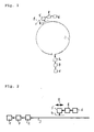
- Fig. 1 shows in a general form schematically a rotary transformer according to the invention.
- Fig. 2 shows in a general form schematically a device according to the invention for linear transmission.
- a particularly advantageous embodiment of a rotary transformer according to the invention is shown.
- the data of a data source (1) are transmitted via a coding device (7) and a transmitter (2) to a circularly arranged transmission conductor structure (3).
- the transmission conductor structure is arranged along the path of the movement, which is indicated by the directional arrow (9), and guides the signals fed by the transmitter.
- a receiving antenna (4) allows a tapping of the signals of the near field of the transmission line structure.
- the signals picked up by the antenna are conducted via a receiver (5) and a decoding device (8) to the data sink (6).
- Fig. 2 shows a device for linear transmission. Since the geometry of the transmission device or the path of the movement in principle has no influence on the embodiment of the invention, the reference numerals correspond to those of FIG. 1.
Landscapes
- Engineering & Computer Science (AREA)
- Computer Networks & Wireless Communication (AREA)
- Signal Processing (AREA)
- Power Engineering (AREA)
- Arrangements For Transmission Of Measured Signals (AREA)
- Optical Communication System (AREA)
- Detection And Prevention Of Errors In Transmission (AREA)
- Dc Digital Transmission (AREA)
- Near-Field Transmission Systems (AREA)
Abstract
Description
Die Erfindung bezieht sich auf Drehübertrager zur Übertragung digitaler Signale zwischen mehreren gegeneinander drehbar beweglichen Einheiten.The invention relates to rotary transformer for transmitting digital signals between a plurality of mutually rotatably movable units.
Der Übersichtlichkeit halber wird in diesem Dokument nicht zwischen der Übertragung zwischen gegeneinander beweglichen Einheiten und einer feststehenden und dazu beweglichen Einheiten unterschieden, da dies nur eine Frage des Ortsbezugs ist und keinen Einfluss auf die Funktionsweise der Erfindung hat. Ebenso wird nicht weiter zwischen der Übertragung von Signalen und Energie unterschieden, da die Wirkungsmechanismen hier die selben sind.For the sake of clarity, no distinction is made in this document between the transmission between mutually movable units and a stationary and movable unit, since this is only a question of location reference and has no influence on the operation of the invention. Likewise, no distinction is made between the transmission of signals and energy, since the mechanisms of action are the same here.
Bei drehbaren Einheiten wie Radaranlagen oder auch Computertomographen und auch bei linear beweglichen Einheiten wie Kran- und Förderanlagen ist es notwendig, zwischen gegeneinander beweglichen Einheiten elektrische Signale bzw. Energie zu übertragen. Hierzu ist meist eine Leiterstruktur in der ersten Einheit und ein entsprechender Abgriff in der zweiten Einheit vorgesehen. In den folgenden Ausführungen bezieht sich der Begriff Leiterstrukturen auf alle denkbaren Formen von Leiterstrukturen, welche geeignet sind, elektrische Signale zu führen. Dies bezieht sich auch auf die bekannten kontaktierenden Schleifbahnen bzw. Schleifringe. Wesentlich bei der Übertragung mittels Drehübertragern bzw. linearer " Schleifleitungen ", welche auch kontaktlos ausgeführt sein können, ist die geringe Distanz der Übertragung zwischen den gegeneinander beweglichen Einheiten. So kann das Signal wahlweise galvanisch oder im Nahfeld der Leiterstrukturen ausgekoppelt werden.With rotatable units such as radar systems or computer tomographs and also with linearly movable units such as crane and conveyor systems, it is necessary to transmit electrical signals or energy between mutually movable units. For this purpose, a conductor structure in the first unit and a corresponding tap in the second unit is usually provided. In the following embodiments, the term ladder structures refers to all conceivable forms of conductor structures which are suitable for carrying electrical signals. This also applies to the known contacting sliding tracks or slip rings. Essential in the transmission by means of rotary transducers or linear "sliding lines", which can also be designed contactless, is the small distance of the transmission between the mutually movable units. Thus, the signal can optionally be coupled out galvanically or in the near field of the conductor structures.
Eine entsprechende Vorrichtung ist in der deutschen Offenlegungsschrift DE 44 12 958 A1 beschrieben. Das zu übertragende Signal wird hier in eine Streifenleitung der ersten Einheit, welche längs des Weges der Bewegung der gegeneinander beweglichen Einheiten angeordnet ist, eingespeist. Mittels kapazitiver oder induktiver Kopplung wird das Signal von der zweiten Einheit abgegriffen.A corresponding device is described in the German patent application DE 44 12 958 A1. The signal to be transmitted is fed here into a strip line of the first unit, which is arranged along the path of movement of the mutually movable units. By means of capacitive or inductive coupling, the signal is tapped from the second unit.
Der Koppelfaktor des Signals zwischen den beiden Einheiten hängt im wesentlichen von dem Abstand der beiden Einheiten zueinander ab. Gerade bei räumlich ausgedehnten Übertragungssystemen und insbesondere bei hohen Bewegungsgeschwindigkeiten lassen sich auf Grund mechanischer Toleranzen die Abstände zwischen den beweglichen Einheiten nicht beliebig exakt festlegen. Diese können in der Praxis in einem Bereich von einer direkten Berührung bis einige Zentimeter Abstand, vorzugsweise zwischen, 0.01 mm und 10 mm variieren. Daher variiert der Koppelfaktor häufig mit der Position der beiden Einheiten zueinander, der Geschwindigkeit (z. B. durch Verursachung von Vibrationen) und anderen Einflussgrößen. Gleichzeitig ändert sich die Signalamplitude am Eingang des Empfängers. Dadurch ergeben sich bei herkömmlich aufgebauten Empfängern Veränderungen im Signal, welche sich beispielsweise als erhöhter Jitter oder sogar Bitfehler bemerkbar machen. Ebenso ergeben sich hierbei Änderungen der Störfestigkeit.The coupling factor of the signal between the two units depends essentially on the distance of the two units from each other. Especially with spatially extended transmission systems and in particular at high speeds of movement can not be determined arbitrarily exactly due to mechanical tolerances, the distances between the moving units. These may in practice vary in a range from a direct touch to a few centimeters distance, preferably between .01 mm and 10 mm. Therefore, the coupling factor often varies with the position of the two units to each other, the speed (eg, by causing vibrations), and other factors. At the same time, the signal amplitude at the input of the receiver changes. This results With conventionally designed receivers, changes in the signal, which manifest themselves as increased jitter or even bit errors, for example. Likewise, this results in changes in immunity to interference.
Eine Verbesserung der Übertragungseigenschaften bringt die in der DE 197 00 110 A1 veröffentlichte Vorrichtung, welche an Stelle einer Streifenleitung eine Leiterstruktur mit Filtereigenschaften aufweist. Grundsätzlich bleiben aber die Probleme bestehen.An improvement in the transmission properties brings the DE 197 00 110 A1 published device, which has a conductor structure with filter properties in place of a stripline. Basically, however, the problems persist.
Aus der US 6,433,631 B2 ist eine Vorrichtung zur Regelung des Eingangspegels am Empfänger offenbart. Hierzu wird die Signalamplitude nach einem Vorverstärker gemessenen und entsprechend dieser Signalamplitude ein vor dem Vorverstärker vorgesehenes Dämpfungsglied gesteuert. Der Nachteil dieser Anordnung ist, dass hierdurch ausschließlich dem Empfänger ein Signal mit konstanter Amplitude zur Verfügung gestellt werden kann.From US 6,433,631 B2 a device for controlling the input level at the receiver is disclosed. For this purpose, the signal amplitude is measured according to a preamplifier and, in accordance with this signal amplitude, an attenuator provided in front of the preamplifier is controlled. The disadvantage of this arrangement is that in this way only a constant amplitude signal can be made available to the receiver.
In der DE 196 44 503 A1 ist eine Drehkupplung offenbart, bei der der Frequenzgang des zu übertragenden Signals an die Übertragungseigenschaften der Koppeleinrichtung angepasst wird.DE 196 44 503 A1 discloses a rotary coupling in which the frequency response of the signal to be transmitted is adapted to the transmission characteristics of the coupling device.
Der Nachteil der dem Stand der Technik entsprechenden Vorrichtungen liegt in einer noch unzureichenden Störfestigkeit. So können zwar die Sendesignalpegel in der Leitung erhöht werden, um die Störfestigkeit zu verbessern. Damit steigt aber auch die unerwünschte Abstrahlung hochfrequenter Signale. Bei einer Verringerung des Sendesignalpegels sinkt zwar die Abstrahlung, aber die Immunität gegen eingestreute Störungen von außen sinkt ebenfalls.The disadvantage of the prior art devices is still insufficient immunity to interference. Thus, although the transmission signal levels can be increased in the line to improve immunity to interference. But this also increases the unwanted emission of high-frequency signals. When the transmission signal level is reduced, the radiation decreases, but the immunity to interspersed interference from the outside also decreases.
Es stellt sich die Aufgabe, eine Vorrichtung zur Drehübertragung elektrischer Signale zu gestalten, welche die oben aufgezeigten Nachteile vermeidet und insbesondere eine hohe Störfestigkeit und somit eine hohe Übertragungsqualität der Signale aufweist.It has as its object to design a device for the rotational transmission of electrical signals, which avoids the above-mentioned disadvantages and in particular has a high immunity to interference and thus a high transmission quality of the signals.
Die Aufgabe wird erfindungsgemäß mit den in den unabhängigen Ansprüchen angegebenen Mitteln gelöst. Vorteilhafte Weiterbildungen der Erfindung sind Gegenstand der abhängigen weiteren Ansprüche.The object is achieved according to the invention with the means specified in the independent claims. Advantageous developments of the invention are the subject of the dependent claims.
Eine erfindungsgemäße Vorrichtung dient zur Übertragung digitaler Signale zwischen wenigstens zwei gegeneinander drehbaren Einheiten, vorzugsweise als Drehübertrager, wie sie beispielsweise im Computertomografen einsetzbar sind. Selbstverständlich können auf jeder Seite der Bewegung eine oder mehrere Einheiten angeordnet sind. Zur vereinfachten Darstellung wird hier ausschließlich auf eine zweite Einheit, welche gegenüber einer ersten Einheit drehbar beweglich ist, Bezug genommen.
Der ersten Einheit ist eine Datenquelle (1) zur Erzeugung eines seriellen Datenstroms, wie beispielsweise ein dem Stand der Technik entsprechender Parallele/Seriell - Wandler zugeordnet. Weiterhin ist ein Sender (2) vorgesehen, der aus dem seriellen Datenstrom der Datenquelle elektrische Signale zu Übertragung über eine Sendeleiterstruktur (3) erzeugt. Der zweiten Einheit ist eine Empfangsantenne (4) zum Abgriff elektrische Signale im Nahfeld der Sendeleiterstruktur zugeordnet. Die elektrischen Signale der Empfangsantenne werden über einen Empfänger (5) einer Datensenke (6) zur Weiterverarbeitung der Signale zugeführt.A device according to the invention is used to transmit digital signals between at least two mutually rotatable units, preferably as a rotary transformer, as they are used for example in computer tomography. Of course, one or more units can be arranged on each side of the movement. For simplified illustration, reference is made here exclusively to a second unit, which is rotatable relative to a first unit.
The first unit is associated with a data source (1) for generating a serial data stream, such as a prior art parallel / serial converter. Furthermore, a transmitter (2) is provided, which generates electrical signals for transmission via a transmission conductor structure (3) from the serial data stream of the data source. The second unit is associated with a receiving antenna (4) for picking up electrical signals in the near field of the transmission line structure. The electrical signals of the receiving antenna are fed via a receiver (5) of a data sink (6) for further processing of the signals.
Erfindungsgemäß ist nun eine Kodiereinrichtung (7) zwischen Datenquelle (1) und Sender (2) vorgesehen. Diese Kodiereinrichtung ist derart ausgelegt, dass sie die digitale Kodierung des Datenstroms derart umsetzt, dass die Daten mit minimalen Fehlern über Sender (2), Sendeleiterstruktur (3), Empfangsantenne (4) sowie Empfänger (5) übertragbar sind.According to the invention, an encoding device (7) is now provided between the data source (1) and the transmitter (2). This coding device is designed such that it implements the digital coding of the data stream in such a way that the data can be transmitted with minimal errors via transmitter (2), transmitter conductor structure (3), receiver antenna (4) and receiver (5).
Entsprechend dem Wesen der Erfindung ist die Kodiereinrichtung in dem elektrischen Signalpfad zwischen Datenquelle (1) und Sender (2) vorgesehen. Selbstverständlich kann diese Kodiereinrichtung auch in dem Sender (2) angeordnet sein.According to the essence of the invention, the coding device is provided in the electrical signal path between the data source (1) and transmitter (2). Of course, this coding device can also be arranged in the transmitter (2).
Weiterhin ist der zweiten Einheit zwischen Empfänger (5) und Datensenke (6) eine Dekodiereinrichtung (9) zur Dekodierung der von der Kodiereinrichtung (7) kodierten Signale zugeordnet. Durch diese Dekodiereinrichtung wird die Kodierung der Kodiereinrichtung wieder rückgängig gemacht, so dass die der Datensenke zugeführten Signale dem Datenstrom der Datenquelle (1) entsprechen. Selbstverständlich kann die Dekodiereinrichtung auch im Empfänger (5) angeordnet sein. Somit ist die Kodierung zum optimalen Transport der Daten auf der Datenstrecke für Datenquelle bzw. Datensenke vollkommen transparent.Furthermore, the second unit between receiver (5) and data sink (6) is assigned a decoding device (9) for decoding the signals encoded by the coding device (7). By means of this decoding device, the coding of the coding device is reversed again, so that the signals supplied to the data sink correspond to the data stream of the data source (1). Of course, the decoder can also be arranged in the receiver (5). Thus, the coding for the optimal transport of data on the data path for data source or data sink is completely transparent.
Erfindungsgemäß erfolgt durch die Kodierung des Datenstroms mittels der Kodiereinrichtung (7) eine Umsetzung der spektralen Eigenschaften des Datenstroms. So erfolgt die Kodierung derart, dass die Leistung des Signals in vorgegebenen Spektralbereichen wahlweise erhöht oder abgesenkt wird. Durch eine Anpassung der spektralen Eigenschaften des Signals kann die Übertragungsqualität an den Frequenzgang der übrigen Übertragungsstrecke sowie an vorhandene Störer bzw. störempfindliche Komponenten angepasst werden.According to the invention, the coding of the data stream by means of the coding device (7) implements a conversion of the spectral properties of the data stream. This is done the coding such that the power of the signal in predetermined spectral ranges is selectively increased or decreased. By adapting the spectral properties of the signal, the transmission quality can be adapted to the frequency response of the remaining transmission path and to existing interferers or interference-sensitive components.
Weist die Datenstrecke zwischen Sender und Empfänger beispielsweise in einem oder mehreren bekannten Frequenzbereichen eine besonders hohe Dämpfung auf, so kann nun vorteilhafterweise die Kodierung derart ausgelegt werden, dass dieser Frequenzbereich zur Übertragung nicht verwendet wird. Im umgekehrten Fall kann bei Frequenzbereichen besonders niedriger Dämpfung durch geeignete Kodierung ein Maximum im diese Frequenzbereiche gelegt werden.If the data link between transmitter and receiver has a particularly high attenuation, for example in one or more known frequency ranges, the coding can now advantageously be designed such that this frequency range is not used for the transmission. In the reverse case, a maximum in these frequency ranges can be set at frequency ranges of particularly low attenuation by suitable coding.
Sind externe Störer vorhanden, welche die Übertragung der Signale beeinträchtigen, so wird die Kodierung vorteilhafterweise derart vorgenommen, dass wahlweise diese Frequenzbereiche ausgespart werden. Alternativ dazu könnte auch in diesen Frequenzbereichen eine besonders hohe Amplitude abgegeben werden.If external interferers are present which impair the transmission of the signals, the coding is advantageously carried out in such a way that optionally these frequency ranges are omitted. Alternatively, a particularly high amplitude could be emitted in these frequency ranges.
Sind besonders störempfindliche Komponenten außerhalb der Datenstrecke vorhanden, so kann durch die Kodierung das Spektrum des übertragenen Signals derart angepasst werden, dass in dem Frequenzbereichen hoher Störempfindlichkeit nur geringe Signalpegel abgegeben werden. Grundsätzlich kann hier auch das bekannte Linienspektrum digitaler Signale durch eine geeignete Kodierung verbreitert werden, um die nach den gängigen EMV-Normen gemessenen Grenzwerte einzuhalten.If particularly interference-sensitive components are present outside the data path, then the coding of the spectrum of the transmitted signal can be adjusted such that only low signal levels are emitted in the frequency ranges of high susceptibility to interference. Basically, here also the known line spectrum of digital signals by a suitable coding be widened to comply with the limits measured according to the common EMC standards.
Die Kodierung erfolgt vorteilhafterweise derart, dass das übertragene Signal gleichstromfrei ist.The coding is advantageously carried out in such a way that the transmitted signal is DC-free.
Weiterhin ist die Art der Kodierung dynamisch einstellbar, so dass diese sich vorteilhafter Weise an durch die Bewegung hervorgerufene Änderungen anpassen kann. Hierzu ist vorteilhafterweise eine Steuereinheit mit Mitteln zur Ermittlung des aktuellen Betriebszustandes und einer entsprechenden Vorgabe der Kodierung an die Kodiereinrichtung vorgesehen. So kann beispielsweise die Kodierung positionsabhängig vorgegeben werden. Ein Positionssensor könnte die relative Position der gegeneinander drehbaren Teile signalisieren und eine entsprechende Kodierung vorgeben. Ebenso kann eine zeitabhängige Kodierung vorgegeben werden. Dies ist insbesondere bei konstanter Drehgeschwindigkeit vorteilhaft, da hier wieder eine Zuordnung zur Position möglich ist.Furthermore, the type of coding is dynamically adjustable so that it can advantageously adapt to changes caused by the movement. For this purpose, a control unit is advantageously provided with means for determining the current operating state and a corresponding specification of the coding to the coding device. Thus, for example, the coding can be specified position-dependent. A position sensor could signal the relative position of the mutually rotatable parts and specify a corresponding coding. Likewise, a time-dependent coding can be specified. This is particularly advantageous at a constant rotational speed, as here again an assignment to the position is possible.
Alternativ sieht die Erfindung vor, dass die Kodierungsfunktion der Kodiereinrichtung zeitabhängig variiert wird, um die Einflüsse zeitabhängiger Störer zu kompensieren. So kann beispielsweise die Kodierung entsprechend der Störspitzen einer Stromversorgung, einer Röntgenröhre oder eines Elektromotors angepasst werden.Alternatively, the invention provides that the coding function of the coding device is varied in a time-dependent manner in order to compensate for the influences of time-dependent interferers. For example, the coding can be adjusted according to the interference peaks of a power supply, an X-ray tube or an electric motor.
Alternativ sieht die Erfindung vor, dass die Kodierungsfunktion der Kodiereinrichtung in Abhängigkeit von elektrischen Messgrößen angepasst wird. So kann beispielsweise eine Messgröße entsprechend einem Störpegel der Übertragungseinrichtung ermittelt werden. Diese Messgröße kann nun wahlweise analog zur Anpassung bestimmter spektraler Anteile derart herangezogen werden, dass die in den gestörten Frequenzbereichen übertragenen spektraler in Anteile des Nutzsignals in ihrer Amplitude angehoben werden. Ebenso kann diese Messgröße zu Signalisierung einer Verschiebung der spektralen Anteile des Nutzsignals in ungestörte Bereiche herangezogen werden. Weiterhin kann auch die Messgröße zur Auslösung einer Umschaltung einer anderen spektralen Amplitudeverteilung des Nutzsignals herangezogen werden.Alternatively, the invention provides that the coding function of the coding device in Depending on electrical parameters is adjusted. Thus, for example, a measured variable corresponding to a noise level of the transmission device can be determined. This measured variable can now optionally be used analogously to the adaptation of certain spectral components in such a way that the spectral components of the useful signal transmitted in the disturbed frequency ranges are raised in their amplitude. Likewise, this parameter can be used to signal a shift of the spectral components of the useful signal in undisturbed areas. Furthermore, the measured variable can be used to trigger a changeover of another spectral amplitude distribution of the useful signal.
Erfindungsgemäß kann eine dynamische Anpassung zu Beginn einer Übertragung erfolgen, wobei während der Übertragungsdauer die zu Beginn vorgenommenen Anpassungen bzw. Einstellungen beibehalten werden. Ebenso ist aber auch eine dynamische Anpassung während der gesamten Übertragungsdauer möglich.According to the invention, a dynamic adaptation can take place at the beginning of a transmission, wherein during the transmission period the adjustments or adjustments made at the beginning are retained. Likewise, however, a dynamic adaptation during the entire transmission period is possible.
In einer Ausgestaltung der Erfindung ist die Kodiereinrichtung derart gestaltet, dass sie zusätzliche Redundanz in dem Datenstrom einbringt. Durch diese zusätzliche Redundanz werden weitergehende Korrekturen der Informationen des Datenstroms im Falle von Übertragungsfehlern ermöglicht. Diese Korrekturen können nun wahlweise von der Datensenke, bevorzugt aber von einer Dekodiereinrichtung vorgenommen werden.In one embodiment of the invention, the coding device is designed such that it introduces additional redundancy in the data stream. This additional redundancy allows further corrections to the information of the data stream in case of transmission errors. These corrections can now be made optionally by the data sink, but preferably by a decoding device.
In einer anderen Ausgestaltung der Erfindung ist die Kodiereinrichtung derart ausgelegt, dass sie die Datenrate des seriellen Datenstroms erhöht und somit Raum für zusätzliche redundante Informationen schafft. Vorteilhafterweise erfolgt eine solche Umsetzung der Datenrate oder auch wahlweise eine zuvor beschriebene Umsetzung der Kodierung bzw. der Paket Informationen durch Umsetzung des seriellen Datenstroms der Datenquellen in parallele Datenworte, welche leicht modifiziert werden können, sowie die anschließende Umsetzung in einen geänderten seriellen Datenstrom zur Übertragung.In another embodiment of the invention, the coding device is designed such that it increases the data rate of the serial data stream and thus creates space for additional redundant information. Advantageously, such a conversion of the data rate or alternatively a previously described implementation of the coding or the packet information by conversion of the serial data stream of the data sources in parallel data words, which can be easily modified, and the subsequent conversion into a modified serial data stream for transmission.
Eine weitere erfindungsgemäße Vorrichtung weist eine Kodiereinrichtung auf, welche zur Erhöhung der Sicherheit die zu übertragenden Signale kodiert bzw. verschlüsselt. Entsprechend der Sicherheitsanforderungen kann hierzu ein kürzerer oder längerer Schlüssel verwendet werden. Entsprechend den Mittel zur Entschlüsselung können kann wahlweise in der Datensenke bzw. in der Dekodiereinrichtung vorgesehen sein.A further device according to the invention has an encoding device which encodes or encrypts the signals to be transmitted in order to increase security. Depending on the security requirements, a shorter or longer key may be used. According to the means for decryption can be provided either in the data sink or in the decoder.
Eine andere Ausgestaltung der Erfindung sieht vor, dass wahlweise in der Kodiereinrichtung (7) beziehungsweise in der Dekodiereinrichtung (8) Mittel zur Taktregeneration vorgesehen sind. Weiterhin können an beliebiger Stelle der Datenstrecke Mittel zur Taktregeneration vorgesehen sein. Durch die Taktregeneration eines Signals erfolgt die Synchronisation des Signals auf einen Takt konstanter Frequenz, welcher meist mit Hilfe einer PLL aus dem Datenstrom gewonnen wird. Dadurch kann die Kurvenformen des Signals wesentlich verbessert werden. So hat das regenerierte Signal wieder klare Flanken mit reduziertem Jitter und folglich einer vergrößerten Augenöffnung.Another embodiment of the invention provides that means for clock regeneration are optionally provided in the coding device (7) or in the decoding device (8). Furthermore, means for clock regeneration may be provided at any point of the data path. Due to the clock regeneration of a signal, the synchronization of the signal to a clock of constant frequency, which is usually obtained by means of a PLL from the data stream. This can significantly improve the waveforms of the signal become. Thus, the regenerated signal again has clear edges with reduced jitter and consequently an enlarged eye opening.
In einer anderen Ausgestaltung der Erfindung ist wenigstens ein Filter wahlweise dem Sender (2) beziehungsweise dem Empfänger (5) zugeordnet. Dieses Filter dient zur Anpassung an die Übertragungseigenschaften der Datenstrecke zwischen Sender und Empfänger. So lassen sich insbesondere auf Seiten des Empfängers frequenzabhängige Amplituden- und Phasengänge korrigieren. Durch derartige Filter können auch externe Störungen reduziert werden.In another embodiment of the invention, at least one filter is optionally associated with the transmitter (2) or the receiver (5). This filter is used to adapt to the transmission characteristics of the data link between sender and receiver. This makes it possible to correct frequency-dependent amplitude and phase responses, in particular on the receiver side. Such filters can also reduce external interference.
Eine andere vorteilhafte Ausgestaltung des Erfindung besteht darin, dass das Filter dynamisch einstellbar ist. Gerade bei beweglichen Einheiten ändert sich die Übertragungscharakteristik dynamisch während der Bewegung. Diese kann durch dynamische Filtereinstellung kompensiert werden. Ein solches Filter kann beispielsweise durch einen Mikrocontroller oder durch eine einfache Regelschaltung gesteuert werden.Another advantageous embodiment of the invention is that the filter is dynamically adjustable. Especially with moving units, the transmission characteristic changes dynamically during the movement. This can be compensated by dynamic filter adjustment. Such a filter can be controlled for example by a microcontroller or by a simple control circuit.
In einer weiteren vorteilhaften Ausgestaltung ist die Vorrichtung selbstlernend bzw. adaptiv ausgelegt. Dies bedeutet, dass sie sich dynamisch, insbesondere während der Bewegung, an die Betriebszustände anpasst. Dies erfolgt durch Ermittlung bestimmter Betriebsparameter, wie Bitfehlerrate, Signalamplitude etc. und anschließende Einstellung von Kodiereinrichtung bzw. Dekodiereinrichtung bzw. den Filtern. Besonders günstig ist deshalb, hier einen Fuzzy-Controller einzusetzen. So kann beispielsweise die Redundanz bzw. die Datenrate als Funktion der Übertragungsfehler eingestellt werden. Dies bedeutet, dass bei einer hohen Anzahl von Übertragungsfehlern beispielsweise eine höhere Redundanz vorgesehen wird. Gerade bei Drehbewegungen, insbesondere mit konstanter Geschwindigkeit, ist es vorteilhaft, die Übertragungsfunktion über die Umdrehung zu speichern und entsprechend abhängig von der Zeit bzw. der Position die Einstellung von Kodiereinrichtung bzw. Dekodiereinrichtung bzw. Filtern vorzunehmen. Dies ist selbstverständlich auch bei linearen Bewegungen möglich, sofern eine Information über die Position vorhanden ist.In a further advantageous embodiment, the device is designed self-learning or adaptive. This means that it adapts dynamically, especially during the movement, to the operating conditions. This is done by determining certain operating parameters, such as bit error rate, signal amplitude, etc. and subsequent adjustment of encoder or decoder or the filters. Therefore, it is particularly favorable, here a fuzzy controller use. For example, the redundancy or the data rate can be set as a function of the transmission errors. This means that with a high number of transmission errors, for example, a higher redundancy is provided. Especially in the case of rotational movements, in particular with constant speed, it is advantageous to store the transfer function over the revolution and to make the adjustment of the coding device or decoding device or filters accordingly depending on the time or the position. This is of course also possible with linear movements, provided that information about the position is available.
Ein entsprechendes erfindungsgemäßes Verfahren zur breitbandigen Übertragung digitaler Signale sieht vor, dass die Signale derart kodiert werden, dass die spektrale Leistungsdichte der Signale in vorgegebenen spektralen Bereichen wahlweise erhöht oder abgesenkt wird.A corresponding method according to the invention for broadband transmission of digital signals provides that the signals are coded in such a way that the spectral power density of the signals in predetermined spectral ranges is optionally increased or decreased.
Die Erfindung wird nachstehend ohne Beschränkung des allgemeinen Erfindungsgedankens anhand von Ausführungsbeispielen unter Bezugnahme auf die Zeichnungen exemplarisch beschrieben.The invention will now be described by way of example without limitation of the general inventive idea by means of embodiments with reference to the drawings.
Fig. 1 zeigt in allgemeiner Form schematisch einen erfindungsgemäßen Drehübertrager.Fig. 1 shows in a general form schematically a rotary transformer according to the invention.
Fig. 2 zeigt in allgemeiner Form schematisch eine erfindungsgemäße Vorrichtung zur linearen Übertragung.Fig. 2 shows in a general form schematically a device according to the invention for linear transmission.
In der Fig. 1 ist eine besonders vorteilhafte Ausführungsform eines erfindungsgemäßen Drehübertragers abgebildet. Die Daten einer Datenquelle (1) werden über eine Kodiereinrichtung (7) und einen Sender (2) an eine kreisförmig angeordnete Sendeleiterstruktur (3) übertragen. Die Sendeleiterstruktur ist entlang der Bahn der Bewegung, die durch den Richtungspfeil (9) angedeutet ist, angeordnet und führt die durch den Sender eingespeisten Signale. Eine Empfangsantenne (4) ermöglicht einen Abgriff der Signale des Nahfeldes der Sendeleiterstruktur. Die von der Antenne abgegriffenen Signale werden über einen Empfänger (5) und eine Dekodiereinrichtung (8) zur Datensenke (6) geleitet.In Fig. 1, a particularly advantageous embodiment of a rotary transformer according to the invention is shown. The data of a data source (1) are transmitted via a coding device (7) and a transmitter (2) to a circularly arranged transmission conductor structure (3). The transmission conductor structure is arranged along the path of the movement, which is indicated by the directional arrow (9), and guides the signals fed by the transmitter. A receiving antenna (4) allows a tapping of the signals of the near field of the transmission line structure. The signals picked up by the antenna are conducted via a receiver (5) and a decoding device (8) to the data sink (6).
Fig. 2 zeigt eine Vorrichtung zur linearen Übertragung. Da die Geometrie der Übertragungseinrichtung bzw. die Bahn der Bewegung grundsätzlich keinen Einfluß auf die Ausgestaltung der Erfindung hat, entsprechen die Bezugszeichen denen aus Fig. 1.Fig. 2 shows a device for linear transmission. Since the geometry of the transmission device or the path of the movement in principle has no influence on the embodiment of the invention, the reference numerals correspond to those of FIG. 1.
- 11
- DatenquelleData Source
- 22
- Sendertransmitter
- 33
- SendeleiterstrukturTransmission conductor structure
- 44
- Empfangsantennereceiving antenna
- 55
- Empfängerreceiver
- 66
- Datensenkedata sink
- 77
- Kodiereinrichtungcoding
- 88th
- Dekodiereinrichtungdecoding
- 99
- Richtungspfeil für BewegungsrichtungDirectional arrow for direction of movement
Claims (9)
- Rotating data transmission device for electrical transmission of broadband digital signals between at least one first unit and at least one second unit disposed to be rotatable relative to the first unit, comprising in association with the first unit:- a data source (1) for generating a serial data stream;- a transmitter (2) for generating electrical signals from the serial data stream of the data source;- a transmission conductor structure (3) for carrying the electrical signals generated by the transmitter;and in association with the second unit:- a receiving antenna (4) for tapping-off electrical signals in a near field of the transmission conductor structure;- a receiver (5) for receiving the signals tapped-off by the receiving antenna;- a data sink (6) for further processing the signals received by the receiver;characterized in that
an encoder (7) is provided between the data source (1) and the transmitter (2) for converting a digital coding of the data stream so that the power in given spectral ranges is optionally increased or lowered; and that furthermore a decoder (8) is provided between the receiver (5) and the data sink (6) for restoring, from the data encoded by the encoder (7), the data in an original form as issued by the data sources (1); and that the encoding function of the encoder is adapted to be set dynamically as a function of a location of the rotary movement of the two units relative to each other, and/or as a function of time, and/or as a function of an electrical measurement parameter signalizing electrical levels, in particular interference levels, in the transmission conductor structure (3), the receiver antenna (4), and/or the receiver (5). - Device according to claim 1,
characterized in that
the encoder (7) is adapted to introduce additional redundancy into the data stream. - Device according to any one of the preceding claims,
characterized in that
the encoder (7) is adapted to increase or decrease the data rate of the serial data stream. - Device according to any one of the preceding claims,
characterized in that
the encoder (7) comprises means for enciphering the serial data stream of the data source (1). - Device according to any one of the preceding claims,
characterized in that
optionally the encoder (7) or the decoder (8) comprises means for timing recovery. - Device according to any one of the preceding claims,
characterized in that
at least one filter, optionally assigned to the transmitter (2) or the receiver (5), is provided for matching to the transmission characteristics of the data path between the transmitter and the receiver. - Device according to claim 6,
characterized in that
the filter is adapted to be set dynamically. - Device according to any one of the preceding claims,
characterized in that
the device is self-learning and dynamically adapts to the prevailing operating states by determining certain operating parameters such as the bit error rate, the signal amplitude etc. and subsequently setting the encoder or decoder, and/or the filters. - Method for broadband transmission of digital signals between at least one first unit and at least one second unit disposed to be rotatable relative to the first unit, comprising the following steps:- generating a serial data stream with a data source (1) assigned to the first unit;- encoding the data stream so that the spectral power density of the signals in given spectral regions is optionally increased or lowered dynamically as a function of the location of the rotary movement of the two units relative to each other, and/or as a function of time, and/or as a function of an electrical measurement parameter that signals electrical levels, in particular interference levels, to a transmission conductor structure (3), a receiving antenna (4), and/or a receiver (5);- generating electrical signals from the serial data stream of the data source with a transmitter (2);- conducting the electrical signals generated by the transmitter through the transmission conductor structure (3);- tapping-off electrical signals in a near field of the transmission conductor structure with a receiving antenna (4) assigned to the second unit;- receiving the signals tapped-off by the receiving antenna with a receiver (5);- decoding the signals with a decoder (9); and- further processing the signals of the receiver by a data sink.
Applications Claiming Priority (3)
| Application Number | Priority Date | Filing Date | Title |
|---|---|---|---|
| DE10245449 | 2002-09-27 | ||
| DE10245449A DE10245449A1 (en) | 2002-09-27 | 2002-09-27 | Device for the transmission of digital signals between moving units with influence on the spectral properties |
| PCT/EP2003/010463 WO2004032364A1 (en) | 2002-09-27 | 2003-09-19 | Device for transmitting digital signals between mobile units with an adaptation of the spectral characteristics |
Publications (2)
| Publication Number | Publication Date |
|---|---|
| EP1547271A1 EP1547271A1 (en) | 2005-06-29 |
| EP1547271B1 true EP1547271B1 (en) | 2006-11-29 |
Family
ID=31984238
Family Applications (1)
| Application Number | Title | Priority Date | Filing Date |
|---|---|---|---|
| EP03757874A Expired - Lifetime EP1547271B1 (en) | 2002-09-27 | 2003-09-19 | DEVICE and method FOR TRANSMITTING DIGITAL SIGNALS BETWEEN MOBILE UNITS WITH AN ADAPTATION OF THE SPECTRAL CHARACTERISTICS |
Country Status (6)
| Country | Link |
|---|---|
| US (1) | US7599445B2 (en) |
| EP (1) | EP1547271B1 (en) |
| AT (1) | ATE347194T1 (en) |
| AU (1) | AU2003273909A1 (en) |
| DE (2) | DE10245449A1 (en) |
| WO (1) | WO2004032364A1 (en) |
Families Citing this family (4)
| Publication number | Priority date | Publication date | Assignee | Title |
|---|---|---|---|---|
| DE102006054128A1 (en) * | 2006-04-24 | 2007-10-25 | Schleifring Und Apparatebau Gmbh | Optical rotary transmitter for e.g. computer tomograph scanner, has controller controlling data source and/or transmitter unit during error in reception of signals at receiver and/or during unlatching of phase locked loop |
| DE102006044660B3 (en) * | 2006-09-21 | 2008-04-30 | Siemens Ag | Method and device for transmitting a large number of parallel data between relatively moving units |
| US8295431B2 (en) * | 2007-06-21 | 2012-10-23 | Non-Contacting Rotary Joint | Non-contacting rotary joint |
| DE112020002615T5 (en) * | 2019-05-28 | 2022-04-28 | Moog Inc. | NON-CONTACT SLIP RING TRANSMITTER WITH GRADUATED FREQUENCY RESPONSE |
Family Cites Families (8)
| Publication number | Priority date | Publication date | Assignee | Title |
|---|---|---|---|---|
| US5400322A (en) * | 1993-08-20 | 1995-03-21 | Amati Communications Corp. | Updating of bit allocations in a multicarrier modulation transmission system |
| US5949796A (en) * | 1996-06-19 | 1999-09-07 | Kumar; Derek D. | In-band on-channel digital broadcasting method and system |
| DE19644503A1 (en) * | 1996-10-25 | 1998-05-07 | Schleifring & Apparatebau Gmbh | Electric signal transmitter with signal source |
| US5828719A (en) * | 1996-12-23 | 1998-10-27 | General Electric Company | Methods and apparatus for modulating data acquisition system gain |
| EP1051816B1 (en) * | 1997-12-31 | 2002-05-29 | Schleifring und Apparatebau GmbH | Device for transmitting signals with low-interference |
| US6299280B1 (en) * | 1998-05-18 | 2001-10-09 | Canon Research Centre France S.A. | Method of transmitting information by capacitive connection and a device adapted to implement it, such as a printer |
| US6301324B1 (en) * | 1999-03-31 | 2001-10-09 | General Electric Company | RF slipring receiver for a computerized tomography system |
| US20030099286A1 (en) * | 2001-07-31 | 2003-05-29 | Graziano Michael J. | Method and system for shaping transmitted power spectral density according to line conditions |
-
2002
- 2002-09-27 DE DE10245449A patent/DE10245449A1/en not_active Withdrawn
-
2003
- 2003-09-19 AT AT03757874T patent/ATE347194T1/en not_active IP Right Cessation
- 2003-09-19 DE DE50305869T patent/DE50305869D1/en not_active Expired - Lifetime
- 2003-09-19 AU AU2003273909A patent/AU2003273909A1/en not_active Abandoned
- 2003-09-19 EP EP03757874A patent/EP1547271B1/en not_active Expired - Lifetime
- 2003-09-19 WO PCT/EP2003/010463 patent/WO2004032364A1/en active IP Right Grant
-
2005
- 2005-03-25 US US11/090,700 patent/US7599445B2/en active Active
Also Published As
| Publication number | Publication date |
|---|---|
| DE10245449A1 (en) | 2004-04-08 |
| US20050231836A1 (en) | 2005-10-20 |
| ATE347194T1 (en) | 2006-12-15 |
| EP1547271A1 (en) | 2005-06-29 |
| WO2004032364A1 (en) | 2004-04-15 |
| US7599445B2 (en) | 2009-10-06 |
| DE50305869D1 (en) | 2007-01-11 |
| AU2003273909A1 (en) | 2004-04-23 |
Similar Documents
| Publication | Publication Date | Title |
|---|---|---|
| EP2160134B1 (en) | Contactless rotary transmitter | |
| EP1867073B1 (en) | Multi-channel data transfer system for computer tomographs | |
| DE102005026158B4 (en) | Data transmission system for computer tomographs | |
| DE2544693B2 (en) | Digital data transmission system exhibiting improved insensitivity to frequency-selective attenuation | |
| EP1729646A1 (en) | Rotary transmitter comprising a dielectric waveguide | |
| EP1051816A1 (en) | Device for transmitting signals with low-interference | |
| DE10245589B4 (en) | Device for transmitting digital signals between mobile units | |
| EP1547271B1 (en) | DEVICE and method FOR TRANSMITTING DIGITAL SIGNALS BETWEEN MOBILE UNITS WITH AN ADAPTATION OF THE SPECTRAL CHARACTERISTICS | |
| WO2003028325A2 (en) | Interlacing for signal transmission | |
| DE10245450B4 (en) | Apparatus and method for transmitting digital signals between variable rate mobile units | |
| EP1285476B1 (en) | Device for the broadband electrical signal and/or energy transmission with directional couplers | |
| DE10319248B4 (en) | Slip ring with lossy trace | |
| DE10262243B4 (en) | Signal transmission system for connecting two movable modules has data coding circuit on sender side producing given frequency spectrum of digital data according to transmission conditions | |
| DE10262316B3 (en) | Device for the transmission of digital signals between mobile units | |
| DE10245505B4 (en) | Device for transmitting digital signals between mobile units with analog filtering | |
| DE102006054128A1 (en) | Optical rotary transmitter for e.g. computer tomograph scanner, has controller controlling data source and/or transmitter unit during error in reception of signals at receiver and/or during unlatching of phase locked loop | |
| WO1997019483A2 (en) | Device for transmitting signals between moving parts | |
| DE10241583A1 (en) | Receiver for digital signals the are communication between units with relative motion such as rotary unit of radar or computer tomography scanners | |
| DE10260940B3 (en) | Device and method for broadband transmission of digital optical signals between movable units | |
| EP0920763B1 (en) | Data transmission by impulse position modulation and amplitude modulation | |
| EP3029829A1 (en) | Method for joint transmission of control signals and digital data signals | |
| DE10241581B4 (en) | Slip ring arrangement in particular for use in computer tomographs with control of the transmitter amplitude | |
| DE10215809A1 (en) | Sliding contact provides an electrical connection between a fixed and moving part and is in the form of a multi layer leaf spring | |
| DE102008000487A1 (en) | Rotary transformer with active compensation of the transfer function | |
| DE10241554A1 (en) | Digital signal receiver for signal transmission between relatively movable components, e.g. of crane, radar device or computer tomograph, with adjustment of digitizer dependent on measured signal quality |
Legal Events
| Date | Code | Title | Description |
|---|---|---|---|
| PUAI | Public reference made under article 153(3) epc to a published international application that has entered the european phase |
Free format text: ORIGINAL CODE: 0009012 |
|
| 17P | Request for examination filed |
Effective date: 20050427 |
|
| AK | Designated contracting states |
Kind code of ref document: A1 Designated state(s): AT BE BG CH CY CZ DE DK EE ES FI FR GB GR HU IE IT LI LU MC NL PT RO SE SI SK TR |
|
| AX | Request for extension of the european patent |
Extension state: AL LT LV MK |
|
| DAX | Request for extension of the european patent (deleted) | ||
| GRAP | Despatch of communication of intention to grant a patent |
Free format text: ORIGINAL CODE: EPIDOSNIGR1 |
|
| RTI1 | Title (correction) |
Free format text: DEVICE AND METHOD FOR TRANSMITTING DIGITAL SIGNALS BETWEEN MOBILE UNITS WITH AN ADAPTATION OF THE SPECTRAL CHARACTERISTICS |
|
| GRAS | Grant fee paid |
Free format text: ORIGINAL CODE: EPIDOSNIGR3 |
|
| GRAA | (expected) grant |
Free format text: ORIGINAL CODE: 0009210 |
|
| AK | Designated contracting states |
Kind code of ref document: B1 Designated state(s): AT BE BG CH CY CZ DE DK EE ES FI FR GB GR HU IE IT LI LU MC NL PT RO SE SI SK TR |
|
| PG25 | Lapsed in a contracting state [announced via postgrant information from national office to epo] |
Ref country code: NL Free format text: LAPSE BECAUSE OF FAILURE TO SUBMIT A TRANSLATION OF THE DESCRIPTION OR TO PAY THE FEE WITHIN THE PRESCRIBED TIME-LIMIT Effective date: 20061129 Ref country code: IT Free format text: LAPSE BECAUSE OF FAILURE TO SUBMIT A TRANSLATION OF THE DESCRIPTION OR TO PAY THE FEE WITHIN THE PRESCRIBED TIME-LIMIT;WARNING: LAPSES OF ITALIAN PATENTS WITH EFFECTIVE DATE BEFORE 2007 MAY HAVE OCCURRED AT ANY TIME BEFORE 2007. THE CORRECT EFFECTIVE DATE MAY BE DIFFERENT FROM THE ONE RECORDED. Effective date: 20061129 Ref country code: SK Free format text: LAPSE BECAUSE OF FAILURE TO SUBMIT A TRANSLATION OF THE DESCRIPTION OR TO PAY THE FEE WITHIN THE PRESCRIBED TIME-LIMIT Effective date: 20061129 Ref country code: SI Free format text: LAPSE BECAUSE OF FAILURE TO SUBMIT A TRANSLATION OF THE DESCRIPTION OR TO PAY THE FEE WITHIN THE PRESCRIBED TIME-LIMIT Effective date: 20061129 Ref country code: FI Free format text: LAPSE BECAUSE OF FAILURE TO SUBMIT A TRANSLATION OF THE DESCRIPTION OR TO PAY THE FEE WITHIN THE PRESCRIBED TIME-LIMIT Effective date: 20061129 Ref country code: CZ Free format text: LAPSE BECAUSE OF FAILURE TO SUBMIT A TRANSLATION OF THE DESCRIPTION OR TO PAY THE FEE WITHIN THE PRESCRIBED TIME-LIMIT Effective date: 20061129 Ref country code: IE Free format text: LAPSE BECAUSE OF FAILURE TO SUBMIT A TRANSLATION OF THE DESCRIPTION OR TO PAY THE FEE WITHIN THE PRESCRIBED TIME-LIMIT Effective date: 20061129 Ref country code: RO Free format text: LAPSE BECAUSE OF FAILURE TO SUBMIT A TRANSLATION OF THE DESCRIPTION OR TO PAY THE FEE WITHIN THE PRESCRIBED TIME-LIMIT Effective date: 20061129 |
|
| REG | Reference to a national code |
Ref country code: GB Ref legal event code: FG4D Free format text: NOT ENGLISH |
|
| REG | Reference to a national code |
Ref country code: CH Ref legal event code: EP |
|
| REG | Reference to a national code |
Ref country code: IE Ref legal event code: FG4D Free format text: LANGUAGE OF EP DOCUMENT: GERMAN |
|
| REF | Corresponds to: |
Ref document number: 50305869 Country of ref document: DE Date of ref document: 20070111 Kind code of ref document: P |
|
| PG25 | Lapsed in a contracting state [announced via postgrant information from national office to epo] |
Ref country code: SE Free format text: LAPSE BECAUSE OF FAILURE TO SUBMIT A TRANSLATION OF THE DESCRIPTION OR TO PAY THE FEE WITHIN THE PRESCRIBED TIME-LIMIT Effective date: 20070228 Ref country code: DK Free format text: LAPSE BECAUSE OF FAILURE TO SUBMIT A TRANSLATION OF THE DESCRIPTION OR TO PAY THE FEE WITHIN THE PRESCRIBED TIME-LIMIT Effective date: 20070228 Ref country code: BG Free format text: LAPSE BECAUSE OF FAILURE TO SUBMIT A TRANSLATION OF THE DESCRIPTION OR TO PAY THE FEE WITHIN THE PRESCRIBED TIME-LIMIT Effective date: 20070228 |
|
| PG25 | Lapsed in a contracting state [announced via postgrant information from national office to epo] |
Ref country code: ES Free format text: LAPSE BECAUSE OF FAILURE TO SUBMIT A TRANSLATION OF THE DESCRIPTION OR TO PAY THE FEE WITHIN THE PRESCRIBED TIME-LIMIT Effective date: 20070312 |
|
| GBT | Gb: translation of ep patent filed (gb section 77(6)(a)/1977) |
Effective date: 20070222 |
|
| PG25 | Lapsed in a contracting state [announced via postgrant information from national office to epo] |
Ref country code: PT Free format text: LAPSE BECAUSE OF FAILURE TO SUBMIT A TRANSLATION OF THE DESCRIPTION OR TO PAY THE FEE WITHIN THE PRESCRIBED TIME-LIMIT Effective date: 20070430 |
|
| NLV1 | Nl: lapsed or annulled due to failure to fulfill the requirements of art. 29p and 29m of the patents act | ||
| REG | Reference to a national code |
Ref country code: IE Ref legal event code: FD4D |
|
| ET | Fr: translation filed | ||
| PLBE | No opposition filed within time limit |
Free format text: ORIGINAL CODE: 0009261 |
|
| STAA | Information on the status of an ep patent application or granted ep patent |
Free format text: STATUS: NO OPPOSITION FILED WITHIN TIME LIMIT |
|
| 26N | No opposition filed |
Effective date: 20070830 |
|
| BERE | Be: lapsed |
Owner name: SCHLEIFRING UND APPARATEBAU G.M.B.H. Effective date: 20070930 |
|
| PG25 | Lapsed in a contracting state [announced via postgrant information from national office to epo] |
Ref country code: GR Free format text: LAPSE BECAUSE OF FAILURE TO SUBMIT A TRANSLATION OF THE DESCRIPTION OR TO PAY THE FEE WITHIN THE PRESCRIBED TIME-LIMIT Effective date: 20070301 Ref country code: MC Free format text: LAPSE BECAUSE OF NON-PAYMENT OF DUE FEES Effective date: 20070930 |
|
| REG | Reference to a national code |
Ref country code: CH Ref legal event code: PL |
|
| PG25 | Lapsed in a contracting state [announced via postgrant information from national office to epo] |
Ref country code: CH Free format text: LAPSE BECAUSE OF NON-PAYMENT OF DUE FEES Effective date: 20070930 Ref country code: LI Free format text: LAPSE BECAUSE OF NON-PAYMENT OF DUE FEES Effective date: 20070930 |
|
| PG25 | Lapsed in a contracting state [announced via postgrant information from national office to epo] |
Ref country code: BE Free format text: LAPSE BECAUSE OF NON-PAYMENT OF DUE FEES Effective date: 20070930 |
|
| PG25 | Lapsed in a contracting state [announced via postgrant information from national office to epo] |
Ref country code: AT Free format text: LAPSE BECAUSE OF NON-PAYMENT OF DUE FEES Effective date: 20070919 |
|
| PG25 | Lapsed in a contracting state [announced via postgrant information from national office to epo] |
Ref country code: EE Free format text: LAPSE BECAUSE OF FAILURE TO SUBMIT A TRANSLATION OF THE DESCRIPTION OR TO PAY THE FEE WITHIN THE PRESCRIBED TIME-LIMIT Effective date: 20061129 |
|
| PG25 | Lapsed in a contracting state [announced via postgrant information from national office to epo] |
Ref country code: LU Free format text: LAPSE BECAUSE OF NON-PAYMENT OF DUE FEES Effective date: 20070919 Ref country code: CY Free format text: LAPSE BECAUSE OF FAILURE TO SUBMIT A TRANSLATION OF THE DESCRIPTION OR TO PAY THE FEE WITHIN THE PRESCRIBED TIME-LIMIT Effective date: 20061129 |
|
| PG25 | Lapsed in a contracting state [announced via postgrant information from national office to epo] |
Ref country code: TR Free format text: LAPSE BECAUSE OF FAILURE TO SUBMIT A TRANSLATION OF THE DESCRIPTION OR TO PAY THE FEE WITHIN THE PRESCRIBED TIME-LIMIT Effective date: 20061129 Ref country code: HU Free format text: LAPSE BECAUSE OF FAILURE TO SUBMIT A TRANSLATION OF THE DESCRIPTION OR TO PAY THE FEE WITHIN THE PRESCRIBED TIME-LIMIT Effective date: 20070530 |
|
| PGFP | Annual fee paid to national office [announced via postgrant information from national office to epo] |
Ref country code: GB Payment date: 20140923 Year of fee payment: 12 |
|
| PGFP | Annual fee paid to national office [announced via postgrant information from national office to epo] |
Ref country code: FR Payment date: 20140917 Year of fee payment: 12 |
|
| GBPC | Gb: european patent ceased through non-payment of renewal fee |
Effective date: 20150919 |
|
| REG | Reference to a national code |
Ref country code: FR Ref legal event code: ST Effective date: 20160531 |
|
| PG25 | Lapsed in a contracting state [announced via postgrant information from national office to epo] |
Ref country code: GB Free format text: LAPSE BECAUSE OF NON-PAYMENT OF DUE FEES Effective date: 20150919 |
|
| PG25 | Lapsed in a contracting state [announced via postgrant information from national office to epo] |
Ref country code: FR Free format text: LAPSE BECAUSE OF NON-PAYMENT OF DUE FEES Effective date: 20150930 |
|
| PGFP | Annual fee paid to national office [announced via postgrant information from national office to epo] |
Ref country code: DE Payment date: 20220630 Year of fee payment: 20 |
|
| REG | Reference to a national code |
Ref country code: DE Ref legal event code: R071 Ref document number: 50305869 Country of ref document: DE |