EP1545278B1 - Machine for producing a beverage by hot water infusion - Google Patents
Machine for producing a beverage by hot water infusion Download PDFInfo
- Publication number
- EP1545278B1 EP1545278B1 EP03780267A EP03780267A EP1545278B1 EP 1545278 B1 EP1545278 B1 EP 1545278B1 EP 03780267 A EP03780267 A EP 03780267A EP 03780267 A EP03780267 A EP 03780267A EP 1545278 B1 EP1545278 B1 EP 1545278B1
- Authority
- EP
- European Patent Office
- Prior art keywords
- hot water
- circuit
- valve
- hydraulic
- water distribution
- Prior art date
- Legal status (The legal status is an assumption and is not a legal conclusion. Google has not performed a legal analysis and makes no representation as to the accuracy of the status listed.)
- Expired - Lifetime
Links
Images


Classifications
-
- A—HUMAN NECESSITIES
- A47—FURNITURE; DOMESTIC ARTICLES OR APPLIANCES; COFFEE MILLS; SPICE MILLS; SUCTION CLEANERS IN GENERAL
- A47J—KITCHEN EQUIPMENT; COFFEE MILLS; SPICE MILLS; APPARATUS FOR MAKING BEVERAGES
- A47J31/00—Apparatus for making beverages
- A47J31/24—Coffee-making apparatus in which hot water is passed through the filter under pressure, i.e. in which the coffee grounds are extracted under pressure
- A47J31/34—Coffee-making apparatus in which hot water is passed through the filter under pressure, i.e. in which the coffee grounds are extracted under pressure with hot water under liquid pressure
- A47J31/36—Coffee-making apparatus in which hot water is passed through the filter under pressure, i.e. in which the coffee grounds are extracted under pressure with hot water under liquid pressure with mechanical pressure-producing means
- A47J31/3604—Coffee-making apparatus in which hot water is passed through the filter under pressure, i.e. in which the coffee grounds are extracted under pressure with hot water under liquid pressure with mechanical pressure-producing means with a mechanism arranged to move the brewing chamber between loading, infusing and ejecting stations
- A47J31/3623—Cartridges being employed
- A47J31/3633—Means to perform transfer from a loading position to an infusing position
-
- A—HUMAN NECESSITIES
- A47—FURNITURE; DOMESTIC ARTICLES OR APPLIANCES; COFFEE MILLS; SPICE MILLS; SUCTION CLEANERS IN GENERAL
- A47J—KITCHEN EQUIPMENT; COFFEE MILLS; SPICE MILLS; APPARATUS FOR MAKING BEVERAGES
- A47J31/00—Apparatus for making beverages
- A47J31/44—Parts or details or accessories of beverage-making apparatus
- A47J31/46—Dispensing spouts, pumps, drain valves or like liquid transporting devices
- A47J31/461—Valves, e.g. drain valves
Definitions
- the present invention relates to a machine for the production of beverages by infusion of hot water.
- Such machines comprise an infusion chamber capable of receiving the material to be infused such as ground coffee.
- This chamber is connected to a hot water distribution circuit allowing its injection into the brewing chamber and the evacuation of the drink through an outlet.
- the brewing chamber can be opened or closed according to the production phases and, in particular the admission of the milling, the infusion and the ejection of the milling.
- Such brewing chamber machines able to be opened or closed are particularly used in the field of machines using doses of coffee grounds prepackaged. Doses of the type presented in the document EP-A-0 717 603 can in particular be used without this example being limiting.
- the opening and closing phases of the infusion chamber are used in this preferred application to admit the dose, to close the extraction brewing chamber and finally to open to eject the used dose.
- closure means are to be provided to open or close the brewing chamber. These means generally use a hydraulic control circuit, and have a cylinder whose piston is able to translate for the closing and opening phases of the brewing chamber.
- EP 1 106 126 A1 discloses a substantially equivalent device further provided with a tamping cylinder of the coffee grounds.
- the present invention is part of this framework, and proposes for this purpose an improved machine for the production of beverages, by infusion of hot water comprising an infusion chamber connected to a hot water distribution circuit and able to be open or closed by closure means connected to a hydraulic control circuit.
- the water distribution circuit hot and the hydraulic control circuit are configured by the same valve.
- the valve comprises a connection channel for a hot water outlet, and means for communicating the connection path of the hot water distribution circuit with the connection channel of the water discharge outlet. hot, either to the connection way of the hot water outlet.
- the valve comprises a fixed part provided with connection channels and a mobile part provided with communication means, the relative position of the fixed part and the mobile part defining the configuration of the hot water distribution circuit and the hydraulic circuit. control.
- the movable portion is rotatable relative to the fixed portion.
- the moving part is actuated in rotation by a lever.
- the hydraulic pump is common to the hydraulic control circuit and the hot water distribution circuit.
- the hot water distribution circuit and the hydraulic control circuit are fed by the same water source.
- the purge circuit of the cylinder is connected to the water source.
- the hot water distribution circuit comprises a boiler connected to an injection circuit in the infusion chamber, said injection circuit comprising a valve calibrated at a predetermined pressure.
- the beverage production machine comprises an infusion chamber able to be opened and closed by closure means.
- this is achieved by means of a chamber 1 constituted in two portions, one fixed 2, and the other mobile 3, although this example is not limiting.
- the movable portion 3 is in particular adapted to be moved towards or away from the fixed portion by means of translation actuation carried out by the closing means.
- these closing means consist of a hydraulic jack 4 whose piston 5 carries out the actuation in translation of the movable portion 3 of the brewing chamber 1.
- Figures 10 to 12 illustrate purely indicative operating phases of the invention for a machine using doses 8.
- means for guiding a lateral portion of the dose 8 may be provided at the infusion chamber 1 as shown at reference 36 in FIGS. 10 to 12.
- the hydraulic cylinder is connected to a hydraulic control circuit 10 which can be configured to allow the admission of fluids into the cylinder body or its evacuation according to the operating phases.
- the pressurization of the fluid (here constituted by water) is carried out by a pump hydraulic 12 advantageously common with the pump used for the injection of hot water into the brewing chamber.
- the pump 12 is supplied with water by a source in the form of a tank represented by the reference numeral 15 in FIGS. 1 to 3. Downstream of the pump 12, a boiler 11 is present to ensure the supply of the water temperature before injection into the infusion chamber 1.
- a hot water outlet 16 may also be provided to ensure the delivery of hot water to the user or the production of steam according to the state of actuation and activation of the pump.
- a hot water distribution circuit for the part related to the production of drinks, the delivery of hot water, and the production of steam
- a hydraulic control circuit for actuating the closing means
- This valve 18 is shown in different states in FIGS. 1 to 3.
- valve 18 comprises a plurality of connection channels to the elements of the circuits.
- the valve 18 includes a connection channel 25 to the hydraulic cylinder 4 and a connection channel 26 to a purge circuit 27.
- a connection channel 24 is provided for connecting the valve 18 to an outlet 13 of the pump 12 to admit water under pressure for the control of the hydraulic cylinder 4.
- the valve 18 includes a connection channel 21 to this circuit, coming from the boiler 11.
- the circuit 9 can be connected via the valve 18 with a discharge outlet 17 via a connection channel 22.
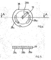
- the valve 18 is constituted from two parts 19, 20, well represented respectively in FIGS. 4, 5 and 6 to 8.
- the part 20 is fixed and receives the various connection channels previously indicated in the form of through holes.
- the portion 19 is rotatably mounted to provide a plurality of circuit configurations according to the relative angular position it occupies with respect to the fixed portion 20.
- the communication of different connection channels 21 to 26, have on the fixed part 20 is effected by means of communication here in the form of oblong blind holes 28 a, b, c, which stand out particularly from FIGS. 4 and 5.
- the oblong hole 28c ensures communication between the connection channels 25 , 26, or 26 and 23, according to the relative positions of the movable portion 19 and the fixed portion 20.
- the oblong hole 28b ensures the communication of the connection path 24 (from the pump 12) and the connection way 25 (to the hydraulic cylinder 4).
- the oblong hole 28a allows the communication channel 21 and the connection channel 22 to be put in communication to open the discharge circuit 17 or of the channel 21 with the channel 23 to produce hot water or water. steam.
- the communication command of the valve 18 can be operated in different ways, and in particular by motorized actuation or, more simply, by means of a manually operable lever 35, an example of which is shown in FIG. also illustrated an example of mounting of the valve 18.
- the fixed portion 20 is attached to a casing 33 connecting the connecting tracks 21 to 26.
- the seal is provided by a seal 32 for example silicone.
- the working face that which comprises the oblong holes 28a, b, c
- the disc portion forms a rotation drive under the effect of the lever 35.
- the power transmission between the lever 35 and the movable portion 19 is effected by a coupler 31 which also allows the assembly of all on a support 30.
- FIG. 1 This configuration is illustrated in Figure 1.
- the machine is not in the production position, in particular, a pod 8 is here being introduced but is not yet in the brewing chamber 1.
- the closing means of the infusion chamber 1 are inactivated, which is represented by a retracted position of the piston 5 of the cylinder 4.
- the pump 12 is also inactive, and the valve is such that the connection channels 24 and 25 are are not connected, avoiding the actuation of the cylinder 4.
- the channel 24 is in communication with the connection channel 26 ensuring the purge circuit 27 of the hydraulic cylinder 4 by return to the water source 15.
- the boiler 11 and the discharge outlet 17 are in communication in order to avoid any overpressure in the boiler 11, by means of a communication of the heating channels. connection 21 and 22, through the slot 28 a.
- a dose 8 has been introduced and is present in the infusion chamber 1.
- the movable portion 19 of the valve 18 has been rotated in the direction indicated by the arrow in FIG. 2. This rotation ensures through the oblong hole 28b, the connection of the connection channels 24 and 25, so as to supply the hydraulic cylinder 4 with pressurized water from the pump 12.
- This supply of the inlet 6 of the cylinder has the effect of causing the translation of the piston 5 which ensures the closure of the infusion chamber 1 by the movement of the movable portion 3 of said chamber 1.
- a valve 37 calibrated at a predetermined pressure is located at the outlet of the boiler 11, upstream of the brewing chamber 1, avoids the circulation of water to the brewing chamber 1 before having reached a pressure predetermined for the valve does not open before closing the infusion chamber under the actuation of the cylinder 4.
- valve 37 opens and ensures the circulation of water between the boiler 11 and the brewing chamber 1 to produce the hot drink that flows through the outlet 7.
- connection channels 21, 22, and 23 are not connected to the outlet of the boiler 11.
- the machine according to the invention is equipped with an outlet 16 for delivering hot water or steam to the user. Delivery of hot water is effected with full actuation of the pump 12. For the production of steam, the pump 12 is inactive or active intermittently.
- the valve 18 is here configured so as to put in communication the connection tracks 21 and 23 ensuring the flow of the hot water from the boiler 11 to the outlet 16.
- the other channels are not in communication.
- the jack 4 remains inactive since the connection path 24 is plugged.
- the infusion chamber 1 remains open and waiting for the introduction of a dose 8.
Abstract
Description
La présente invention concerne une machine pour la production de boissons par infusion d'eau chaude.The present invention relates to a machine for the production of beverages by infusion of hot water.
Elle s'appliquera particulièrement à la réalisation de machines pour la fabrication de cafés de type expresso.It will particularly apply to the production of machines for the manufacture of espresso-type coffees.
De telles machines comprennent une chambre d'infusion apte à recevoir la matière à infuser telle de la mouture de café. Cette chambre est reliée à un circuit de distribution d'eau chaude permettant son injection dans la chambre d'infusion et l'évacuation de la boisson par une sortie. Dans certaines machines, la chambre d'infusion peut être ouverte ou fermée suivant les phases de production et, en particulier l'admission de la mouture, l'infusion et l'éjection de la mouture. De telles machines à chambre d'infusion aptes à être ouvertes ou fermées, sont particulièrement utilisées dans le domaine des machines utilisant des doses de mouture de café préemballées. Des doses du type présentées dans le document
Les phase d'ouverture et de fermeture de la chambre d'infusion servent dans cette application préférée à admettre la dose, à fermer la chambre d'infusion pour extraction et à l'ouvrir enfin pour éjecter la dose usagée.The opening and closing phases of the infusion chamber are used in this preferred application to admit the dose, to close the extraction brewing chamber and finally to open to eject the used dose.
Ce type de machine nécessite un circuit d'eau chaude pour l'injection dans la chambre d'infusion, et éventuellement la livraison additionnelle d'eau chaude ou de vapeur d'eau à l'usager par une buse supplémentaire. En outre, des moyens de fermeture sont à prévoir pour ouvrir ou fermer la chambre d'infusion. Ces moyens utilisent généralement un circuit hydraulique de commande, et présentent un vérin dont le piston est apte à translater pour les phases de fermeture et d'ouverture de la chambre d'infusion.This type of machine requires a hot water circuit for injection into the brewing chamber, and possibly the additional delivery of water hot water or steam to the user through an additional nozzle. In addition, closure means are to be provided to open or close the brewing chamber. These means generally use a hydraulic control circuit, and have a cylinder whose piston is able to translate for the closing and opening phases of the brewing chamber.
Il ressort que plusieurs circuits hydrauliques sont présents ce qui induit une multiplicité de vannes et en particulier des électrovannes.It appears that several hydraulic circuits are present which induces a multiplicity of valves and in particular solenoid valves.
Le document
On connaît de
Ces deux documents montrent uniquement la gestion d'un circuit classique d'eau chaude.These two documents only show the management of a conventional hot water circuit.
Il existe donc un besoin de rationaliser la configuration des circuits hydrauliques dans des machines à café en vue de limiter le nombre de vannes nécessaires à la réalisation des différentes configurations de circuit au cours du fonctionnement.There is therefore a need to rationalize the configuration of hydraulic circuits in coffee machines in order to limit the number of valves necessary to achieve the various circuit configurations during operation.
La présente invention s'inscrit dans ce cadre, et propose pour ce faire une machine améliorée pour la production de boissons, par infusion d'eau chaude comprenant une chambre d'infusion reliée à un circuit de distribution d'eau chaude et apte à être ouverte ou fermée par des moyens de fermeture reliés à un circuit hydraulique de commande. Le circuit de distribution d'eau chaude et le circuit hydraulique de commande sont configurés par la même vanne.The present invention is part of this framework, and proposes for this purpose an improved machine for the production of beverages, by infusion of hot water comprising an infusion chamber connected to a hot water distribution circuit and able to be open or closed by closure means connected to a hydraulic control circuit. The water distribution circuit hot and the hydraulic control circuit are configured by the same valve.
Cette machine pourra se présenter suivant des variantes préférées introduites ci-après :
- les moyens de fermeture comportent un vérin hydraulique actionné par une pompe hydraulique ;
- la vanne comporte des voies de connection au circuit de distribution d'eau chaude, à une sortie de décharge d'eau chaude, à la sortie de la pompe hydraulique, au vérin hydraulique et à un circuit de purge du vérin;
- the closing means comprise a hydraulic jack actuated by a hydraulic pump;
- the valve comprises connection channels to the hot water distribution circuit, to a discharge outlet for hot water, at the outlet of the hydraulic pump, the hydraulic cylinder and a purge circuit of the cylinder;
La vanne comporte une voie de connection d'une sortie d'eau chaude, et des moyens de mise en communication de la voie de connection du circuit de distribution d'eau chaude soit à la voie de connection de la sortie de décharge d'eau chaude, soit à la voie de connection de la sortie d'eau chaude.The valve comprises a connection channel for a hot water outlet, and means for communicating the connection path of the hot water distribution circuit with the connection channel of the water discharge outlet. hot, either to the connection way of the hot water outlet.
La vanne comporte une partie fixe dotée des voies de connection et une partie mobile dotée des moyens de mise en communication, la position relative de la partie fixe et de la partie mobile définissant la configuration du circuit de distribution d'eau chaude et du circuit hydraulique de commande.The valve comprises a fixed part provided with connection channels and a mobile part provided with communication means, the relative position of the fixed part and the mobile part defining the configuration of the hot water distribution circuit and the hydraulic circuit. control.
La partie mobile est mobile en rotation relativement à la partie fixe.The movable portion is rotatable relative to the fixed portion.
La partie mobile est actionnée en rotation par un levier.The moving part is actuated in rotation by a lever.
La pompe hydraulique est commune au circuit hydraulique de commande et au circuit de distribution d'eau chaude.The hydraulic pump is common to the hydraulic control circuit and the hot water distribution circuit.
La circuit de distribution d'eau chaude et le circuit hydraulique de commande sont alimentés par une même source d'eau.The hot water distribution circuit and the hydraulic control circuit are fed by the same water source.
Le circuit de purge du vérin est relié à la source d'eau.The purge circuit of the cylinder is connected to the water source.
Le circuit de distribution d'eau chaude comporte une chaudière reliée à un circuit d'injection dans la chambre d'infusion, ledit circuit d'injection comportant un clapet taré à une pression prédéterminée.The hot water distribution circuit comprises a boiler connected to an injection circuit in the infusion chamber, said injection circuit comprising a valve calibrated at a predetermined pressure.
Les dessins ci-joints sont donnés à titre d'exemples et ne sont pas limitatifs de l'invention. Ils représentent seulement un mode de réalisation de l'invention et permettront de la comprendre aisément.
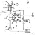
- La figure 1 montre un schéma de certains composants d'une machine de l'invention et des circuits d'eau chaude et hydraulique qui sont présentés dans une position d'arrêt de la machine.
- La figure 2 montre ce même schéma mais dans une position d'extraction pour la production de la boisson chaude.
- La figure 3 montre une autre configuration du circuit pour la livraison d'eau chaude par une sortie d'eau chaude ou de vapeur.
- La figure 4 montre un exemple de réalisation d'une partie mobile d'une vanne utilisable selon l'invention en vue de dessus.
- La figure 5 en est une vue en coupe.
- La figure 6 montre un mode préféré de réalisation d'une partie fixe d'une vanne utilisable selon l'invention en vue de dessus.
- La figure 7 en est une vue en coupe et la figure 8 est en une vue dessous.
- La figure 9 est une vue éclatée illustrant différents composants d'une vanne utilisable selon l'invention.
- Les figures 10 à 12 schématisent trois positions de fonctionnement possibles pour la chambre d'infusion.
- Fig. 1 shows a diagram of certain components of a machine of the invention and hot and hydraulic water circuits which are presented in a stopping position of the machine.
- Figure 2 shows the same diagram but in an extraction position for the production of the hot drink.
- Figure 3 shows another configuration of the circuit for the delivery of hot water through a hot water outlet or steam.
- FIG. 4 shows an exemplary embodiment of a mobile part of a valve that can be used according to the invention in a view from above.
- Figure 5 is a sectional view.
- FIG. 6 shows a preferred embodiment of a fixed part of a valve that can be used according to the invention in a view from above.
- Figure 7 is a sectional view and Figure 8 is in a view below.
- Figure 9 is an exploded view illustrating different components of a valve usable according to the invention.
- Figures 10 to 12 show three possible operating positions for the brewing chamber.
La machine de production de boissons selon l'invention comprend une chambre d'infusion apte à être ouverte et fermée par des moyens de fermeture.The beverage production machine according to the invention comprises an infusion chamber able to be opened and closed by closure means.
A titre préféré, cela est réalisé par l'intermédiaire d'une chambre 1 constituée en deux portions, l'une fixe 2, et l'autre mobile 3, bien que cet exemple ne soit pas limitatif. La portion mobile 3 est en particulier apte à être rapprochée ou éloignée de la portion fixe par l'intermédiaire d'un actionnement en translation réalisé par les moyens de fermeture. Toujours à titre préféré, ces moyens de fermeture sont constitués d'un vérin hydraulique 4 dont le piston 5 réalise l'actionnement en translation de la portion mobile 3 de la chambre d'infusion 1.As a preference, this is achieved by means of a chamber 1 constituted in two portions, one fixed 2, and the other mobile 3, although this example is not limiting. The movable portion 3 is in particular adapted to be moved towards or away from the fixed portion by means of translation actuation carried out by the closing means. Still preferably, these closing means consist of a hydraulic jack 4 whose piston 5 carries out the actuation in translation of the movable portion 3 of the brewing chamber 1.
Les figures 10 à 12 illustrent à titre purement indicatif des phase de fonctionnement de l'invention pour une machine utilisant des doses 8.Figures 10 to 12 illustrate purely indicative operating phases of the invention for a machine using doses 8.
A titre additionnel, des moyens de guidage d'une portion latérale de la dose 8 peuvent être prévus au niveau de la chambre d'infusion 1 tel que cela est représenté au repère 36 sur la figures 10 à 12.In addition, means for guiding a lateral portion of the dose 8 may be provided at the infusion chamber 1 as shown at
Le vérin hydraulique est relié à un circuit hydraulique de commande 10 qui peut être configuré pour autoriser l'admission de fluides dans le corps du vérin ou son évacuation suivant les phases de fonctionnement. La mise en pression du fluide (ici constitué par de l'eau) est réalisée par une pompe hydraulique 12 avantageusement commune avec la pompe utilisée pour l'injection d'eau chaude dans la chambre d'infusion.The hydraulic cylinder is connected to a
La pompe 12 est alimentée en eau par une source sous forme d'un bac représenté par le repère 15 aux figures 1 à 3. En aval de la pompe 12, une chaudière 11 est présente pour assurer l'amenée en température de l'eau avant l'injection dans la chambre d'infusion 1.The
En position de repos, l'eau n'est pas admise dans la chambre d'infusion, et un éventuel surplus doit être déchargé par l'intermédiaire d'une sortie de décharge 17 qui peut déboucher sur un bac de récupération.In the rest position, water is not admitted into the brewing chamber, and any surplus must be discharged via a discharge outlet 17 which can lead to a recovery tank.
En outre, une sortie d'eau chaude 16 peut également être prévue pour assurer la livraison d'eau chaude à l'utilisateur ou la production de vapeur suivant l'état d'actionnement et d'activation de la pompe.In addition, a
Ces différents éléments constitutifs de machines, sont reliés par un circuit de distribution d'eau chaude (pour la partie liée à la production de boissons, la livraison d'eau chaude, et la production de vapeur), et par un circuit hydraulique de commande (pour l'actionnement des moyens de fermeture). De façon caractéristique, la configuration de ces deux circuits est assurée par une même vanne.These different components of machines, are connected by a hot water distribution circuit (for the part related to the production of drinks, the delivery of hot water, and the production of steam), and by a hydraulic control circuit (for actuating the closing means). Characteristically, the configuration of these two circuits is provided by the same valve.
Cette vanne 18 est représentée dans différents états aux figures 1 à 3.This
Comme cela ressort des figures 1 à 3 et des figures 6 à 8, la vanne 18 comporte une pluralité de voies de connection aux éléments des circuits.As can be seen in FIGS. 1 to 3 and in FIGS. 6 to 8, the
En particulier, en ce qui concerne le circuit hydraulique de commande 10, la vanne 18 comporte une voie de connection 25 au vérin hydraulique 4 ainsi qu'une voie de connection 26 a un circuit de purge 27. En outre, une voie de connection 24 est prévue pour relier la vanne 18 à une sortie 13 de la pompe 12 afin d'admettre de l'eau sous pression pour la commande du vérin hydraulique 4.In particular, with regard to the
En ce qui concerne le circuit de distribution d'eau chaude 9, la vanne 18 comporte une voie de connection 21 à ce circuit, en provenance de la chaudière 11. Le circuit 9 peut être mis en connection par l'intermédiaire de la vanne 18 avec une sortie de décharge 17 par l'intermédiaire d'une voie de connection 22.With regard to the hot
A titre préféré, la vanne 18 est constituée à partir de deux parties 19, 20, bien représentées respectivement aux figures 4, 5, et 6 à 8. La partie 20 est fixe et reçoit les différentes voies de connection précédemment indiquées sous forme de trous débouchants. La partie 19 est montée mobile en rotation pour assurer plusieurs configuration de circuit suivant la position angulaire relative qu'elle occupe par rapport à la partie fixe 20.La mise ne communication de différentes voies de connection 21 à 26, présentent sur la partie fixe 20, s'effectue par des moyens de mise en communication ici sous la forme de trous borgnes oblongs 28 a, b, c, qui ressortent particulièrement des figures 4 et 5. Le trou oblong 28 c assure une mise en communication des voies de connection 25, 26, ou 26 et 23, selon les position relatives de la partie mobile 19 et de la partie fixe 20. Le trou oblong 28 b assure la mise en communication de la voie de connection 24 (issue de la pompe 12) et de la voie de connection 25 (vers le vérin hydraulique 4).Preferably, the
Enfin, le trou oblong 28 a permet la mise en communication de la voie de connection 21 et de la voie de connection 22 pour ouvrir le circuit de décharge 17 ou de la voie 21 avec la voie 23 pour produire de l'eau chaude ou de la vapeur. La commande de communication de la vanne 18 peut être opérée de différentes façon, et notamment par une actionnement motorisé ou, plus simplement, par l'intermédiaire d'un levier 35 actionnable manuellement dont un exemple est représentée en figure 9. A cette figure on a également illustré un exemple de montage de la vanne 18. Dans ce cadre, la partie fixe 20 est rapportée sur un carter 33 de raccordement des voies de connections 21 à 26. L'étanchéité est assurée par un joint 32 par exemple en silicone.Finally, the
Sur la phase de travail de la partie fixe 20 s'applique la face de travail (celle qui comporte les trous oblongs 28a, b, c) de la partie mobile 19. Un plat 38 réalisé sur le pourtour de la partie mobile 19 ici sous forme de portion de disque tout comme la partie fixe 20, assure l'entraînement en rotation sous l'effet du levier 35. La transmission de puissance entre le levier 35 et la partie mobile 19 est opérée par un coupleur 31 permettant également le montage de l'ensemble sur un support 30.On the working phase of the fixed
On notera que cette configuration a l'avantage de ne nécessiter aucune commande électrique pour assurer le choix des configurations de fonctionnement de la vanne 18.Note that this configuration has the advantage of not requiring any electrical control to ensure the choice of operating configurations of the
On expose ci-après plus précisément le mode de fonctionnement de la machine selon l'invention, suivant trois positions successives de la vanne 18.The method of operation of the machine according to the invention is described below in three successive positions of the
Cette configuration est illustrée en figure 1. Dans ce cadre, la machine n'est pas en position de production, en particulier, une dosette 8 est ici en cours d'introduction mais n'est pas encore dans la chambre d'infusion 1. Les moyens de fermeture de la chambre d'infusion 1 sont inactivés ce qui est représenté par une position de retrait du piston 5 du vérin 4. La pompe 12 est également inactive, et la vanne est telle que les voies de connection 24 et 25 ne sont pas reliées, évitant l'actionnement du vérin 4. Par contre, la voie 24 est en communication avec la voie de connection 26 assurant le circuit de purge 27 du vérin hydraulique 4 par retour à la source d'eau 15.This configuration is illustrated in Figure 1. In this context, the machine is not in the production position, in particular, a pod 8 is here being introduced but is not yet in the brewing chamber 1. The closing means of the infusion chamber 1 are inactivated, which is represented by a retracted position of the piston 5 of the cylinder 4. The
En ce qui concerne le circuit de distribution d'eau chaude 9, la chaudière 11 et la sortie de décharge 17 sont en communication afin d'éviter toute surpression dans la chaudière 11, par l'intermédiaire d'une mise en communication des voies de connection 21 et 22, par le trou oblong 28 a.With regard to the hot
Dans ce cadre, une dose 8 a été introduite et est présente dans la chambre d'infusion 1. La partie mobile 19 de la vanne 18 a été tournée dans le sens indiqué par la flèche en figure 2. Cette rotation assure par l'intermédiaire du trou oblong 28 b, la mise en communication des voies de connection 24 et 25, de façon à alimenter le vérin hydraulique 4 en eau sous pression issue de la pompe 12. Cette alimentation de l'entrée 6 du vérin a pour effet de provoquer la translation du piston 5 qui assure la fermeture de la chambre d'infusion 1 par le mouvement de la portion mobile 3 de ladite chambre 1.In this context, a dose 8 has been introduced and is present in the infusion chamber 1. The
Durant cette phase d'actionnement du vérin 4, et bien que la pompe 12 soit activée, le passage d'eau chaude dans la chambre d'infusion n'est pas encore produite. En effet, un clapet 37 taré à une pression prédéterminée est situé en sortie de la chaudière 11, en amont de la chambre d'infusion 1, évite la circulation d'eau vers la chambre d'infusion 1 avant d'avoir atteint une pression prédéterminée choisie pour que la clapet ne s'ouvre pas avant la fermeture de la chambre d'infusion sous l'actionnement du vérin 4.During this phase of actuation of the cylinder 4, and although the
Dès que la pression prédéterminée est atteinte, le clapet 37 s'ouvre et assure la circulation d'eau entre la chaudière 11 et la chambre d'infusion 1 pour produire la boisson chaude qui s'écoule par l'intermédiaire de la sortie 7.As soon as the predetermined pressure is reached, the
Durant cette phase de fonctionnement, les voies de connection 21, 22, et 23, ne sont pas reliées à la sortie de la chaudière 11.During this operating phase, the
A titre avantageux mais non limitatif, la machine selon l'invention est équipée d'une sortie 16 de livraison d'eau chaude ou de vapeur à l'utilisateur. La livraison d'eau chaude s'effectue avec un actionnement complet de la pompe 12. Pour la production de vapeur, la pompe 12 est inactive ou active par intermittence.Advantageously, but not limited to, the machine according to the invention is equipped with an
Cette phase de réalisation est illustrée à la figure 3. Elle s'obtient par rotation de la partie mobile 19 de la vanne 18 dans le sens trigonométrique depuis la position d'arrêt représentée à la figure 1 et exposée précédemment.This embodiment is illustrated in Figure 3. It is obtained by rotating the
En référence à la figure 3, la vanne 18 est ici configurée de façon à mettre en communication les voies de connection 21 et 23 assurant l'écoulement de l'eau chaude depuis la chaudière 11 jusqu'à la sortie 16. Par contre, les autres voies ne sont pas en communication. En particulier, le vérin 4 reste inactif puisque la voie de connection 24 est bouchée. Dans ce cadre, la chambre d'infusion 1 reste ouverte et en attente de l'introduction d'une dose 8.With reference to FIG. 3, the
Dès que l'utilisateur souhaite stopper l'apport d'eau chaude ou de vapeur, il lui suffit de tourner le levier 35 dans le sens inverse pour remettre la vanne 18 en position d'arrêt représentée à la figure 1.As soon as the user wishes to stop the supply of hot water or steam, he only has to turn the
- 1. Chambre d'infusion1. Infusion chamber
- 2. Portion fixe2. Fixed portion
- 3. Portion mobile3. Mobile portion
- 4. Vérin4. Cylinder
- 5. Piston5. Piston
- 6. Entrée de fluide6. Fluid inlet
- 7. Sortie de boisson7. Drink outlet
- 8. dose8. dose
- 9. Circuit de distribution d'eau chaude9. Hot water distribution circuit
- 10. Circuit hydraulique de commande10. Control hydraulic circuit
- 11. Chaudière11. Boiler
- 12. Pompe hydraulique12. Hydraulic pump
- 13. Sortie de pompe13. Pump outlet
- 14. Sortie de pompe14. Pump outlet
- 15. Source d'eau15. Source of water
- 16. Sortie d'eau chaude16. Hot water outlet
- 17. Sortie de décharge17. Discharge outlet
- 18. Vanne18. Valve
- 19. Partie mobile19. Moving part
- 20. Partie fixe20. Fixed part
- 21. Voie de connection au circuit de distribution21. Connection channel to the distribution circuit
- 22. Voie de connection à la sortie de décharge22. Connection channel to the discharge outlet
- 23. Voie de connection à la sortie d'eau chaude23. Connecting way to the hot water outlet
- 24. Voie de connection à la sortie de la pompe hydraulique24. Connection channel at the outlet of the hydraulic pump
- 25. Voie de connection au vérin hydraulique25. Connection channel to the hydraulic cylinder
- 26. Voie de connection au circuit de purge26. Connection channel to the purge circuit
- 27. Circuit de purge27. Purge circuit
- 28 a, b, c - Trou borgne oblong28 a, b, c - Oblong blind hole
- 30. Support30. Support
- 31. Coupleur31. Coupler
- 32. Joint32. Joint
- 33. Carter de raccordement33. Connection housing
- 35. Levier35. Leverage
- 36. Moyen de guidage36. Guide means
- 37. Clapet taré37. Failed flapper
- 38. Plat38. Dish
Claims (7)
- Machine for the production of beverages by infusion of hot water comprising an infusion chamber (1) connected to a hot water distribution circuit (9) configured by a valve (18) comprising connecting channels (22, 23) to the hot water distribution circuit (9) and to a hot water discharge outlet (17) and comprising means for bringing the connecting channel (21) to the hot water distribution circuit (9) into communication with the connecting channel (22) of the hot water discharge outlet (17), the valve (18) comprising a fixed portion (20) equipped with the connecting channels (21, 22) and a portion (19) which is mobile in rotation relative to the fixed portion (20) and equipped with the communicating means, the relative position of the fixed portion (20) and the mobile portion (19) defining the configuration of the hot water distribution circuit (9),
characterised in that- the infusion chamber is capable of being opened or closed by closing means connected to a hydraulic control circuit (10), in which the hot water distribution circuit (9) and the hydraulic control circuit (10) are configured by the same valve (18);- the closing means comprise a hydraulic jack (4) actuated by a hydraulic pump (12);- the valve (18) comprises connecting channels (24, 25, 26) to the outlet (13) of the hydraulic pump (12), to the hydraulic jack (4) and to a jack purging circuit (27);- the valve (18) comprises means for bringing the connecting channel (25) of the hydraulic jack (4) into communication with either the connecting channel (24) of the outlet of the hydraulic pump (12) or with the connecting channel (26) of the purging circuit (27) of the jack (4). - Machine according to claim 1,
characterised in that
the valve (18) comprises a connecting channel (23) of an outlet for hot water (16), and means for bringing the connecting channel (21) of the hot water distribution circuit (9) into communication either with the connecting channel (22) of the hot water discharge outlet (17) or with the connecting channel (23) of the hot water outlet (16). - Machine according to claim 1 or 2,
characterised in that
the mobile portion (19) is actuated in rotation by a lever (35). - Machine according to any one of claims 1 to 3,
characterised in that
the hydraulic pump (12) is common to the hydraulic control circuit (10) and to the hot water distribution circuit (9). - Machine according to any one of claims 1 to 4,
characterised in that
the hot water distribution circuit (9) and the hydraulic control circuit (10) are supplied by one and the same source of water (15). - Machine according to any one of claims 2 to 4 in combination with claim 5,
characterised in that
the purging circuit (27) of the jack (4) is connected to the source of water (15). - Machine according to any one of claims 1 to 6,
characterised in that
the hot water distribution circuit (9) comprises a boiler (11) connected to an injection circuit into the infusion chamber (1), said injection circuit comprising a valve (37) calibrated at a predetermined pressure.
Applications Claiming Priority (3)
| Application Number | Priority Date | Filing Date | Title |
|---|---|---|---|
| FR0211665 | 2002-09-16 | ||
| FR0211665A FR2844441B1 (en) | 2002-09-16 | 2002-09-16 | MACHINE FOR THE PRODUCTION OF DRINK BY HOT WATER INFUSION |
| PCT/FR2003/050054 WO2004041039A1 (en) | 2002-09-16 | 2003-09-12 | Machine for producing a beverage by hot water infusion |
Publications (2)
| Publication Number | Publication Date |
|---|---|
| EP1545278A1 EP1545278A1 (en) | 2005-06-29 |
| EP1545278B1 true EP1545278B1 (en) | 2007-11-07 |
Family
ID=31897508
Family Applications (1)
| Application Number | Title | Priority Date | Filing Date |
|---|---|---|---|
| EP03780267A Expired - Lifetime EP1545278B1 (en) | 2002-09-16 | 2003-09-12 | Machine for producing a beverage by hot water infusion |
Country Status (7)
| Country | Link |
|---|---|
| EP (1) | EP1545278B1 (en) |
| AT (1) | ATE377372T1 (en) |
| AU (1) | AU2003288360A1 (en) |
| DE (1) | DE60317357T2 (en) |
| ES (1) | ES2297246T3 (en) |
| FR (1) | FR2844441B1 (en) |
| WO (1) | WO2004041039A1 (en) |
Cited By (2)
| Publication number | Priority date | Publication date | Assignee | Title |
|---|---|---|---|---|
| ITRM20110329A1 (en) * | 2011-06-23 | 2012-12-24 | Gardosi Massimiliano | COMPENSATOR FOR APPLIANCES HOT SPREADERS, PREFERABLY PRE-DOSED, IN PARTICULAR FOR PODS COFFEE MACHINES. |
| WO2018158179A1 (en) * | 2017-02-28 | 2018-09-07 | Nestec Sa | Dispenser with parallel dispensing paths |
Families Citing this family (12)
| Publication number | Priority date | Publication date | Assignee | Title |
|---|---|---|---|---|
| RU2525068C2 (en) | 2009-10-05 | 2014-08-10 | Нестек С.А. | Device for extraction of cartridge |
| PT2506745E (en) | 2009-12-01 | 2013-11-28 | Nestec Sa | Cartridge extraction device |
| EP2353469A1 (en) | 2010-02-03 | 2011-08-10 | Nestec S.A. | Beverage preparation machine for large size beverages |
| FR2960406B1 (en) * | 2010-05-25 | 2013-01-11 | Cie Mediterraneenne Des Cafes | INFUSION BEVERAGE PRODUCTION SYSTEM |
| EP2575573B1 (en) * | 2010-05-25 | 2015-07-08 | Compagnie Mediterraneenne Des Cafes | System for making beverages by infusion |
| IT1402180B1 (en) * | 2010-09-09 | 2013-08-28 | Sgl Italia S R L Con Unico Socio | INFUSER GROUP FOR THE PRODUCTION OF A BEVERAGE |
| BR112014004231A2 (en) | 2011-08-25 | 2017-03-21 | Nestec Sa | cartridge positioning system |
| CA2843541A1 (en) | 2011-08-25 | 2013-02-28 | Nestec S.A. | Long-lasting cartridge piercer |
| EP2747611B1 (en) | 2011-08-25 | 2017-09-27 | Nestec S.A. | Cartridge chamber of extraction system |
| EP2747610B1 (en) | 2011-08-25 | 2018-02-28 | Nestec S.A. | Cartridge removal system |
| DE102013210108A1 (en) * | 2013-05-29 | 2014-12-04 | BSH Bosch und Siemens Hausgeräte GmbH | Fully automatic coffee machine with motorized multi-way valve |
| BR112017028578B1 (en) * | 2015-07-03 | 2021-11-09 | Saga Coffee S.P.A. | BEVERAGE PRODUCTION MACHINE |
Family Cites Families (6)
| Publication number | Priority date | Publication date | Assignee | Title |
|---|---|---|---|---|
| DE1454102B2 (en) * | 1962-09-01 | 1971-10-28 | Organizzazione Novi S.r.l., Mailand (Italien) | INDEPENDENT COFFEE MACHINE FOR PREPARING ESPRESSO COFFEE IN PORTIONS |
| FR2709655B1 (en) | 1993-09-06 | 1995-11-24 | Cafes Cie Mediterraneenne | Express coffee machine using ground coffee packaging of the pre-dosed tablet type. |
| DE4427745A1 (en) * | 1994-08-05 | 1996-02-01 | Braun Ag | Multi-layer distribution valve seal for espresso coffee machine |
| FR2801774B1 (en) * | 1999-12-01 | 2004-02-20 | Moulinex Sa | SPRESSO COFFEE MACHINE WATER DISPENSING KIT |
| ATE249777T1 (en) * | 2000-12-29 | 2003-10-15 | Sgl Italia Srl | COFFEE MACHINE |
| CH694265A5 (en) | 2001-01-24 | 2004-10-29 | Monodor Sa | Water injection device for an apparatus for the preparation of a beverage from a capsule containing the product to be extracted. |
-
2002
- 2002-09-16 FR FR0211665A patent/FR2844441B1/en not_active Expired - Fee Related
-
2003
- 2003-09-12 WO PCT/FR2003/050054 patent/WO2004041039A1/en active IP Right Grant
- 2003-09-12 EP EP03780267A patent/EP1545278B1/en not_active Expired - Lifetime
- 2003-09-12 AU AU2003288360A patent/AU2003288360A1/en not_active Abandoned
- 2003-09-12 DE DE60317357T patent/DE60317357T2/en not_active Expired - Lifetime
- 2003-09-12 ES ES03780267T patent/ES2297246T3/en not_active Expired - Lifetime
- 2003-09-12 AT AT03780267T patent/ATE377372T1/en not_active IP Right Cessation
Cited By (2)
| Publication number | Priority date | Publication date | Assignee | Title |
|---|---|---|---|---|
| ITRM20110329A1 (en) * | 2011-06-23 | 2012-12-24 | Gardosi Massimiliano | COMPENSATOR FOR APPLIANCES HOT SPREADERS, PREFERABLY PRE-DOSED, IN PARTICULAR FOR PODS COFFEE MACHINES. |
| WO2018158179A1 (en) * | 2017-02-28 | 2018-09-07 | Nestec Sa | Dispenser with parallel dispensing paths |
Also Published As
| Publication number | Publication date |
|---|---|
| DE60317357T2 (en) | 2008-08-21 |
| ATE377372T1 (en) | 2007-11-15 |
| AU2003288360A1 (en) | 2004-06-07 |
| WO2004041039A1 (en) | 2004-05-21 |
| FR2844441B1 (en) | 2006-03-31 |
| EP1545278A1 (en) | 2005-06-29 |
| ES2297246T3 (en) | 2008-05-01 |
| FR2844441A1 (en) | 2004-03-19 |
| DE60317357D1 (en) | 2007-12-20 |
Similar Documents
| Publication | Publication Date | Title |
|---|---|---|
| EP1545278B1 (en) | Machine for producing a beverage by hot water infusion | |
| CA2435445C (en) | Water injection device for an apparatus for preparing a beverage from a capsule | |
| EP1583446B1 (en) | Substance-extraction device and machine for producing drinks | |
| EP2020891B1 (en) | Machine for producing espresso-type coffee | |
| EP2083662A1 (en) | Assembly comprising an appliance and a disposable capsule for producing a brewed drink, and capsule for such an assembly | |
| EP1480540A1 (en) | Device for producing beverage by infusion | |
| EP1867258A2 (en) | Powdery product dispenser with removable reservoir | |
| WO2007036634A1 (en) | Water softener with dual-mode regeneration | |
| FR2960405A1 (en) | PRESSURE VARIATION INFUSION DEVICE | |
| FR2912664A1 (en) | Coffee brewing apparatus, has isolation unit including valve to cause abrupt relaxation of compressed air in water reservoir and air flow along pressure curve until end of infusion cycle during inactive state of pressurization unit | |
| EP1635679B1 (en) | Device for production of a beverage by infusion | |
| EP3013192A1 (en) | Device for preparing infused drinks, comprising an injection tube leading into the infusion chamber | |
| EP1635681B1 (en) | Device for producing a drink by infusion | |
| EP2385778B1 (en) | Percolation device | |
| EP3013193B1 (en) | Device for preparing infused drinks, comprising a pivoting capsule support | |
| EP2575560A1 (en) | System for making beverages by infusing | |
| EP2575573B1 (en) | System for making beverages by infusion | |
| EP2575565B2 (en) | System for making beverages by infusion | |
| FR2639205A1 (en) | AUTOMATIC COFFEE MACHINE COMPRISING A CIRCULAR MOBILE TRAY PERCE OF ALVEOLES HAVING BETWEEN TWO FIXED TRAYS, THE CIRCULAR MOVEMENT PROVIDING THE DIFFERENT PHASES OF THE PREPARATION OF THE COFFEE WITH A SEALING OF EACH ALVEOLE | |
| EP2632309B1 (en) | Appliance for making infusions, of the reversible type | |
| EP1677652B1 (en) | Improvements to percolator groups having a moving brewing chamber | |
| FR2960406A1 (en) | Machine for making beverage i.e. espresso coffee, has discharge valve arranged in upstream of activator and arranged in manner such that opening of discharge valve reduces pressure of fluid in upstream of activator | |
| FR2695020A1 (en) | Coffee maker mainly for espresso coffee - has distribution member with sliding airtight joint connecting reservoir to heating block or connecting heating block to draining pipe | |
| CA2916084A1 (en) | Device for preparing infused drinks, comprising a capsule positioning means | |
| FR2723524A1 (en) | Automatic machine for producing infusions of hot beverages such as coffee |
Legal Events
| Date | Code | Title | Description |
|---|---|---|---|
| PUAI | Public reference made under article 153(3) epc to a published international application that has entered the european phase |
Free format text: ORIGINAL CODE: 0009012 |
|
| 17P | Request for examination filed |
Effective date: 20050311 |
|
| AK | Designated contracting states |
Kind code of ref document: A1 Designated state(s): AT BE BG CH CY CZ DE DK EE ES FI FR GB GR HU IE IT LI LU MC NL PT RO SE SI SK TR |
|
| AX | Request for extension of the european patent |
Extension state: AL LT LV MK |
|
| DAX | Request for extension of the european patent (deleted) | ||
| GRAP | Despatch of communication of intention to grant a patent |
Free format text: ORIGINAL CODE: EPIDOSNIGR1 |
|
| RIN1 | Information on inventor provided before grant (corrected) |
Inventor name: BLANC, JEAN-PIERRE,OFF. MEDIT. DE BREV. D'I.&M. Inventor name: FERRIER, CHRISTIAN,OFF. MEDIT. DE BREV. D'I.&M. |
|
| GRAS | Grant fee paid |
Free format text: ORIGINAL CODE: EPIDOSNIGR3 |
|
| GRAA | (expected) grant |
Free format text: ORIGINAL CODE: 0009210 |
|
| AK | Designated contracting states |
Kind code of ref document: B1 Designated state(s): AT BE BG CH CY CZ DE DK EE ES FI FR GB GR HU IE IT LI LU MC NL PT RO SE SI SK TR |
|
| REG | Reference to a national code |
Ref country code: GB Ref legal event code: FG4D Free format text: NOT ENGLISH |
|
| REG | Reference to a national code |
Ref country code: IE Ref legal event code: FG4D Free format text: LANGUAGE OF EP DOCUMENT: FRENCH |
|
| REG | Reference to a national code |
Ref country code: CH Ref legal event code: EP |
|
| REF | Corresponds to: |
Ref document number: 60317357 Country of ref document: DE Date of ref document: 20071220 Kind code of ref document: P |
|
| REG | Reference to a national code |
Ref country code: CH Ref legal event code: NV Representative=s name: PATENTS & TECHNOLOGY SURVEYS SA |
|
| GBT | Gb: translation of ep patent filed (gb section 77(6)(a)/1977) |
Effective date: 20080211 |
|
| PG25 | Lapsed in a contracting state [announced via postgrant information from national office to epo] |
Ref country code: SE Free format text: LAPSE BECAUSE OF FAILURE TO SUBMIT A TRANSLATION OF THE DESCRIPTION OR TO PAY THE FEE WITHIN THE PRESCRIBED TIME-LIMIT Effective date: 20080207 |
|
| REG | Reference to a national code |
Ref country code: ES Ref legal event code: FG2A Ref document number: 2297246 Country of ref document: ES Kind code of ref document: T3 |
|
| PG25 | Lapsed in a contracting state [announced via postgrant information from national office to epo] |
Ref country code: SI Free format text: LAPSE BECAUSE OF FAILURE TO SUBMIT A TRANSLATION OF THE DESCRIPTION OR TO PAY THE FEE WITHIN THE PRESCRIBED TIME-LIMIT Effective date: 20071107 Ref country code: BG Free format text: LAPSE BECAUSE OF FAILURE TO SUBMIT A TRANSLATION OF THE DESCRIPTION OR TO PAY THE FEE WITHIN THE PRESCRIBED TIME-LIMIT Effective date: 20080207 |
|
| PG25 | Lapsed in a contracting state [announced via postgrant information from national office to epo] |
Ref country code: AT Free format text: LAPSE BECAUSE OF FAILURE TO SUBMIT A TRANSLATION OF THE DESCRIPTION OR TO PAY THE FEE WITHIN THE PRESCRIBED TIME-LIMIT Effective date: 20071107 |
|
| PG25 | Lapsed in a contracting state [announced via postgrant information from national office to epo] |
Ref country code: DK Free format text: LAPSE BECAUSE OF FAILURE TO SUBMIT A TRANSLATION OF THE DESCRIPTION OR TO PAY THE FEE WITHIN THE PRESCRIBED TIME-LIMIT Effective date: 20071107 Ref country code: CZ Free format text: LAPSE BECAUSE OF FAILURE TO SUBMIT A TRANSLATION OF THE DESCRIPTION OR TO PAY THE FEE WITHIN THE PRESCRIBED TIME-LIMIT Effective date: 20071107 |
|
| PG25 | Lapsed in a contracting state [announced via postgrant information from national office to epo] |
Ref country code: RO Free format text: LAPSE BECAUSE OF FAILURE TO SUBMIT A TRANSLATION OF THE DESCRIPTION OR TO PAY THE FEE WITHIN THE PRESCRIBED TIME-LIMIT Effective date: 20071107 Ref country code: SK Free format text: LAPSE BECAUSE OF FAILURE TO SUBMIT A TRANSLATION OF THE DESCRIPTION OR TO PAY THE FEE WITHIN THE PRESCRIBED TIME-LIMIT Effective date: 20071107 |
|
| PLBE | No opposition filed within time limit |
Free format text: ORIGINAL CODE: 0009261 |
|
| STAA | Information on the status of an ep patent application or granted ep patent |
Free format text: STATUS: NO OPPOSITION FILED WITHIN TIME LIMIT |
|
| PG25 | Lapsed in a contracting state [announced via postgrant information from national office to epo] |
Ref country code: PT Free format text: LAPSE BECAUSE OF FAILURE TO SUBMIT A TRANSLATION OF THE DESCRIPTION OR TO PAY THE FEE WITHIN THE PRESCRIBED TIME-LIMIT Effective date: 20080407 |
|
| REG | Reference to a national code |
Ref country code: IE Ref legal event code: FD4D |
|
| 26N | No opposition filed |
Effective date: 20080808 |
|
| PG25 | Lapsed in a contracting state [announced via postgrant information from national office to epo] |
Ref country code: IE Free format text: LAPSE BECAUSE OF FAILURE TO SUBMIT A TRANSLATION OF THE DESCRIPTION OR TO PAY THE FEE WITHIN THE PRESCRIBED TIME-LIMIT Effective date: 20071107 |
|
| PG25 | Lapsed in a contracting state [announced via postgrant information from national office to epo] |
Ref country code: GR Free format text: LAPSE BECAUSE OF FAILURE TO SUBMIT A TRANSLATION OF THE DESCRIPTION OR TO PAY THE FEE WITHIN THE PRESCRIBED TIME-LIMIT Effective date: 20080208 |
|
| PG25 | Lapsed in a contracting state [announced via postgrant information from national office to epo] |
Ref country code: FI Free format text: LAPSE BECAUSE OF FAILURE TO SUBMIT A TRANSLATION OF THE DESCRIPTION OR TO PAY THE FEE WITHIN THE PRESCRIBED TIME-LIMIT Effective date: 20071107 |
|
| PG25 | Lapsed in a contracting state [announced via postgrant information from national office to epo] |
Ref country code: EE Free format text: LAPSE BECAUSE OF FAILURE TO SUBMIT A TRANSLATION OF THE DESCRIPTION OR TO PAY THE FEE WITHIN THE PRESCRIBED TIME-LIMIT Effective date: 20071107 Ref country code: MC Free format text: LAPSE BECAUSE OF NON-PAYMENT OF DUE FEES Effective date: 20080930 |
|
| PG25 | Lapsed in a contracting state [announced via postgrant information from national office to epo] |
Ref country code: CY Free format text: LAPSE BECAUSE OF FAILURE TO SUBMIT A TRANSLATION OF THE DESCRIPTION OR TO PAY THE FEE WITHIN THE PRESCRIBED TIME-LIMIT Effective date: 20071107 |
|
| PG25 | Lapsed in a contracting state [announced via postgrant information from national office to epo] |
Ref country code: LU Free format text: LAPSE BECAUSE OF NON-PAYMENT OF DUE FEES Effective date: 20080912 Ref country code: HU Free format text: LAPSE BECAUSE OF FAILURE TO SUBMIT A TRANSLATION OF THE DESCRIPTION OR TO PAY THE FEE WITHIN THE PRESCRIBED TIME-LIMIT Effective date: 20080508 |
|
| PG25 | Lapsed in a contracting state [announced via postgrant information from national office to epo] |
Ref country code: TR Free format text: LAPSE BECAUSE OF FAILURE TO SUBMIT A TRANSLATION OF THE DESCRIPTION OR TO PAY THE FEE WITHIN THE PRESCRIBED TIME-LIMIT Effective date: 20071107 |
|
| REG | Reference to a national code |
Ref country code: CH Ref legal event code: PFA Owner name: COMPAGNIE MEDITERRANEENNE DES CAFES S.A. Free format text: COMPAGNIE MEDITERRANEENNE DES CAFES S.A.#ZONE INDUSTRIELLE, 9EME RUE#06510 CARROS (FR) -TRANSFER TO- COMPAGNIE MEDITERRANEENNE DES CAFES S.A.#ZONE INDUSTRIELLE, 9EME RUE#06510 CARROS (FR) |
|
| REG | Reference to a national code |
Ref country code: FR Ref legal event code: PLFP Year of fee payment: 14 |
|
| PGFP | Annual fee paid to national office [announced via postgrant information from national office to epo] |
Ref country code: GB Payment date: 20160907 Year of fee payment: 14 Ref country code: CH Payment date: 20160914 Year of fee payment: 14 Ref country code: NL Payment date: 20160913 Year of fee payment: 14 Ref country code: DE Payment date: 20160907 Year of fee payment: 14 |
|
| PGFP | Annual fee paid to national office [announced via postgrant information from national office to epo] |
Ref country code: BE Payment date: 20160913 Year of fee payment: 14 Ref country code: ES Payment date: 20160915 Year of fee payment: 14 |
|
| REG | Reference to a national code |
Ref country code: FR Ref legal event code: PLFP Year of fee payment: 15 |
|
| REG | Reference to a national code |
Ref country code: DE Ref legal event code: R119 Ref document number: 60317357 Country of ref document: DE |
|
| REG | Reference to a national code |
Ref country code: CH Ref legal event code: PL |
|
| REG | Reference to a national code |
Ref country code: NL Ref legal event code: MM Effective date: 20171001 |
|
| GBPC | Gb: european patent ceased through non-payment of renewal fee |
Effective date: 20170912 |
|
| REG | Reference to a national code |
Ref country code: BE Ref legal event code: MM Effective date: 20170930 |
|
| PG25 | Lapsed in a contracting state [announced via postgrant information from national office to epo] |
Ref country code: NL Free format text: LAPSE BECAUSE OF NON-PAYMENT OF DUE FEES Effective date: 20171001 |
|
| PG25 | Lapsed in a contracting state [announced via postgrant information from national office to epo] |
Ref country code: CH Free format text: LAPSE BECAUSE OF NON-PAYMENT OF DUE FEES Effective date: 20170930 Ref country code: DE Free format text: LAPSE BECAUSE OF NON-PAYMENT OF DUE FEES Effective date: 20180404 Ref country code: GB Free format text: LAPSE BECAUSE OF NON-PAYMENT OF DUE FEES Effective date: 20170912 Ref country code: LI Free format text: LAPSE BECAUSE OF NON-PAYMENT OF DUE FEES Effective date: 20170930 |
|
| PG25 | Lapsed in a contracting state [announced via postgrant information from national office to epo] |
Ref country code: BE Free format text: LAPSE BECAUSE OF NON-PAYMENT OF DUE FEES Effective date: 20170930 |
|
| REG | Reference to a national code |
Ref country code: FR Ref legal event code: PLFP Year of fee payment: 16 |
|
| REG | Reference to a national code |
Ref country code: ES Ref legal event code: FD2A Effective date: 20181019 |
|
| PGFP | Annual fee paid to national office [announced via postgrant information from national office to epo] |
Ref country code: IT Payment date: 20180622 Year of fee payment: 16 |
|
| PG25 | Lapsed in a contracting state [announced via postgrant information from national office to epo] |
Ref country code: ES Free format text: LAPSE BECAUSE OF NON-PAYMENT OF DUE FEES Effective date: 20170913 |
|
| PG25 | Lapsed in a contracting state [announced via postgrant information from national office to epo] |
Ref country code: IT Free format text: LAPSE BECAUSE OF NON-PAYMENT OF DUE FEES Effective date: 20190912 |
|
| PGFP | Annual fee paid to national office [announced via postgrant information from national office to epo] |
Ref country code: FR Payment date: 20220930 Year of fee payment: 20 |