EP1545018B1 - Method for demodulating UWB pulse sequences encoded according to an On-Off Keying modulation scheme - Google Patents
Method for demodulating UWB pulse sequences encoded according to an On-Off Keying modulation scheme Download PDFInfo
- Publication number
- EP1545018B1 EP1545018B1 EP03293200A EP03293200A EP1545018B1 EP 1545018 B1 EP1545018 B1 EP 1545018B1 EP 03293200 A EP03293200 A EP 03293200A EP 03293200 A EP03293200 A EP 03293200A EP 1545018 B1 EP1545018 B1 EP 1545018B1
- Authority
- EP
- European Patent Office
- Prior art keywords
- pulse sequence
- symbol
- pulse
- signal
- threshold value
- Prior art date
- Legal status (The legal status is an assumption and is not a legal conclusion. Google has not performed a legal analysis and makes no representation as to the accuracy of the status listed.)
- Expired - Lifetime
Links
- 238000001208 nuclear magnetic resonance pulse sequence Methods 0.000 title claims abstract description 80
- 238000000034 method Methods 0.000 title claims abstract description 18
- 230000005540 biological transmission Effects 0.000 claims description 13
- 238000013507 mapping Methods 0.000 claims description 4
- 230000010354 integration Effects 0.000 claims description 2
- 238000004891 communication Methods 0.000 description 11
- 238000010586 diagram Methods 0.000 description 4
- 230000014509 gene expression Effects 0.000 description 4
- 239000002131 composite material Substances 0.000 description 3
- 230000004075 alteration Effects 0.000 description 2
- 238000004519 manufacturing process Methods 0.000 description 2
- 230000002411 adverse Effects 0.000 description 1
- 239000000969 carrier Substances 0.000 description 1
- JYIMWRSJCRRYNK-UHFFFAOYSA-N dialuminum;disodium;oxygen(2-);silicon(4+);hydrate Chemical compound O.[O-2].[O-2].[O-2].[O-2].[O-2].[O-2].[Na+].[Na+].[Al+3].[Al+3].[Si+4] JYIMWRSJCRRYNK-UHFFFAOYSA-N 0.000 description 1
- 238000005070 sampling Methods 0.000 description 1
- 230000003595 spectral effect Effects 0.000 description 1
Images
Classifications
-
- H—ELECTRICITY
- H04—ELECTRIC COMMUNICATION TECHNIQUE
- H04L—TRANSMISSION OF DIGITAL INFORMATION, e.g. TELEGRAPHIC COMMUNICATION
- H04L27/00—Modulated-carrier systems
- H04L27/02—Amplitude-modulated carrier systems, e.g. using on-off keying; Single sideband or vestigial sideband modulation
- H04L27/06—Demodulator circuits; Receiver circuits
-
- H—ELECTRICITY
- H04—ELECTRIC COMMUNICATION TECHNIQUE
- H04B—TRANSMISSION
- H04B1/00—Details of transmission systems, not covered by a single one of groups H04B3/00 - H04B13/00; Details of transmission systems not characterised by the medium used for transmission
- H04B1/69—Spread spectrum techniques
- H04B1/7163—Spread spectrum techniques using impulse radio
- H04B1/71637—Receiver aspects
Definitions
- the present invention relates to a method for transmitting data in a telecommunication system including at least one transmitter and one receiver, said transmitter being intended to transmit a signal formed by at least one sequence of Ns pulses over Ns time windows, each pulse being enclosed within a time chip whose position whithin its relevant time window is defined by a chip number.
- each transmitter may be identified by a signature formed by the above-mentioned chip numbers, which signature is in itself quite sturdy and may thus be reliably and accurately communicated to all potential receivers.
- the pulses used in UWB systems are very short, having for example a duration lower than 0,1 nanosecond, which offers to such systems bandwidths at least as large as 10 GigaHertz, entailing high flexibility and hence numerous possible applications for such systems.
- the above-described signal may form a carrying signal on which information can be encoded by modulation of said carrying signal.
- the inventors have observed that, because of the shortness of the pulses involved, a precise synchronization with a given pulse sequence will be difficult to perform at the receiver end, so that the chosen modulation scheme should involve as few time-related parameters as possible in order to be cost-efficient.
- the present invention thus aims at providing a modulation/demodulation scheme according to which the information carried by pulse sequences may be recovered at the receiver end without said receiver having to map precisely, with respect to time, the received pulse sequences.
- a method for transmitting data as described in the opening paragraph is characterized according to the invention in that it includes at least one symbol decoding step to be executed at the receiver end, in the course of which symbol decoding step at least one modulation value representative of an amount of power carried by each pulse sequence is computed and compared to at least one predetermined threshold value, which threshold value will have been computed beforehand by equating a first and a second probability density function representing a likelihood for the transmitted signal to carry a first symbol and a likelihood for the transmitted signal to carry a second symbol, respectively.
- the symbol decoding step according to the invention enables to achieve a demodulation of a modulated UWB symbol in a very straightforward manner, by quantifying the power of the received signal and performing simple comparisons with one or several threshold values, which comparisons are easy to implement.
- Such a demodulation scheme does not require the receiver to perform a precise mapping, with respect to time, of the received signal, which in turn enables to manufacture adapted receivers at a relatively low cost.
- each predermined threshold value may be predefined and for example set at 1/2 or 3/4 if Vki is to be chosen among integer values 0 and 1.
- the inventors have observed, however, that such fixed thresholds, which do not take into account communication conditions between the transmitter end the receiver may generate decoding errors.
- the inventors thus have designed a thresholding scheme based on an equation of two probability densities, each taking into account real-time communication conditions, so that neither gray zone nor overlap will exist between two interpreting conditions.
- the polynom defining the threshold value will preferably be limited to the second order in order to achieve a suitable balance between computing complexity and decoding efficiency.
- a first-order coefficient of the polynom defining the threshold value is given by an ordinate of a curve whose abcissis is formed by an energy ratio related to the transmission of the relevant pulse sequence.
- the modulation of the UWB signals to be demodulated by carrying out such a symbol decoding step may result from various modulation schemes.
- a method as described hereinbefore further includes at least one symbol encoding step to be executed before transmission of said pulse sequence, in the course of which symbol encoding step each pulse sequence is multiplied by an integer value representative of a symbol to be carried by said pulse sequence.
- the information carried by signals transmitted in Ultra-Wide Band telecommunication systems according to the invention will essentially be related to the power carried by these signals, which power is related to the amplitude of the pulses included within such a signal.
- Such a modulation scheme is easy to implement, which in turn enables to manufacture adapted transmitters at a relatively low cost.
- each signal to be transmitted is constituted by a superimposition of a predetermined number of pulse sequences, each pulse sequence having been subjected to a symbol encoding step and corresponding to one of several sub-bands into which a total bandwidth available for transmission has previously been divided.
- This variant of the invention enables to transmit simultaneously several symbols through a same communication channel, and thus to significantly increase the throughput of a telecommunication system in which such a variant of the invention is embodied.
- the invention also relates to a telecommunication system including at least one transmitter and one receiver, said transmitter being intended to transmit a signal formed by at least one pulse sequence of Ns pulses over Ns time windows, each pulse being enclosed within a time chip whose position whithin its relevant time window is defined by a chip number, system in which the receiver includes symbol decoding means intended to compute at least one modulation value representative of an amount of power carried by each pulse sequence and to compare said modulation value to at least one predetermined threshold value obtained by equating a first and a second probability density function representing the likelihood for the transmitted signal to carry a first symbol and the likelihood for the transmitted signal to carry a second symbol, respectively.
- the transmitter includes symbol encoding means intended to multiply each pulse sequence by one of two integer values representative of a symbol to be carried by said pulse sequence.
- the transmitter further includes signal combination means intended to receive a predetermined number of pulse sequences, each pulse sequence having been generated by symbol encoding means and corresponding to one of several sub-bands into which a total bandwidth available for transmission has previously been divided, said signal combination means being intended to combine all said pulse sequences into a signal to be transmitted.
- the invention also relates to a device intended to receive a signal formed by at least one sequence of Ns pulses over Ns time windows, each pulse being enclosed within a time chip whose position whithin its relevant time window is defined by a chip number, which receiver includes symbol decoding means intended to compute at least one modulation value representative of an amount of power carried by each pulse sequence and to compare said modulation value to at least one predetermined threshold value obtained by equating a first and a second probability density function representing the likelihood for the transmitted signal to carry a first symbol and the likelihood for the transmitted signal to carry a second symbol, respectively.
- the invention also relates to a device intended to transmit a signal formed by at least one sequence of Ns pulses over Ns time windows, each pulse being enclosed within a time chip whose position whithin its relevant time window is defined by a chip number, which transmitter includes symbol encoding means intended to multiply each pulse sequence by one of two integer values representative of a symbol to be carried by said pulse sequence.
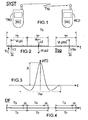
- Fig. 1 depicts a telecommunication system SYST in which the present invention is embodied.
- This system SYST includes at least one transmitter TRD and one receiver RCD, which may for example be both constituted by devices such as mobile phones.
- the number Ns of pulses included in this sequence may, for example, be chosen equal to 128, while the width of each time window may be chosen equal to 100 nanoseconds, with a width of 1 nanosecond for each time chip.
- the transmitter TRD includes symbol encoding means ENC intended to multiply each pulse sequence by an integer value representative of a symbol to be carried by said pulse sequence.
- the information carried by the transmitted signal Tsg will thus essentially be related to the power carried by this signal Tsg, which power is related to the amplitude of the pulses included within said signal Tsg. This information may then be recovered by the receiver RCD without said receiver RCD having to map precisely, with respect to time, the received pulse sequences.
- the receiver RCD includes symbol decoding means DEC intended to compute at least one modulation value representative of an amount of power carried by each pulse sequence and to compare said modulation value to at least one predetermined threshold value.
- symbol decoding means DEC intended to compute at least one modulation value representative of an amount of power carried by each pulse sequence and to compare said modulation value to at least one predetermined threshold value.
- Such frequency interference should be limited as a rule, and is targeted by a European Commission Directive 83/336 CEE, as well as by regulation of the USA's Federal Communications Commission.
- This time-jitter introduced by time-delaying means, will be kept small with respect to a delay spread induced by a communication channel through which the modulated signal will be transmitted.
- the delay spread may have, for example, a value of 100 nanoseconds.
- Such a time-jitter won't affect the information carried by each pulse sequence, and mainly adds an optional degree of flexibility to the modulation scheme according to the invention.
- the information to be carried by the transmitted signal Tsg will be of a binary nature, so that the integer value Vi representative of a bit to be carried by said pulse sequence will either be equal to 1 or to 0.
- Fig.3 is another chronogram which depicts a possible shape p(t) which may be chosen for constituting the above-mentioned pulses.
- p t A . 1 - 4 ⁇ ⁇ ⁇ t / Tw 2 . exp - 2 ⁇ ⁇ ⁇ t / Tw 2 .
- Fig.4 is yet another chronogram which depicts a dataframe DF formed by successive pulse sequences such as the one described above, each having a total duration Ts, a guard interval GI being periodically inserted between two such sequences in order to prevent alteration of a given sequence by a following one, which alterations coud be caused, for example, by intermodulation products between said pulse sequences.
- a device intended to receive such a data frame DF must thus only be able to measure quantities representative of the successive amounts of power carried by the successive pulse sequences in order to identify the informational content of the dataframe DF, without having to map precisely, with respect to time, the received pulse sequences.
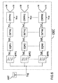
- Fig.5 depicts symbol decoding means DEC included in a receiver according to an embodiment of the invention, in which embodiment the transmitted signal Tsg is a composite signal including a combination of K pulse sequences as described hereinbefore, each pulse sequence having thus been subjected to a symbol encoding step at the transmitting end.
- This receiver includes an antenna device ANT intended to receive such a composite signal Tsg.
- This embodiment enables to transmit simultaneously several symbols through a same communication channel, and thus to significantly increase the throughput of a telecommunication system in which such a variant of the invention is embodied.
- a modulation value Pwk may for example be computed as the integral, on the duration of the channel delay, of the square signal Sqsk delivered by the related squaring module SQMk.
- Each squaring module SQMk may be formed by a Gilbert cell fed with identical input signals.
- Each integrating module INTk may be formed by an operational amplifier provided with an RC feedback.
- Each comparing module CMPMk may be formed by an operational amplifier intended to receive a given modulation value Pwk and the predermined threshold value Thvk assigned to this comparing module CMPMk.
- the symbol decoding means DEC may thus be formed by off-the-shelf analog circuits, which analog circuits are known for their high processing speed and do not require any sampling, as opposed to digital solutions, which will enable to further reduce the processing power and the time required for performing a signal decoding step according to this embodiment of the invention.
- Each predermined threshold value may be predefined and for example set at 1/2 or 3/4 if Vki is to be chosen among integer values 0 and 1.
- the inventors have observed, however, that such fixed thresholds, which do not take into account communication conditions between the transmitter end the receiver may generate decoding errors.
- the inventors thus have designed a thresholding scheme based on an equating of two probability densities, each taking into account real-time communication conditions, so that neither gray zone nor overlap will exist between two interpreting conditions.
- first and second probability densities can be derived from existing art in the field of mathematics applied to optics (A. Bruce Carlson, "Communication Systems An Introduction to Signals and Noise In Electrical Communications, 3 rd Ed.”, McGRAW-HILL, NY).
- E N exp - x + E N
- ⁇ denotes the Euler function and Ij the jth Bessel function of the first kind
- E being an energy carried by the pulse sequence and computed by integrating the transmitted signal over a given time period Ti
- N being a noise intensity adversely affecting the transmission of said signal
- B being a bandwidth of the pulse sequence for which the threshold value is computed.
- the threshold value is defined by a polynom of a variable M 1 ⁇ 2 , which is an approximation of the solution of the above equation system and enables to avoid the computation of an optimal solution to said system.
Landscapes
- Engineering & Computer Science (AREA)
- Computer Networks & Wireless Communication (AREA)
- Signal Processing (AREA)
- Dc Digital Transmission (AREA)
- Digital Transmission Methods That Use Modulated Carrier Waves (AREA)
Abstract
Description
- The present invention relates to a method for transmitting data in a telecommunication system including at least one transmitter and one receiver, said transmitter being intended to transmit a signal formed by at least one sequence of Ns pulses over Ns time windows, each pulse being enclosed within a time chip whose position whithin its relevant time window is defined by a chip number.
- Such data transmission methods are currently studied with the aim of assessing the relevance of so-called Ultra-Wide Band telecommunication systems (further referred to as UWB systems). In such a system each transmitter may be identified by a signature formed by the above-mentioned chip numbers, which signature is in itself quite sturdy and may thus be reliably and accurately communicated to all potential receivers.
- All such data transmission methods, which for example can be the "one-of-many positions modulation" scheme in the
US patent US2002/075972 , the CDMA telecommunication system in which information is to be transmitted by means of pulse frames enclosed in orthogonal superframes (US 5,610,907 ) or the method disclosed by the US patent (US 5,677,927 ) in which information is to be transmitted by means of pulse sequences carried by multiple sub-carriers intended to be modulated in time, involve the receive end to perform a precise mapping with respect of time of a received signal (pulse sequence). - The pulses used in UWB systems are very short, having for example a duration lower than 0,1 nanosecond, which offers to such systems bandwidths at least as large as 10 GigaHertz, entailing high flexibility and hence numerous possible applications for such systems.
- The above-described signal may form a carrying signal on which information can be encoded by modulation of said carrying signal. The inventors have observed that, because of the shortness of the pulses involved, a precise synchronization with a given pulse sequence will be difficult to perform at the receiver end, so that the chosen modulation scheme should involve as few time-related parameters as possible in order to be cost-efficient.
- The present invention thus aims at providing a modulation/demodulation scheme according to which the information carried by pulse sequences may be recovered at the receiver end without said receiver having to map precisely, with respect to time, the received pulse sequences.
- Indeed, a method for transmitting data as described in the opening paragraph is characterized according to the invention in that it includes at least one symbol decoding step to be executed at the receiver end, in the course of which symbol decoding step at least one modulation value representative of an amount of power carried by each pulse sequence is computed and compared to at least one predetermined threshold value, which threshold value will have been computed beforehand by equating a first and a second probability density function representing a likelihood for the transmitted signal to carry a first symbol and a likelihood for the transmitted signal to carry a second symbol, respectively.
- The symbol decoding step according to the invention enables to achieve a demodulation of a modulated UWB symbol in a very straightforward manner, by quantifying the power of the received signal and performing simple comparisons with one or several threshold values, which comparisons are easy to implement. Such a demodulation scheme does not require the receiver to perform a precise mapping, with respect to time, of the received signal, which in turn enables to manufacture adapted receivers at a relatively low cost.
Furthermore, though each predermined threshold value may be predefined and for example set at 1/2 or 3/4 if Vki is to be chosen amonginteger values 0 and 1. The inventors have observed, however, that such fixed thresholds, which do not take into account communication conditions between the transmitter end the receiver may generate decoding errors. The inventors thus have designed a thresholding scheme based on an equation of two probability densities, each taking into account real-time communication conditions, so that neither gray zone nor overlap will exist between two interpreting conditions. - According to a particular embodiment of the invention, the threshold value is defined by a polynom of a variable M½, where M is defined by M=(2.B.Ns.Ti+1)/2, B being a bandwidth of the pulse sequence for which the threshold value is computed, and Ti a time duration over which an integration of each pulse belonging to said pulse sequence is performed in order to compute the amount of power carried by said pulse sequence.
- As will be explained hereinafter, the polynom defining the threshold value will preferably be limited to the second order in order to achieve a suitable balance between computing complexity and decoding efficiency.
- According to a preferred embodiment of the invention, a first-order coefficient of the polynom defining the threshold value is given by an ordinate of a curve whose abcissis is formed by an energy ratio related to the transmission of the relevant pulse sequence.
- The modulation of the UWB signals to be demodulated by carrying out such a symbol decoding step may result from various modulation schemes.
- According to a particular embodiment of the invention, a method as described hereinbefore further includes at least one symbol encoding step to be executed before transmission of said pulse sequence, in the course of which symbol encoding step each pulse sequence is multiplied by an integer value representative of a symbol to be carried by said pulse sequence.
- By virtue of this modulation scheme, the information carried by signals transmitted in Ultra-Wide Band telecommunication systems according to the invention will essentially be related to the power carried by these signals, which power is related to the amplitude of the pulses included within such a signal. Such a modulation scheme is easy to implement, which in turn enables to manufacture adapted transmitters at a relatively low cost.
- According to a variant of the invention, each signal to be transmitted is constituted by a superimposition of a predetermined number of pulse sequences, each pulse sequence having been subjected to a symbol encoding step and corresponding to one of several sub-bands into which a total bandwidth available for transmission has previously been divided.
- This variant of the invention enables to transmit simultaneously several symbols through a same communication channel, and thus to significantly increase the throughput of a telecommunication system in which such a variant of the invention is embodied.
- According to one of its hardware-oriented aspects, the invention also relates to a telecommunication system including at least one transmitter and one receiver, said transmitter being intended to transmit a signal formed by at least one pulse sequence of Ns pulses over Ns time windows, each pulse being enclosed within a time chip whose position whithin its relevant time window is defined by a chip number, system in which the receiver includes symbol decoding means intended to compute at least one modulation value representative of an amount of power carried by each pulse sequence and to compare said modulation value to at least one predetermined threshold value obtained by equating a first and a second probability density function representing the likelihood for the transmitted signal to carry a first symbol and the likelihood for the transmitted signal to carry a second symbol, respectively.
- According to a particular embodiment of this hardware-related aspect, the transmitter includes symbol encoding means intended to multiply each pulse sequence by one of two integer values representative of a symbol to be carried by said pulse sequence.
- According to a variant of this hardware-related aspect, the transmitter further includes signal combination means intended to receive a predetermined number of pulse sequences, each pulse sequence having been generated by symbol encoding means and corresponding to one of several sub-bands into which a total bandwidth available for transmission has previously been divided, said signal combination means being intended to combine all said pulse sequences into a signal to be transmitted.
- According to another of its hardware-oriented aspects, the invention also relates to a device intended to receive a signal formed by at least one sequence of Ns pulses over Ns time windows, each pulse being enclosed within a time chip whose position whithin its relevant time window is defined by a chip number, which receiver includes symbol decoding means intended to compute at least one modulation value representative of an amount of power carried by each pulse sequence and to compare said modulation value to at least one predetermined threshold value obtained by equating a first and a second probability density function representing the likelihood for the transmitted signal to carry a first symbol and the likelihood for the transmitted signal to carry a second symbol, respectively.
- According to yet another of its hardware-oriented aspects, the invention also relates to a device intended to transmit a signal formed by at least one sequence of Ns pulses over Ns time windows, each pulse being enclosed within a time chip whose position whithin its relevant time window is defined by a chip number, which transmitter includes symbol encoding means intended to multiply each pulse sequence by one of two integer values representative of a symbol to be carried by said pulse sequence.
- The characteristics of the invention mentioned above, as well as others, will emerge more clearly from a reading of the following description given in relation to the accompanying figures, amongst which:
-
Fig. 1 is a functional diagram depicting a telecommunication system in which the invention is used; -
Fig.2 is a chronogram depicting a pulse sequence constituting a carrying signal transmitted in such a telecommunication system; -
Fig.3 is a chronogram depicting a pulse model which may be used for generating such a sequence; -
Fig.4 is a chronogram depicting a data frame including a pluralty of pulse sequences; -
Fig.5 is a block diagram depicting symbol decoding means included in a receiver in which a variant of the invention is embodied; -
Fig.6 is a diagram depicting how a threshold value may be dynamically computed according to the invention; and -
Fig.7 is a diagram depicting a tabulated function which may be used for computing such a threshold value according to a preferred embodiment of the invention. -
Fig. 1 depicts a telecommunication system SYST in which the present invention is embodied. This system SYST includes at least one transmitter TRD and one receiver RCD, which may for example be both constituted by devices such as mobile phones. The transmitter TRD is intended to transmit a signal Tsg formed by at least one sequence of Ns pulses pj (for j=1 to Ns) over Ns time windows, each pulse being enclosed within a time chip whose position within its relevant time window is defined by a chip number cj (for j=1 to Ns). The number Ns of pulses included in this sequence may, for example, be chosen equal to 128, while the width of each time window may be chosen equal to 100 nanoseconds, with a width of 1 nanosecond for each time chip. - According to the present invention, the transmitter TRD includes symbol encoding means ENC intended to multiply each pulse sequence by an integer value representative of a symbol to be carried by said pulse sequence.
- The information carried by the transmitted signal Tsg will thus essentially be related to the power carried by this signal Tsg, which power is related to the amplitude of the pulses included within said signal Tsg. This information may then be recovered by the receiver RCD without said receiver RCD having to map precisely, with respect to time, the received pulse sequences.
- To this end, the receiver RCD includes symbol decoding means DEC intended to compute at least one modulation value representative of an amount of power carried by each pulse sequence and to compare said modulation value to at least one predetermined threshold value. As will be explained hereinafter, the result of such a comparison will automatically point to the demodulated value of the symbol originally encoded within the transmitted signal Tsg by the symbol encoding means ENC.
-
Fig.2 depicts such a transmitted signal Tsg in the form of a chronogram, according to which each pulse sequence has a total duration duration Ts divided into Ns time windows having each a duration Tf, each time window being sub-divided into time chips Tc, a single time chip within each window being intended to enclose a pulse pj (for j=1 to Ns), which single time chip is identified by means of a chip number cj. The transmitter of this transmitted signal Tsg will thus be identified by a signature Sg=(c1, c2...cNs) jointly formed by all above-mentioned chip numbers cj (for j=1 to Ns), which signature Sg is in itself quite sturdy and may thus be reliably and accurately communicated to all potential receivers. - In accordance with the invention, each pulse pj (for j=1 to Ns) belonging to the pulse sequence shown in this picture has been multiplied by a same integer value Vi representative of a symbol to be carried by said pulse sequence, in the form of the power carried by this sequence, the reference "i" being indicative of a reference number allocated to the pulse sequence under consideration.
- Furthermore, the pulses pj (for j=1 to Ns) are multiplied by values αj which are randomly chosen equal to +1 or -1 in the course of the symbol encoding step, so that in the example shown here, the second pulse p2 is negative.
- Such a random distribution of positive and negative pulses, which does not affect the information carried by said pulses because said information is related to a square form of said pulses, allows to prevent appearance of high-amplitude peaks in the spectral domain, which peaks could interfere with equipment not included in the telecommunication system. Such frequency interference should be limited as a rule, and is targeted by a European Commission Directive 83/336 CEE, as well as by regulation of the USA's Federal Communications Commission.
- All pulses pj (for j=1 to Ns) of the pulse sequence shown here may additionnally be submitted to a time jitter dti in the course of the symbol encoding step.
- This time-jitter, introduced by time-delaying means, will be kept small with respect to a delay spread induced by a communication channel through which the modulated signal will be transmitted. The delay spread may have, for example, a value of 100 nanoseconds. Such a time-jitter won't affect the information carried by each pulse sequence, and mainly adds an optional degree of flexibility to the modulation scheme according to the invention.
- The transmitted signal Tsg may thus be expressed in the following form :

- In the present application, the information to be carried by the transmitted signal Tsg will be of a binary nature, so that the integer value Vi representative of a bit to be carried by said pulse sequence will either be equal to 1 or to 0.
-
Fig.3 is another chronogram which depicts a possible shape p(t) which may be chosen for constituting the above-mentioned pulses. Pulses pj(t) (for j=1 to Ns) of a same sequence may have different shapes, provided that they all have essentially a same width and carry a same quantity of energy. All pulses pj(t) (for j=1 to Ns) belonging to a same sequence may, however, have a same shape such as the shape p(t) depicted here, which is defined as a derivative of the second order of a Gaussian function, which may be expressed mathematically as:
- Other pulse shapes known to those skilled in the art may, of course, be used in this same purpose.
-
Fig.4 is yet another chronogram which depicts a dataframe DF formed by successive pulse sequences such as the one described above, each having a total duration Ts, a guard interval GI being periodically inserted between two such sequences in order to prevent alteration of a given sequence by a following one, which alterations coud be caused, for example, by intermodulation products between said pulse sequences. This dataframe DF is thus constituted by successive frames having each a duration Tr, whith Tr=Ts+GI, and including each a pulse sequence as described above. - A device intended to receive such a data frame DF must thus only be able to measure quantities representative of the successive amounts of power carried by the successive pulse sequences in order to identify the informational content of the dataframe DF, without having to map precisely, with respect to time, the received pulse sequences.
-
Fig.5 depicts symbol decoding means DEC included in a receiver according to an embodiment of the invention, in which embodiment the transmitted signal Tsg is a composite signal including a combination of K pulse sequences as described hereinbefore, each pulse sequence having thus been subjected to a symbol encoding step at the transmitting end. This receiver includes an antenna device ANT intended to receive such a composite signal Tsg. The decoding means DEC include an array of K band-pass filters PBFk (for k=1 to K) intended to separate from each other K sub-bands into which a total bandwidth used for transmitting the composite signal Tsg has been divided in order to define K different pulse sequences intended each to carry a specific symbol. - This embodiment enables to transmit simultaneously several symbols through a same communication channel, and thus to significantly increase the throughput of a telecommunication system in which such a variant of the invention is embodied.
- In such an embodiment, each pulse sequence corresponding to a given sub-band of rank k (with k=1 to K) will be expressed as :


- In the embodiment of the invention depicted here, the symbol decoding means DEC include an array of K squaring modules SQMk (with k=1 to K), each of which being connected to one of the band-pass filters BPFk and intended to receive a pulse sequence Tsgk (with k=1 to K) and to deliver a signal Sqsk constituted by a square of said signal Tsgk.
- The symbol decoding means DEC further include an array of K integrating modules INTk (with k=1 to K), each of which being connected to one of the squaring modules SQMk and intended to deliver a modulation value Pwk representative of an amount of power carried by the corresponding pulse sequence Tsgk. Such a modulation value Pwk may for example be computed as the integral, on the duration of the channel delay, of the square signal Sqsk delivered by the related squaring module SQMk.
- The symbol decoding means DEC also include an array of K comparing modules CMPMk (with k=1 to K), each of which being connected to one of the integrating modules INTk and intended to compare the modulation value Pwk to be delivered by said integrating module INTk with a predetermined threshold value Thvk, which may be different from one comparing module to another.
- The symbol carried by a given pulse sequence Tsgk will thus be identified in a very straightforward manner, according to a simple decoding grid which may be expressed as follows :
- . If Pwk<Thvk, then the symbol carried by pulse sequence Tsgk is S0;
and - . If Thvk<Pwk, then the symbol carried by pulse sequence Tsgk is S1.
- Each squaring module SQMk may be formed by a Gilbert cell fed with identical input signals. Each integrating module INTk may be formed by an operational amplifier provided with an RC feedback. Each comparing module CMPMk may be formed by an operational amplifier intended to receive a given modulation value Pwk and the predermined threshold value Thvk assigned to this comparing module CMPMk. The symbol decoding means DEC may thus be formed by off-the-shelf analog circuits, which analog circuits are known for their high processing speed and do not require any sampling, as opposed to digital solutions, which will enable to further reduce the processing power and the time required for performing a signal decoding step according to this embodiment of the invention.
- Each predermined threshold value may be predefined and for example set at 1/2 or 3/4 if Vki is to be chosen among
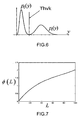
integer values 0 and 1. The inventors have observed, however, that such fixed thresholds, which do not take into account communication conditions between the transmitter end the receiver may generate decoding errors. The inventors thus have designed a thresholding scheme based on an equating of two probability densities, each taking into account real-time communication conditions, so that neither gray zone nor overlap will exist between two interpreting conditions. - Several expressions of first and second probability densities can be derived from existing art in the field of mathematics applied to optics (A. Bruce Carlson, "Communication Systems An Introduction to Signals and Noise In Electrical Communications, 3rd Ed.", McGRAW-HILL, NY). The inventors have, more specifically, singled out probability densities yielded by a so-called "Chi-square" theory, wich gives, when applied by the inventors to the field of UWB transmission, the following expressions for a first probability density p0 representing a likelihood for the transmitted signal to carry a value Vki equal to 0 and a second probability density p1 representing a likelihood for the transmitted signal to carry a value Vki equal to 1 :

-
Fig.6 illustrates the equating p0=p1 of the probability densities defined in the above equation system, to which a threshold value Thvk will provide an optimal solution or, depending on the embodiment chosen for implementing the invention, an approximated solution. - According to a particular embodiment of the invention, the threshold value is defined by a polynom of a variable M½, which is an approximation of the solution of the above equation system and enables to avoid the computation of an optimal solution to said system. This polynom will preferably be limited to the second order in order to achieve a suitable balance between computing complexity and decoding efficiency, and may be expressed as :

- This formula has been singled out by the inventors as providing the best results in terms of computing costs with respect to decoding precision.
- This expression has been derived by the inventors from the above mentioned equation system by using K.x-½.exp(x) as asymptotic equivalent of IM-1(x) for a fixed positive value of K and a large value of x. The term -1 included in the first order variable of the polynom of M½ stems from the mathematical manipulations of the above described equation system and may be dispensed with in other, sub-optimal embodiments of the invention. This expression enables a relatively simple dynamic update of the predetermined threshold value, which will allow to take into account possible variations of communication conditions expressed by variations of the values of M and L.
- According to the preferred embodiment of the invention described above, the first-order coefficient of the polynom defining the threshold value Thvk, i.e. the coefficient in front of the (M-1)½ term, is given by an ordinate of a tabulated curve whose abcissis is formed by an energy ratio L=E/N related to the transmission of the relevant pulse sequence, which curve is shown on
Fig.7 .
Claims (10)
- A method for transmitting data in an UWB telecommunication system including at least one transmitter (TRD) and one receiver (RCD), said transmitter transmitting a signal (Tsg) formed by at least one pulse sequence of Ns pulses over Ns non overlapping windows, each pulse (pj) being enclosed within a time chip whose position within its relevant non overlapping window is defined by a chip number (cj), said method includes at least one symbol decoding step to be executed at the receiver end, characterised in that in the course of said symbol decoding step at least one modulation value (Pwk) representative of an amount of power carried by each pulse sequence is computed and compared to at least one predetermined threshold value (Thvk) in order to recover a symbol carried by said pulse sequence without requiring a precise mapping with respect to time of said pulse sequence, which threshold value will have been computed beforehand by equating a first (P0) and a second (P1) probability density function representing a likelihood for the transmitted signal to carry a first symbol and a likelihood for the transmitted signal to carry a second symbol, respectively.
- A method as claimed in claim 1, characterised in that the threshold value (Thvk) is defined by a polynom of a variable M1/2, where M is defined by M=(2.B.Ns.Ti+1)/2, B being a bandwidth of the pulse sequence for which the threshold value is computed, and Ti a time duration over which an integration of each pulse belonging to said pulse sequence is performed in order to compute the amount of power carried by said pulse sequence.
- A method as claimed in claim 2, characterised in that the polynom defining the threshold value is limited to the second order.
- A method as claimed in any one of claims 2 or 3, characterised in that a first-order coefficient of the polynom defining the threshold value is given by an ordinate of a curve whose abcissas is formed by an energy ratio related to the transmission of the relevant pulse sequence.
- A method as claimed in any one of claims 1 to 4, said method further includes at least one symbol encoding step to be executed before transmission of said pulse sequence, characterised in that in the course of saidsymbol encoding step each pulse sequence is multiplied by one of two integer values representative of a symbol to be carried by said pulse sequence.
- A method as claimed in any one of claims 1 to 5, characterised in that each signal to be transmitted is constituted by a superimposition of a predetermined number of pulse sequences, each pulse sequence having been subjected to a symbol encoding step and corresponding to one of several sub-bands into which a total bandwidth available for transmission has previously been divided.
- A receiver (RCD) adapted to receive a signal (Tsg) transmitted by a transmitter (TRD), said signal being formed by at least one sequence of Ns pulses over Ns non overlapping windows, each pulse (pj) being enclosed within a time chip whose position within its relevant time window is defined by a chip number (cj), characterised in that said receiver (RCD) includes symbol decoding means (DEC) computing at least one modulation value (Pwk) representative of an amount of power carried by each pulse sequence and to compare said modulation value to at least one predetermined threshold value (Thvk) in order to recover a symbol carried by said pulse sequence without requiring a precise mapping with respect to time of said pulse sequence, which threshold value is obtained by equating a first (P0) and a second (P1) probability density function representing the likelihood for the transmitted signal to carry a first symbol and the likelihood for the transmitted signal to carry a second symbol, respectively.
- An UWB telecommunication system including at least one transmitter (TRD) and one receiver (RCD) according to claim 7, said transmitter being adapted to transmit a signal (Tsg) formed by at least one pulse sequence of Ns pulses over Ns non overlapping windows, each pulse (pj) being enclosed within a time chip whose position within its relevant non overlapping window is defined by a chip number (cj).
- An UWB telecommunication system as claimed in claim 8, characterised in that said transmitter includes symbol encoding means (ENC) intended to multiply each pulse sequence by one of two integer values representative of a symbol to be carried by said pulse sequence.
- An UWB telecommunication system as claimed in any one of claims 8 or 9, characterised in that the transmitter further includes signal combination means intended to receive a predetermined number of pulse sequences, each pulse sequence having been generated by symbol encoding means and corresponding to one of several sub-bands into which a total bandwidth available for transmission has previously been divided, said signal combination means being intended to combine all said pulse sequences into a signal to be transmitted.
Priority Applications (6)
| Application Number | Priority Date | Filing Date | Title |
|---|---|---|---|
| EP03293200A EP1545018B1 (en) | 2003-12-17 | 2003-12-17 | Method for demodulating UWB pulse sequences encoded according to an On-Off Keying modulation scheme |
| DE60324440T DE60324440D1 (en) | 2003-12-17 | 2003-12-17 | Demodulation method of encoded with an on-off keying modulation method ultra broadband pulse sequences |
| AT03293200T ATE413020T1 (en) | 2003-12-17 | 2003-12-17 | DEMODULATION METHOD OF ULTRA WIDEBAND PULSE SEQUENCES CODED USING AN ON-OFF KEYING MODULATION METHOD |
| US10/998,930 US7817728B2 (en) | 2003-12-17 | 2004-11-30 | Method for demodulating UWB pulse sequences encoded according to an on-off keying modulation scheme |
| CN2004100954035A CN1630211B (en) | 2003-12-17 | 2004-12-16 | Method for demodulating UWB pulse sequences encoded according to an on-off keying modulation scheme |
| JP2004366564A JP2005218079A (en) | 2003-12-17 | 2004-12-17 | METHOD FOR TRANSMITTING DATA IN COMMUNICATION SYSTEM INCLUDING AT LEAST ONE TRANSMITTER AND ONE RECEIVER, COMMUNICATION SYSTEM INCLUDING AT LEAST ONE TRANSMITTER AND ONE RECEIVER, AND DEVICE CONFIGURED SO AS TO TRANSMIT AND RECEIVE SIGNAL FORMED BY AT LEAST ONE SEQUENCE COMPOSED OF Ns PULSES OVER Ns TIME WINDOWS |
Applications Claiming Priority (1)
| Application Number | Priority Date | Filing Date | Title |
|---|---|---|---|
| EP03293200A EP1545018B1 (en) | 2003-12-17 | 2003-12-17 | Method for demodulating UWB pulse sequences encoded according to an On-Off Keying modulation scheme |
Publications (2)
| Publication Number | Publication Date |
|---|---|
| EP1545018A1 EP1545018A1 (en) | 2005-06-22 |
| EP1545018B1 true EP1545018B1 (en) | 2008-10-29 |
Family
ID=34486485
Family Applications (1)
| Application Number | Title | Priority Date | Filing Date |
|---|---|---|---|
| EP03293200A Expired - Lifetime EP1545018B1 (en) | 2003-12-17 | 2003-12-17 | Method for demodulating UWB pulse sequences encoded according to an On-Off Keying modulation scheme |
Country Status (6)
| Country | Link |
|---|---|
| US (1) | US7817728B2 (en) |
| EP (1) | EP1545018B1 (en) |
| JP (1) | JP2005218079A (en) |
| CN (1) | CN1630211B (en) |
| AT (1) | ATE413020T1 (en) |
| DE (1) | DE60324440D1 (en) |
Cited By (1)
| Publication number | Priority date | Publication date | Assignee | Title |
|---|---|---|---|---|
| JP2005218079A (en) * | 2003-12-17 | 2005-08-11 | Mitsubishi Electric Information Technology Centre Europa Bv | METHOD FOR TRANSMITTING DATA IN COMMUNICATION SYSTEM INCLUDING AT LEAST ONE TRANSMITTER AND ONE RECEIVER, COMMUNICATION SYSTEM INCLUDING AT LEAST ONE TRANSMITTER AND ONE RECEIVER, AND DEVICE CONFIGURED SO AS TO TRANSMIT AND RECEIVE SIGNAL FORMED BY AT LEAST ONE SEQUENCE COMPOSED OF Ns PULSES OVER Ns TIME WINDOWS |
Families Citing this family (7)
| Publication number | Priority date | Publication date | Assignee | Title |
|---|---|---|---|---|
| EP1523106B1 (en) * | 2003-10-09 | 2007-08-08 | Mitsubishi Electric Information Technology Centre Europe B.V. | Method for demodulating UWB pulse sequences |
| DE60321915D1 (en) * | 2003-10-09 | 2008-08-14 | Mitsubishi Electric Corp | Method for modulating ultra-wideband pulse sequences |
| KR100690089B1 (en) | 2005-12-16 | 2007-03-08 | 한국전기연구원 | Optimum threshold calculation method using the characteristics of chi-square probability density functions for noncoherent uwb systems |
| CN100362752C (en) * | 2006-03-21 | 2008-01-16 | 东南大学 | Method and device for realizing radio-frequency front end with low complexity and super-wide band |
| CN102761902B (en) | 2011-04-29 | 2014-07-09 | 华为技术有限公司 | Method for activating capacity station, wireless communication device and system |
| CN103503320B (en) | 2011-05-23 | 2016-10-05 | 华为技术有限公司 | For reconstructing method and the decoder of source signal |
| CN113644850B (en) * | 2021-07-12 | 2023-12-22 | 南京国电南自维美德自动化有限公司 | Pulse hybrid transmission method and system of excitation system |
Family Cites Families (23)
| Publication number | Priority date | Publication date | Assignee | Title |
|---|---|---|---|---|
| US5610907A (en) * | 1994-07-29 | 1997-03-11 | Barrett; Terence W. | Ultrafast time hopping CDMA-RF communications: code-as-carrier, multichannel operation, high data rate operation and data rate on demand |
| US5677927A (en) * | 1994-09-20 | 1997-10-14 | Pulson Communications Corporation | Ultrawide-band communication system and method |
| CN1249098A (en) * | 1997-03-07 | 2000-03-29 | 贝瑞特控股公司 | Improvement in ultrafast time hopping CDMA-RF |
| JP2000174830A (en) * | 1998-12-09 | 2000-06-23 | Nec Corp | Method and device for demodulating ask |
| US6810087B2 (en) * | 2000-01-04 | 2004-10-26 | General Electric Company | Ultra-wideband communications system |
| US6556621B1 (en) * | 2000-03-29 | 2003-04-29 | Time Domain Corporation | System for fast lock and acquisition of ultra-wideband signals |
| US6937667B1 (en) * | 2000-03-29 | 2005-08-30 | Time Domain Corporation | Apparatus, system and method for flip modulation in an impulse radio communications system |
| US20020075972A1 (en) * | 2000-03-29 | 2002-06-20 | Time Domain Corporation | Apparatus, system and method for one-of-many positions modulation in an impulse radio communications system |
| US7145954B1 (en) * | 2000-06-12 | 2006-12-05 | Time Domain Corporation | Method and apparatus for mapping pulses to a non-fixed layout |
| AU2001270063A1 (en) * | 2000-06-21 | 2002-01-02 | Pulse-Link, Inc. | Ultra wide band base band receiver |
| JP2002325071A (en) * | 2001-04-25 | 2002-11-08 | Sony Corp | Transmitter, receiver, transmitting method and receiving method |
| JP2003061057A (en) * | 2001-08-14 | 2003-02-28 | Sony Corp | Device, method and program for data detection |
| JP2003152594A (en) * | 2001-11-19 | 2003-05-23 | Sony Corp | Apparatus and method for transmitting, apparatus and method for receiving, system and method for communicating, and program |
| JP2003174368A (en) * | 2001-12-06 | 2003-06-20 | Sony Corp | Radio communication equipment, method for controlling transmission output, storage medium, and computer program |
| JP2003218963A (en) * | 2001-12-07 | 2003-07-31 | Applied Microcircuits Corp | Feed-forward/feedback system and method for non-casual channel equalization |
| JP2005518720A (en) * | 2002-02-20 | 2005-06-23 | エクストリームスペクトラム,インコーポレイテッド | M-ary orthogonal coded communication method and system |
| AU2003222230A1 (en) * | 2002-02-20 | 2003-09-09 | General Atomics | Method and apparatus for adapting multi-band ultra-wideband signaling to interference sources |
| JP2004208110A (en) * | 2002-12-26 | 2004-07-22 | Casio Comput Co Ltd | Radio communication system, receiver and information receiving method |
| US7764725B2 (en) * | 2003-02-14 | 2010-07-27 | Koninklijke Philips Electronics N.V. | Sub-banded ultra-wideband communication system |
| US20040179631A1 (en) * | 2003-03-13 | 2004-09-16 | Telecommunications Research Laboratories | UWB receiver architecture |
| EP1526648A1 (en) * | 2003-10-21 | 2005-04-27 | Mitsubishi Electric Information Technology Centre Europe B.V. | System and device for modulating UWB pulse sequences |
| US7295638B2 (en) * | 2003-11-17 | 2007-11-13 | Motorola, Inc. | Communication device |
| EP1545018B1 (en) * | 2003-12-17 | 2008-10-29 | Mitsubishi Electric Information Technology Centre Europe B.V. | Method for demodulating UWB pulse sequences encoded according to an On-Off Keying modulation scheme |
-
2003
- 2003-12-17 EP EP03293200A patent/EP1545018B1/en not_active Expired - Lifetime
- 2003-12-17 AT AT03293200T patent/ATE413020T1/en not_active IP Right Cessation
- 2003-12-17 DE DE60324440T patent/DE60324440D1/en not_active Expired - Lifetime
-
2004
- 2004-11-30 US US10/998,930 patent/US7817728B2/en not_active Expired - Fee Related
- 2004-12-16 CN CN2004100954035A patent/CN1630211B/en not_active Expired - Fee Related
- 2004-12-17 JP JP2004366564A patent/JP2005218079A/en active Pending
Cited By (1)
| Publication number | Priority date | Publication date | Assignee | Title |
|---|---|---|---|---|
| JP2005218079A (en) * | 2003-12-17 | 2005-08-11 | Mitsubishi Electric Information Technology Centre Europa Bv | METHOD FOR TRANSMITTING DATA IN COMMUNICATION SYSTEM INCLUDING AT LEAST ONE TRANSMITTER AND ONE RECEIVER, COMMUNICATION SYSTEM INCLUDING AT LEAST ONE TRANSMITTER AND ONE RECEIVER, AND DEVICE CONFIGURED SO AS TO TRANSMIT AND RECEIVE SIGNAL FORMED BY AT LEAST ONE SEQUENCE COMPOSED OF Ns PULSES OVER Ns TIME WINDOWS |
Also Published As
| Publication number | Publication date |
|---|---|
| EP1545018A1 (en) | 2005-06-22 |
| JP2005218079A (en) | 2005-08-11 |
| CN1630211B (en) | 2010-05-26 |
| US7817728B2 (en) | 2010-10-19 |
| CN1630211A (en) | 2005-06-22 |
| DE60324440D1 (en) | 2008-12-11 |
| ATE413020T1 (en) | 2008-11-15 |
| US20050213673A1 (en) | 2005-09-29 |
Similar Documents
| Publication | Publication Date | Title |
|---|---|---|
| US20040057501A1 (en) | Systems and methods for providing adaptive pulse position modulated code division multiple access for ultra-wideband communication links | |
| Ramirez-Mireles et al. | Multiple-access performance limits with time hopping and pulse position modulation | |
| US20040242155A1 (en) | UWB communication receiver feedback loop | |
| US20090296831A1 (en) | Wireless Communication Method and System | |
| EP1545018B1 (en) | Method for demodulating UWB pulse sequences encoded according to an On-Off Keying modulation scheme | |
| EP1701453B1 (en) | Method for detecting UWB pulse sequences in a cost-efficient manner | |
| EP1701454B1 (en) | Method for transmitting UWB pulse sequences in a cost-efficient manner | |
| EP1568148B1 (en) | Selective data inversion in ultra-wide-band communications to eliminate line frequencies | |
| US7539234B2 (en) | System and device for modulating UWB pulse sequences | |
| EP1523106B1 (en) | Method for demodulating UWB pulse sequences | |
| US7613255B2 (en) | Method for estimating communication conditions affecting an UWB wireless link | |
| US7075382B2 (en) | Method and apparatus for modulating a pulse signal with a bit stream | |
| Gomes et al. | Performance evaluation of UWB wireless link | |
| US7792210B2 (en) | Method for modulating UWB pulse sequences | |
| JP2006525760A (en) | Method and apparatus for reducing individual power spectral density components in a multiband broadband communication system | |
| EP1622281B1 (en) | Multiple Band UWB telecommunication system using multiple antennas. | |
| Khalesehosseini et al. | Generalized CRLB for DA and NDA synchronization of UWB signals with clock offset | |
| Beaulieu et al. | On the PDF of multiple access interference in time-hopping UWB systems | |
| Zhang et al. | Performance analysis of non-orthogonal pulse position modulation for time-hopping UWB transmission |
Legal Events
| Date | Code | Title | Description |
|---|---|---|---|
| PUAI | Public reference made under article 153(3) epc to a published international application that has entered the european phase |
Free format text: ORIGINAL CODE: 0009012 |
|
| AK | Designated contracting states |
Kind code of ref document: A1 Designated state(s): AT BE BG CH CY CZ DE DK EE ES FI FR GB GR HU IE IT LI LU MC NL PT RO SE SI SK TR |
|
| AX | Request for extension of the european patent |
Extension state: AL LT LV MK |
|
| 17P | Request for examination filed |
Effective date: 20050823 |
|
| AKX | Designation fees paid |
Designated state(s): AT BE BG CH CY CZ DE DK EE ES FI FR GB GR HU IE IT LI LU MC NL PT RO SE SI SK TR |
|
| RAP1 | Party data changed (applicant data changed or rights of an application transferred) |
Owner name: MITSUBISHI DENKI KABUSHIKI KAISHA Owner name: MITSUBISHI ELECTRIC INFORMATION TECHNOLOGY CENTRE |
|
| 17Q | First examination report despatched |
Effective date: 20050930 |
|
| GRAP | Despatch of communication of intention to grant a patent |
Free format text: ORIGINAL CODE: EPIDOSNIGR1 |
|
| RIN1 | Information on inventor provided before grant (corrected) |
Inventor name: PAQUELET, STEPHANE,MITSUBISHI ELECTRICITE Inventor name: AUBERT, LOUIS-MARIE,MITSUBISHI ELECTRICITE Inventor name: MEUNIER, CLAIRE,U |
|
| GRAS | Grant fee paid |
Free format text: ORIGINAL CODE: EPIDOSNIGR3 |
|
| GRAA | (expected) grant |
Free format text: ORIGINAL CODE: 0009210 |
|
| AK | Designated contracting states |
Kind code of ref document: B1 Designated state(s): AT BE BG CH CY CZ DE DK EE ES FI FR GB GR HU IE IT LI LU MC NL PT RO SE SI SK TR |
|
| REG | Reference to a national code |
Ref country code: GB Ref legal event code: FG4D |
|
| REG | Reference to a national code |
Ref country code: CH Ref legal event code: EP |
|
| REG | Reference to a national code |
Ref country code: IE Ref legal event code: FG4D |
|
| REF | Corresponds to: |
Ref document number: 60324440 Country of ref document: DE Date of ref document: 20081211 Kind code of ref document: P |
|
| NLV1 | Nl: lapsed or annulled due to failure to fulfill the requirements of art. 29p and 29m of the patents act | ||
| PG25 | Lapsed in a contracting state [announced via postgrant information from national office to epo] |
Ref country code: AT Free format text: LAPSE BECAUSE OF FAILURE TO SUBMIT A TRANSLATION OF THE DESCRIPTION OR TO PAY THE FEE WITHIN THE PRESCRIBED TIME-LIMIT Effective date: 20081029 Ref country code: ES Free format text: LAPSE BECAUSE OF FAILURE TO SUBMIT A TRANSLATION OF THE DESCRIPTION OR TO PAY THE FEE WITHIN THE PRESCRIBED TIME-LIMIT Effective date: 20090209 Ref country code: BG Free format text: LAPSE BECAUSE OF FAILURE TO SUBMIT A TRANSLATION OF THE DESCRIPTION OR TO PAY THE FEE WITHIN THE PRESCRIBED TIME-LIMIT Effective date: 20090129 |
|
| PG25 | Lapsed in a contracting state [announced via postgrant information from national office to epo] |
Ref country code: FI Free format text: LAPSE BECAUSE OF FAILURE TO SUBMIT A TRANSLATION OF THE DESCRIPTION OR TO PAY THE FEE WITHIN THE PRESCRIBED TIME-LIMIT Effective date: 20081029 Ref country code: PT Free format text: LAPSE BECAUSE OF FAILURE TO SUBMIT A TRANSLATION OF THE DESCRIPTION OR TO PAY THE FEE WITHIN THE PRESCRIBED TIME-LIMIT Effective date: 20090330 Ref country code: SI Free format text: LAPSE BECAUSE OF FAILURE TO SUBMIT A TRANSLATION OF THE DESCRIPTION OR TO PAY THE FEE WITHIN THE PRESCRIBED TIME-LIMIT Effective date: 20081029 Ref country code: NL Free format text: LAPSE BECAUSE OF FAILURE TO SUBMIT A TRANSLATION OF THE DESCRIPTION OR TO PAY THE FEE WITHIN THE PRESCRIBED TIME-LIMIT Effective date: 20081029 |
|
| PG25 | Lapsed in a contracting state [announced via postgrant information from national office to epo] |
Ref country code: DK Free format text: LAPSE BECAUSE OF FAILURE TO SUBMIT A TRANSLATION OF THE DESCRIPTION OR TO PAY THE FEE WITHIN THE PRESCRIBED TIME-LIMIT Effective date: 20081029 Ref country code: BE Free format text: LAPSE BECAUSE OF FAILURE TO SUBMIT A TRANSLATION OF THE DESCRIPTION OR TO PAY THE FEE WITHIN THE PRESCRIBED TIME-LIMIT Effective date: 20081029 Ref country code: RO Free format text: LAPSE BECAUSE OF FAILURE TO SUBMIT A TRANSLATION OF THE DESCRIPTION OR TO PAY THE FEE WITHIN THE PRESCRIBED TIME-LIMIT Effective date: 20081029 Ref country code: EE Free format text: LAPSE BECAUSE OF FAILURE TO SUBMIT A TRANSLATION OF THE DESCRIPTION OR TO PAY THE FEE WITHIN THE PRESCRIBED TIME-LIMIT Effective date: 20081029 Ref country code: MC Free format text: LAPSE BECAUSE OF NON-PAYMENT OF DUE FEES Effective date: 20081231 |
|
| REG | Reference to a national code |
Ref country code: CH Ref legal event code: PL |
|
| PG25 | Lapsed in a contracting state [announced via postgrant information from national office to epo] |
Ref country code: IT Free format text: LAPSE BECAUSE OF FAILURE TO SUBMIT A TRANSLATION OF THE DESCRIPTION OR TO PAY THE FEE WITHIN THE PRESCRIBED TIME-LIMIT Effective date: 20081029 Ref country code: CZ Free format text: LAPSE BECAUSE OF FAILURE TO SUBMIT A TRANSLATION OF THE DESCRIPTION OR TO PAY THE FEE WITHIN THE PRESCRIBED TIME-LIMIT Effective date: 20081029 Ref country code: SE Free format text: LAPSE BECAUSE OF FAILURE TO SUBMIT A TRANSLATION OF THE DESCRIPTION OR TO PAY THE FEE WITHIN THE PRESCRIBED TIME-LIMIT Effective date: 20090129 |
|
| PLBE | No opposition filed within time limit |
Free format text: ORIGINAL CODE: 0009261 |
|
| STAA | Information on the status of an ep patent application or granted ep patent |
Free format text: STATUS: NO OPPOSITION FILED WITHIN TIME LIMIT |
|
| PG25 | Lapsed in a contracting state [announced via postgrant information from national office to epo] |
Ref country code: SK Free format text: LAPSE BECAUSE OF FAILURE TO SUBMIT A TRANSLATION OF THE DESCRIPTION OR TO PAY THE FEE WITHIN THE PRESCRIBED TIME-LIMIT Effective date: 20081029 |
|
| 26N | No opposition filed |
Effective date: 20090730 |
|
| PG25 | Lapsed in a contracting state [announced via postgrant information from national office to epo] |
Ref country code: CH Free format text: LAPSE BECAUSE OF NON-PAYMENT OF DUE FEES Effective date: 20081231 Ref country code: IE Free format text: LAPSE BECAUSE OF NON-PAYMENT OF DUE FEES Effective date: 20081217 Ref country code: LI Free format text: LAPSE BECAUSE OF NON-PAYMENT OF DUE FEES Effective date: 20081231 |
|
| PG25 | Lapsed in a contracting state [announced via postgrant information from national office to epo] |
Ref country code: CY Free format text: LAPSE BECAUSE OF FAILURE TO SUBMIT A TRANSLATION OF THE DESCRIPTION OR TO PAY THE FEE WITHIN THE PRESCRIBED TIME-LIMIT Effective date: 20081029 Ref country code: LU Free format text: LAPSE BECAUSE OF NON-PAYMENT OF DUE FEES Effective date: 20081217 Ref country code: HU Free format text: LAPSE BECAUSE OF FAILURE TO SUBMIT A TRANSLATION OF THE DESCRIPTION OR TO PAY THE FEE WITHIN THE PRESCRIBED TIME-LIMIT Effective date: 20090430 |
|
| PG25 | Lapsed in a contracting state [announced via postgrant information from national office to epo] |
Ref country code: TR Free format text: LAPSE BECAUSE OF FAILURE TO SUBMIT A TRANSLATION OF THE DESCRIPTION OR TO PAY THE FEE WITHIN THE PRESCRIBED TIME-LIMIT Effective date: 20081029 |
|
| PG25 | Lapsed in a contracting state [announced via postgrant information from national office to epo] |
Ref country code: GR Free format text: LAPSE BECAUSE OF FAILURE TO SUBMIT A TRANSLATION OF THE DESCRIPTION OR TO PAY THE FEE WITHIN THE PRESCRIBED TIME-LIMIT Effective date: 20090130 |
|
| PGFP | Annual fee paid to national office [announced via postgrant information from national office to epo] |
Ref country code: GB Payment date: 20101112 Year of fee payment: 8 |
|
| PGFP | Annual fee paid to national office [announced via postgrant information from national office to epo] |
Ref country code: FR Payment date: 20120110 Year of fee payment: 9 |
|
| PGFP | Annual fee paid to national office [announced via postgrant information from national office to epo] |
Ref country code: DE Payment date: 20111216 Year of fee payment: 9 |
|
| GBPC | Gb: european patent ceased through non-payment of renewal fee |
Effective date: 20121217 |
|
| REG | Reference to a national code |
Ref country code: FR Ref legal event code: ST Effective date: 20130830 |
|
| REG | Reference to a national code |
Ref country code: DE Ref legal event code: R119 Ref document number: 60324440 Country of ref document: DE Effective date: 20130702 |
|
| PG25 | Lapsed in a contracting state [announced via postgrant information from national office to epo] |
Ref country code: DE Free format text: LAPSE BECAUSE OF NON-PAYMENT OF DUE FEES Effective date: 20130702 |
|
| PG25 | Lapsed in a contracting state [announced via postgrant information from national office to epo] |
Ref country code: FR Free format text: LAPSE BECAUSE OF NON-PAYMENT OF DUE FEES Effective date: 20130102 Ref country code: GB Free format text: LAPSE BECAUSE OF NON-PAYMENT OF DUE FEES Effective date: 20121217 |